JP4290042B2 - Login management program, medium storing login management program, login management apparatus, and login management method - Google Patents
Login management program, medium storing login management program, login management apparatus, and login management method Download PDFInfo
- Publication number
- JP4290042B2 JP4290042B2 JP2004072016A JP2004072016A JP4290042B2 JP 4290042 B2 JP4290042 B2 JP 4290042B2 JP 2004072016 A JP2004072016 A JP 2004072016A JP 2004072016 A JP2004072016 A JP 2004072016A JP 4290042 B2 JP4290042 B2 JP 4290042B2
- Authority
- JP
- Japan
- Prior art keywords
- user
- time
- data
- login
- storage device
- Prior art date
- Legal status (The legal status is an assumption and is not a legal conclusion. Google has not performed a legal analysis and makes no representation as to the accuracy of the status listed.)
- Expired - Lifetime
Links
- 238000007726 management method Methods 0.000 title claims description 66
- 238000000034 method Methods 0.000 claims description 75
- 238000013500 data storage Methods 0.000 claims description 52
- 238000003860 storage Methods 0.000 claims description 49
- 230000004044 response Effects 0.000 claims description 10
- 238000012545 processing Methods 0.000 description 89
- 230000008569 process Effects 0.000 description 69
- 238000012937 correction Methods 0.000 description 17
- 238000004519 manufacturing process Methods 0.000 description 6
- 239000000284 extract Substances 0.000 description 5
- 230000007704 transition Effects 0.000 description 5
- 238000005516 engineering process Methods 0.000 description 4
- 238000004891 communication Methods 0.000 description 3
- 230000002776 aggregation Effects 0.000 description 2
- 238000004220 aggregation Methods 0.000 description 2
- 238000010586 diagram Methods 0.000 description 2
- 238000005259 measurement Methods 0.000 description 2
- 238000007796 conventional method Methods 0.000 description 1
- 235000014510 cooky Nutrition 0.000 description 1
- 238000001514 detection method Methods 0.000 description 1
- 230000000694 effects Effects 0.000 description 1
- 230000006870 function Effects 0.000 description 1
- 230000010365 information processing Effects 0.000 description 1
- 238000009434 installation Methods 0.000 description 1
- 239000004065 semiconductor Substances 0.000 description 1
- 239000000725 suspension Substances 0.000 description 1
Images


Classifications
-
- G—PHYSICS
- G06—COMPUTING; CALCULATING OR COUNTING
- G06F—ELECTRIC DIGITAL DATA PROCESSING
- G06F21/00—Security arrangements for protecting computers, components thereof, programs or data against unauthorised activity
- G06F21/10—Protecting distributed programs or content, e.g. vending or licensing of copyrighted material ; Digital rights management [DRM]
- G06F21/105—Arrangements for software license management or administration, e.g. for managing licenses at corporate level
-
- G—PHYSICS
- G06—COMPUTING; CALCULATING OR COUNTING
- G06F—ELECTRIC DIGITAL DATA PROCESSING
- G06F21/00—Security arrangements for protecting computers, components thereof, programs or data against unauthorised activity
- G06F21/30—Authentication, i.e. establishing the identity or authorisation of security principals
- G06F21/31—User authentication
-
- G—PHYSICS
- G06—COMPUTING; CALCULATING OR COUNTING
- G06F—ELECTRIC DIGITAL DATA PROCESSING
- G06F2221/00—Indexing scheme relating to security arrangements for protecting computers, components thereof, programs or data against unauthorised activity
- G06F2221/21—Indexing scheme relating to G06F21/00 and subgroups addressing additional information or applications relating to security arrangements for protecting computers, components thereof, programs or data against unauthorised activity
- G06F2221/2137—Time limited access, e.g. to a computer or data
Description
本発明は、ユーザ・ライセンスを有効利用するための情報処理技術に関するものである。 The present invention relates to an information processing technique for effectively using a user license.
近年、ERP(Enterprise Resource Planning)パッケージを導入する企業が増えている。ERPパッケージの導入にあたっては、ユーザの同時接続数に応じた料金体系に従った契約がなされることが多くなっている。このような場合、実際の運用において、契約数分の接続がなされている状態では、新たなログイン要求は拒否される。すなわち、新たにログインしたいユーザは、ログインしているユーザのうちいずれかのユーザがログオフしない限り、ログインすることができない。一方で、ログインしているユーザは、ログインからログオフまでの間に、必ずしもERPパッケージを用いた業務を継続して行っているとは限らない。例えば、ログインしたまま別の作業を行っているような場合も多い。 In recent years, an increasing number of companies have introduced ERP (Enterprise Resource Planning) packages. In introducing ERP packages, contracts are often made in accordance with a fee structure corresponding to the number of simultaneous connections of users. In such a case, a new login request is rejected in the actual operation in a state where connections for the number of contracts are made. In other words, a user who wants to newly log in cannot log in unless one of the logged-in users logs off. On the other hand, the logged-in user does not always continue to perform the business using the ERP package from login to log-off. For example, there are many cases where other work is performed while logged in.
このように、ログイン状態を保つ必要がないユーザであっても、ログオフしない限りは同時接続数にカウントされているため、ログインしてERPパッケージを用いた業務を行いたいユーザがログインできない場合が生ずる。従って、ERPパッケージを用いた業務を実際に行う場合のみログイン状態を保持できるようにすれば、同時にログインしているユーザ数を少なくすることができ、契約する同時接続数を減らすことも可能となる。 In this way, even a user who does not need to maintain a login state is counted as the number of simultaneous connections unless logging off, and thus a user who wants to log in and perform business using the ERP package may not be able to log in. . Therefore, if the login state can be maintained only when the business using the ERP package is actually performed, the number of users who are logged in at the same time can be reduced, and the number of simultaneous connections to be contracted can be reduced. .
例えば、ログイン時間を制限するための技術が存在する(例えば特許文献1参照)。すなわち、各コンピュータ端末は、ホストコンピュータとの接続がなされた後にユーザからデータベース検索のためのコマンドが継続して入力されない無入力時間が、基準時間に達したか否かを監視する。基準時間は各コンピュータ端末の画面上に表示させた基準時間設定画面で設定できる。各コンピュータ端末は、無入力時間が基準時間に達すると、その旨をユーザに知らせるための警告画面を画面上に表示する。その警告画面が表示された後一定時間内にユーザからコマンドが入力されないと、当該コンピュータ端末との接続を強制的に切断させるための強制ログオフ・コマンドをホストコンピュータに送る。
しかしながら、このような従来技術では、ユーザの同時接続数が限られている環境において、効率良くユーザ・ライセンスを利用しているとは必ずしも言えない。なぜなら、ユーザの判断によって強制的なログオフまでの時間を設定できることから、ユーザによっては、強制的なログオフまでの時間を実際に必要な時間よりも長めに設定することが考えられるためである。すなわち、従来技術によると、ユーザがログオフするのを忘れても自動的にログオフがなされるということから、ログオフを忘れることへの対策としては効果を期待することができるが、他のユーザの利用可能時間を増やすという点については十分考慮されているとは言えない。 However, such a conventional technique cannot always be said to efficiently use a user license in an environment where the number of simultaneous connections of users is limited. This is because the time until the forced logoff can be set according to the user's judgment, and it is considered that the time until the forced logoff may be set longer than the actually required time depending on the user. In other words, according to the conventional technology, even if the user forgets to log off, the log off is automatically performed, so it can be expected to be effective as a countermeasure against forgetting to log off, but the use of other users The point of increasing the possible time is not considered enough.
そのため、本発明の目的は、ユーザの同時接続数が限られている環境において、ユーザ・ライセンスの利用効率を向上させるための技術を提供することである。 Therefore, an object of the present invention is to provide a technique for improving the usage efficiency of a user license in an environment where the number of simultaneous connections of users is limited.
本発明に係るログイン管理方法は、ユーザによるログインが必要であり且つ複数種類の業務を取り扱うコンピュータ・システムにより実行されるログイン管理方法であって、ユーザにより選択された業務とユーザの属性とに基づき、所定の許容時間を決定し、記憶装置に格納するステップと、記憶装置に格納された所定の許容時間を超えて、選択された業務に係るデータが未入力又は未受信であることを検出した場合、ユーザを強制的にログオフさせるログオフ・ステップとを含む。 The login management method according to the present invention is a login management method that is executed by a computer system that requires login by a user and handles a plurality of types of business, and is based on the business selected by the user and the attributes of the user. Determining a predetermined permissible time and storing it in the storage device, and detecting that the data relating to the selected job has not been entered or received beyond the predetermined permissible time stored in the storage device A logoff step forcing the user to log off.
これにより、例えばユーザが取り扱う業務及びユーザが属する部門に応じて、強制的にログオフされるまでの時間が自動で設定される。とりわけERPパッケージは、処理に必要なログイン時間が異なる様々な業務や、作業スタイルが異なる様々な部門に属するユーザによる業務に対応している。従って、本発明によれば、強制的にログオフされるまでの時間を適切に設定することができる。また、このように設定された時間に基づき、処理を行っていないと判断されるユーザを強制的にログオフさせることにより、接続可能なユーザ数が増え、ユーザ・ライセンスの利用効率さらには業務効率を向上させることができる。 Thereby, for example, the time until forcibly logging off is automatically set according to the business handled by the user and the department to which the user belongs. In particular, the ERP package supports various tasks with different login times required for processing and tasks by users belonging to various departments with different work styles. Therefore, according to the present invention, it is possible to appropriately set the time until forcibly logging off. Also, by forcibly logging off users who are determined not to perform processing based on the time set in this way, the number of connectable users increases, and user license usage efficiency and business efficiency are improved. Can be improved.
また、上記ログオフ・ステップが、ユーザが操作する端末に表示させている画面に関するデータを、ユーザに対応付けて画面データ記憶部に格納するステップを含み、本発明に係るログイン管理方法が、強制的にログオフされたユーザによる再ログインに応じて、画面データ記憶部に格納された画面に関するデータを用いて、ユーザが操作する端末に画面を表示させるステップをさらに含むようにしてもよい。 The logoff step includes a step of storing data relating to a screen displayed on a terminal operated by a user in a screen data storage unit in association with the user, and the login management method according to the present invention is compulsory. In response to re-login by the user who has been logged off, a step of displaying a screen on a terminal operated by the user may be further included using data relating to the screen stored in the screen data storage unit.
これにより、強制的にログオフされたユーザは、ログオフされたからといって1から処理をやり直す必要がなくなる。通常、ERPパッケージでは、メインメニューから業務を選択し、画面遷移を行いながら処理を進めていくことが多いが、何回か画面遷移を行った後にログオフされた場合に、再度ログインしてまたメインメニューからやり直すのはユーザにとって負荷が大きい。そのため、このようにログオフ直前に端末の表示装置に表示されていた画面を再び表示することで、ユーザの負荷を減らし、業務効率を向上させることができる。 As a result, the user who is forcibly logged off does not need to redo the process from 1 just because the user is logged off. Usually, in the ERP package, a business is selected from the main menu and the process is performed while performing screen transitions. However, if the user logs off after several screen transitions, the user logs in again and returns to the main menu. Redoing from the menu is burdensome for the user. Therefore, by displaying again the screen displayed on the display device of the terminal immediately before logoff in this way, it is possible to reduce the load on the user and improve business efficiency.
なお、本発明に係る方法をコンピュータに実行させるためのプログラムを作成することも可能であって、当該プログラムは、例えばフレキシブル・ディスク、CD−ROM、光磁気ディスク、半導体メモリ、ハードディスク等の記憶媒体又は記憶装置に格納される。また、ネットワークを介してデジタル信号として配信される場合もある。なお、処理途中のデータについては、コンピュータのメイン・メモリ等の記憶装置に一時保管される。 It is also possible to create a program for causing a computer to execute the method according to the present invention, and the program is a storage medium such as a flexible disk, a CD-ROM, a magneto-optical disk, a semiconductor memory, and a hard disk. Alternatively, it is stored in a storage device. Moreover, it may be distributed as a digital signal via a network. Note that data being processed is temporarily stored in a storage device such as a main memory of the computer.
本発明によれば、ユーザの同時接続数が限られている環境において、ユーザ・ライセンスの利用効率を向上させることができる。 According to the present invention, it is possible to improve the usage efficiency of a user license in an environment where the number of simultaneous connections of users is limited.
本発明の第1の実施の形態に係るシステム構成図を図1に示す。例えば企業内ネットワークである社内LAN(Local Area Network)1には、例えばパーソナル・コンピュータである1又は複数のユーザ端末3と、アプリケーション・サーバ5とが無線又は有線により接続されている。アプリケーション・サーバ5には、ERPサーバ処理部501とログ・データ生成部503とログ・データ格納部505とログイン管理部507とユーザ管理テーブル509と設定時間補正部511と未確定入力データ格納部513と接続ユーザ数格納部515と設定データ格納部520と補正基準データ格納部530とが含まれている。設定データ格納部520には、アイドル時間テーブル521と待機時間テーブル522と優先率テーブル523と優先月テーブル524と優先日テーブル525と優先時間テーブル526とが含まれている。補正基準データ格納部530には、判定基準テーブル531と集計期間テーブル533と第1処理時間テーブル535と第2処理時間テーブル537とが含まれている。また、ユーザ端末3には、ERPクライアント30が含まれており、ERPクライアント30には、ログイン制御部31とバックアップ処理部33とバックアップ・データ格納部35とが含まれている。各処理部における処理の詳細及びバックアップ・データ格納部35に格納されるデータについては後に述べる。
A system configuration diagram according to the first embodiment of the present invention is shown in FIG. For example, an in-house LAN (Local Area Network) 1 that is an in-house network is connected to one or a plurality of
アプリケーション・サーバ5のERPサーバ処理部501は、ERPクライアント30を有するユーザ端末3からの要求に応じて各種業務処理を行う。また、ERPサーバ処理部501は、ユーザ管理テーブル509を参照し、ログイン管理部507と連動して処理を行う。さらに、ERPサーバ処理部501は、ログ・データの生成が必要な場合に、ログ・データ生成部503に処理を引き渡す。ログ・データ生成部503は、ログ・データを生成してログ・データ格納部505に格納する。
The ERP
ログイン管理部507は、ユーザ管理テーブル509と未確定入力データ格納部513と接続ユーザ数格納部515と設定データ格納部520とを参照し、ERPサーバ処理部501と連動して処理を行い、未確定入力データ格納部513と接続ユーザ数格納部515とにデータを格納する。なお、未確定入力データ格納部513には、ユーザIDと画面IDとが対応付けられたデータが格納され、接続ユーザ数格納部515には、ログイン中のユーザ数が格納される。設定時間補正部511は、ログ・データ格納部505と設定データ格納部520と補正基準データ格納部530とを参照して処理を行い、設定データ格納部520と補正基準データ格納部530とにデータを格納する。
The
なお、ユーザ端末3及びアプリケーション・サーバ5は、図2に示すようなコンピュータ装置であって、メモリ201とCPU203とハードディスク・ドライブ(HDD)205と表示装置209に接続される表示制御部207とリムーバブル・ディスク211用のドライブ装置213と入力装置215とネットワークに接続するための通信制御部217とがバス219で接続されている。オペレーティング・システム(OS:Operating System)及び本実施の形態における処理を実現するためのプログラムを含むアプリケーション・プログラムは、HDD205に格納されており、CPU203により実行される際にはHDD205からメモリ201に読み出される。必要に応じてCPU203は、表示制御部207、通信制御部217、ドライブ装置213を制御して、必要な動作を行わせる。また、処理途中のデータについては、メモリ201に格納され、必要があればHDD205に格納される。本発明の実施の形態における処理を実現するためのプログラムは例えばリムーバブル・ディスク211に格納されて頒布されドライブ装置213から、又はネットワーク及び通信制御部217を介して受信し、HDD205にインストールされる。このようなコンピュータ装置は、上で述べたCPU203、メモリ201などのハードウエアとOS及び必要なアプリケーション・プログラムとが有機的に協働することにより、以下で説明する各種機能を実現する。
The
図3に、ユーザ管理テーブル509のテーブル構成及び格納されるデータの一例を示す。図3の例には、ユーザの列300と部門の列304とユーザ・レベルの列306と担当品目の列308とが含まれている。なお、1人のユーザが複数の品目を担当する場合もある。一方、部門やユーザ・レベルによっては担当品目を持たないユーザが存在することもある。
FIG. 3 shows an example of the table configuration of the user management table 509 and stored data. The example of FIG. 3 includes a
図4に、アイドル時間テーブル521のテーブル構成及び格納されるデータの一例を示す。図4の例には、部門の列400とA1の列402とA2の列404とA3の列406とC1の列410とF1の列414とが含まれている。なお、A3の列406とC1の列410との間、及びC1の列410とF1の列414との間の「・・・」という印は、業務処理に対応する列の図示を省略していることを表している。A1の列402とA2の列404とA3の列406とC1の列410とF1の列414とには、A1、A2、A3、C1及びF1で表される各業務処理に対応するアイドル時間が格納されている。本実施の形態では、アイドル時間とは、ユーザから何らの入力がなされなくとも警告等の対抗処置がなされない時間であり、本実施の形態において、単位は分である。例えばA1の列402の1行目の「5」という数字は、営業部門のユーザが「A1」という業務処理を行う場合について、5分のアイドル時間が設定されていることを示している。5分を超えて何らの入力がなされない場合には、ユーザに対して警告メッセージが提示される。
FIG. 4 shows an example of the table configuration of the idle time table 521 and stored data. The example in FIG. 4 includes a
なお、ユーザが属する部門によって実施しない業務処理がある場合には、アイドル時間を登録せず、該当する設定箇所を空白にしておいてもよい。また、アイドル時間による制限を与えたくない部門及び業務処理の組み合わせについても、アイドル時間が登録されない場合がある。本テーブルには、例えばシステム管理者によって初期データが登録される。 If there is a business process that is not performed by the department to which the user belongs, the idle time may not be registered, and the corresponding setting location may be left blank. In addition, the idle time may not be registered for a combination of a department and a business process that do not want to be limited by the idle time. In this table, for example, initial data is registered by a system administrator.
図5に、待機時間テーブル522のテーブル構成及び格納されるデータの一例を示す。図5の例には、部門の列550と警告表示後の待機時間の列552とが含まれている。本実施の形態では、警告表示後の待機時間とは、ユーザから何らの入力がなされない時間がアイドル時間を超えたためユーザに対して警告メッセージを提示した後、ユーザから何らの入力がなされなくとも強制的なログオフ等の対抗処置がなされない時間であり、アイドル時間同様、単位は分である。例えば警告表示後の待機時間の列552の1行目の「5」という数字は、営業部門のユーザに対して警告メッセージを提示した場合について、5分の待機時間が設定されていることを示している。5分を超えて何らの入力がなされない場合には、ユーザを強制的にログオフさせる。なお、強制的にログオフさせるような設定をしたくない部門については、警告表示後の待機時間が登録されない場合がある。本テーブルには、例えばシステム管理者によって初期データが登録される。
FIG. 5 shows an example of the table configuration of the standby time table 522 and stored data. The example of FIG. 5 includes a
図6に、優先率テーブル523のテーブル構成及び格納されるデータの一例を示す。図6の例には、部門の列600と優先度Aの列602と優先度Bの列604と優先度Cの列606とが含まれている。本テーブルには、アイドル時間テーブル521及び待機時間テーブル522に登録されている値を調整する際に用いる倍率が部門毎に登録されている。本実施の形態においては、業務の繁忙期や繁忙度合いが部門によって異なることから、アイドル時間テーブル521及び待機時間テーブル522に登録されている値をそのまま使用せずに、例えば繁忙期には、アイドル時間テーブル521及び待機時間テーブル522に登録されている値と優先度Aの列602の値とを掛けた値を使用する。これにより、ログイン日時が繁忙期にあたる部門に属するユーザには、通常より長いアイドル時間及び警告表示後の待機時間を設定することができる。
FIG. 6 shows an example of the table configuration of the priority ratio table 523 and stored data. The example of FIG. 6 includes a
なお、図6の例では、部門毎の優先率テーブルを示したが、部門の他にも、品目やユーザ・レベル、オーダ毎に優先率が設定されている場合もある。例えば、季節に応じて生産量や販売量が大きく変化する品目については、生産量や販売量が多い時期に、当該品目を取り扱うユーザに対して通常より長いアイドル時間及び警告表示後の待機時間を設定する方がよい。また、例えば管理職のユーザに、月末や期末に業務が集中するような場合には、月末や期末には管理職のユーザに対して通常より長いアイドル時間及び警告表示後の待機時間を設定する方がよい。また、例えば特定の時期に優先的に処理させたいオーダがある場合には、当該特定の時期に該当するオーダを実施するユーザに対して通常より長いアイドル時間及び警告表示後の待機時間を設定する方がよい。すなわち、優先率テーブル523には、部門毎の優先率テーブル、品目毎の優先率テーブル、ユーザ・レベル毎の優先率テーブル及びオーダ毎の優先率テーブルの少なくともいずれかが含まれている。 In the example of FIG. 6, the priority rate table for each department is shown. However, in addition to the department, priority ratios may be set for each item, user level, and order. For example, for an item whose production volume or sales volume varies greatly depending on the season, when the production volume or sales volume is high, the idle time longer than usual and the standby time after the warning is displayed to the user handling the item. It is better to set. Also, for example, when work is concentrated at the end of the month or the end of the period for managerial users, a longer idle time and a waiting time after warning display are set for the managerial users at the end of the month or the end of the period. Better. Further, for example, when there is an order to be preferentially processed at a specific time, an idle time longer than usual and a standby time after warning display are set for a user who executes the order corresponding to the specific time. Better. That is, the priority ratio table 523 includes at least one of a priority ratio table for each department, a priority ratio table for each item, a priority ratio table for each user level, and a priority ratio table for each order.
なお、複数種類の優先率テーブルを用いる場合には、該当する複数の優先度のうちいずれか1つの優先度を適用するようにしてもよいし、該当する複数の優先度の平均や積等の新たな優先度を適用するようにしてもよい。例えば、部門毎の優先率テーブルと品目毎の優先率テーブルとを用いた場合において、該当する部門の優先度がAで150%であり、且つ品目の優先度がBで100%であったとすると、例えば優先度が高い方を適用して150%としてもよいし、例えば平均値を適用して125%としてもよい。また例えば、ユーザ・レベル毎の優先率テーブルとオーダ毎の優先率テーブルとを用いた場合において、該当するユーザ・レベルの優先度がAで150%であり、且つオーダの優先度もAで130%であったとすると、例えば優先度が低い方を適用して130%としてもよいし、例えば積を適用して195%(150%×130%)としてもよい。優先率テーブルには、例えばシステム管理者によってデータが登録される。 In addition, when using a plurality of types of priority rate tables, any one of the corresponding priorities may be applied, or the average or product of the corresponding priorities may be applied. A new priority may be applied. For example, when the priority rate table for each department and the priority rate table for each item are used, the priority of the corresponding department is 150% for A and the priority of the item is 100% for B. For example, the higher priority may be applied to 150%, or the average value may be applied to 125%. Further, for example, when the priority level table for each user level and the priority rate table for each order are used, the priority of the corresponding user level is 150% for A, and the priority of the order is 130 for A. If it is%, for example, the lower priority may be applied to 130%, or the product may be applied to 195% (150% × 130%). For example, data is registered in the priority ratio table by a system administrator.
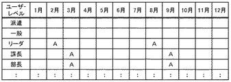
図7A乃至図7Dに、優先月テーブル524のテーブル構成及び格納されるデータの一例を示す。図7Aには、部門の列700と1月の列702と2月の列704と3月の列706と4月の列708と5月の列710と6月の列712と7月の列714と8月の列716と9月の列718と10月の列720と11月の列722と12月の列724とが含まれている。優先度が高い箇所には優先度Aを示す「A」という値が登録されている。空白の箇所は優先度Bに対応している。優先度が低い箇所に優先度Cを示す「C」という値が登録される場合もある。例えば、図7Aの例では、3月の列706の1行目に「A」が登録されていることから、営業部門のユーザには3月に優先度Aが適用される。図6に示した例では、営業部門の優先度Aの倍率は「150%」と登録されており、アイドル時間及び警告表示後の待機時間について、通常の値の150%の値が設定される。図4の例では、例えば営業部門のユーザが「A1」という業務処理を行う場合、通常は5分のアイドル時間が設定されることが示されているが、3月の場合、7.5分(5分×150%)に調整される。同様に、図5の例では、営業部門のユーザには通常は5分の警告表示後の待機時間が設定されることが示されているが、3月の場合、7.5分(5分×150%)に調整される。
7A to 7D show an example of the table configuration of the priority month table 524 and stored data. FIG. 7A illustrates a
図7Aには部門毎の優先月テーブルを示したが、品目毎やユーザ・レベル毎、オーダ毎の優先月テーブルが設けられる場合もある。図7B乃至図7Dに、順に品目毎、ユーザ・レベル毎及びオーダ毎の優先月テーブルの一例を示す。テーブル構成及び格納されるデータは図7Aと類似であり、詳細な説明を省略する。優先月テーブル524には、例えばシステム管理者によってデータが登録される。 Although FIG. 7A shows a priority month table for each department, a priority month table may be provided for each item, each user level, and each order. 7B to 7D show an example of a priority month table for each item, each user level, and each order in order. The table configuration and stored data are similar to those in FIG. 7A, and detailed description thereof is omitted. For example, data is registered in the priority month table 524 by a system administrator.
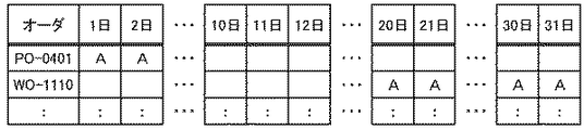
図8A乃至図8Dに、優先日テーブル525のテーブル構成及び格納されるデータの一例を示す。図8Aには、部門の列800と1日の列802と2日の列804と10日の列808と11日の列810と12日の列812と20日の列816と21日の列818と30日の列822と31日の列824とが含まれている。なお、2日の列804と10日の列808との間、12日の列812と20日の列816との間、及び21日の列818と30日の列822との間の「・・・」という印は、日付に対応する列の図示を省略していることを表している。
8A to 8D show an example of the table configuration of the priority date table 525 and stored data. FIG. 8A shows
図7Aに示した部門毎の優先月テーブルと同様、優先度が高い箇所には優先度Aを示す「A」という値が登録されている。空白の箇所は優先度Bに対応している。優先度が低い箇所に優先度Cを示す「C」という値が登録される場合もある。例えば、図8Aの例では、1日の列802の2行目に「A」が登録されていることから、購買部門のユーザには毎月1日に優先度Aが適用される。図6に示した例では、購買部門の優先度Aの倍率は「130%」と登録されており、アイドル時間及び警告表示後の待機時間について、通常の値の130%の値が設定される。図4の例では、例えば購買部門のユーザが「C1」という業務処理を行う場合、通常は5分のアイドル時間が設定されることが示されているが、毎月1日の場合、6.5分(5分×130%)に調整される。同様に、図5の例では、購買部門のユーザには通常は4分の警告表示後の待機時間が設定されることが示されているが、毎月1日の場合、5.2分(4分×130%)に調整される。
As in the priority month table for each department shown in FIG. 7A, a value “A” indicating the priority A is registered at a location with a high priority. Blank portions correspond to priority B. A value “C” indicating the priority C may be registered at a location with a low priority. For example, in the example of FIG. 8A, since “A” is registered in the second row of the
図8Aには部門毎の優先日テーブルを示したが、品目毎やユーザ・レベル毎、オーダ毎の優先日テーブルが設けられる場合もある。図8B乃至図8Dに、順に品目毎、ユーザ・レベル毎及びオーダ毎の優先日テーブルの一例を示す。テーブル構成及び格納されるデータは図8Aと類似であり、詳細な説明を省略する。優先日テーブル525には、例えばシステム管理者によってデータが登録される。 Although FIG. 8A shows the priority date table for each department, a priority date table may be provided for each item, each user level, and each order. 8B to 8D show examples of priority date tables for each item, each user level, and each order in order. The table configuration and stored data are similar to those in FIG. 8A, and detailed description thereof is omitted. For example, data is registered in the priority date table 525 by a system administrator.
図9A乃至図9Dに、優先時間テーブル526のテーブル構成及び格納されるデータの一例を示す。図9Aには、部門の列900と8時台の列902と9時台の列904と10時台の列906と11時台の列908と12時台の列910と13時台の列912と14時台の列914と15時台の列916と16時台の列918と17時台の列920と18時台の列922とが含まれている。
9A to 9D show an example of the table configuration of the priority time table 526 and stored data. FIG. 9A shows a
図7Aに示した部門毎の優先月テーブルと同様、優先度が高い箇所には優先度Aを示す「A」という値が登録されている。空白の箇所は優先度Bに対応している。優先度が低い箇所に優先度Cを示す「C」という値が登録される場合もある。例えば、図9Aの例では、13時台の列912の3行目に「A」が登録されていることから、生産部門のユーザには13時台(13時から14時まで)に優先度Aが適用される。図6に示した例では、生産部門の優先度Aの倍率は「120%」と登録されており、アイドル時間及び警告表示後の待機時間について、通常の値の120%の値が設定される。図4の例では、例えば生産部門のユーザが「F1」という業務処理を行う場合、通常は1分のアイドル時間が設定されることが示されているが、13時台にログインした場合、1.2分(1分×120%)に調整される。同様に、図5の例では、生産部門のユーザには通常は5分の警告表示後の待機時間が設定されることが示されているが、13時台にログインした場合、6分(5分×120%)に調整される。
As in the priority month table for each department shown in FIG. 7A, a value “A” indicating the priority A is registered at a location with a high priority. Blank portions correspond to priority B. A value “C” indicating the priority C may be registered at a location with a low priority. For example, in the example of FIG. 9A, since “A” is registered in the third row of the 13:00
図9Aには部門毎の優先時間テーブルを示したが、品目毎やユーザ・レベル毎、オーダ毎の優先時間テーブルが設けられる場合もある。図9B乃至図9Dに、順に品目毎、ユーザ・レベル毎及びオーダ毎の優先時間テーブルの一例を示す。テーブル構成及び格納されるデータは図9Aと類似であり、詳細な説明を省略する。優先時間テーブル526には、例えばシステム管理者によってデータが登録される。 Although FIG. 9A shows a priority time table for each department, a priority time table may be provided for each item, each user level, and each order. 9B to 9D show examples of priority time tables for each item, each user level, and each order in order. The table configuration and stored data are similar to those in FIG. 9A, and detailed description thereof is omitted. Data is registered in the priority time table 526 by, for example, a system administrator.
図10に、ログ・データ格納部505に格納されるデータの一例を示す。図10の例では、「tobe」というユーザのログ・データが示されている。このように、各ユーザについて、ログイン日時、処理の開始日時、処理の終了日時及びログオフ日時が、ログ・データ生成部503によって記録される。
FIG. 10 shows an example of data stored in the log
図11に、集計期間テーブル533のテーブル構成及び格納されるデータの一例を示す。図11の例には、部門の列1100と開始日の列1102とサイクルの列1104とが含まれている。本テーブルには、集計する対象となるログ・データの範囲が部門毎に登録されている。例えば1行目には、営業部門のユーザのログデータについて、2003年10月1日から半年単位で集計するということが示されている。集計期間テーブル533には、例えばシステム管理者によってデータが登録される。
FIG. 11 shows an example of the table configuration of the total period table 533 and stored data. The example of FIG. 11 includes a
図12に、第1処理時間テーブル535のテーブル構成及び格納されるデータの一例を示す。図12の例には、ユーザの列1200と部門の列1202とA1の列1204とA2の列1206とA3の列1208とC1の列1212とF1の列1216とZZの列1218とが含まれている。なお、A3の列1208とC1の列1212との間、及びC1の列1212とF1の列1216との間の「・・・」という印は、業務処理に対応する列の図示を省略していることを表している。A1の列1204とA2の列1206とA3の列1208とC1の列1212とF1の列1216とには、A1、A2、A3、C1及びF1で表される各業務処理の処理時間の平均値がユーザ毎に登録される。なお、単位は分である。平均値の算出に用いる、各業務処理の処理時間は、ログ・データ格納部505に格納されているログ・データから特定する。また、ユーザ毎の集計期間は、ユーザが属する部門に基づき、集計期間テーブル533に格納されているデータから特定する。例えば、図12の例では、A1の列1204の1行目に「5.2」と登録されている。これは、「iwa」というユーザが「A1」という業務処理を行った結果、平均5.2分かかったことを示している。なお、「iwa」というユーザは購買部門に属するユーザであるため、図11に示した集計期間テーブル533の例に従うと、例えば2003年10月1日から半年間についての平均値である。
FIG. 12 shows an example of the table configuration of the first processing time table 535 and stored data. The example of FIG. 12 includes a
また、ZZの列1218には、警告メッセージ提示後から入力があるまでの時間の平均値がユーザ毎に登録される。図10の例には示していないが、警告メッセージを提示した時間及びその後ユーザから入力があった時間についても、ログ・データに記録されるため、ログ・データ格納部505を参照することにより、平均値を算出することができる。
In the
さらに、図10の例には示していないが、例えばユーザが業務処理を開始し、完了する前に強制的にログオフされた場合には、業務処理が中断されるため、中断日時がログ・データに記録される。そして、ユーザが再びログインして、中断された業務処理を行い完了した場合には、再開日時及び完了日時がログ・データに記録される。このような場合、業務処理の開始日時から中断日時までの時間と再開日時から完了日時までの時間とを合計した値を、当該業務処理にかかった処理時間として扱う。なお、本テーブルに登録されるデータは、設定時間補正部511によって生成される。
Furthermore, although not shown in the example of FIG. 10, for example, when a user starts a business process and forcibly logs off before completion, the business process is interrupted. To be recorded. When the user logs in again and completes the interrupted business process, the restart date / time and completion date / time are recorded in the log data. In such a case, a value obtained by summing the time from the start date / time to the suspension date / time of the business process and the time from the restart date / time to the completion date / time is treated as the processing time required for the business process. Note that the data registered in the table is generated by the set
図13に、第2処理時間テーブル537のテーブル構成及び格納されるデータの一例を示す。図13の例には、部門の列1300とA1の列1302とA2の列1304とA3の列1306とC1の列1310とF1の列1314とZZの列1316とが含まれている。なお、A3の列1306とC1の列1310との間、及びC1の列1310とF1の列1314との間の「・・・」という印は、業務処理に対応する列の図示を省略していることを表している。本テーブルには、図12に示したユーザ毎の平均処理時間に基づき計算された部門毎の平均処理時間が登録される。本テーブルに格納されるデータは、設定時間補正部511によって生成される。
FIG. 13 shows an example of the table configuration of the second processing time table 537 and stored data. The example of FIG. 13 includes a
図14に、判定基準テーブル531のテーブル構成及び格納されるデータの一例を示す。図14の例には、差の列1400と調整内容の列1402とが含まれている。本テーブルには、アイドル時間及び警告表示後の待機時間を調整するためのデータが格納されている。具体的には、部門及び業務処理毎に、第2処理時間テーブル537に登録された平均値とアイドル時間テーブル521に格納されているアイドル時間とを比較し、それらの差に応じて、本テーブルに設定された内容に従い、アイドル時間を更新する。例えば、営業部門のユーザの「A1」という業務処理の平均処理時間が、第2処理時間テーブル537に「4.7(分)」と登録されており、一方で、営業部門のユーザの「A1」という業務処理のアイドル時間が、アイドル時間テーブル521に「5(分)」と登録されていた場合、その差は−0.3(4.7−5.0)と算出される。図14に示した例に従うと、差が−0.5から+0.5までに該当するため、アイドル時間は更新されない。
FIG. 14 shows an example of the table configuration of the determination criterion table 531 and stored data. The example of FIG. 14 includes a
同様に、第2処理時間テーブル537に登録された平均値(ZZの列1316の値)と待機時間テーブル522に格納されている警告表示後の待機時間とを部門毎に比較し、それらの差に応じて、本テーブルに設定された内容に従い、警告表示後の待機時間を更新する。 Similarly, the average value (value in the ZZ column 1316) registered in the second processing time table 537 and the standby time after the warning display stored in the standby time table 522 are compared for each department, and the difference between them is compared. Accordingly, the waiting time after the warning is displayed is updated according to the contents set in this table.
図15に、ユーザ端末3のバックアップ・データ格納部35のテーブル構成及び格納されるデータの一例を示す。図15の例には、ユーザIDの行1500と画面IDの行1502と入力項目1の行1504と入力項目2の行1506と入力項目3の行1508と入力項目4の行1510と入力項目5の行1512と入力項目6の行1514と入力項目7の行1516と入力項目8の行1518と入力項目9の行1520と入力項目999の行1524とが含まれている。なお、入力項目9の行1520と入力項目999の行1524との間の「:」という印は、入力項目10乃至998に対応する行の図示を省略していることを表している。図15には、例えば「tobe」というユーザが、画面ID「A1-1」で示される画面の各項目に対して入力を行い、入力項目1乃至7までの入力を終えた時点で強制的なログオフがなされた場合に、バックアップ・データ格納部35に格納されるデータの例が示されている。このようなデータを、「tobe」というユーザの再ログインに応じて画面表示することにより、ユーザは入力処理を初めからやり直さなくて済む。なお、このようなデータは、バックアップ処理部33により生成され、バックアップ・データ格納部35に格納される。
FIG. 15 shows an example of the table configuration of the backup
図16乃至図21を用いて、図1に示したシステムの処理について説明する。まず、ユーザ端末3のERPクライアント30は、ユーザの操作に従い、表示装置にログイン画面を表示する(図16:ステップS1)。また、ERPクライアント30は、ユーザからのログイン・データの入力を受け付け、当該ログイン・データをアプリケーション・サーバ5に送信する(ステップS3)。アプリケーション・サーバ5のログイン管理部507は、ユーザ端末3からログイン・データを受信し、図示しないワーク・メモリ領域等の記憶装置に一旦格納する(ステップS5)。また、ログイン管理部507は、接続ユーザ数格納部515を参照して接続ユーザ数を確認する(ステップS7)。そして、ログイン管理部507は、接続ユーザ数が最大になっているか判定する(ステップS9)。最大であると判定された場合(ステップS9:Yesルート)、後に述べるステップS15の処理に移行する。一方、最大ではないと判定された場合(ステップS9:Noルート)、ログイン管理部507は、ユーザ管理テーブル509を参照してユーザ認証処理を行う(ステップS11)。また、ログイン管理部507は、ユーザ認証処理の結果に基づき、当該ユーザのログインが可能であるか判定する(ステップS13)。ログインが可能であると判定された場合(ステップS13:Yesルート)、端子Aを介して図17の処理に移行する。一方、ログインが可能ではないと判定された場合(ステップS13:Noルート)、ログイン管理部507は、ログイン不可を示すデータをユーザ端末3に送信する(ステップS15)。ユーザ端末3のERPクライアント30は、ログイン不可を示すデータをアプリケーション・サーバ5から受信し、ログインできなかったことを表すメッセージを表示装置に表示する(ステップS17)。そして、ステップS1の処理に戻る。このように、ユーザが認証されない場合に加えて、接続ユーザ数が最大になっている場合にも、ユーザはログインすることができないようになっている。
The processing of the system shown in FIG. 1 will be described with reference to FIGS. First, the
図17に、端子Aを介して移行した後の処理を示す。まず、アプリケーション・サーバ5のログイン管理部507は、ログイン処理を行う(図17:ステップS21)。また、ログイン管理部507は、接続ユーザ数格納部515に格納されている接続ユーザ数を更新する(ステップS23)。すなわち1増やす。次に、ログイン管理部507は、ログインさせたユーザのユーザIDに基づき、当該ユーザに関するデータが未確定入力データ格納部513に格納されているか確認する(ステップS25)。そして、ログイン管理部507は、ステップS25の処理結果に基づき、ログインさせたユーザが新規処理ユーザであるか判定する(ステップS27)。当該ユーザに関するデータが未確定入力データ格納部513に格納されていなければ、新規処理ユーザである。
FIG. 17 shows the processing after the transition through the terminal A. First, the
新規処理ユーザであると判定された場合(ステップS27:Yesルート)、ログイン管理部507は、例えばメニュー画面等の新規処理画面IDを抽出する(ステップS29)。例えばERPサーバ処理部501に含まれる設定データから抽出する。そして後に述べるステップS33の処理に移行する。一方、新規処理ユーザではないと判定された場合(ステップS27:Noルート)、ログイン管理部507は、未確定入力データ格納部513に格納されていた当該ユーザに関するデータから、入力中画面IDを抽出する(ステップS31)。入力中画面IDとは、強制的にログオフがなされる際、ユーザ端末3の表示装置に表示されていた画面のIDである。次に、ログイン管理部507は、アイドル時間設定処理を行う(ステップS33)。アイドル時間設定処理の詳細については後に述べるが、処理結果として、今回のログインに対応するアイドル時間及び警告表示後の待機時間が決定される。
When it is determined that the user is a new processing user (step S27: Yes route), the
そして、ログイン管理部507は、抽出されている画面IDをユーザ端末3に送信する(ステップS35)。ユーザ端末3のERPクライアント30は、画面IDをアプリケーション・サーバ5から受信する(ステップS37)。また、ERPクライアント30は、受信した画面ID及びバックアップ・データ格納部35に格納されているデータを用いて、表示装置に画面を表示する(ステップS39)。具体的には、まず、受信した画面IDに対応する画面を特定する。さらに、バックアップ・データ格納部35から、受信した画面IDに対応する入力項目データを抽出する。そして、入力欄等に対応する入力項目データが埋め込まれた画面のデータを生成し、表示装置に表示する。なお、新規処理画面の画面IDを受信した場合には、対応する入力項目データがバックアップ・データ格納部35に格納されていないため、入力項目データが埋め込まれていない画面をそのまま表示する。入力中画面IDを受信した場合には、バックアップ・データ格納部35に格納されているデータを用いて画面表示を行うことにより、ユーザに前回の続きから業務処理を行わせることができる。
Then, the
一方、アプリケーション・サーバ5のログイン管理部507は、ステップS35において画面IDを送信した後、無入力時間の計測を開始する(ステップS41)。無入力時間とは、ユーザから何らの入力もなされない時間である。そして、処理は端子B及び端子Cを介して図18の処理に移行する。
On the other hand, the
図18に、端子B及び端子Cを介して移行した後の処理を示す。まず、ユーザ端末3のERPクライアント30は、ユーザからの入力受け付け待ちの状態になっており、ユーザから何らかの入力があれば、アプリケーション・サーバ5に入力イベントを通知する(図18:ステップS51)。なお、例えば「登録ボタン」のクリック等、所定の入力イベントが発生した場合には、通知データに実データが含まれる。アプリケーション・サーバ5のログイン管理部507は、ユーザからの入力があったか判定する(ステップS53)。入力があったと判定された場合(ステップS53:Yesルート)、端子Dを介して図19の処理に移行する。一方、入力がなかったと判定された場合(ステップS53:Noルート)、ログイン管理部507は、ステップS41(図17)において計測を開始した無入力時間が、ステップS33(図17)において決定されたアイドル時間を超えたか判定する(ステップS55)。超えていないと判定された場合(ステップS55:Noルート)、ステップS53の処理に戻る。一方、無入力時間がアイドル時間を超えたと判定された場合(ステップS55:Yesルート)、ログイン管理部507は、警告メッセージ・データをユーザ端末3に送信する(ステップS57)。なお、ステップS57において警告メッセージ・データを生成してもよいし、予め用意しておいた警告メッセージ・データを送信してもよい。また、警告メッセージ・データがユーザ端末3に保持されている場合には、警告メッセージを表示させるための指示データをユーザ端末3に送信する。また、ログイン管理部507は、再び無入力時間の計測を開始する(ステップS59)。
FIG. 18 shows a process after the transition through the terminal B and the terminal C. First, the
一方、ユーザ端末3のERPクライアント30に含まれるログイン制御部31は、警告メッセージ・データをアプリケーション・サーバ5から受信すると、表示装置に表示する(ステップS61)。そして、ユーザ端末3のERPクライアント30は、再びユーザからの入力受け付け待ちの状態になり、ユーザから何らかの入力があれば、アプリケーション・サーバ5に入力イベントを通知する(ステップS63)。なお、例えば「登録ボタン」のクリック等、所定の入力イベントが発生した場合には、通知データに実データが含まれる。アプリケーション・サーバ5のログイン管理部507は、ユーザからの入力があったか判定する(ステップS65)。入力があったと判定された場合(ステップS65:Yesルート)、端子Dを介して図19の処理に移行する。一方、入力がなかったと判定された場合(ステップS65:Noルート)、ログイン管理部507は、ステップS59において計測を開始した無入力時間が、ステップS33(図17)において決定された警告表示後の待機時間を超えたか判定する(ステップS67)。超えていないと判定された場合(ステップS67:Noルート)、ステップS65の処理に戻る。一方、無入力時間が警告表示後の待機時間を超えたと判定された場合(ステップS67:Yesルート)、ログイン管理部507は、警告表示後の待機時間を超えて入力をしなかったユーザのユーザIDと、ユーザ端末3の表示装置に表示されている画面の画面IDとを対応付けて未確定入力データ格納部513に格納する(ステップS69)。なお、ERPサーバ処理部501に問い合わせることにより、ユーザID及び画面IDを取得し、画面IDを入力中画面IDとして未確定入力データ格納部513に格納する。
On the other hand, when receiving the warning message data from the
また、ログイン管理部507は、ログオフ通知データをユーザ端末3に送信する(ステップS71)。なお、ステップS71においてログオフ通知データを生成してもよいし、予め用意しておいたログオフ通知データを送信してもよい。ユーザ端末3のERPクライアント30に含まれるログイン制御部31は、ログオフ通知データをアプリケーション・サーバ5から受信する(ステップS73)。ユーザ端末3のERPクライアント30に含まれるバックアップ処理部33は、ログイン制御部31がログオフ通知データを受信したことを検出すると、未確定入力データをバックアップ・データ格納部35に格納する(ステップS75)。例えば図15に示したようなデータが格納される。そして、処理は端子Eを介してステップS1(図16)に戻る。
Also, the
一方、アプリケーション・サーバ5のログイン管理部507は、ステップS71においてログオフ通知データを送信した後、ログオフ処理を行う(ステップS77)。また、ログイン管理部507は、接続ユーザ数格納部515に格納されている接続ユーザ数を更新する(ステップS79)。すなわち1減らす。また、ログイン管理部507と連動しているERPサーバ処理部501は、ユーザがログオフされたことをログ・データ生成部503に通知し、ログ・データ生成部503は当該ログオフに係るログ・データをログ・データ格納部505に記録する(ステップS81)。そして処理を終了する。
On the other hand, the
図19に、端子Dを介して移行した後の処理を示す。まず、アプリケーション・サーバ5のERPサーバ処理部501は、ユーザからの入力がログオフを指示するものであったか判定する(図19:ステップS91)。ログオフを指示するものであったと判定された場合(ステップS91:Yesルート)、端子Fを介してステップS77(図18)の処理に移行する。一方、ログオフを指示するものではなかったと判定された場合(ステップS91:Noルート)、ERPサーバ処理部501は、ユーザ端末3から送信された通知データに実データが含まれていたか判定する(ステップS93)。通知データに実データが含まれていなかったと判定された場合(ステップS93:Noルート)、端子Gを介してステップS41(図17)の処理に戻る。一方、通知データに実データが含まれていたと判定された場合(ステップS93:Yesルート)、ERPサーバ処理部501は、実データに対応した処理を行う(ステップS95)。処理結果をユーザ端末3に送信する場合もある。そして、ERPサーバ処理部501は、ユーザ端末3の表示画面に表示されている画面に係る一連の処理が終了したか判定する(ステップS97)。画面の処理が終了していないと判定された場合(ステップS97:Noルート)、端子Gを介してステップS41(図17)の処理に戻る。一方、画面の処理が終了したと判定された場合(ステップS97:Yesルート)、ログ・データ生成部503は当該画面の処理に係るログ・データをログ・データ格納部505に記録する(ステップS99)。また、ERPサーバ処理部501は、ユーザ端末3の表示画面に次に表示させる画面のIDを特定する(ステップS101)。そして、端子Hを介してステップS33(図17)の処理に移行する。
FIG. 19 shows a process after the transition through the terminal D. First, the ERP
このようにして、警告表示後の待機時間を超えて入力をしなかったユーザを強制的にログオフさせることにより、ユーザ・ライセンスの利用効率を向上させることができる。また、ログオフ直前に端末の表示装置に表示されていた画面を再び表示することで、ユーザの負荷を減らし、業務効率を向上させることができる。 In this way, the user license usage efficiency can be improved by forcibly logging off the user who has not entered the waiting time after the warning is displayed. Further, by displaying again the screen that was displayed on the display device of the terminal immediately before the logoff, it is possible to reduce the load on the user and improve the work efficiency.
なお、ERPパッケージによっては、ウェブ(Web)技術を利用し、ユーザ端末に専用のクライアント・プログラムの設置を必要としないものもある。このような場合、例えば、ユーザが文字を1つ入力しただけでは、サーバ側に通知がなされることはない。従って、例えば「登録ボタン」のクリック等により、入力又は選択データがユーザ端末から送信され、そのような入力又は選択データをサーバ側で受信した場合に、ユーザからの入力があったと判定する。一方、アイドル時間や警告表示後の警告表示後の待機時間を超えて入力又は選択データを受信しない状態が続いた場合には、ユーザからの入力がなされなかったものと判定する。 Some ERP packages use web technology and do not require installation of a dedicated client program in the user terminal. In such a case, for example, if the user only inputs one character, the server side is not notified. Therefore, for example, when the input or selection data is transmitted from the user terminal by clicking the “registration button” or the like and the input or selection data is received on the server side, it is determined that there is an input from the user. On the other hand, if the state where the input or selection data is not received exceeds the idle time or the standby time after the warning is displayed, it is determined that the input from the user has not been made.
また、警告メッセージをユーザに提示したり、ユーザを強制的にログオフさせた後にユーザ端末にログイン画面を表示させる場合、ユーザ端末からの要求を受けることなく、サーバ側から一方的にユーザ端末にデータを送信することはできないため、例えば、Webページ・データに、定期的に画面をリフレッシュさせるためのタグを組み込んでおく。また、ログオフの時点で未だサーバ側に送信されていないデータをユーザ端末の記憶装置に保存することは困難である。そのため、ログオフ直前に端末の表示装置に表示されていた画面(入力中のデータを含まず)の画面IDと、ユーザIDとを対応付けてサーバ側で保持しておき(又はクッキーでユーザ端末側に保持しておき)、再ログインに応じてログオフ直前の画面を表示させるようにする。このようにすることで、Web技術を利用したERPパッケージにも本発明の技術を適用することができる。 In addition, when a login message is displayed on the user terminal after a warning message is presented to the user or the user is forcibly logged off, data is unilaterally transmitted from the server side to the user terminal without receiving a request from the user terminal. Can not be transmitted, for example, a tag for periodically refreshing the screen is incorporated in the Web page data. In addition, it is difficult to save data that has not been transmitted to the server side at the time of logoff in the storage device of the user terminal. Therefore, the screen ID of the screen (not including the data being input) displayed on the terminal display device immediately before log off and the user ID are associated with each other and held on the server side (or the user terminal side with a cookie). And display the screen immediately before logoff in response to re-login. By doing in this way, the technology of the present invention can be applied to an ERP package using Web technology.
図20を用いて、アイドル時間設定処理(図17:ステップS33)の詳細について説明する。なお、本実施の形態においては、優先度の設定を、部門、品目、ユーザ・レベル及びオーダのいずれか1つに基づき特定する又は標準と特定する。また、優先月テーブル524、優先日テーブル525及び優先時間テーブル526のいずれか1つに優先度が設定されているものとする。まず、アプリケーション・サーバ5のログイン管理部507は、設定データ格納部520の優先月テーブル524と優先日テーブル525と優先時間テーブル526とのいずれか1つに設定されている優先度のデータを確認する(図20:ステップS111)。そして、ログイン管理部507は、優先度が部門毎に設定されているか判定する(ステップS113)。優先度が部門毎に設定されていると判定された場合(ステップS113:Yesルート)、ログイン管理部507は、現在日時及びユーザが属する部門に基づき優先設定を特定する(ステップS115)。優先設定として、例えば「A」と特定する。そして、後に述べるステップS133の処理に移行する。
Details of the idle time setting process (FIG. 17: step S33) will be described with reference to FIG. In the present embodiment, the priority setting is specified based on any one of a department, an item, a user level, and an order, or specified as a standard. Further, it is assumed that the priority is set in any one of the priority month table 524, the priority date table 525, and the priority time table 526. First, the
一方、優先度が部門毎に設定されていないと判定された場合(ステップS113:Noルート)、ログイン管理部507は、優先度が品目毎に設定されているか判定する(ステップS117)。優先度が品目毎に設定されていると判定された場合(ステップS117:Yesルート)、ログイン管理部507は、現在日時及びユーザの担当品目に基づき優先設定を特定する(ステップS119)。そして、後に述べるステップS133の処理に移行する。
On the other hand, when it is determined that the priority is not set for each department (step S113: No route), the
一方、優先度が品目毎に設定されていないと判定された場合(ステップS117:Noルート)、ログイン管理部507は、優先度がユーザ・レベル毎に設定されているか判定する(ステップS121)。優先度がユーザ・レベル毎に設定されていると判定された場合(ステップS121:Yesルート)、ログイン管理部507は、現在日時及びユーザの役職レベルに基づき優先設定を特定する(ステップS123)。そして、後に述べるステップS133の処理に移行する。
On the other hand, when it is determined that the priority is not set for each item (step S117: No route), the
一方、優先度がユーザ・レベル毎に設定されていないと判定された場合(ステップS121:Noルート)、ログイン管理部507は、優先度がオーダ毎に設定されているか判定する(ステップS125)。優先度がオーダ毎に設定されていないと判定された場合(ステップS125:Noルート)、ログイン管理部507は、優先設定を標準と特定する(ステップS127)。そして、後に述べるステップS133の処理に移行する。
On the other hand, when it is determined that the priority is not set for each user level (step S121: No route), the
一方、優先度がオーダ毎に設定されていると判定された場合(ステップS125:Yesルート)、ログイン管理部507は、ユーザ端末3の表示装置に表示させている画面のIDに基づき、オーダを特定する(ステップS129)。ERPサーバ処理部501に問い合わせる場合もある。また、ログイン管理部507は、現在日時及びオーダに基づき優先設定を特定する(ステップS131)。
On the other hand, when it is determined that the priority is set for each order (step S125: Yes route), the
次に、ログイン管理部507は、ユーザ端末3の表示装置に表示させている画面のIDに基づき、業務処理を特定する(ステップS133)。例えば画面IDが「A1−1」の場合、業務処理は「A1」であると特定することができる。対応表等を用いて特定してもよい。また、ログイン管理部507は、ステップS133において特定した業務処理と、ユーザが属する部門とに基づきアイドル時間テーブル521を参照し、該当するアイドル時間を抽出して図示しないワーク・メモリ領域等の記憶装置に一旦格納する(ステップS135)。例えば「5(分)」を抽出する。さらに、ログイン管理部507は、ユーザが属する部門に基づき待機時間テーブル522を参照し、該当する警告表示後の待機時間を抽出して図示しないワーク・メモリ領域等の記憶装置に一旦格納する(ステップS137)。例えば「4(分)」を抽出する。
Next, the
次に、ログイン管理部507は、上で特定した優先設定に基づき優先率テーブル523から優先率を抽出する(ステップS139)。例えば「120%」を抽出する。そして、ログイン管理部507は、ステップS135において抽出したアイドル時間にステップS139において抽出した優先率を掛けた値と、ステップS137において抽出した警告表示後の待機時間にステップS139において抽出した優先率を掛けた値とを算出し、図示しないワーク・メモリ領域等の記憶装置に一旦格納する(ステップS141)。例えば「6分(5分×120%)」と「4.8分(4分×120%)」とが算出される。そして元の処理に戻る。このようにしてアイドル時間設定処理が行われ、今回のログインに対応するアイドル時間及び警告表示後の待機時間が決定される。
Next, the
なお、アイドル時間及び警告表示後の待機時間の決定においては、基準となるデータがアイドル時間テーブル521及び待機時間テーブル522に格納されており、これを用いて時間を決定しているが、本実施の形態においては、アイドル時間テーブル521及び待機時間テーブル522に格納されているデータについても適宜補正するようになっている。そのような設定時間補正処理について、図21を用いて説明する。まず、設定時間補正部511は、ログ・データ格納部505及び集計期間テーブル533のデータに基づき、第1処理時間テーブル535のデータを生成し、格納する(ステップS151)。例えば半年分のログ・データに基づき、ユーザ毎に各業務処理の処理時間の平均値を算出し、第1処理時間テーブル535に格納する。さらに、設定時間補正部511は、ステップS151において格納した第1処理時間テーブル535のデータに基づき、第2処理時間テーブル537のデータを生成し、格納する(ステップS153)。すなわち、ユーザ毎の集計データに基づき、部門毎の集計データを生成する。
In the determination of the idle time and the standby time after the warning is displayed, reference data is stored in the idle time table 521 and the standby time table 522, and the time is determined using this data. In this embodiment, the data stored in the idle time table 521 and the standby time table 522 are also corrected as appropriate. Such a set time correction process will be described with reference to FIG. First, the set
そして、設定時間補正部511は、ステップS153において格納した第2処理時間テーブル537のデータと、アイドル時間テーブル521及び待機時間テーブル522のデータとを比較する(ステップS155)。また、設定時間補正部511は、ステップS155における比較結果と、判定基準テーブル531のデータとに基づき、アイドル時間テーブル521及び待機時間テーブル522を更新する(ステップS157)。具体例は上の図14の説明において示したとおりである。
Then, the set
このようにして設定時間補正処理が行われる。これにより、例えばシステム管理者が設定した初期値が適切でなかった場合や、ユーザが操作に慣れてきて、基準となる時間に余裕があり過ぎるようになってしまった場合など、基準となる時間を補正することができる。 In this way, the set time correction process is performed. As a result, for example, when the initial value set by the system administrator is not appropriate or when the user has become accustomed to the operation and the reference time has become too large, the reference time Can be corrected.
以上本発明の実施の形態について説明したが、本発明はこれに限定されるものではない。例えば、図3乃至図6、図7A乃至図7D、図8A乃至図8D、図9A乃至図9D、及び図11乃至図15に示したテーブル構成は一例であって、同様のデータを格納するためであれば別の構成を採用するようにしてもよいし、必要に応じて項目を追加又は削除してもよい。また、図10に示したログ・データも一例であって、ログに記録する要素は図10に示した要素に限られない。また、図1に示したアプリケーション・サーバ及びユーザ端末の機能ブロック構成は一例であって、実際のプログラム・モジュール構成とは異なる場合がある。また、図2に示したコンピュータの機能ブロック図も一例であって、実際のハードウェア構成とは異なる場合もある。また、アプリケーション・サーバが複数のサーバやコンピュータによって構成されていてもよい。さらに、図16乃至図21に示した処理フローも一例であって、同様の処理結果が得られる範囲において処理の順序を入れ替えてもよいし、必要に応じてステップを追加又は削除してもよい。 Although the embodiment of the present invention has been described above, the present invention is not limited to this. For example, the table configurations shown in FIGS. 3 to 6, 7A to 7D, 8A to 8D, 9A to 9D, and 11 to 15 are examples, and are for storing similar data. If so, another configuration may be adopted, and items may be added or deleted as necessary. The log data shown in FIG. 10 is also an example, and the elements recorded in the log are not limited to the elements shown in FIG. The functional block configurations of the application server and the user terminal shown in FIG. 1 are merely examples, and may differ from the actual program module configuration. The functional block diagram of the computer shown in FIG. 2 is also an example, and may be different from the actual hardware configuration. Further, the application server may be composed of a plurality of servers and computers. Furthermore, the processing flow shown in FIGS. 16 to 21 is also an example, and the processing order may be changed within a range in which similar processing results are obtained, and steps may be added or deleted as necessary. .
(付記1)
ユーザによるログインが必要であり且つ複数種類の業務を取り扱うコンピュータ・システムにより実行されるログイン管理プログラムであって、
前記ユーザにより選択された業務と前記ユーザの属性とに基づき、所定の許容時間を決定し、記憶装置に格納する許容時間決定ステップと、
前記記憶装置に格納された前記所定の許容時間を超えて、前記選択された業務に係るデータが未入力又は未受信であることを検出した場合、前記ユーザを強制的にログオフさせるログオフ・ステップと、
を実行させるためのログイン管理プログラム。
(Appendix 1)
A login management program executed by a computer system that requires login by a user and handles a plurality of types of work,
An allowable time determination step of determining a predetermined allowable time based on the task selected by the user and the attribute of the user, and storing the predetermined allowable time in a storage device;
A log-off step for forcibly logging off the user when it is detected that the data relating to the selected task has not been input or received beyond the predetermined allowable time stored in the storage device; and ,
A login management program for running.
(付記2)
前記ログオフ・ステップが、前記ユーザが操作する端末に表示させている画面に関するデータを、前記ユーザに対応付けて画面データ記憶部に格納するステップを含み、
強制的にログオフされた前記ユーザによるログインに応じて、前記画面データ記憶部に格納された前記画面に関するデータを用いて、前記ユーザが操作する端末に前記画面を表示させるステップ
をさらに含む付記1記載のログイン管理プログラム。
(Appendix 2)
The logoff step includes a step of storing data relating to a screen displayed on a terminal operated by the user in a screen data storage unit in association with the user,
The method according to
(付記3)
前記所定の許容時間が、アイドル時間と第1の待機時間とを含み、
前記アイドル時間を超えて、前記選択された業務に係るデータが未入力又は未受信であることを検出した場合、前記ユーザに警告するためのデータを前記ユーザが操作する端末に表示させるステップ
をさらに含む付記1記載のログイン管理プログラム。
(Appendix 3)
The predetermined allowable time includes an idle time and a first waiting time;
A step of displaying data for warning the user on a terminal operated by the user when it is detected that the data related to the selected job is not input or not received beyond the idle time; A login management program according to
(付記4)
利用実績データに基づき、所定のアイドル時間及び所定の第1の待機時間の少なくともいずれかを調整し、調整データ格納部に格納する調整ステップ
をさらに含み、
前記許容時間決定ステップにおいて、
前記調整データ格納部に格納されたデータに基づき、前記所定の許容時間を決定することを特徴とする
付記3記載のログイン管理プログラム。
(Appendix 4)
An adjustment step of adjusting at least one of the predetermined idle time and the predetermined first waiting time based on the usage record data, and storing the adjusted idle data in the adjustment data storage unit;
In the allowable time determining step,
The login management program according to
(付記5)
前記調整ステップが、
前記利用実績データに基づき、前記ユーザが属する業務部門及び前記ユーザが選択し得る業務毎の処理時間の平均値を所定の集計期間について算出し、処理時間テーブルに登録するステップと、
前記利用実績データに基づき、前記ユーザに警告するためのデータを前記ユーザが操作する端末に表示させてから、前記選択された業務に係るデータの入力又は受信を検出するまでの第2の待機時間の平均値を前記所定の集計期間について前記ユーザが属する業務部門毎に算出し、前記処理時間テーブルに登録するステップと、
前記処理時間テーブルに登録された前記処理時間の平均値と、前記所定のアイドル時間との差に応じて、前記所定のアイドル時間を調整するステップと、
前記処理時間テーブルに登録された前記第2の待機時間の平均値と、前記所定の第1の待機時間との差に応じて、前記所定の第1の待機時間を調整するステップと
を含む付記4記載のログイン管理プログラム。
(Appendix 5)
The adjusting step comprises:
Calculating an average value of processing time for each business that the user can select and the business department to which the user belongs based on the usage record data, and registering it in a processing time table;
A second waiting time from when data for warning the user is displayed on the terminal operated by the user based on the usage record data until detection of input or reception of data related to the selected task Calculating the average value for each business department to which the user belongs for the predetermined counting period, and registering it in the processing time table;
Adjusting the predetermined idle time according to a difference between an average value of the processing times registered in the processing time table and the predetermined idle time;
And adjusting the predetermined first waiting time according to a difference between the average value of the second waiting time registered in the processing time table and the predetermined first waiting time. 4. The login management program according to 4.
(付記6)
前記許容時間決定ステップが、
前記ユーザが属する業務部門と、前記ユーザの担当業務に係る品目と、前記ユーザの役職レベルと、前記業務に係るオーダと、ログイン日時とのうち少なくともいずれか1つに応じて設定された優先度に基づき、所定のアイドル時間及び所定の第1の待機時間の少なくともいずれかを調整するステップと、
調整された前記アイドル時間及び前記第1の待機時間の少なくともいずれかに基づき、前記所定の許容時間を決定するステップと、
を含む付記3記載のログイン管理プログラム。
(Appendix 6)
The allowable time determining step includes:
Priority set in accordance with at least one of the business department to which the user belongs, the item related to the business in charge of the user, the job title level of the user, the order related to the business, and the login date and time Adjusting at least one of a predetermined idle time and a predetermined first waiting time based on
Determining the predetermined allowable time based on at least one of the adjusted idle time and the first waiting time;
The login management program according to
(付記7)
前記ログオフ・ステップが、
前記ユーザにより入力されたデータを保存すべきことを前記ユーザが操作する端末に通知するステップ
をさらに含む付記2記載のログイン管理プログラム。
(Appendix 7)
The logoff step comprises:
The login management program according to
(付記8)
ユーザによるログインが必要であり且つ複数種類の業務を取り扱うコンピュータ・システムにより実行されるログイン管理プログラムを格納した記録媒体であって、
前記ログイン管理プログラムは、
前記ユーザにより選択された業務と前記ユーザの属性とに基づき、所定の許容時間を決定し、記憶装置に格納するステップと、
前記記憶装置に格納された前記所定の許容時間を超えて、前記選択された業務に係るデータが未入力又は未受信であることを検出した場合、前記ユーザを強制的にログオフさせるログオフ・ステップと、
を前記コンピュータ・システムに実行させることを特徴とする記録媒体。
(Appendix 8)
A recording medium storing a login management program that is executed by a computer system that requires login by a user and handles a plurality of types of work,
The login management program includes:
Determining a predetermined permissible time based on the task selected by the user and the user's attributes, and storing in a storage device;
A log-off step for forcibly logging off the user when it is detected that the data relating to the selected task has not been input or received beyond the predetermined allowable time stored in the storage device; and ,
That the computer system executes.
(付記9)
ユーザによるログインが必要であり且つ複数種類の業務を取り扱うログイン管理装置であって、
前記ユーザにより選択された業務と前記ユーザの属性とに基づき、所定の許容時間を決定し、記憶装置に格納する手段と、
前記記憶装置に格納された前記所定の許容時間を超えて、前記選択された業務に係るデータが未入力又は未受信であることを検出した場合、前記ユーザを強制的にログオフさせる手段と、
を有するログイン管理装置。
(Appendix 9)
A login management apparatus that requires login by a user and handles a plurality of types of work,
Means for determining a predetermined allowable time based on the task selected by the user and the attribute of the user and storing it in a storage device;
Means for forcibly logging off the user when it is detected that the data relating to the selected task is not input or not received beyond the predetermined allowable time stored in the storage device;
A login management device.
(付記10)
ユーザによるログインが必要であり且つ複数種類の業務を取り扱うコンピュータ・システムにより実行されるログイン管理方法であって、
前記ユーザにより選択された業務と前記ユーザの属性とに基づき、所定の許容時間を決定し、記憶装置に格納するステップと、
前記記憶装置に格納された前記所定の許容時間を超えて、前記選択された業務に係るデータが未入力又は未受信であることを検出した場合、前記ユーザを強制的にログオフさせるステップと、
を含むログイン管理方法。
(Appendix 10)
A login management method executed by a computer system that requires login by a user and handles a plurality of types of work,
Determining a predetermined permissible time based on the task selected by the user and the user's attributes, and storing in a storage device;
Forcing the user to log off if it is detected that the data relating to the selected task is not entered or not received beyond the predetermined allowable time stored in the storage device;
Login management method including.
1 社内LAN 3 ユーザ端末
5 アプリケーション・サーバ
30 ERPクライアント 31 ログイン制御部
33 バックアップ処理部 35 バックアップ・データ格納部
501 ERPサーバ処理部 503 ログ・データ生成部
505 ログ・データ格納部 507 ログイン管理部
509 ユーザ管理テーブル 511 設定時間補正部
513 未確定入力データ格納部 515 接続ユーザ数格納部
520 設定データ格納部 521 アイドル時間テーブル
522 待機時間テーブル 523 優先率テーブル
524 優先月テーブル 525 優先日テーブル
526 優先時間テーブル 530 補正基準データ格納部
531 判定基準テーブル 533 集計期間テーブル
535 第1処理時間テーブル 537 第2処理時間テーブル
1
Claims (5)
前記ユーザにより選択された業務と前記ユーザの属性とに基づき、アイドル時間と第一の待機時間とを特定し、記憶装置に格納するステップと、
前記ユーザが属する業務部門と、前記ユーザの担当業務に係る品目と、前記ユーザの役職レベルと、前記業務に係るオーダとのうちいずれか1つと、ログイン日時とに応じて設定された優先度に基づき、特定された前記アイドル時間と前記第1の待機時間とを補正し、前記記憶装置に格納するステップと、
前記記憶装置に格納された前記アイドル時間を超えて、前記選択された業務に係るデータが未入力である場合、前記ユーザに警告するためのデータを前記ユーザが操作する端末に表示させるステップと、
前記記憶装置に格納された前記アイドル時間の経過後、前記記憶装置に格納された前記第一の待機時間をさらに経過して、前記選択された業務に係るデータが未入力である場合、前記ユーザを強制的にログオフさせるログオフ・ステップと、
を実行させるためのログイン管理プログラム。 A login management program executed by a computer system that requires login by a user and handles a plurality of types of work,
Identifying an idle time and a first waiting time based on the work selected by the user and the attributes of the user, and storing in a storage device;
A business unit in which the user belongs, and materials relating to their operations of the user, and title level of the user, one one of the order according to the work, to the priority set in response to the login date and time Correcting the specified idle time and the first waiting time based on the storage time in the storage device;
A step beyond the idle time stored in the storage device, the data relating to the selected business be a non-input, to display the data to alert the user to the terminal that the user operates,
After the elapse of the idle time stored in the storage device, when the first standby time stored in the storage device further elapses and the data relating to the selected job is not input , the user Log off step to force log off,
A login management program for running.
強制的にログオフされた前記ユーザによるログインに応じて、前記画面データ記憶部に格納された前記画面に関するデータを用いて、前記ユーザが操作する端末に前記画面を表示させるステップ
をさらに含む請求項1記載のログイン管理プログラム。 The logoff step includes a step of storing data relating to a screen displayed on a terminal operated by the user in a screen data storage unit in association with the user,
The method further comprises a step of displaying the screen on a terminal operated by the user using data relating to the screen stored in the screen data storage unit in response to a login by the user who is forcibly logged off. The login management program described.
前記ログイン管理プログラムは、
前記ユーザにより選択された業務と前記ユーザの属性とに基づき、アイドル時間と第一の待機時間とを特定し、記憶装置に格納するステップと、
前記ユーザが属する業務部門と、前記ユーザの担当業務に係る品目と、前記ユーザの役職レベルと、前記業務に係るオーダとのうちいずれか1つと、ログイン日時とに応じて設定された優先度に基づき、特定された前記アイドル時間と前記第1の待機時間とを補正し、前記記憶装置に格納するステップと、
前記記憶装置に格納された前記アイドル時間を超えて、前記選択された業務に係るデータが未入力である場合、前記ユーザに警告するためのデータを前記ユーザが操作する端末に表示させるステップと、
前記記憶装置に格納された前記アイドル時間の経過後、前記記憶装置に格納された前記第一の待機時間をさらに経過して、前記選択された業務に係るデータが未入力である場合、前記ユーザを強制的にログオフさせるログオフ・ステップと、
を前記コンピュータ・システムに実行させることを特徴とする記録媒体。 A recording medium storing a login management program that is executed by a computer system that requires login by a user and handles a plurality of types of work,
The login management program includes:
Identifying an idle time and a first waiting time based on the work selected by the user and the attributes of the user, and storing in a storage device;
A business unit in which the user belongs, and materials relating to their operations of the user, and title level of the user, one one of the order according to the work, to the priority set in response to the login date and time Correcting the specified idle time and the first waiting time based on the storage time in the storage device;
A step beyond the idle time stored in the storage device, the data relating to the selected business be a non-input, to display the data to alert the user to the terminal that the user operates,
After the elapse of the idle time stored in the storage device, when the first standby time stored in the storage device further elapses and the data relating to the selected job is not input , the user Log off step to force log off,
That the computer system executes.
前記ユーザにより選択された業務と前記ユーザの属性とに基づき、アイドル時間と第一の待機時間とを特定し、記憶装置に格納する手段と、
前記ユーザが属する業務部門と、前記ユーザの担当業務に係る品目と、前記ユーザの役職レベルと、前記業務に係るオーダとのうちいずれか1つと、ログイン日時とに応じて設定された優先度に基づき、特定された前記アイドル時間と前記第1の待機時間とを補正し、前記記憶装置に格納する手段と、
前記記憶装置に格納された前記アイドル時間を超えて、前記選択された業務に係るデータが未入力である場合、前記ユーザに警告するためのデータを前記ユーザが操作する端末に表示させる手段と、
前記記憶装置に格納された前記アイドル時間の経過後、前記記憶装置に格納された前記第一の待機時間をさらに経過して、前記選択された業務に係るデータが未入力又は未受信であることを検出した場合、前記ユーザを強制的にログオフさせる手段と、
を有するログイン管理装置。 A login management apparatus that requires login by a user and handles a plurality of types of work,
Based on the task selected by the user and the user's attributes, the idle time and the first waiting time are identified and stored in a storage device;
A business unit in which the user belongs, and materials relating to their operations of the user, and title level of the user, one one of the order according to the work, to the priority set in response to the login date and time based, corrects said first waiting time and the idle time specified, means for storing in said storage device,
Beyond the idle time stored in the storage device, if the data relating to the selected business has not been input, and means for displaying the data to alert the user to the terminal that the user operates,
After the elapse of the idle time stored in the storage device, the first waiting time stored in the storage device further elapses, and the data relating to the selected job is not input or received. Means for forcibly logging off the user,
A login management device.
前記ユーザにより選択された業務と前記ユーザの属性とに基づき、アイドル時間と第一の待機時間とを特定し、記憶装置に格納するステップと、
前記ユーザが属する業務部門と、前記ユーザの担当業務に係る品目と、前記ユーザの役職レベルと、前記業務に係るオーダとのうちいずれか1つと、ログイン日時とに応じて設定された優先度に基づき、特定された前記アイドル時間と前記第1の待機時間とを補正し、前記記憶装置に格納するステップと、
前記記憶装置に格納された前記アイドル時間を超えて、前記選択された業務に係るデータが未入力である場合、前記ユーザに警告するためのデータを前記ユーザが操作する端末に表示させるステップと、
前記記憶装置に格納された前記アイドル時間の経過後、前記記憶装置に格納された前記第一の待機時間をさらに経過して、前記選択された業務に係るデータが未入力である場合、前記ユーザを強制的にログオフさせるログオフ・ステップと、
を含むログイン管理方法。 A login management method executed by a computer system that requires login by a user and handles a plurality of types of work,
Identifying an idle time and a first waiting time based on the work selected by the user and the attributes of the user, and storing in a storage device;
A business unit in which the user belongs, and materials relating to their operations of the user, and title level of the user, one one of the order according to the work, to the priority set in response to the login date and time Correcting the specified idle time and the first waiting time based on the storage time in the storage device;
A step beyond the idle time stored in the storage device, the data relating to the selected business be a non-input, to display the data to alert the user to the terminal that the user operates,
After the elapse of the idle time stored in the storage device, when the first standby time stored in the storage device further elapses and the data relating to the selected job is not input , the user Log off step to force log off,
Login management method including.
Priority Applications (3)
| Application Number | Priority Date | Filing Date | Title |
|---|---|---|---|
| JP2004072016A JP4290042B2 (en) | 2004-03-15 | 2004-03-15 | Login management program, medium storing login management program, login management apparatus, and login management method |
| US10/899,067 US7676749B2 (en) | 2004-03-15 | 2004-07-27 | Login management technique |
| EP04254544A EP1577731A3 (en) | 2004-03-15 | 2004-07-29 | Login management technique |
Applications Claiming Priority (1)
| Application Number | Priority Date | Filing Date | Title |
|---|---|---|---|
| JP2004072016A JP4290042B2 (en) | 2004-03-15 | 2004-03-15 | Login management program, medium storing login management program, login management apparatus, and login management method |
Publications (2)
| Publication Number | Publication Date |
|---|---|
| JP2005258977A JP2005258977A (en) | 2005-09-22 |
| JP4290042B2 true JP4290042B2 (en) | 2009-07-01 |
Family
ID=34836483
Family Applications (1)
| Application Number | Title | Priority Date | Filing Date |
|---|---|---|---|
| JP2004072016A Expired - Lifetime JP4290042B2 (en) | 2004-03-15 | 2004-03-15 | Login management program, medium storing login management program, login management apparatus, and login management method |
Country Status (3)
| Country | Link |
|---|---|
| US (1) | US7676749B2 (en) |
| EP (1) | EP1577731A3 (en) |
| JP (1) | JP4290042B2 (en) |
Families Citing this family (16)
| Publication number | Priority date | Publication date | Assignee | Title |
|---|---|---|---|---|
| JPH0365965A (en) * | 1989-08-04 | 1991-03-20 | Ricoh Co Ltd | Corona discharging device |
| US20040254884A1 (en) * | 2002-12-20 | 2004-12-16 | Sap Aktiengesellschaft | Content catalog and application designer framework |
| JP2008044264A (en) * | 2006-08-18 | 2008-02-28 | Oki Data Corp | Image forming apparatus |
| US20080075056A1 (en) * | 2006-09-22 | 2008-03-27 | Timothy Thome | Mobile wireless device and processes for managing high-speed data services |
| JP2008242676A (en) * | 2007-03-27 | 2008-10-09 | Hitachi Ltd | Web login restriction system |
| US8108911B2 (en) * | 2007-11-01 | 2012-01-31 | Comcast Cable Holdings, Llc | Method and system for directing user between captive and open domains |
| KR101450778B1 (en) * | 2008-01-31 | 2014-10-14 | 삼성전자주식회사 | Method for setting idle time of base station in control station and control station and control station therefor |
| US9910708B2 (en) * | 2008-08-28 | 2018-03-06 | Red Hat, Inc. | Promotion of calculations to cloud-based computation resources |
| JP5555998B2 (en) * | 2008-10-02 | 2014-07-23 | 富士通株式会社 | Environmental load evaluation system, server, and environmental load evaluation method |
| US8856376B1 (en) * | 2008-12-18 | 2014-10-07 | Bank Of America Corporation | Stabilization tool for a high-capacity network infrastructure |
| JP2010277497A (en) * | 2009-06-01 | 2010-12-09 | Nec Corp | Task management system, task management method, task management program and program recording medium |
| KR101536785B1 (en) * | 2010-10-29 | 2015-07-17 | 네이버 주식회사 | Unified communication system and method using multi-login and terminal for operation control of communication tool and communication method in terminal |
| US8982066B2 (en) * | 2012-03-05 | 2015-03-17 | Ricoh Co., Ltd. | Automatic ending of interactive whiteboard sessions |
| KR102002541B1 (en) * | 2013-03-08 | 2019-10-01 | 휴렛-팩커드 디벨롭먼트 컴퍼니, 엘.피. | Method of managing user login for cloud-based application and image forming apparatus performing the same |
| US10348737B2 (en) | 2016-03-08 | 2019-07-09 | International Business Machines Corporation | Login performance |
| JP7295793B2 (en) * | 2019-12-20 | 2023-06-21 | 株式会社日立製作所 | Logon management method and logon management device |
Family Cites Families (15)
| Publication number | Priority date | Publication date | Assignee | Title |
|---|---|---|---|---|
| EP0513484A3 (en) | 1991-03-19 | 1993-04-21 | Bull Hn Information Systems Inc. | Digital network access authorisation |
| US5845065A (en) | 1994-11-15 | 1998-12-01 | Wrq, Inc. | Network license compliance apparatus and method |
| JPH10240687A (en) | 1997-02-28 | 1998-09-11 | Tec Corp | Network system |
| US5937159A (en) | 1997-03-28 | 1999-08-10 | Data General Corporation | Secure computer system |
| JP2000315189A (en) | 1999-04-30 | 2000-11-14 | Nippon Steel Corp | System and method for retrieving data base |
| US7020690B1 (en) * | 1999-10-19 | 2006-03-28 | Netzero, Inc. | Inactivity timer for an internet client |
| GB9925289D0 (en) * | 1999-10-27 | 1999-12-29 | Ibm | Method and means for adjusting the timing of user-activity-dependent changes of operational state of an apparatus |
| JP2001229096A (en) | 2000-02-17 | 2001-08-24 | Sanyo Electric Co Ltd | Network system forcible completion device |
| JP2001290641A (en) | 2000-04-10 | 2001-10-19 | A & I System Kk | Application software sharing system |
| JP2001306504A (en) | 2000-04-21 | 2001-11-02 | Casio Comput Co Ltd | Computer system, server and terminal equipment |
| JP2002222171A (en) | 2001-01-29 | 2002-08-09 | Jsr Corp | Security system for information processing |
| JP4196584B2 (en) * | 2002-03-18 | 2008-12-17 | 富士機械製造株式会社 | Circuit board manufacturing apparatus having management adjustment mode protection function and operation method thereof |
| US7644434B2 (en) * | 2002-04-25 | 2010-01-05 | Applied Identity, Inc. | Computer security system |
| US7111157B1 (en) * | 2002-05-08 | 2006-09-19 | 3Pardata, Inc. | Spurious input detection for firmware |
| US8041642B2 (en) | 2002-07-10 | 2011-10-18 | Avaya Inc. | Predictive software license balancing |
-
2004
- 2004-03-15 JP JP2004072016A patent/JP4290042B2/en not_active Expired - Lifetime
- 2004-07-27 US US10/899,067 patent/US7676749B2/en not_active Expired - Fee Related
- 2004-07-29 EP EP04254544A patent/EP1577731A3/en not_active Withdrawn
Also Published As
| Publication number | Publication date |
|---|---|
| EP1577731A3 (en) | 2006-09-20 |
| US7676749B2 (en) | 2010-03-09 |
| EP1577731A2 (en) | 2005-09-21 |
| US20050204158A1 (en) | 2005-09-15 |
| JP2005258977A (en) | 2005-09-22 |
Similar Documents
| Publication | Publication Date | Title |
|---|---|---|
| JP4290042B2 (en) | Login management program, medium storing login management program, login management apparatus, and login management method | |
| US8433601B2 (en) | Workflow system, information processor, and method and program for workflow management | |
| US8549137B2 (en) | Monitoring device, monitoring system, monitoring method, and program | |
| US7430598B2 (en) | Systems and methods for health monitor alert management for networked systems | |
| US20080184241A1 (en) | Techniques for automated balancing of tasks across multiple computers | |
| US20030229653A1 (en) | System and method for data backup | |
| JP2002324155A (en) | Workflow system and program | |
| US7877750B2 (en) | Scheduled job execution management | |
| JP2009230584A (en) | Job-processing system and job management method | |
| JP6097666B2 (en) | Job management system | |
| JP2020017053A (en) | Environment construction support system and environment construction support method | |
| CN101685523A (en) | Service processing system for clients at mobile phone terminals | |
| JP7230458B2 (en) | Information processing system, information processing device, program, and recommended product determination method | |
| JP5049866B2 (en) | Information providing system, information providing apparatus, information providing method, and information processing program | |
| JP5239646B2 (en) | Information providing program and information providing apparatus | |
| JP6477311B2 (en) | Job execution calendar management program, job execution calendar management device, and job execution calendar management method | |
| US20120173294A1 (en) | Integrating Report Actions for a Series of Reports Within a Single User Interface | |
| JP2012230721A (en) | System failure recovery method for virtual server and system for the same | |
| US11520619B2 (en) | Systems and methods for customization of workflow design | |
| JP2018041168A (en) | Information processing device, information processing system, information processing program, and information processing method | |
| JP2005227905A (en) | Solution contract support system and solution contract support method | |
| JP5608968B2 (en) | Work plan management apparatus, work plan management method, and work plan management program | |
| JP5375594B2 (en) | Work management program, method and apparatus | |
| JP2022061839A (en) | Information processing system, information processing method, and program | |
| JP2002329062A (en) | Office environment proposing method, server device, office environment proposing system, and program |
Legal Events
| Date | Code | Title | Description |
|---|---|---|---|
| A621 | Written request for application examination |
Free format text: JAPANESE INTERMEDIATE CODE: A621 Effective date: 20060509 |
|
| A977 | Report on retrieval |
Free format text: JAPANESE INTERMEDIATE CODE: A971007 Effective date: 20080707 |
|
| A131 | Notification of reasons for refusal |
Free format text: JAPANESE INTERMEDIATE CODE: A131 Effective date: 20080715 |
|
| A521 | Written amendment |
Free format text: JAPANESE INTERMEDIATE CODE: A523 Effective date: 20080909 |
|
| A131 | Notification of reasons for refusal |
Free format text: JAPANESE INTERMEDIATE CODE: A131 Effective date: 20081125 |
|
| A521 | Written amendment |
Free format text: JAPANESE INTERMEDIATE CODE: A523 Effective date: 20090120 |
|
| TRDD | Decision of grant or rejection written | ||
| A01 | Written decision to grant a patent or to grant a registration (utility model) |
Free format text: JAPANESE INTERMEDIATE CODE: A01 Effective date: 20090331 |
|
| A01 | Written decision to grant a patent or to grant a registration (utility model) |
Free format text: JAPANESE INTERMEDIATE CODE: A01 |
|
| A61 | First payment of annual fees (during grant procedure) |
Free format text: JAPANESE INTERMEDIATE CODE: A61 Effective date: 20090331 |
|
| R150 | Certificate of patent or registration of utility model |
Free format text: JAPANESE INTERMEDIATE CODE: R150 |
|
| FPAY | Renewal fee payment (event date is renewal date of database) |
Free format text: PAYMENT UNTIL: 20120410 Year of fee payment: 3 |
|
| FPAY | Renewal fee payment (event date is renewal date of database) |
Free format text: PAYMENT UNTIL: 20120410 Year of fee payment: 3 |
|
| FPAY | Renewal fee payment (event date is renewal date of database) |
Free format text: PAYMENT UNTIL: 20130410 Year of fee payment: 4 |
|
| FPAY | Renewal fee payment (event date is renewal date of database) |
Free format text: PAYMENT UNTIL: 20140410 Year of fee payment: 5 |