JP4287789B2 - Holding bracket and door-to-door bracket - Google Patents
Holding bracket and door-to-door bracket Download PDFInfo
- Publication number
- JP4287789B2 JP4287789B2 JP2004163564A JP2004163564A JP4287789B2 JP 4287789 B2 JP4287789 B2 JP 4287789B2 JP 2004163564 A JP2004163564 A JP 2004163564A JP 2004163564 A JP2004163564 A JP 2004163564A JP 4287789 B2 JP4287789 B2 JP 4287789B2
- Authority
- JP
- Japan
- Prior art keywords
- movable tongue
- tongue piece
- case
- door
- distal end
- Prior art date
- Legal status (The legal status is an assumption and is not a legal conclusion. Google has not performed a legal analysis and makes no representation as to the accuracy of the status listed.)
- Expired - Fee Related
Links
Images


Description
本発明は引き戸の保持金具および戸当り金具に関する。さらに詳しくは、開口部に摺動自在に取り付けられた戸板を所定の位置に保持することができる保持金具および戸当りに関する。なお、本明細書において「戸板」とは、平板状であってその平板な面内の方向に摺動自在に取り付けられる部材を意味し、本発明の保持金具は、建物の開口部に取り付けられる引き戸やふすま以外に、たとえば吊下げ式引き戸、障子、家具の引戸など多くの用途に用いることができる。 The present invention relates to a holding metal fitting for a sliding door and a metal fitting for a door. More specifically, the present invention relates to a holding fitting and a door stop that can hold a door plate slidably attached to an opening at a predetermined position. In the present specification, the term “doorboard” means a flat plate-like member that is slidably attached in the direction of the flat surface, and the holding metal fitting of the present invention is attached to an opening of a building. In addition to sliding doors and brans, it can be used in many applications such as hanging sliding doors, shojis, and sliding doors for furniture.
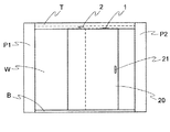
従来、建物入口の開口部または部屋入口の開口部などにおいて引き戸が用いられている。図15aおよび15bは、かかる引き戸の一例を示しており、図15aおよび15bにおいて、P1およびP2は柱であり、柱P1および柱P2の上端部および下端部にはそれぞれ鴨居Tおよび敷居Bが架設されている。そして、鴨居T、敷居Bおよび柱P1、P2で形成される開口部には引き戸である戸板20が摺動自在に取り付けられている。なお、図15aおよび15bにおいて、Wは壁であり、21は戸板20に形成された引き手である。
Conventionally, sliding doors are used in the opening of a building entrance or the opening of a room entrance. FIGS. 15a and 15b show an example of such a sliding door. In FIGS. 15a and 15b, P1 and P2 are columns, and Kamoi T and sill B are installed at the upper and lower ends of the columns P1 and P2, respectively. Has been. And the
図15aは戸板20が閉じられた状態を示しており、図15bは戸板20を開けた状態を示している。
15a shows a state in which the
ところで、図15aおよび15bに示されるタイプの引き戸の場合、戸板20の幅T1は、通常、開口部の幅T2のほぼ半分に設定されている。このため、戸板20を開けきった状態(図15b参照)では、戸板20の側縁20aは柱P1に当接しており、この状態では、開口を大きくとることができ、人や物の移動がし易くなるという利点はあるが、一方において、戸板20の引き手21が壁Wと対向する位置までくるため、図15bにおいて、紙面表側から戸板20を閉める際には引き手21を持つことができるが、紙面裏面から戸板20を閉める際には引き手21が持ちにくいという問題がある。この問題は、図15aおよび15bに示される例において、開口部の左半分に戸板20を収納する戸袋を設けた場合にとくに顕著になり、戸袋内に戸板20を完全に収納してしまうと、戸板20を引き出すのが非常に厄介である。
By the way, in the case of the type of sliding door shown in FIGS. 15a and 15b, the width T1 of the
本発明はかかる問題を解消するためになされたものであり、簡単な構成により、戸板を所定の位置に保持することができる保持金具および戸当り金具を提供することを目的とする。 The present invention has been made to solve such a problem, and an object of the present invention is to provide a holding metal fitting and a door fitting that can hold a door plate in a predetermined position with a simple configuration.
本発明の保持金具は、開口部に摺動自在に取り付けられた戸板を所定の位置に保持するための保持金具であって、
前記保持金具が、前記開口部を構成する枠部材に設けられる突出部および前記戸板に設けられる受け部からなり、
前記突出部が、ケースと、該ケースから出没できるように当該ケースに揺動自在に取り付けられた磁性体からなる可動舌片とからなり、
前記受け部が、前記突出部の可動舌片と対向する面に当該可動舌片の先端と係合する凹部が形成されたケースと、当該ケース内部に収納された磁石と、前記凹部内部に配設され、当該凹部内部に挿入される前記可動舌片の先端部を一時的に係止するための係止フックと、該係止フックに前記可動舌片を一時的に係止できる程度の係止力を付勢する付勢手段とからなり、
前記可動舌片が、該可動舌片の先端部に当該可動舌片の長手方向とほぼ垂直方向に延びる係合部が突設されてなることを特徴としている。
Holding metal fitting of the present invention is a holding metal fitting for holding the door leaf which is slidably mounted in the openings at predetermined positions,
The holding fixture is made is that accepted part provided in the projecting portion and the door leaf provided in a frame member constituting the opening,
The projecting portion comprises a case and a movable tongue piece made of a magnetic material swingably attached to the case so as to be able to appear and disappear from the case,
The receiving portion is disposed on the surface of the projecting portion facing the movable tongue piece, with a recess formed to engage the distal end of the movable tongue piece, a magnet housed in the case, and the recess. A locking hook for temporarily locking the distal end portion of the movable tongue piece inserted into the concave portion, and a degree of engagement for temporarily locking the movable tongue piece to the locking hook. Ri Do from a biasing means for biasing the locking force,
It said movable tongue, engaging portion extending substantially perpendicular to the longitudinal direction of the movable tongue is characterized Rukoto such is projected to the distal end portion of the movable Doshitahen.
前記可動舌片の先端部が、部分的に折り返されてなるのが好ましい。 It is preferable that the tip of the movable tongue piece is partially folded.
前記磁性体からなる可動部材の先端部に柔軟性を有する緩衝材が固着されてなるのが好ましい。 It is preferable that a flexible cushioning material is fixed to the tip of the movable member made of the magnetic material.
また、本発明の戸当りは、開口部に摺動自在に取り付けられた戸板を所定の位置を越えて移動できないように規制するための戸当り金具であって、前記戸当り金具が、前記開口部を構成する枠部材に設けられる突出部および前記戸板に設けられる受け部からなり、
前記突出部が、ケースと、該ケースから出没できるように当該ケースに揺動自在に取り付けられた磁性体からなる可動舌片とからなり、
前記受け部が、前記突出部の可動舌片と対向する面に当該可動舌片の先端と係合する凹部が形成されたケースと、当該ケース内部に収納された磁石と、前記凹部内部に配設され、当該凹部内部に挿入される前記可動舌片の先端部に突き当たる戸当り部材とからなり、
前記可動舌片が、該可動舌片の先端部に当該可動舌片の長手方向とほぼ垂直方向に延びる係合部が突設されてなることを特徴とする。
Further, doorstop of the present invention is a doorstop fittings for regulating the door leaf which is slidably mounted in the opening so that it can not move beyond the predetermined position, the doorstop fitting, the opening projecting portion provided on the frame member constituting a part and consists is that accepted part provided on the door leaf,
The projecting portion comprises a case and a movable tongue piece made of a magnetic material swingably attached to the case so as to be able to appear and disappear from the case,
The receiving portion is disposed on the surface of the projecting portion facing the movable tongue piece, with a recess formed to engage the distal end of the movable tongue piece, a magnet housed in the case, and the recess. is set, Ri Do and a doorstop member abuts on the tip portion of the movable tongue which is inserted inside the concave portion,
The movable tongue piece is characterized in that an engaging portion extending in a direction substantially perpendicular to the longitudinal direction of the movable tongue piece projects from the distal end portion of the movable tongue piece .
本発明によれば、突出部の可動舌片の先端部を受け部の係止フックに係止させることができ、それにより戸板を所定の位置に保持することができ、戸板の開閉操作をスムーズに行なうことができる。 According to the present invention, the distal end portion of the movable tongue piece of the protruding portion can be locked to the locking hook of the receiving portion, whereby the door plate can be held at a predetermined position, and the door plate can be opened and closed smoothly. Can be done.
また、可動部材の先端部に柔軟性を有する緩衝材を固着すれば、突出部と受け部とが連結するときなどの騒音の発生を抑えることができ、夜間における戸の開閉を静かに行なうことができる。 In addition, if a flexible cushioning material is fixed to the tip of the movable member, it is possible to suppress the generation of noise such as when the projecting part and the receiving part are connected, and quietly open and close the door at night. Can do.
つぎに図面を参照しながら本発明の保持金具を詳細に説明する。 Next, the holding metal fitting of the present invention will be described in detail with reference to the drawings.
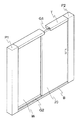
図1は本発明の保持金具が適用される引き戸の一例を示しており、2本の柱P1、P2によって囲まれ、壁Wを有する戸口において、柱P1、P2のあいだの開口部の上下両端において鴨居Tおよび敷居Bが設けられ、敷居B上を戸板20が摺動自在に取り付けられている。戸板20の上端は鴨居Tに形成された溝G1に、また戸板20の下端に形成された突条は、敷居Bに形成された溝G2に摺動自在に差し込まれている。また、戸板20が敷居B上を滑らかに摺動し得るように、戸板20の下端面に戸車を設けるようにしてもよい。
FIG. 1 shows an example of a sliding door to which the holding metal fitting of the present invention is applied. In a doorway surrounded by two pillars P1 and P2 and having a wall W, upper and lower ends of an opening between the pillars P1 and P2 , The duck T and the sill B are provided, and the
本発明の保持金具は、突出部1および受け部2とからなっており、本実施の形態においては、突出部1が戸板20の上端面に、受け部2が、開口部を構成する枠部材である鴨居Tの溝G1の底面に取り付けられている。突出部1および受け部2は、前記戸板20の上端面または溝G1の底面に直接取り付けるようにしてもよいし、当該上端面または底面に座ぐり加工などにより凹所を形成し、この凹所内に突出部1および受け部2をはめ込むようにしてもよい。
The holding metal fitting of the present invention includes a projecting
実施の形態1
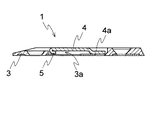
図4〜5に示される突出部1は、ケース3と、該ケース3から出没できるように当該ケース3に揺動自在に取り付けられた鉄などの磁性体からなる可動舌片4とから構成されている。突出部1は、図5に示されるように、全体の厚さが薄くなるように作製されているので、図3に示されるように、突出部1を戸板表面に大きく突出させずに取り付けることができる。
4 to 5 includes a
可動舌片4は、鉄などの磁性材料で作製された金属薄板からなる。可動舌片4の先端部5は、部分的に折り返されることにより裏側に突出しているため、後述する係止フック10に確実に係止され得る。なお、可動舌片4の先端部5を折り返す代わりに、可動舌片4の先端部5に係止フック10の爪部10aと係合される係合孔または係合凹部を形成したり、または可動舌片4の先端部の裏側に別体の係止ブロックを固着してもよい。たとえば、別体の係止ブロックとして、柔軟性を有する緩衝部材を可動舌片4の先端部5の裏側に固着させれば、可動舌片4がケース3内側に戻るときに騒音が発生しない。
The
また、図示されていないが、磁性体からなる可動舌片4の先端部5の全体に、合成樹脂などでモールド成形することにより柔軟性を有する緩衝部材を固着すれば、可動舌片4が受け部2の磁石9に吸引されて当該受け部2の凹部7に係合するとき、可動舌片4がケース3内部に戻るとき、および可動舌片4の先端部5が係止フック10に係止するときなどにおける騒音の発生を防止することができる。
Although not shown, if a flexible cushioning member is fixed to the entire
また、可動舌片4の部分4aの幅X1は、ケース3の開口3aの幅X2より広くなるように設定されているため、可動舌片4は開口3aから脱落することがない。
Further, since the width X1 of the
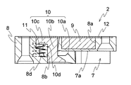
また、受け部2は、図6〜7に示されるように、前記突出部1の可動舌片4と対向する面に当該可動舌片4の先端部5と係合する凹部7が形成されたケース8と、当該ケース8内部に収納された磁石9と、前記凹部7内部に配設され、当該凹部7内部に挿入される前記可動舌片4の先端部5を一時的に係止するための係止フック10と、該係止フック10に前記可動舌片4を一時的に係止できる程度の係止力を付勢する付勢手段である圧縮コイルバネ11とから構成されている。
As shown in FIGS. 6 to 7, the
磁石9はケース8の底面に形成された2個の挿入穴8aに挿入され、裏蓋12によって封止されている。または、磁石9を内蔵した状態でケース8を合成樹脂などによって一体成形してもよい。
The
凹部7の内面のうちの一方の側には、当該凹部7の内奥面7aから当該凹部7の開口縁7bへ延びる斜面13が形成されている。斜面13の角度は、本発明においてはとくに限定されるものではないが、可動舌片4が開口縁7bに引っ掛からない程度の角度、通常45°未満程度、たとえば10〜40°程度に規定されるのが好ましい。
On one side of the inner surface of the
凹部7の内面のうちの他方の側には、係止フック10が、ケース8の厚さ方向(図7において、上下方向)に往復移動できるように配設されている。
A locking
具体的には、図7に示される係止フック10は、可動舌片4の先端部5に係止する爪部10aと、当該爪部10aと結合され、凹部7の内奥面7aに対してほぼ直角方向に延び、前記可動舌片4の先端部5に当接する当接部10bと、該当接部10bと結合され、裏蓋12と平行に延び、前記圧縮コイルバネ11を受ける受け座10cとから構成されている。圧縮コイルバネ11は、ケース8の取付穴8bに収容され、受け座10cの凹部10dと取付け穴8bの内奥面8cとのあいだで圧縮されている。また、内奥面8cには、半球状の突起8dが突設されているため、圧縮コイルバネ11の一端を係止することができる。
Specifically, the locking
本実施の形態の係止フック10は、圧縮コイルバネ11とともにケース8の裏側から挿入され、ついで、係止フック10の当接部10bに当接するように、スペーサ14を裏側から挿入することにより、係止フック10を往復移動自在に位置決めすることができる。
The locking
突出部1と受け部2とが近接した位置にあるときには、前記受け部2の磁石9の磁力により突出部1の可動舌片4が揺動して斜方に突出し、当該可動舌片4の先端部5が斜面13に沿って移動したのち前記凹部7内部の係止フック10に一時的に係止され、それにより戸板20を所定の位置に保持することができる。
When the protruding
図3に示されるように、可動舌片4の先端部5が係止フック10に係止されたとき、突出部1のケース3と受け部2のケース8とがほぼ当接する。また、このとき、受け部2の係止フック10は、若干もち上がるが、突出部1のケース3の開口3a(図5参照)内部に入るため、係止フック10の往復移動を支障なく行なうことができる。
As shown in FIG. 3, when the
また、突出部1と受け部2とが離れるときには、まず、可動舌片4の先端部5が係止フック10から離脱し、ついで、突出部1と受け部2とが離れるにつれて、可動舌片4は、前記磁石9の磁力の作用を受けなくなる。このとき、突出部1に対向する受け部2のケース8が可動舌片4を突出部1のケース3内部へ押し戻すことによって、突出部1と受け部2との係合が円滑に解除される。
Further, when the protruding
前述した突出部1および受け部2からなる保持金具を取り付けた引き戸は、図2aに示されるように戸板20を開け始めると、やがて突出部1と受け部2とが近接し、受け部2に内蔵された磁石の9の力により突出部1の可動舌片4が立ち上がり、その先端部5が受け部2の斜面13上を当接しつつ摺動し、係止フック10の当接部10bと当接して停止する。このとき圧縮コイルパネル11の付勢力によって可動舌片4は係止フック10に一時的に係止される(図2b参照)。その結果、戸板20を所定の位置に保持することができる。
As shown in FIG. 2A, the sliding door to which the holding metal fitting composed of the protruding
なお、突出部1および受け部2は、本実施の形態ではネジ止めにより戸板20の上端面および鴨居Tの溝G1の底面にそれぞれ固定されているが、接着剤など他の手段により固定することもできる。
In addition, although the
また、本実施の形態においては、突出部1を戸板20の上端面に設けているが、たとえば戸板として吊下げ式引き戸を採用するときは、敷居Bの溝G2の底面に設けることもできる。この場合、受け部2は戸板20の下端面に設けられる。
Moreover, in this Embodiment, although the
実施の形態2
図8〜12に、本発明の別の形態の保持金具を示す。本実施の形態2は、可動舌片の先端部両側に係合部が突設される保持金具である。
8 to 12 show another embodiment of the holding metal fitting of the present invention. The second embodiment is a holding metal fitting in which engaging portions protrude from both sides of the distal end portion of the movable tongue piece.
図8〜9に示される突出部1は、実施の形態1における突出部1に比較して、可動舌片4の先端部に当該可動舌片の長手方向とほぼ垂直方向に延びる係合部6が可動舌片4の両側に突設されている。なお、図9の(a)は図8の(a)のL−L線従断面図であり、図9の(b)は図8の(b)のM−M線従断面図である。図8の(a)および図9の(a)は突出部1が取付面(戸板上部または敷居底面)に直付けするタイプを示す。図8の(b)および図9の(b)は、取付面に座ぐり加工などにより凹所を形成し、この凹所内に突出部1を埋め込んで取り付けるタイプである。
8 to 9 is an
図10および図11は、図8に示す突出部1に組み合わされる受け部2を示す。また、図10の受け部2の係止フック10の形状を図12に示す。図10〜12に示すように、可動舌片4の先端と係合する凹部7が形成されたケース8の凹部の両角部に、係止フック10の爪部10aが形成されている。また、両側に爪部10aが形成されているので、係止フック10が安定するように、圧縮コイルバネ11を2つ備えており、2つの圧縮コイルバネ11を保持するために、係止フック10に突起10eが2つ形成されている(図12)。
10 and 11 show the receiving
本実施の形態2では、受け部の凹部7に、開口縁7bへ延びる斜面13が形成されておらず、凹部7はケース8の側方に開口している。磁石9がケース8の底面に形成された挿入穴8aに挿入され、裏蓋12によって封止されていることは、実施の形態1と同様である。本実施の形態2では、磁石が1個の場合を示している。実施の形態1のスペーサ14に相当する部材は、ケース8のはめ込み穴の形状を工夫することによって、省略されている。
In the second embodiment, the
可動舌片4が係止フック10に係止される動作は、実施の形態1では可動舌片の先端部5が爪部10aに結合するが、本実施の形態2では、可動舌片4の両側に突設された係合部6が、係止フック10の両爪部10aに結合する。その他の動作は、実施の形態1と同様なので、説明を省略する。
In the first embodiment, the
本実施の形態2における突出部1は、吊下げ式引き戸の振止め装置と共用することができる。すなわち、可動舌片4の先端両側に突出した係合部6が、吊下げ式引き戸下端に設けられた、下方に開口するほぼC字形状の断面を有するレール22に係合し、吊下げ式引き戸が振れるのを防止する(図14参照)。吊下げ式引き戸を保持したい位置に、レールに代わって本実施の形態2の受け部2を、レール22の断面と受け部2の凹部7が連続するように配置すれば、レール22端部から出た可動舌片4は、受け部2の磁石9に引き上げられたまま、係止フック10に係止される。このようにして、本実施の形態2の突出部1と受け部2を、吊下げ式引き戸の振止め装置および保持金具として使用することができる。
The
本実施の形態2では、突出部1が取付面(戸板上部または敷居底面)に直付けするタイプ(図8の(a))と、取付面に座ぐり加工などにより凹所を形成し、この凹所内に突出部1を埋め込んで取り付けるタイプ(図8の(b))とを示したが、埋め込みタイプの突出部1を敷居Bの溝G2の底面に埋め込み、また、受け部2を戸板20の下端面に埋め込むことによって、引き戸下端に保持金具を使用することができる。埋め込みタイプの突出部1は、上に受け部2がなく磁石9で可動舌片4が引き上げられなければ、敷居Bの溝G2の底面と同一面に収まるので、通行や引き戸の摺動に支障がない。
In the second embodiment, the
また、引き戸の上端面の隙間が小さい場合でも、埋め込みタイプによって、保持金具を使用することができる。 Even when the clearance between the upper end surfaces of the sliding door is small, the holding bracket can be used depending on the embedded type.
実施の形態3
実施の形態3では、戸当り金具として突出部および受け部を用いる場合を示す。引き戸を保持する必要はないが、ある位置を越えて動かせないように規制すればよい場合がある。たとえば、戸袋に収納する場合の最後の戸板が完全に収納されなければよいだけの場合や、引き戸を左右から閉める場合に中央をこえて反対に動かせないようにしたい場合などである。
In
図13は、突出部1および受け部を保持金具ではなく、引き戸をある位置を越えて動かせないように規制する戸当り金具として使用する場合の、戸当り部材15を示す。本実施の形態3において戸当り金具は、実施の形態2における突出部1と受け部2と同様に、突出部1および受け部2で構成される。
FIG. 13 shows the
図13の戸当り部材15は、実施の形態2における受け部2(図11)の係止フック10の代わりに、受け部2のケース8にはめ込まれる。実施の形態2と同様に、戸当り部材15を保持するために、圧縮コイルバネ11が2個使用される。
13 is fitted into the
突出部1としては、実施の形態2の突出部1(図8)を使用する。突出部1の可動舌片4の係合部6が、係止フック10に係止される代わりに、戸当り部材15に突き当たって、戸板が受け部2を越えて摺動することを規制する。
As the
戸当り部材には、爪部10aに代わって可動舌片4の係合部6を下から支えるように、緩衝部15aが形成されている。可動舌片4の係合部6はまず、この緩衝部15aに接触する。係合部6がさらに受け部の凹部7の奥側に動くと、緩衝部15aに形成された斜面を押して、戸当り部材を押し下げる。圧縮コイルバネ11と緩衝部15aの斜面の働きによって、戸板が戸当り部材に当る衝撃を緩和する。
A
本実施の形態3の突出部1を戸板20の上端面に設け、受け部2を鴨居Tの溝G1の底面に取り付けて、引き戸の戸当りとすることができる。
The protruding
本実施の形態3において、戸当り金具が吊下げ式引き戸に使用できることは、実施の形態2と同様である。すなわち、突出部1は吊下げ式引き戸の振止め防止装置と兼用でき、吊下げ式引き戸の下端に受け部を設置して、戸当りとすることができる。
In this
また、本実施の形態3の戸当り金具を、戸板の下端面に使用できることも、実施の形態2と同様である。
Moreover, it is the same as that of
1 突出部
2 受け部
4 可動舌片
5 先端部
6 係合部
9 磁石
10 係止フック
11 圧縮コイルバネ
15 戸当り部材
20 戸板
DESCRIPTION OF
Claims (6)
前記保持金具が、前記開口部を構成する枠部材に設けられる突出部および前記戸板に設けられる受け部からなり、
前記突出部が、ケースと、該ケースから出没できるように当該ケースに揺動自在に取り付けられた磁性体からなる可動舌片とからなり、
前記受け部が、前記突出部の可動舌片と対向する面に当該可動舌片の先端と係合する凹部が形成されたケースと、当該ケース内部に収納された磁石と、前記凹部内部に配設され、当該凹部内部に挿入される前記可動舌片の先端部を一時的に係止するための係止フックと、該係止フックに前記可動舌片を一時的に係止できる程度の係止力を付勢する付勢手段とからなり、
前記可動舌片の該先端部に、当該可動舌片の長手方向とほぼ垂直方向に延びる係合部が可動舌片の両側に突設されており、
前記係止フックに、当該係合部に係合する両爪部が形成されてなる保持金具。 A holding bracket for holding a door plate slidably attached to an opening in a predetermined position,
The holding metal fitting is composed of a protruding portion provided on a frame member constituting the opening and a receiving portion provided on the door plate,
The projecting portion comprises a case and a movable tongue piece made of a magnetic material swingably attached to the case so as to be able to appear and disappear from the case,
The receiving portion is disposed on the surface of the projecting portion facing the movable tongue piece, with a recess formed to engage the distal end of the movable tongue piece, a magnet housed in the case, and the recess. A locking hook for temporarily locking the distal end portion of the movable tongue piece inserted into the concave portion, and a degree of engagement for temporarily locking the movable tongue piece to the locking hook. Comprising a biasing means for biasing the stopping force,
Wherein the said distal end portion of the movable tongue, and engaging portions extending substantially perpendicular to the longitudinal direction of the movable tongue is protruded on both sides of the movable tongue,
A holding fitting in which both hooks engaging with the engaging portion are formed on the locking hook .
前記突出部が、ケースと、該ケースから出没できるように当該ケースに揺動自在に取り付けられた磁性体からなる可動舌片とからなり、
前記受け部が、前記突出部の可動舌片と対向する面に当該可動舌片の先端と係合する凹部が形成されたケースと、当該ケース内部に収納された磁石と、前記凹部内部に配設され、当該凹部内部に挿入される前記可動舌片の先端部に突き当たる戸当り部材とからなり、
前記可動舌片の該先端部に、当該可動舌片の長手方向とほぼ垂直方向に延びる係合部が可動舌片の両側に突設されており、
前記戸当り部材に、当該係合部に係合する両緩衝部が形成されてなる戸当り金具。 A door stop fitting for restricting a door plate slidably attached to an opening so as not to move beyond a predetermined position, and the door stop fitting is provided on a frame member constituting the opening. It consists of a protrusion and a receiving part provided on the door plate,
The projecting portion comprises a case and a movable tongue piece made of a magnetic material swingably attached to the case so as to be able to appear and disappear from the case,
The receiving portion is disposed on the surface of the projecting portion facing the movable tongue piece, with a recess formed to engage the distal end of the movable tongue piece, a magnet housed in the case, and the recess. A door stop member that abuts against the tip of the movable tongue inserted into the recess,
Wherein the said distal end portion of the movable tongue, and engaging portions extending substantially perpendicular to the longitudinal direction of the movable tongue is protruded on both sides of the movable tongue,
A door-holding metal fitting in which the buffer member is formed with both buffer portions that engage with the engaging portion .
Priority Applications (1)
| Application Number | Priority Date | Filing Date | Title |
|---|---|---|---|
| JP2004163564A JP4287789B2 (en) | 2004-01-13 | 2004-06-01 | Holding bracket and door-to-door bracket |
Applications Claiming Priority (2)
| Application Number | Priority Date | Filing Date | Title |
|---|---|---|---|
| JP2004005399 | 2004-01-13 | ||
| JP2004163564A JP4287789B2 (en) | 2004-01-13 | 2004-06-01 | Holding bracket and door-to-door bracket |
Publications (2)
| Publication Number | Publication Date |
|---|---|
| JP2005226442A JP2005226442A (en) | 2005-08-25 |
| JP4287789B2 true JP4287789B2 (en) | 2009-07-01 |
Family
ID=35001375
Family Applications (1)
| Application Number | Title | Priority Date | Filing Date |
|---|---|---|---|
| JP2004163564A Expired - Fee Related JP4287789B2 (en) | 2004-01-13 | 2004-06-01 | Holding bracket and door-to-door bracket |
Country Status (1)
| Country | Link |
|---|---|
| JP (1) | JP4287789B2 (en) |
Families Citing this family (4)
| Publication number | Priority date | Publication date | Assignee | Title |
|---|---|---|---|---|
| JP2009108649A (en) * | 2007-10-31 | 2009-05-21 | Tostem Corp | Door stopper |
| JP5811395B2 (en) * | 2011-07-29 | 2015-11-11 | Dic株式会社 | Double-sided drawer mechanism and double-sided drawer storage with the mechanism |
| JP5629728B2 (en) * | 2012-06-13 | 2014-11-26 | 株式会社陽洋 | Door to door |
| CN106150240B (en) * | 2016-08-26 | 2017-10-27 | 费一峰 | A kind of release device of |
-
2004
- 2004-06-01 JP JP2004163564A patent/JP4287789B2/en not_active Expired - Fee Related
Also Published As
| Publication number | Publication date |
|---|---|
| JP2005226442A (en) | 2005-08-25 |
Similar Documents
| Publication | Publication Date | Title |
|---|---|---|
| US7543409B2 (en) | Door pull and sash window having the door pull | |
| CN216788228U (en) | Air tightness keeping device for door and window hidden stile | |
| JP4287789B2 (en) | Holding bracket and door-to-door bracket | |
| JP2012092563A (en) | Airtight material and fitting | |
| US20240117668A1 (en) | Passive Door Bolt Assembly | |
| KR100550454B1 (en) | Sliding window with auto locking function | |
| JP3137474U (en) | Interlocking sliding door | |
| KR20190072202A (en) | Mounting structure of damping apparatus for window and window having the same | |
| JP4460747B2 (en) | Inner door shielding structure | |
| JP3533395B1 (en) | Closer with locking device | |
| JP4625122B2 (en) | Door to door | |
| JP3947516B2 (en) | Door to door | |
| US20050235568A1 (en) | Anti-rattle device for a pocket door assembly | |
| JP4009628B2 (en) | Sliding door closing support device | |
| JP7385893B2 (en) | Sliding door stopper device | |
| JP7395182B2 (en) | doorstop | |
| CN220184892U (en) | Magnetic attraction hook lock | |
| JP5016536B2 (en) | Door to door | |
| JPS5841330Y2 (en) | Sliding door locking device | |
| JP4408280B2 (en) | Orito | |
| JP2002188336A (en) | Fastener fitting | |
| JP3644171B2 (en) | Cushion support structure for sliding doors | |
| JP3104724U (en) | Sliding door stop structure | |
| JP6552897B2 (en) | Door to door | |
| JP5060754B2 (en) | Door device |
Legal Events
| Date | Code | Title | Description |
|---|---|---|---|
| A621 | Written request for application examination |
Free format text: JAPANESE INTERMEDIATE CODE: A621 Effective date: 20060110 |
|
| A977 | Report on retrieval |
Free format text: JAPANESE INTERMEDIATE CODE: A971007 Effective date: 20080117 |
|
| A131 | Notification of reasons for refusal |
Free format text: JAPANESE INTERMEDIATE CODE: A131 Effective date: 20080129 |
|
| A521 | Written amendment |
Free format text: JAPANESE INTERMEDIATE CODE: A523 Effective date: 20080326 |
|
| A131 | Notification of reasons for refusal |
Free format text: JAPANESE INTERMEDIATE CODE: A131 Effective date: 20081007 |
|
| A521 | Written amendment |
Free format text: JAPANESE INTERMEDIATE CODE: A523 Effective date: 20081014 |
|
| TRDD | Decision of grant or rejection written | ||
| A01 | Written decision to grant a patent or to grant a registration (utility model) |
Free format text: JAPANESE INTERMEDIATE CODE: A01 Effective date: 20090324 |
|
| A01 | Written decision to grant a patent or to grant a registration (utility model) |
Free format text: JAPANESE INTERMEDIATE CODE: A01 |
|
| A61 | First payment of annual fees (during grant procedure) |
Free format text: JAPANESE INTERMEDIATE CODE: A61 Effective date: 20090327 |
|
| FPAY | Renewal fee payment (event date is renewal date of database) |
Free format text: PAYMENT UNTIL: 20120403 Year of fee payment: 3 |
|
| R150 | Certificate of patent or registration of utility model |
Free format text: JAPANESE INTERMEDIATE CODE: R150 |
|
| FPAY | Renewal fee payment (event date is renewal date of database) |
Free format text: PAYMENT UNTIL: 20150403 Year of fee payment: 6 |
|
| R250 | Receipt of annual fees |
Free format text: JAPANESE INTERMEDIATE CODE: R250 |
|
| LAPS | Cancellation because of no payment of annual fees |