JP4286829B2 - Manufacturing method of rotating machine - Google Patents
Manufacturing method of rotating machine Download PDFInfo
- Publication number
- JP4286829B2 JP4286829B2 JP2005338118A JP2005338118A JP4286829B2 JP 4286829 B2 JP4286829 B2 JP 4286829B2 JP 2005338118 A JP2005338118 A JP 2005338118A JP 2005338118 A JP2005338118 A JP 2005338118A JP 4286829 B2 JP4286829 B2 JP 4286829B2
- Authority
- JP
- Japan
- Prior art keywords
- engagement
- core
- divided
- adjacent surface
- stator
- Prior art date
- Legal status (The legal status is an assumption and is not a legal conclusion. Google has not performed a legal analysis and makes no representation as to the accuracy of the status listed.)
- Active
Links
- 238000004519 manufacturing process Methods 0.000 title claims description 10
- 238000004804 winding Methods 0.000 claims description 37
- 229910000831 Steel Inorganic materials 0.000 claims description 7
- 239000010959 steel Substances 0.000 claims description 7
- 238000000034 method Methods 0.000 claims description 3
- 230000002093 peripheral effect Effects 0.000 description 8
- 238000010586 diagram Methods 0.000 description 5
- 239000012212 insulator Substances 0.000 description 4
- 230000007935 neutral effect Effects 0.000 description 3
- 238000009413 insulation Methods 0.000 description 2
- 238000005549 size reduction Methods 0.000 description 2
- RYGMFSIKBFXOCR-UHFFFAOYSA-N Copper Chemical compound [Cu] RYGMFSIKBFXOCR-UHFFFAOYSA-N 0.000 description 1
- 230000000694 effects Effects 0.000 description 1
- 230000004907 flux Effects 0.000 description 1
- 230000000414 obstructive effect Effects 0.000 description 1
- 239000002245 particle Substances 0.000 description 1
- 230000001105 regulatory effect Effects 0.000 description 1
- 230000011218 segmentation Effects 0.000 description 1
- 238000003892 spreading Methods 0.000 description 1
- 230000006641 stabilisation Effects 0.000 description 1
- 238000011105 stabilization Methods 0.000 description 1
- 230000001629 suppression Effects 0.000 description 1
- 238000003466 welding Methods 0.000 description 1
Images


Description
本発明は、磁石が円環状に配設されてなる外側回転子と、該外側回転子の内側に配設され、各々に巻線が巻回された複数の極部が外側へ放射線状に突設されてなる内側固定子とを具備する回転機の製造方法に関する。 The present invention provides an outer rotor in which magnets are arranged in an annular shape, and a plurality of pole portions, which are arranged inside the outer rotor and each have a winding wound around, project radially outward. The present invention relates to a method of manufacturing a rotating machine including an inner stator.
また、本発明は、磁石が円環状に配設されてなる固定子と、該固定子の内側に配設され、各々に巻線が巻回された複数の極部が外側へ放射線状に突設されてなる回転子とを具備する回転機の製造方法に関する。 In addition, the present invention provides a stator in which magnets are arranged in an annular shape, and a plurality of pole portions that are arranged inside the stator and each have windings wound radially outward. The present invention relates to a method of manufacturing a rotating machine including a rotor that is provided.
従来より、円環状の外側固定子の内側に回転子が配設された回転機として、例えば、図5に示すような、インナーロータ型のモータ90が知られている。該インナーロータ型のモータ90の外側固定子は、ステータコアをティース部毎に分割した分割コア91を円環状に組み合わせて、レーザ溶接等により締結されており、円環状に組み合わされた分割コア91の外周側には筒状部材92が配設されている。該筒状部材92により外周面の位置が規制された各分割コア91は、隣接する分割コア91のヨーク部同士が密接した状態で円環状に維持されている(例えば特許文献1参照)。
Conventionally, for example, an inner
一方、円環状の外側回転子の内側に、内側固定子が配設されてなる回転機として、例えば、アウターロータ型のモータが知られているが、アウターロータ型のモータの内側固定子をティース部毎に分割した分割コアとして円環状に締結することは困難である。アウターロータ型のモータの内側固定子は、ティース部が外側へ向かって放射線状に突出しており、該ティース部に対して所定の磁気ギャップを隔てて円環状の外側回転子が配設されるので、内側固定子の外周に上記筒状部材92のような部材を嵌め込むことはできない。また、内側固定子の中空部にはモータの軸等が圧入される。これにより、内側固定子に対して径方向外側の応力が加わるので、内側固定子を分割すれば、分割コアが径方向外側へ容易に広がってしまうという問題がある。
On the other hand, for example, an outer rotor type motor is known as a rotating machine in which an inner stator is disposed inside an annular outer rotor. It is difficult to fasten in an annular shape as a divided core divided into parts. The inner stator of the outer rotor type motor has a tooth portion protruding radially outward, and an annular outer rotor is disposed with a predetermined magnetic gap with respect to the tooth portion. A member such as the
したがって、アウターロータ型のモータの内側固定子は、円環状のステータコアを一体として形成さざるを得ないが、例えば、電磁鋼板を円環状のステータコアの形状に打ち抜き積層する場合に、円環状のステータコアを一体に打ち抜くと歩留まりが低くなるという問題がある。また、一体のステータコアのティース部には、巻線作業時に隣り合うティース部が邪魔となって、集中巻線がし難いという問題がある。したがって、ティース部への巻線は主として分布巻きになるが、その結果、巻線の占積率が低くなってモータ性能の向上が困難となったり、分布巻きの重なり部分がステータコアの軸方向に膨らんで、モータの小型化が困難になるという問題が生じる。 Accordingly, the inner stator of the outer rotor type motor must be formed integrally with an annular stator core. For example, when an electromagnetic steel sheet is punched and laminated into an annular stator core shape, There is a problem that the yield is lowered when punched out together. In addition, the teeth portion of the integral stator core has a problem that adjacent winding portions are obstructive during winding work, and concentrated winding is difficult. Therefore, although the winding to the teeth portion is mainly distributed winding, as a result, the space factor of the winding becomes low and it becomes difficult to improve the motor performance, or the overlapping portion of the distributed winding is in the axial direction of the stator core. A problem arises in that it becomes difficult to reduce the size of the motor.
また、円環状の固定子の内側に、回転子が配設されてなる回転機として、例えば、ブラシ付き直流モータが知られている。ブラシ付き直流モータの回転子においても、前述のアウターロータ型のモータと同様に、ティース部毎に分割された分割コアを円環状に締結することは困難である。したがって、前述と同様に、ティース部への巻線を分布巻きにすれば、巻線の占積率が低くなってモータ性能の向上が困難となったり、分布巻きの重なり部分がステータコアの軸方向に膨らんで、モータの小型化が困難になるという問題が生じる。 As a rotating machine in which a rotor is disposed inside an annular stator, for example, a brushed DC motor is known. Also in the rotor of a brushed DC motor, it is difficult to fasten the divided cores divided for each tooth portion in an annular shape, as in the above-described outer rotor type motor. Therefore, as described above, if the winding to the teeth portion is distributed winding, the space factor of the winding becomes low and it becomes difficult to improve the motor performance, or the overlapping portion of the distributed winding is in the axial direction of the stator core. This causes a problem that it is difficult to reduce the size of the motor.
本発明は、かかる問題に鑑みてなされたものであり、磁石が円環状に配設されてなる外側回転子と、該外側回転子の内側に配設され、各々に巻線が巻回された複数の極部が外側へ放射線状に突設されてなる内側固定子とを具備する回転機において、内側固定子が外力を受けて径方向外側へ広がることなく、所定の極部毎に内側固定子を分割可能とする手段を提供することを目的とする。 The present invention has been made in view of such a problem, and an outer rotor in which magnets are arranged in an annular shape, and an inner side of the outer rotor, each of which is wound with a winding. In a rotating machine having an inner stator in which a plurality of poles project radially outwardly, the inner stator receives an external force and does not spread outward in the radial direction. It is an object of the present invention to provide a means for dividing a child.
また、本発明の他の目的は、磁石が円環状に配設されてなる固定子と、該固定子の内側に配設され、各々に巻線が巻回された複数の極部が外側へ放射線状に突設されてなる回転子とを具備する回転機において、回転子が外力を受けて径方向外側へ広がることなく、所定の極部毎に回転子を分割可能とする手段を提供することを目的とする。 Another object of the present invention is to provide a stator in which magnets are arranged in an annular shape, and a plurality of pole portions that are arranged inside the stator and each have a winding wound around. In a rotating machine comprising a rotor projecting radially, a means is provided that allows the rotor to be divided into predetermined pole parts without the rotor receiving an external force and spreading outward in the radial direction. For the purpose.
本発明は、磁石が円環状に配設されてなる外側回転子と、該外側回転子の内側に配設され、各々に巻線が巻回された複数の極部が外側へ放射線状に突設されてなる内側固定子と、を具備する回転機の製造方法であって、所定の極部毎に分割されており、巻線が巻回される極部と他の分割固定子と連結されるコアヨーク部とをそれぞれ有する同一形状の複数の鋼板が積層されて一体に嵌合され、当該コアヨーク部において隣り合うコアヨーク部と隣接する隣接面に、当該隣接面から円環状の配列における周方向へ凹み、当該隣接面に沿った開口部より奥部側が幅広のあり溝である係合凹部、又は、当該隣接面から円環状の配列における周方向へ凸であり、当該隣接面に沿った基部より先端部側が幅広であって上記あり溝と係合し得る係合凸部のいずれか一方が形成された複数の分割固定子を、上記係合凹部と上記係合凸部とを隙間嵌めにして相互に係合して円環状に配列し、上記円環状に配列された分割固定子の内側に円柱形状の芯部材を圧入することによって、上記複数の分割固定子における係合凹部と係合凸部との係合を強固にして、上記内側固定子とするものである。 The present invention provides an outer rotor in which magnets are arranged in an annular shape, and a plurality of pole portions, which are arranged inside the outer rotor and each have a winding wound around, project radially outward. A rotating machine comprising an inner stator, and divided into predetermined pole parts, and connected to a pole part around which a winding is wound and another divided stator. A plurality of steel plates of the same shape each having a core yoke portion are stacked and integrally fitted, and the adjacent surface adjacent to the adjacent core yoke portion in the core yoke portion extends from the adjacent surface to the circumferential direction in an annular arrangement. From the concave part, the engagement concave part that is wider and wider than the opening along the adjacent surface, or the convex part in the circumferential direction in the annular arrangement from the adjacent surface, from the base part along the adjacent surface The engagement convex part is wide at the tip side and can engage with the dovetail groove. A plurality of split stator deviation or the other have been formed, arranged annularly engaged with each other by the clearance fit between the engagement recesses and the engagement projection, which is arranged in the annular split By press-fitting a cylindrical core member inside the stator, the engagement between the engagement concave portions and the engagement convex portions in the plurality of split stators is strengthened to form the inner stator.
ここで、開口部とは、隣接面から周方向へ形成された係合凹部が隣接面に開口した部分をいい、奥部とは、該係合凹部が凹んでいる奥側の部分をいう。また、基部とは、隣接面から周方向へ形成された係合凸部の隣接面に沿った基の部分をいい、先端部とは、該係合凸部が突出する先端の部分をいう。 Here, the opening portion refers to a portion where an engagement concave portion formed in the circumferential direction from the adjacent surface opens to the adjacent surface, and the back portion refers to a portion on the back side where the engagement concave portion is recessed. The base portion refers to the base portion along the adjacent surface of the engaging convex portion formed in the circumferential direction from the adjacent surface, and the tip portion refers to the tip portion from which the engaging convex portion protrudes.
また、上記分割固定子を円環状に配列する前に、磁気回路を形成する各相毎に、所定の複数の分割固定子の極部に巻線を並列巻きしてもよい。 Further, before arranging the split stators in an annular shape, a winding may be wound in parallel around the pole portions of a predetermined plurality of split stators for each phase forming the magnetic circuit.
また、本発明は、磁石が円環状に配設されてなる固定子と、該固定子の内側に配設され、各々に巻線が巻回された複数の極部が外側へ放射線状に突設されてなる回転子とを具備する回転機の製造方法であって、所定の極部毎に分割されており、巻線が巻回される極部と他の分割コアと連結されるコアヨーク部とをそれぞれ有する同一形状の複数の鋼板が積層されて一体に嵌合され、当該コアヨーク部において隣り合うコアヨーク部と隣接する隣接面に、当該隣接面から円環状の配列における周方向へ凹み、当該隣接面に沿った開口部より奥部側が幅広のあり溝である係合凹部、又は、当該隣接面から円環状の配列における周方向へ凸であり、当該隣接面に沿った基部より先端部側が幅広であって上記あり溝と係合し得る係合凸部のいずれか一方が形成された複数の分割コアを、上記係合凹部と上記係合凸部とを隙間嵌めにして相互に係合して円環状に配列し、上記円環状に配列された分割コアの内側に円柱形状の芯部材を圧入することによって、上記複数の分割固定子における係合凹部と係合凸部との係合を強固にして、上記回転子とするものである。 In addition, the present invention provides a stator in which magnets are arranged in an annular shape, and a plurality of pole portions that are arranged inside the stator and each have windings wound radially outward. A rotor manufacturing method comprising: a rotor provided; and a core yoke portion that is divided for each predetermined pole portion and is connected to a pole portion around which a winding is wound and another divided core A plurality of steel plates of the same shape having each of the above are laminated and integrally fitted, and in the adjacent surface adjacent to the adjacent core yoke portion in the core yoke portion, are recessed in the circumferential direction from the adjacent surface in an annular arrangement , An engagement recess that is a dove groove that is wider on the back side than the opening along the adjacent surface, or is convex in the circumferential direction in the annular array from the adjacent surface, and the distal end side is closer to the base side along the adjacent surface Any one of the engaging projections that are wide and can engage with the dovetail groove A plurality of divided cores but formed, the clearance fit between the engaging recess and the engaging protrusion arranged annularly engaged with each other, the inside of the divided cores are arranged in the annular By press-fitting a cylindrical core member, the engagement between the engagement concave portions and the engagement convex portions in the plurality of divided stators is strengthened, and the rotor is formed.
ここで、開口部とは、隣接面から周方向へ形成された係合凹部が隣接面に開口した部分をいい、奥部とは、該係合凹部が凹んでいる奥側の部分をいう。また、基部とは、隣接面から周方向へ形成された係合凸部の隣接面に沿った基の部分をいい、先端部とは、該係合凸部が突出する先端の部分をいう。 Here, the opening portion refers to a portion where an engagement concave portion formed in the circumferential direction from the adjacent surface opens to the adjacent surface, and the back portion refers to a portion on the back side where the engagement concave portion is recessed. The base portion refers to the base portion along the adjacent surface of the engaging convex portion formed in the circumferential direction from the adjacent surface, and the tip portion refers to the tip portion from which the engaging convex portion protrudes.
また、上記分割コアを円環状に配列する前に、磁気回路を形成する各相毎に、所定の複数の分割コアの極部に巻線を並列巻きしてもよい。 Further, before arranging the divided cores in an annular shape, a winding may be wound in parallel around the poles of a predetermined plurality of divided cores for each phase forming the magnetic circuit.
本発明によれば、所定の極部毎に分割された分割固定子が、少なくとも周方向の密接状態を維持するように係合されて隣接するので、該分割固定子の円環状に配列が維持される。したがって、分割固定子が径方向外側へ容易に広がってしまうことがない。これにより、分割固定子の極部への集中巻線が可能となり、回転機の性能の向上及び小型化を図ることができる。 According to the present invention, since the divided stators divided for each predetermined pole part are engaged and adjacent to each other so as to maintain at least a circumferential close state, the arrangement of the divided stators is maintained in an annular shape. Is done. Therefore, the split stator does not easily spread outward in the radial direction. Thereby, the concentrated winding to the pole part of a split stator is attained, and the performance and size reduction of a rotary machine can be achieved.
また、本発明によれば、所定の極部毎に分割された分割コアが、少なくとも周方向の密接状態を維持するように係合されて隣接するので、該分割コアの円環状に配列が維持される。したがって、分割コアが径方向外側へ容易に広がってしまうことがない。これにより、分割コアの極部への集中巻線が可能となり、回転機の性能の向上及び小型化を図ることができる。 Further, according to the present invention, the divided cores divided for each predetermined pole part are engaged and adjacent to each other so as to maintain at least a close contact state in the circumferential direction, so that the arrangement of the divided cores is maintained in an annular shape. Is done. Therefore, the split core does not easily spread outward in the radial direction. Thereby, the concentrated winding to the pole part of a division | segmentation core is attained, and the improvement and size reduction of a rotary machine can be achieved.
以下、本発明の好ましい実施形態について、適宜図面を参照しながら説明する。なお、本実施の形態においては、本発明に係る回転機を電動機として説明するが、本発明に係る回転機を同様の構成で発電機としても実施できる。 Hereinafter, preferred embodiments of the present invention will be described with reference to the drawings as appropriate. In the present embodiment, the rotating machine according to the present invention will be described as an electric motor. However, the rotating machine according to the present invention can also be implemented as a generator with the same configuration.
図1は、本発明の実施の形態に係るブラシレスモータ1(回転機,電動機)の構成を示すものである。該ブラシレスモータ1は、内側固定子2と外側回転子3とから構成されるアウターロータ型のものであり、内側固定子2の外周側に所定の磁気ギャップを隔てて外側回転子3が配設され、内側固定子2により形成される回転磁界により外側回転子3が回転するように構成されている。
FIG. 1 shows a configuration of a brushless motor 1 (rotary machine, electric motor) according to an embodiment of the present invention. The
内側固定子2は、ブラシレスモータ1の軸となるシャフト20(芯部材)と、コイル21(巻線)が巻回された18個の分割コア22(分割固定子)が円環状に連結されたステータコア23とからなる。一方、外側回転子3は、上記シャフト20を軸として回転するリング部材30と、該リング部材30の内周面に固定された20極の磁石31とからなる。磁石31は、磁石粒子が焼結された永久磁石であり、周方向にN極とS極とが交互となって20極の磁極が形成されている。
The
なお、磁石31は、円筒状に焼結された所謂リングマグネットや各磁極で分割されたもの等、周知のモータ用磁石を用いることができる。また、図には示していないが、上記内側固定子2と外側回転子3とはブラシレスモータ1のフレーム内に収容されている。また、なお、本実施の形態では、20極・18スロットのブラシレスモータ1を例に説明しているが、本発明において回転機の極数及びスロット数は特に限定されるものではない。
The
上記内側固定子2を構成する18個の各分割コア22は、円環状に連結される配置が異なる他は同形状のものであり、各分割コア22が連結されて1つの円環状のステータコア23を構成している。なお、本実施の形態では、分割コア22はステータコア23をティース部24毎に分割されたものとしたが、本発明において分割コア22は必ずしもティース部24毎に分割されたものである必要はなく、ステータコア23が複数に分割されていれば、例えば、所定の幾つかのティース部24毎にステータコア23を分割したものであってもよい。
The 18 divided
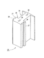
図2に示すように、分割コア22は、コイル21が巻回されるティース部24が、他の分割コア22と円環状に連結されるコアヨーク部25から突出したものであり、平面視において同一形状の複数の鋼板が積層され、半抜きされたカシメ部26が上下方向の鋼板と嵌合することにより一体とされている。コアヨーク部25は、円環状のステータコア23の周方向の幅の18分の1となる弧状に形成されている。ティース部24は、該コアヨーク部25からステータコア23の径方向外側へ突出しており、絶縁のためのインシュレータ等を介してコイル21が巻回される。
As shown in FIG. 2, the
コイル21の巻回は、各分割コア22が独立した状態でなされる。これにより、各分割コア22のティース部24周りに巻線作業のための空間を確保することができるので、ティース24にコイル21を密に巻回することができる。コイル21の巻回方法は特に限定されるものではないが、フライヤ式又はノズル式の巻線機を用いて複数の分割コア22に対して1本の銅線を連続して巻回し、該複数の分割コア22をコイル21間の渡り線により連結させて1群のものとすれば、複数の分割コア22の1群を、例えばU相、V相、W相の各相に対応させて所定の配置で円環状に連結することができ、結線作業が簡略化されるので好適である。
The
図2及び図3に示すように、分割コア22のコアヨーク部25の隣接面27には係合凹部28及び係合凸部29がそれぞれ形成されている。隣接面27は、各分割コア22が、図1に示すような円環状のステータコア23として組み合わされる場合に、隣り合う分割コアのコアヨーク部25と接触する面であり、ステータコア23の径方向となるコアヨーク部25の両端において、ステータコア23の軸方向となる平面をなしている。また、係合凹部28及び係合凸部29は、該隣接面27の上下方向、換言すれば円環状のステータコア23の軸方向に沿ってそれぞれ形成されている。
As shown in FIGS. 2 and 3, an engagement
係合凹部28は、上記コアヨーク部25の隣接面27からステータコア23の周方向へ凹欠されたものである。図3に示すように、係合凹部28が隣接面27に開口する開口部28Aの径方向の幅W1に対して、係合凹部28の奥部28Bの径方向の幅W2が幅広となっており、開口部28Aから奥部28Bへは連続的に拡幅されるあり面28Cが形成されている。
The engaging
一方、係合凸部29は、上記コアヨーク部25の隣接面27からステータコア23の周方向へ突出されたものである。図に示すように、係合凸部29の隣接面27に沿った基部29Aの径方向の幅W1に対して、係合凸部29の先端部29Bの径方向の幅W2が幅広となっており、基部29Aから先端部29Bへは連続的に拡幅されるテーパ面29Cが形成されている。
On the other hand, the engaging
上記係合凹部28と係合凸部29とは、互いに対応した凹凸形状であり、係合凹部28及び係合凸部29は、隣接面27の径方向の略中央に形成されている。そして、図1に示すように、分割コア22がステータコア23として円環状に組み付けられた際には、係合凹部28及び係合凸部29が、それぞれ隣り合う他の分割コア22の係合凸部29又は係合凹部28と係合する。
The engaging
前述したように、係合凹部28の開口部28Aの径方向の幅W1と係合凸部29の基部29Aの径方向の幅W1とは同寸法であり、また、係合凹部28の奥部28Bの径方向の幅W2と係合凸部29の先端部29Bの径方向の幅W2とは同寸法である。さらに、係合凹部28のあり面28Cと係合凸部29のテーパ面29Cとは同一の傾斜角度となっている。したがって、係合凹部28と係合凸部29とが密嵌するようにして係合し、この係合状態において、あり面28Cとテーパ面29Cとが密接し、また、コアヨーク部25の隣接面27は、隣り合う他の分割コア22のコアヨーク部25の隣接面27と密接する。
As described above, the radial width W1 of the
なお、上記係合凹部28及び係合凸部29において、係合凹部28の開口部28Aの径方向の幅W1及び奥部28Bの径方向の幅W2の公差をプラス側に、係合凸部29の基部29Aの径方向の幅W1及び先端部29Bの径方向の幅W2の公差をマイナス側とすれば、係合凹部28と係合凸部29との係合作業が容易となるので好適である。このような公差は、分割コア22のコアヨーク部25の隣接面27の密接状態が、ブラシレスモータ1のモータ特性に影響を与えない範囲で設定すればよい。
It should be noted that in the
上記係合凹部28と係合凸部29との係合により、隣接する分割コア22は、ステータコア23の径方向及び周方向に対して互いのコアヨーク部25が固定される。すなわち、隣接する分割コア22のコアヨーク部25の各隣接面27が、その径方向の両端を合致させて密接し、その密接した隣接面27が離間することなく維持される。
Due to the engagement between the
そして、18個の分割コア22を、互いの係合凹部28と係合凸部29とを係合させて組み付けることにより、18個の分割コア22が隣接面27を密接させた状態で、コイル21が巻回されたティース部24を外側へ放射線状に突出させた円環状のステータコア23となり、その円環形状が係合凹部28と係合凸部29との係合により維持される。また、上記係合凹部28及び係合凸部29は、分割コア22の隣接面27の径方向略中央に形成されているので、係合凹部28と係合凸部29との係合により隣接する分割コア22に付与される周方向の密接力が、各分割コア22の隣接面27に対して平均して負荷される。
Then, the eighteen divided
そして、上記分割コア22が円環状に組み付けられたステータコア23の中空部にシャフト20が圧入される。これにより、各分割コア22の係合凹部28と係合凸部29との係合状態が一層強固になるとともに、該シャフト20が中芯となって内側固定子の剛性が高まる。また、シャフト20が圧入されることにより、円環状に組み付けられた分割コア22に対して径方向外側への応力が負荷されるが、係合凹部28と係合凸部29との係合により、分割コア22が周方向に離れるようにして径方向外側へ広がることがない。
Then, the
このように、本ブラシレスモータ1によれば、分割コア22が、係合凹部28と係合凸部29との係合により、ステータコア23の周方向に対して隣接面27の密接状態を維持して、円環状のステータコア23を形成することができる。
As described above, according to the
なお、本実施の形態では、分割コア22のコアヨーク部25には、係合凹部28と係合凸部29とが形成されるものとしたが、必ずしも係合凹部28及び係合凸部29の双方が形成される必要はなく、隣接する分割コア22の係合が可能であれば、これらの少なくともいずれか一方が形成されていればよい。したがって、例えば、係合凹部28のみが形成された分割コア22と、係合凸部29のみが形成された分割コア22とを、互い違いに配置してこれらを係合させ、円環状のステータコア23とすることもできる。
In the present embodiment, the
また、本発明に係る係合凹部及び係合凸部の形状は、分割コア22の隣接面27から周方向へ凹凸するように形成され、隣接面27に沿った開口部又は基部より奥部側又は先端部側が幅広のものであればよい。
In addition, the shape of the engagement recess and the engagement protrusion according to the present invention is formed so as to be uneven in the circumferential direction from the
例えば、図4に示すように、隣接面27に部分円形状の係合凹部40及び係合凸部41を形成することとしてもよい。なお、図において、上記実施の形態と同一の符号のものは同一の部材を示している。図に示すように、係合凹部40は、隣接面27に開口する開口部40Aの径方向の幅W3に対して幅広となる係合凹部28の円形状の直径W4が奥部40B側となる部分円形状に形成されている。一方、係合凸部41は、係合凸部41の隣接面27に沿った基部41Aの径方向の幅W3に対して幅広となる係合凸部41の円形状の直径W4が先端部41B側となる部分円形状に形成されている。そして、上記係合凹部40と係合凸部41の部分円形状は同一直径の円で合致している。
For example, as shown in FIG. 4, it is good also as forming the engagement recessed
したがって、分割コア22がステータコア23として円環状に組み付けられた際には、係合凹部40及び係合凸部41が、それぞれ隣り合う他の分割コア22の係合凸部40又は係合凹部41と係合することにより、隣接する分割コア22は、ステータコア23の径方向及び周方向に対して互いのコアヨーク部25が固定され、隣接する分割コア22のコアヨーク部25の各隣接面27が、その径方向の両端を合致させて密接し、その密接した隣接面27が離間することなく維持される。このような係合凹部40及び係合凸部41によっても、上記実施の形態と同様の効果を発揮させることができる。
Therefore, when the
以下、本発明の別の実施形態について説明する。図6は、本発明の別の実施形態に係るブラシレスモータ5(回転機,発電機)の構成を示すものである。ブラシレスモータ5は、内側固定子6と外側回転子7とから構成されるアウターロータ型のものであり、内側固定子6の外周に所定の磁気ギャップを隔てて外側回転子7が配設され、内側固定子6により形成される回転磁界により外側回転子7が回転するように構成されている。
Hereinafter, another embodiment of the present invention will be described. FIG. 6 shows a configuration of a brushless motor 5 (rotary machine, generator) according to another embodiment of the present invention. The
内側固定子6は、ブラシレスモータ5の軸となるシャフト50(芯部材)と、コイル51(巻線)が巻回された9個の分割コア52(分割固定子)が円環状に連結されたステータコア53とからなる。各分割コア52は、円環状に連結される配置が異なる他は同形状のものである。
The
外側回転子7は、リング部材60と、リング部材60の内周面に固定された48極の磁石61とからなる。磁石61は、永久磁石であり、周方向にN極とS極とが交互となって48極の磁極が形成されている。
The
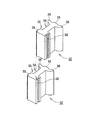
図7に示すように、分割コア52は、コイル51が巻回されるティース部54が、他の分割コア52と円環状に連結されるコアヨーク部55から径方向外側へ突出されたものである。コアヨーク部55は、円環状のステータコア53の方向の9分の1となる弧状に形成されている。
As shown in FIG. 7, the
ティース部54には、絶縁のためのインシュレータが被覆され、該インシュレータの上からコイル51が巻回される。コイル51の巻回は、各分割コア52が独立した状態でなされる。本実施形態では、各分割コア52のコイル51は並列巻線されるものであり、各分割コア52に、コイル51がそれぞれ巻回される。換言すれば、複数の分割コア52に対して1本の巻線が巻回されて、各分割コア52のコイル51間に渡り線が形成されるような連続巻きはされない。
The
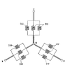
図8は、各分割コア52のコイル51の結線図である。9個の分割コア52のティース部54にそれぞれ巻回された各コイル51は、3個ずつでU相、V相、W相の3相の磁気回路を形成する。図8においては、U相を形成するコイルが51U、V相を形成するコイルが51V、W相を形成するコイルが51Wで示されている。U相を構成する3個のコイル51Uの各端部である各入出力線は、U相の外部接続端子Uと中性点Nとにそれぞれ並列結線される。換言すれば、3個のコイル51U間には渡り線はない。同様に、V相を構成する3個のコイル51Vの各端部である各入出力線は、V相の外部接続端子Vと中性点Nとにそれぞれ並列結線され、W相を構成する3個のコイル51Wの各端部である各入出力線は、W相の外部接続端子Wと中性点Nとにそれぞれ並列結線される。
FIG. 8 is a connection diagram of the
図7に示すように、ティース部54の外周面、すなわち外側回転子7の磁石61と対向する面に、ステータコア53の軸方向に延びる2つの凹溝が周方向に隔てて形成されることにより、ティース部54の磁石61と対向する部分が、3つの小歯56に分割されている。各小歯56のピッチは、磁石61の磁極ピッチに対応されており、具体的には磁石61の2極分と略同一である。この小歯56のピッチや開角(電気角)は、ブラシレスモータ5のコギングトルクの低下や、トルク変動の安定化による振動抑制を考慮して適宜設定される。
As shown in FIG. 7, two concave grooves extending in the axial direction of the stator core 53 are formed on the outer peripheral surface of the
また、ティース部54を小歯56に分割することにより、外側回転子7の磁石61が多極化される。これにより、隣接する磁石61間においてリング部材60の厚み方向を通過する磁束数が少なくなり、リング部材60の厚みを薄くしてブラシレスモータ5を小型化することができる。
Further, by dividing the
図7に示すように、分割コア52のコアヨーク部55の隣接面57には、係合凹部58及び係合凸部59がそれぞれ形成されている。隣接面57は、各分割コア52が、図6に示す円環状のステータコア53として組み合わされる場合に、隣り合う分割コア52のコアヨーク部55と接触する面であり、ステータコア53の径方向となるコアヨーク部55の両端において、ステータコア53の軸方向となる平面をなしている。係合凹部58及び係合凸部59は、隣接面57においてステータコア53の軸方向に沿ってそれぞれ形成されている。係合凹部58及び係合凸部59は、上記実施形態において説明した形状であるので、詳細な説明は省略する。
As shown in FIG. 7, an engagement
係合凹部58と係合凸部59との係合により、隣接する分割コア52は、ステータコア53の径方向及び周方向に対して互いのコアヨーク部55が固定される。9個の分割コア52を、互いの係合凹部58と係合凸部59とを係合させる際には、図7に示すように、隣接する2つの分割コア54を、ステータコア53の軸方向にずらせた状態として、一方の分割コア52の係合凹部58の上面側に、他方の分割コア52の係合凸部59の下面側を嵌入させ、その状態で、2つの分割コア52を軸方向に相対的に移動させて、各分割コア52の上下面を同一面とすることにより、係合が完了する。
Due to the engagement between the engagement
前述したように、各分割コア52のティース部54に巻回されたコイル51は並列巻線されているので、U相、V相、W相をそれぞれ形成するコイル51間に渡り線は存在しない。したがって、分割コア52の係合に際して、隣接する分割コア52をステータコア53の軸方向にずらせることが容易なので、ステータコア53の組み付けが容易である。そして、各分割コア52が円環状に組み付けられたステータコア53の中空部にシャフト50が圧入される。
As described above, since the
このように、本実施形態に係るブラシレスモータ5によれば、分割コア52が、係合凹部58と係合凸部59との係合により、ステータコア53の周方向に対して隣接面57の密接状態を維持して、円環状のステータコア53を形成することができる。
As described above, according to the
また、各分割コア52のコイル51が並列巻線されているので、分割コア52を係合してステータコア53とする組み付け作業が容易である。さらに、分割コア52のティース部54に小歯56を形成したので、ブラシレスモータ5のコギングトルクを低下し、且つトルク変動を抑制することができる。また、リング部材60の厚みを薄くして、ブラシレスモータ5の小型化を実現することができる。
In addition, since the
図9は、本発明の別の実施形態に係るブラシ付き直流モータ9(回転機,電動機)の概略構成を示すものである。ブラシ付き直流モータ9は、回転子10と固定子11とから構成され、回転子10の外周側に所定の磁気ギャップを隔てて固定子11が配設され、回転子10により形成される回転磁界によりシャフト20が回転するように構成されている。
FIG. 9 shows a schematic configuration of a brushed DC motor 9 (rotary machine, electric motor) according to another embodiment of the present invention. The brushed DC motor 9 includes a
回転子10は、ブラシ付き直流モータ9の軸となるシャフト20と、コイル21が巻回された18個の分割コア22が円環状に連結されたステータコア23とからなる。シャフト20には、整流子を構成する複数のセグメント70が、ステータコア23と同軸に円筒状に相互に絶縁して配置されて固定されている。一方、固定子11は、ブラシ付き直流モータ9の筐体を兼ねたヨークハウジング71のの内周面に固定された20極の磁石31とからなる。ヨークハウジング71は、回転子10のシャフト20をベアリングを介して回転自在に支持している。また、ヨークハウジング71の内部には、回転子10のセグメント70と接触可能にブラシ71が設けられている。このブラシ71から所定のセグメント70を介して、所定のコイル21に直流電流が付与される。なお、シャフト20,コイル21,分割コア22,ステータコア23,磁石31は、ブラシレスモータ1において説明したものと同じ構成のものなので、ここでは詳細な説明は省略する。また、ブラシ付き直流モータ9は、ブラシレスモータ1と同様に、20極・18スロットのものであるが、本発明において回転機の極数及びスロット数は特に限定されるものではない。
The
回転子10を構成する18個の各分割コア22は、前述と同じ形状のものであり、各分割コア22が連結されて1つの円環状のステータコア23を構成している。また、分割コア22のティース部24には、図1に示したように、コイル21がインシュレータ等を介して巻回されている。また、各分割コア22のコアヨーク部25の隣接面27には、図2及び図3に示したものと同様の所謂あり形状の係合凹部28及び係合凸部29がそれぞれ形成されており、係合凹部28及び係合凸部29が、それぞれ隣り合う他の分割コア22の係合凸部29又は係合凹部28と係合されることにより、18個の分割コア22がステータコア23として円環状に組み付けられる。そして、分割コア22が円環状に組み付けられたステータコア23の中空部にシャフト20が圧入される。
Each of the 18 divided
このように、本ブラシ付き直流モータ9によれば、分割コア22が、係合凹部28と係合凸部29との係合により、ステータコア23の周方向に対して隣接面27の密接状態を維持して、円環状のステータコア23を形成することができる。
As described above, according to the brushed DC motor 9, the
なお、分割コア22の隣接面27に、図4に示したものと同様の係合凹部40及び係合凸部41を形成することとしてもよいことは勿論である。また、分割コア22のティース部24に、上記小歯56を形成することにより、ブラシ付き直流モータ9のコギングトルクを低下させ、且つトルク変動を抑制することができる。また、ヨークハウジング71の厚みを薄くして、ブラシ付き直流モータ9の小型化を実現することができる。
Needless to say, the engagement
1,5・・・ブラシレスモータ(回転機,電動機)
2,6・・・内側固定子
3,7・・・外側回転子
20,50・・・シャフト(芯部材)
21,51・・・コイル(巻線)
22,52・・・分割コア(分割固定子)
24,54・・・ティース部(極部)
27,57・・・隣接面
28,40,58・・・係合凹部
28A,40A・・・開口部
28B,40B・・・奥部
29,41,59・・・係合凸部
29A,41A・・・基部
29B,41B・・・先端部
31,51・・・磁石
56・・・小歯
1,5 ... Brushless motor (rotary machine, electric motor)
2, 6 ...
21, 51 ... Coil (winding)
22, 52 ... Split core (split stator)
24, 54 ... Teeth part (pole part)
27, 57 ...
Claims (4)
所定の極部毎に分割されており、巻線が巻回される極部と他の分割固定子と連結されるコアヨーク部とをそれぞれ有する同一形状の複数の鋼板が積層されて一体に嵌合され、当該コアヨーク部において隣り合うコアヨーク部と隣接する隣接面に、当該隣接面から円環状の配列における周方向へ凹み、当該隣接面に沿った開口部より奥部側が幅広のあり溝である係合凹部、又は、当該隣接面から円環状の配列における周方向へ凸であり、当該隣接面に沿った基部より先端部側が幅広であって上記あり溝と係合し得る係合凸部のいずれか一方が形成された複数の分割固定子を、上記係合凹部と上記係合凸部とを隙間嵌めにして相互に係合して円環状に配列し、
上記円環状に配列された分割固定子の内側に円柱形状の芯部材を圧入することによって、上記複数の分割固定子における係合凹部と係合凸部との係合を強固にして、上記内側固定子とする回転機の製造方法。 An outer rotor in which magnets are arranged in an annular shape, and a plurality of pole portions, each of which is disposed inside the outer rotor and wound with windings, project radially outward. An inner stator, and a method of manufacturing a rotating machine comprising:
A plurality of steel plates of the same shape, which are divided into predetermined pole portions and each have a pole yoke around which a winding is wound and a core yoke portion connected to another split stator, are stacked and fitted together In the core yoke portion, an adjacent surface adjacent to the adjacent core yoke portion is recessed from the adjacent surface in the circumferential direction in an annular arrangement , and a deep groove is formed on the back side from the opening along the adjacent surface. Either a joint recess or an engagement projection that is convex in the circumferential direction in the annular arrangement from the adjacent surface and is wider on the tip side than the base along the adjacent surface and can engage with the dovetail groove A plurality of split stators formed with either one of them are arranged in an annular shape by engaging the engagement recesses and the engagement projections with a gap fit ,
By press-fitting a cylindrical core member inside the annularly arranged split stator, the engagement between the engagement concave portions and the engagement convex portions in the plurality of split stators is strengthened, and the inner side A method of manufacturing a rotating machine as a stator.
所定の極部毎に分割されており、巻線が巻回される極部と他の分割コアと連結されるコアヨーク部とをそれぞれ有する同一形状の複数の鋼板が積層されて一体に嵌合され、当該コアヨーク部において隣り合うコアヨーク部と隣接する隣接面に、当該隣接面から円環状の配列における周方向へ凹み、当該隣接面に沿った開口部より奥部側が幅広のあり溝である係合凹部、又は、当該隣接面から円環状の配列における周方向へ凸であり、当該隣接面に沿った基部より先端部側が幅広であって上記あり溝と係合し得る係合凸部のいずれか一方が形成された複数の分割コアを、上記係合凹部と上記係合凸部とを隙間嵌めにして相互に係合して円環状に配列し、
上記円環状に配列された分割コアの内側に円柱形状の芯部材を圧入することによって、上記複数の分割固定子における係合凹部と係合凸部との係合を強固にして、上記回転子とする回転機の製造方法。 A stator in which magnets are arranged in an annular shape, and a rotor in which a plurality of pole portions around which windings are wound are radially projected outwardly. A method of manufacturing a rotating machine comprising:
A plurality of steel plates having the same shape, each having a pole portion around which a winding is wound and a core yoke portion connected to another divided core, are laminated and integrally fitted. In the core yoke portion, an adjacent surface adjacent to the adjacent core yoke portion is recessed from the adjacent surface in the circumferential direction in an annular arrangement, and is engaged with a groove that is wider on the back side than the opening along the adjacent surface. Either a concave portion or an engaging convex portion that is convex in the circumferential direction in the annular arrangement from the adjacent surface and that is wider on the distal end side than the base portion along the adjacent surface and can engage with the dovetail groove A plurality of split cores formed on one side are arranged in an annular shape by engaging the engaging recesses and the engaging protrusions with a gap fit ,
By inserting a cylindrical core member inside the annularly arranged divided cores, the engagement between the engagement concave portions and the engagement convex portions in the plurality of divided stators is strengthened, and the rotor A method for manufacturing a rotating machine.
Priority Applications (1)
| Application Number | Priority Date | Filing Date | Title |
|---|---|---|---|
| JP2005338118A JP4286829B2 (en) | 2005-03-24 | 2005-11-24 | Manufacturing method of rotating machine |
Applications Claiming Priority (3)
| Application Number | Priority Date | Filing Date | Title |
|---|---|---|---|
| JP2005085437 | 2005-03-24 | ||
| JP2005325966 | 2005-11-10 | ||
| JP2005338118A JP4286829B2 (en) | 2005-03-24 | 2005-11-24 | Manufacturing method of rotating machine |
Publications (3)
| Publication Number | Publication Date |
|---|---|
| JP2007159170A JP2007159170A (en) | 2007-06-21 |
| JP2007159170A5 JP2007159170A5 (en) | 2008-07-31 |
| JP4286829B2 true JP4286829B2 (en) | 2009-07-01 |
Family
ID=38242827
Family Applications (1)
| Application Number | Title | Priority Date | Filing Date |
|---|---|---|---|
| JP2005338118A Active JP4286829B2 (en) | 2005-03-24 | 2005-11-24 | Manufacturing method of rotating machine |
Country Status (1)
| Country | Link |
|---|---|
| JP (1) | JP4286829B2 (en) |
Cited By (1)
| Publication number | Priority date | Publication date | Assignee | Title |
|---|---|---|---|---|
| WO2021131951A1 (en) | 2019-12-23 | 2021-07-01 | Ntn株式会社 | Electric motor, automotive power apparatus provided with said electric motor, generator, and generator-equipped wheel bearing provided with said generator |
Families Citing this family (15)
| Publication number | Priority date | Publication date | Assignee | Title |
|---|---|---|---|---|
| JP5215737B2 (en) * | 2008-06-04 | 2013-06-19 | アスモ株式会社 | Insulator, stator and stator manufacturing method |
| JP5202143B2 (en) * | 2008-07-11 | 2013-06-05 | 株式会社一宮電機 | Outer rotor type vehicle generator |
| EP2164154A1 (en) * | 2008-09-15 | 2010-03-17 | Siemens Aktiengesellschaft | Stator arrangement, generator and wind turbine |
| JP5418150B2 (en) * | 2009-10-30 | 2014-02-19 | 株式会社デンソー | Stator for rotating electrical machine, method for manufacturing the same, and rotating electrical machine |
| EP2523309B1 (en) * | 2010-02-03 | 2019-09-04 | Toyota Jidosha Kabushiki Kaisha | Stator core |
| JP6008781B2 (en) * | 2013-04-01 | 2016-10-19 | アスモ株式会社 | Rotating electrical machine laminated iron core |
| JP6008782B2 (en) * | 2013-04-01 | 2016-10-19 | アスモ株式会社 | Rotating electrical machine laminated iron core |
| JP6247595B2 (en) * | 2013-09-30 | 2017-12-13 | アスモ株式会社 | Armature, armature manufacturing method, rotating electric machine, rotating electric machine manufacturing method |
| JP6313573B2 (en) * | 2013-11-18 | 2018-04-18 | アスモ株式会社 | Armature core manufacturing method and armature manufacturing method |
| JP6313572B2 (en) * | 2013-11-18 | 2018-04-18 | アスモ株式会社 | Armature core |
| JP6216631B2 (en) * | 2013-12-02 | 2017-10-18 | アスモ株式会社 | Armature and rotating machine |
| DE112017005717T5 (en) | 2016-11-14 | 2019-08-29 | Mitsubishi Electric Corporation | ANCHOR OF A ROTATING ELECTRICAL MACHINE, ROTATING ELECTRICAL MACHINE, LIFT MACHINE, AND METHOD OF MAKING AN ANCHOR |
| DE112018001420T5 (en) | 2017-03-17 | 2019-12-05 | Mitsubishi Electric Corporation | ROTATING ELECTRIC MACHINE AND MANUFACTURING METHOD THEREFOR |
| CN107659007A (en) * | 2017-11-03 | 2018-02-02 | 合普动力股份有限公司 | The fastening structure of split-type inner-stator iron core |
| KR102459958B1 (en) * | 2022-03-04 | 2022-11-04 | 주식회사 티앤에스테크 | IPM hub motor for off-road |
-
2005
- 2005-11-24 JP JP2005338118A patent/JP4286829B2/en active Active
Cited By (1)
| Publication number | Priority date | Publication date | Assignee | Title |
|---|---|---|---|---|
| WO2021131951A1 (en) | 2019-12-23 | 2021-07-01 | Ntn株式会社 | Electric motor, automotive power apparatus provided with said electric motor, generator, and generator-equipped wheel bearing provided with said generator |
Also Published As
| Publication number | Publication date |
|---|---|
| JP2007159170A (en) | 2007-06-21 |
Similar Documents
| Publication | Publication Date | Title |
|---|---|---|
| JP4286829B2 (en) | Manufacturing method of rotating machine | |
| JP2007159170A5 (en) | ||
| JP5986774B2 (en) | Rotating electric machine | |
| JP4735210B2 (en) | motor | |
| WO2010047098A1 (en) | Dual rotor motor and manufacturing method therefor | |
| JP5617313B2 (en) | Assembly method of rotating electrical machine | |
| JP6461381B2 (en) | Rotating electric machine stator, rotating electric machine, and method of manufacturing rotating electric machine stator | |
| JP7359597B2 (en) | Coils, stators, and motors | |
| JP2006271142A (en) | Rotary machine | |
| JP3414879B2 (en) | Half-pitch motor stator | |
| US20220263356A1 (en) | Motor | |
| JP2015080300A (en) | Armature, electric rotary machine, and manufacturing method of armature | |
| JP4002451B2 (en) | Rotating electric machine | |
| JP2000209793A (en) | Stator for rotary electric machine | |
| JP5465866B2 (en) | Stator core and rotating electric machine | |
| JP6279122B1 (en) | Rotating electric machine | |
| JP2006148996A (en) | Winding method for dynamo-electric machine, core of dynamo-electric machine, and dynamo-electric machine | |
| JP7280070B2 (en) | Stator and brushless motor | |
| JP2009095070A (en) | Rotary electric motor | |
| JP6745212B2 (en) | Rotor and reluctance rotating electric machine | |
| JP6429400B2 (en) | Stator core, stator and rotating electric machine | |
| JP2004140950A (en) | Rotor core and dc motor | |
| JP2007259514A (en) | Rotating electric machine for employing divided stator iron core | |
| WO2023058420A1 (en) | Method for manufacturing dynamo-electric machine, and dynamo-electric machine | |
| JP2012105442A (en) | Rotor for rotary electric machines, and method of forming rotor |
Legal Events
| Date | Code | Title | Description |
|---|---|---|---|
| A621 | Written request for application examination |
Free format text: JAPANESE INTERMEDIATE CODE: A621 Effective date: 20080507 |
|
| A521 | Request for written amendment filed |
Free format text: JAPANESE INTERMEDIATE CODE: A523 Effective date: 20080617 |
|
| A871 | Explanation of circumstances concerning accelerated examination |
Free format text: JAPANESE INTERMEDIATE CODE: A871 Effective date: 20080617 |
|
| A975 | Report on accelerated examination |
Free format text: JAPANESE INTERMEDIATE CODE: A971005 Effective date: 20080711 |
|
| A131 | Notification of reasons for refusal |
Free format text: JAPANESE INTERMEDIATE CODE: A131 Effective date: 20080715 |
|
| A521 | Request for written amendment filed |
Free format text: JAPANESE INTERMEDIATE CODE: A523 Effective date: 20080808 |
|
| A02 | Decision of refusal |
Free format text: JAPANESE INTERMEDIATE CODE: A02 Effective date: 20081007 |
|
| A521 | Request for written amendment filed |
Free format text: JAPANESE INTERMEDIATE CODE: A523 Effective date: 20081110 |
|
| A911 | Transfer to examiner for re-examination before appeal (zenchi) |
Free format text: JAPANESE INTERMEDIATE CODE: A911 Effective date: 20081208 |
|
| A912 | Re-examination (zenchi) completed and case transferred to appeal board |
Free format text: JAPANESE INTERMEDIATE CODE: A912 Effective date: 20090116 |
|
| A521 | Request for written amendment filed |
Free format text: JAPANESE INTERMEDIATE CODE: A523 Effective date: 20090219 |
|
| A01 | Written decision to grant a patent or to grant a registration (utility model) |
Free format text: JAPANESE INTERMEDIATE CODE: A01 |
|
| A61 | First payment of annual fees (during grant procedure) |
Free format text: JAPANESE INTERMEDIATE CODE: A61 Effective date: 20090325 |
|
| FPAY | Renewal fee payment (event date is renewal date of database) |
Free format text: PAYMENT UNTIL: 20120403 Year of fee payment: 3 |
|
| R150 | Certificate of patent or registration of utility model |
Ref document number: 4286829 Country of ref document: JP Free format text: JAPANESE INTERMEDIATE CODE: R150 Free format text: JAPANESE INTERMEDIATE CODE: R150 |
|
| FPAY | Renewal fee payment (event date is renewal date of database) |
Free format text: PAYMENT UNTIL: 20120403 Year of fee payment: 3 |
|
| FPAY | Renewal fee payment (event date is renewal date of database) |
Free format text: PAYMENT UNTIL: 20120403 Year of fee payment: 3 |
|
| FPAY | Renewal fee payment (event date is renewal date of database) |
Free format text: PAYMENT UNTIL: 20130403 Year of fee payment: 4 |
|
| R250 | Receipt of annual fees |
Free format text: JAPANESE INTERMEDIATE CODE: R250 |
|
| FPAY | Renewal fee payment (event date is renewal date of database) |
Free format text: PAYMENT UNTIL: 20130403 Year of fee payment: 4 |
|
| FPAY | Renewal fee payment (event date is renewal date of database) |
Free format text: PAYMENT UNTIL: 20130403 Year of fee payment: 4 |
|
| FPAY | Renewal fee payment (event date is renewal date of database) |
Free format text: PAYMENT UNTIL: 20140403 Year of fee payment: 5 |
|
| R250 | Receipt of annual fees |
Free format text: JAPANESE INTERMEDIATE CODE: R250 |
|
| R250 | Receipt of annual fees |
Free format text: JAPANESE INTERMEDIATE CODE: R250 |
|
| R250 | Receipt of annual fees |
Free format text: JAPANESE INTERMEDIATE CODE: R250 |
|
| R250 | Receipt of annual fees |
Free format text: JAPANESE INTERMEDIATE CODE: R250 |
|
| R250 | Receipt of annual fees |
Free format text: JAPANESE INTERMEDIATE CODE: R250 |
|
| R250 | Receipt of annual fees |
Free format text: JAPANESE INTERMEDIATE CODE: R250 |
|
| R250 | Receipt of annual fees |
Free format text: JAPANESE INTERMEDIATE CODE: R250 |
|
| R250 | Receipt of annual fees |
Free format text: JAPANESE INTERMEDIATE CODE: R250 |
|
| R250 | Receipt of annual fees |
Free format text: JAPANESE INTERMEDIATE CODE: R250 |
|
| R250 | Receipt of annual fees |
Free format text: JAPANESE INTERMEDIATE CODE: R250 |
|
| R250 | Receipt of annual fees |
Free format text: JAPANESE INTERMEDIATE CODE: R250 |
|
| R250 | Receipt of annual fees |
Free format text: JAPANESE INTERMEDIATE CODE: R250 |