JP4286131B2 - Microneedle for minimally invasive drug supply and method for producing microneedle - Google Patents
Microneedle for minimally invasive drug supply and method for producing microneedle Download PDFInfo
- Publication number
- JP4286131B2 JP4286131B2 JP2003503290A JP2003503290A JP4286131B2 JP 4286131 B2 JP4286131 B2 JP 4286131B2 JP 2003503290 A JP2003503290 A JP 2003503290A JP 2003503290 A JP2003503290 A JP 2003503290A JP 4286131 B2 JP4286131 B2 JP 4286131B2
- Authority
- JP
- Japan
- Prior art keywords
- microneedle
- processor
- minimally invasive
- fluid
- substrate
- Prior art date
- Legal status (The legal status is an assumption and is not a legal conclusion. Google has not performed a legal analysis and makes no representation as to the accuracy of the status listed.)
- Expired - Fee Related
Links
Images


Classifications
-
- B—PERFORMING OPERATIONS; TRANSPORTING
- B81—MICROSTRUCTURAL TECHNOLOGY
- B81C—PROCESSES OR APPARATUS SPECIALLY ADAPTED FOR THE MANUFACTURE OR TREATMENT OF MICROSTRUCTURAL DEVICES OR SYSTEMS
- B81C1/00—Manufacture or treatment of devices or systems in or on a substrate
- B81C1/00015—Manufacture or treatment of devices or systems in or on a substrate for manufacturing microsystems
- B81C1/00023—Manufacture or treatment of devices or systems in or on a substrate for manufacturing microsystems without movable or flexible elements
- B81C1/00111—Tips, pillars, i.e. raised structures
-
- A—HUMAN NECESSITIES
- A61—MEDICAL OR VETERINARY SCIENCE; HYGIENE
- A61B—DIAGNOSIS; SURGERY; IDENTIFICATION
- A61B5/00—Measuring for diagnostic purposes; Identification of persons
- A61B5/145—Measuring characteristics of blood in vivo, e.g. gas concentration, pH value; Measuring characteristics of body fluids or tissues, e.g. interstitial fluid, cerebral tissue
- A61B5/14507—Measuring characteristics of blood in vivo, e.g. gas concentration, pH value; Measuring characteristics of body fluids or tissues, e.g. interstitial fluid, cerebral tissue specially adapted for measuring characteristics of body fluids other than blood
- A61B5/1451—Measuring characteristics of blood in vivo, e.g. gas concentration, pH value; Measuring characteristics of body fluids or tissues, e.g. interstitial fluid, cerebral tissue specially adapted for measuring characteristics of body fluids other than blood for interstitial fluid
- A61B5/14514—Measuring characteristics of blood in vivo, e.g. gas concentration, pH value; Measuring characteristics of body fluids or tissues, e.g. interstitial fluid, cerebral tissue specially adapted for measuring characteristics of body fluids other than blood for interstitial fluid using means for aiding extraction of interstitial fluid, e.g. microneedles or suction
-
- A—HUMAN NECESSITIES
- A61—MEDICAL OR VETERINARY SCIENCE; HYGIENE
- A61B—DIAGNOSIS; SURGERY; IDENTIFICATION
- A61B5/00—Measuring for diagnostic purposes; Identification of persons
- A61B5/15—Devices for taking samples of blood
- A61B5/150007—Details
- A61B5/150015—Source of blood
- A61B5/150022—Source of blood for capillary blood or interstitial fluid
-
- A—HUMAN NECESSITIES
- A61—MEDICAL OR VETERINARY SCIENCE; HYGIENE
- A61B—DIAGNOSIS; SURGERY; IDENTIFICATION
- A61B5/00—Measuring for diagnostic purposes; Identification of persons
- A61B5/15—Devices for taking samples of blood
- A61B5/150007—Details
- A61B5/150206—Construction or design features not otherwise provided for; manufacturing or production; packages; sterilisation of piercing element, piercing device or sampling device
- A61B5/150221—Valves
-
- A—HUMAN NECESSITIES
- A61—MEDICAL OR VETERINARY SCIENCE; HYGIENE
- A61B—DIAGNOSIS; SURGERY; IDENTIFICATION
- A61B5/00—Measuring for diagnostic purposes; Identification of persons
- A61B5/15—Devices for taking samples of blood
- A61B5/150007—Details
- A61B5/150206—Construction or design features not otherwise provided for; manufacturing or production; packages; sterilisation of piercing element, piercing device or sampling device
- A61B5/150274—Manufacture or production processes or steps for blood sampling devices
- A61B5/150282—Manufacture or production processes or steps for blood sampling devices for piercing elements, e.g. blade, lancet, canula, needle
-
- A—HUMAN NECESSITIES
- A61—MEDICAL OR VETERINARY SCIENCE; HYGIENE
- A61B—DIAGNOSIS; SURGERY; IDENTIFICATION
- A61B5/00—Measuring for diagnostic purposes; Identification of persons
- A61B5/15—Devices for taking samples of blood
- A61B5/150007—Details
- A61B5/150748—Having means for aiding positioning of the piercing device at a location where the body is to be pierced
-
- A—HUMAN NECESSITIES
- A61—MEDICAL OR VETERINARY SCIENCE; HYGIENE
- A61B—DIAGNOSIS; SURGERY; IDENTIFICATION
- A61B5/00—Measuring for diagnostic purposes; Identification of persons
- A61B5/15—Devices for taking samples of blood
- A61B5/150007—Details
- A61B5/150847—Communication to or from blood sampling device
- A61B5/15087—Communication to or from blood sampling device short range, e.g. between console and disposable
-
- A—HUMAN NECESSITIES
- A61—MEDICAL OR VETERINARY SCIENCE; HYGIENE
- A61B—DIAGNOSIS; SURGERY; IDENTIFICATION
- A61B5/00—Measuring for diagnostic purposes; Identification of persons
- A61B5/15—Devices for taking samples of blood
- A61B5/150969—Low-profile devices which resemble patches or plasters, e.g. also allowing collection of blood samples for testing
-
- A—HUMAN NECESSITIES
- A61—MEDICAL OR VETERINARY SCIENCE; HYGIENE
- A61B—DIAGNOSIS; SURGERY; IDENTIFICATION
- A61B5/00—Measuring for diagnostic purposes; Identification of persons
- A61B5/15—Devices for taking samples of blood
- A61B5/150977—Arrays of piercing elements for simultaneous piercing
- A61B5/150984—Microneedles or microblades
-
- A—HUMAN NECESSITIES
- A61—MEDICAL OR VETERINARY SCIENCE; HYGIENE
- A61B—DIAGNOSIS; SURGERY; IDENTIFICATION
- A61B5/00—Measuring for diagnostic purposes; Identification of persons
- A61B5/15—Devices for taking samples of blood
- A61B5/157—Devices characterised by integrated means for measuring characteristics of blood
-
- A—HUMAN NECESSITIES
- A61—MEDICAL OR VETERINARY SCIENCE; HYGIENE
- A61M—DEVICES FOR INTRODUCING MEDIA INTO, OR ONTO, THE BODY; DEVICES FOR TRANSDUCING BODY MEDIA OR FOR TAKING MEDIA FROM THE BODY; DEVICES FOR PRODUCING OR ENDING SLEEP OR STUPOR
- A61M37/00—Other apparatus for introducing media into the body; Percutany, i.e. introducing medicines into the body by diffusion through the skin
- A61M37/0015—Other apparatus for introducing media into the body; Percutany, i.e. introducing medicines into the body by diffusion through the skin by using microneedles
- A61M2037/0023—Drug applicators using microneedles
-
- A—HUMAN NECESSITIES
- A61—MEDICAL OR VETERINARY SCIENCE; HYGIENE
- A61M—DEVICES FOR INTRODUCING MEDIA INTO, OR ONTO, THE BODY; DEVICES FOR TRANSDUCING BODY MEDIA OR FOR TAKING MEDIA FROM THE BODY; DEVICES FOR PRODUCING OR ENDING SLEEP OR STUPOR
- A61M37/00—Other apparatus for introducing media into the body; Percutany, i.e. introducing medicines into the body by diffusion through the skin
- A61M37/0015—Other apparatus for introducing media into the body; Percutany, i.e. introducing medicines into the body by diffusion through the skin by using microneedles
- A61M2037/003—Other apparatus for introducing media into the body; Percutany, i.e. introducing medicines into the body by diffusion through the skin by using microneedles having a lumen
-
- A—HUMAN NECESSITIES
- A61—MEDICAL OR VETERINARY SCIENCE; HYGIENE
- A61M—DEVICES FOR INTRODUCING MEDIA INTO, OR ONTO, THE BODY; DEVICES FOR TRANSDUCING BODY MEDIA OR FOR TAKING MEDIA FROM THE BODY; DEVICES FOR PRODUCING OR ENDING SLEEP OR STUPOR
- A61M37/00—Other apparatus for introducing media into the body; Percutany, i.e. introducing medicines into the body by diffusion through the skin
- A61M37/0015—Other apparatus for introducing media into the body; Percutany, i.e. introducing medicines into the body by diffusion through the skin by using microneedles
- A61M2037/0038—Other apparatus for introducing media into the body; Percutany, i.e. introducing medicines into the body by diffusion through the skin by using microneedles having a channel at the side surface
-
- A—HUMAN NECESSITIES
- A61—MEDICAL OR VETERINARY SCIENCE; HYGIENE
- A61M—DEVICES FOR INTRODUCING MEDIA INTO, OR ONTO, THE BODY; DEVICES FOR TRANSDUCING BODY MEDIA OR FOR TAKING MEDIA FROM THE BODY; DEVICES FOR PRODUCING OR ENDING SLEEP OR STUPOR
- A61M37/00—Other apparatus for introducing media into the body; Percutany, i.e. introducing medicines into the body by diffusion through the skin
- A61M37/0015—Other apparatus for introducing media into the body; Percutany, i.e. introducing medicines into the body by diffusion through the skin by using microneedles
- A61M2037/0053—Methods for producing microneedles
-
- B—PERFORMING OPERATIONS; TRANSPORTING
- B81—MICROSTRUCTURAL TECHNOLOGY
- B81B—MICROSTRUCTURAL DEVICES OR SYSTEMS, e.g. MICROMECHANICAL DEVICES
- B81B2201/00—Specific applications of microelectromechanical systems
- B81B2201/05—Microfluidics
- B81B2201/055—Microneedles
Abstract
Description
本発明は、一般に、患者に薬用流体を供給するために使用される装置、および、そのような装置を製造するための方法に関し、より具体的には、患者に対して低侵襲的に薬用流体を経皮的に供給するためのマイクロニードルアレーを有する装置、および、そのような装置を製造するための方法に関する。 The present invention relates generally to devices used to supply medicinal fluids to a patient, and methods for manufacturing such devices, and more particularly to medicinal fluids that are minimally invasive to the patient. The present invention relates to a device having a microneedle array for the transdermal delivery and a method for producing such a device.
皮膚バリアを通じて患者に薬物を供給し、あるいは、皮膚バリアを通じて患者から血液や組織のサンプルを引き出すことが必要な多くの病状および処置が存在する。注射針のついた皮下注射器は、薬用流体を患者に対して経皮的に供給するために、最も一般的に使用されている。かなり多くの人々は、皮下注射針により注射を受けることが痛くて嫌な経験であると考えている。殆どの個人は、そのような注射を生涯にわたって数回受けるだけで済むが、糖尿病等の病状に苦しむ人達は、はるかに頻繁に注射を受ける必要がある。 There are many medical conditions and treatments that require delivering a drug to a patient through a skin barrier or drawing a blood or tissue sample from a patient through a skin barrier. A hypodermic syringe with a needle is most commonly used to deliver medicinal fluid percutaneously to a patient. Quite a lot of people think that receiving an injection with a hypodermic needle is a painful and unpleasant experience. Most individuals need only take several such injections throughout their lifetime, but those suffering from medical conditions such as diabetes need to receive injections much more frequently.
一般的な皮下注射器と共に使用される針のサイズは、一般に、数mmの長さである。マクロニードルと呼ばれるこれらのニードルは、生体細胞のサイズと比べて比較的大きな直径を有している。ニードルを皮層に刺入する際の痛みは、明らかに、ニードルの直径に関係している。注射を受ける際に個人が経験する痛みのレベルを低減する試みにおいては、マイクロニードルの使用が研究されてきた。薬物を供給できる十分な深さで且つ神経を刺激して痛みや不快感を起こさせるほど深くない程度で皮膚バリアに刺入できるように、マイクロニードルの長さを形成することができる。 The size of a needle used with a typical hypodermic syringe is typically a few millimeters long. These needles, called macroneedles, have a relatively large diameter compared to the size of living cells. The pain when inserting the needle into the cortex is clearly related to the diameter of the needle. In an attempt to reduce the level of pain experienced by an individual when receiving an injection, the use of microneedles has been studied. The length of the microneedles can be formed so that it can be inserted into the skin barrier at a depth sufficient to supply the drug and not deep enough to stimulate the nerve and cause pain and discomfort.
マクロニードルに代わる手段として、直径がμm程度のマイクロニードルが開発されてきた。サイズの減少により、患者に対する不快感および痛みが軽減される。数十μm程度の断面を有するシリコンマイクロプローブであれば、大きな傷を付けることなく、生体組織に刺入できることが研究により証明された(K. Najafi, K. D. Wise、およびT. Mochizukiによる「A High−Yield IC−Compatible Multichannel Recording Array(高収率IC−互換マルチチャンネル録音アレー)」 IEEE Micro Trans. on Electron Devices(電子装置におけるIEEE マイクロ報告書)、vol. ED−32,1206頁から1211頁、1985年7月)。 As a means to replace the macro needle, a micro needle having a diameter of about μm has been developed. Reduced size reduces patient discomfort and pain. Research has shown that a silicon microprobe having a cross-section of about several tens of μm can be inserted into a living tissue without causing a large scratch (by K. Najafi, KD Wise, and T. Mochizuki) “A High-Yield IC-Compatible Multichannel Recording Array” from IEEE Micro Trans. On Electron Devices (IEEE microreport on electronic devices), page 206, vol. 1211, July 1985).
幾つかの異なるタイプのマイクロニードルが開発されてきた。約20μmの直径を有するマイクロニードルを形成するために、ガラスピペットが使用されてきた。これらのマイクロニードルは、比較的大きな直径のガラスピペットを加熱して、直径が約20μmに減少するまでピペットを引き伸ばすことにより形成することができる。このサイズのガラスマイクロニードルを使用して、1つの細胞に流体を注射し、また、1つの細胞から流体を引き出すことができる。しかしながら、マイクロニードルを形成するために使用される引き伸ばし技術は、かなり質が低く、この方法で形成されたマイクロニードルのサイズを正確且つ再現可能に制御することは難しい。また、そのようなマイクロニードルは、極めて脆い。 Several different types of microneedles have been developed. Glass pipettes have been used to form microneedles having a diameter of about 20 μm. These microneedles can be formed by heating a relatively large diameter glass pipette and stretching the pipette until the diameter is reduced to about 20 μm. A glass microneedle of this size can be used to inject fluid into one cell and withdraw fluid from one cell. However, the stretching technique used to form the microneedles is rather poor in quality and it is difficult to accurately and reproducibly control the size of the microneedles formed in this way. Also, such microneedles are extremely fragile.
米国特許第5,457,041号明細書は、支持している基板から外側に延びるとともに、生物学的に活性な物質を支持して組織内の対象細胞に刺入できる形状および寸法に設定された先端部を有し、これにより、生物学的な物質を先端部から送って対象細胞内に導入するマイクロニードルアレーを開示している。このマイクロニードルアレーは、シリコンウエハおよびフォトリソグラフィを基本とするエッチング技術を使用して形成される。これにより、中実なマイクロニードルアレーが形成される。これらのニードルによって供給される任意の生物学的活性物質は、マイクロニードルの先端に保持されて供給される。そのような先端保持は、正確に測定された投与量の生物学的活性物質を供給するのに有効ではない。一般に、患者内への薬物の経皮的な注射を含む医療処置方法では、正確に制御された量の薬物を供給することが必要である。薬物の供給量が少なすぎると、所望の効果を得ることができず、また、薬物の供給量が多すぎると、重大な結果を招き、あるいは、致命的な結果を招くことさえある。したがって、マイクロニードルによって供給される薬物の投与量を、この従来技術よりもうまく制御することができる、マイクロニードルに基づく薬物供給システムを提供することが望ましい。 U.S. Pat. No. 5,457,041 is set to a shape and dimension that extends outwardly from a supporting substrate and can support biologically active material and penetrate cells of interest in tissue. A microneedle array is disclosed in which a biological material is introduced from a distal end portion into a target cell. The microneedle array is formed using an etching technique based on silicon wafers and photolithography. Thereby, a solid microneedle array is formed. Any biologically active substance supplied by these needles is supplied while being held at the tip of the microneedle. Such tip retention is not effective in providing an accurately measured dose of biologically active material. In general, medical treatment methods that involve percutaneous injection of a drug into a patient require the delivery of an accurately controlled amount of drug. If the amount of drug supplied is too small, the desired effect cannot be obtained, and if the amount of drug supplied is too large, it can cause serious or even fatal results. Accordingly, it is desirable to provide a microneedle based drug delivery system that can better control the dose of drug delivered by the microneedle than this prior art.
米国特許第5,591,139号明細書は、異なるタイプのシリコン系マイクロニードルを開示している。この特許は、基板から外側に延びるニードルアレーを形成するのではなく、シリコン基板の面と平行に延びるマイクロニードルを形成することを開示している。マスキング技術およびエッチング技術を組み合わせて使用することにより、界面領域およびシャフトを有する中空のマイクロニードルが形成される。閉鎖チャンネルを形成するシェルは、流体の移動を許容するためのポートを有するシャフトを形成する。この界面領域は、マイクロニードル上のマイクロヒータ、マイクロ検出器、あるいは、他のマイクロデバイスを形成するために使用できるマイクロ回路素子を有している。流体経路を組み込んだマイクロニードルは極めて有用であるが、この特許に開示されたマイクロニードルのシャフトは、比較的薄くて狭く、破損が考えられる。また、界面領域への電子回路の組み込みにより、これらのマイクロニードルのコストおよび複雑度が高まる。また、そのような回路は、全てのマイクロニードルの用途において必要とは限らない。最後に、マイクロニードルアレーではなく、個々のマイクロニードルを使用して操作すると、他の問題が生じる。 U.S. Pat. No. 5,591,139 discloses a different type of silicon-based microneedle. This patent discloses forming microneedles extending parallel to the surface of the silicon substrate, rather than forming a needle array extending outwardly from the substrate. By using a combination of masking and etching techniques, a hollow microneedle having an interface region and a shaft is formed. The shell forming the closed channel forms a shaft with a port for allowing fluid movement. This interfacial region has microcircuit elements that can be used to form microheaters, microdetectors, or other microdevices on the microneedles. Although microneedles incorporating a fluid pathway are extremely useful, the shaft of the microneedle disclosed in this patent is relatively thin and narrow and is considered to be damaged. Also, the incorporation of electronic circuitry in the interface region increases the cost and complexity of these microneedles. Also, such a circuit is not necessary in all microneedle applications. Finally, other problems arise when operating using individual microneedles rather than microneedle arrays.
マイクロニードルアレーに関連するごく最近の特許は、米国特許第6,033,928号明細書である。この特許は、量子効果を呈することができる十分小さい直径を各マイクロニードルが有する半導体マイクロニードルアレーを開示している。これらの半導体マイクロニードルアレーは、半導体装置に高い情報処理機能を与えるために使用することができるとともに、二酸化珪素膜をシリコン基板上に形成することにより製造される。その後、極めて直径が小さいシリコンから成る半球状の粒子が蒸着によって膜上に堆積される。半球状の粒子をアニールした後、半球状の粒子を第1のドットマスクとして使用することにより、二酸化珪素膜がエッチングされることにより、二酸化珪素膜から成る第2のドットマスクが形成される。結果として形成された第2のドットマスクは、シリコン基板を特定の深さまでエッチングするために使用される。これにより、半導体マイクロニードルの集合体が形成される。なお、薬物供給用途では、一般に、半導体のマイクロニードルは不要である。 The most recent patent related to microneedle arrays is US Pat. No. 6,033,928. This patent discloses a semiconductor microneedle array in which each microneedle has a sufficiently small diameter that can exhibit a quantum effect. These semiconductor microneedle arrays can be used to give a semiconductor device a high information processing function, and are manufactured by forming a silicon dioxide film on a silicon substrate. Thereafter, hemispherical particles of silicon with a very small diameter are deposited on the film by vapor deposition. After the hemispherical particles are annealed, the silicon dioxide film is etched by using the hemispherical particles as the first dot mask, thereby forming a second dot mask made of the silicon dioxide film. The resulting second dot mask is used to etch the silicon substrate to a specific depth. Thereby, an aggregate of semiconductor microneedles is formed. In drug supply applications, semiconductor microneedles are generally unnecessary.
前述した従来技術を考慮すると、各マイクロニードルが流体チャンネルを組み込み、これらの流体チャンネルを通じて制御された量の流体を供給できるマイクロニードルアレーを提供することが望ましい。そのようなマイクロニードルアレーは、従来のマイクロニードルに共通する問題である、アレー中の各ニードルの破損を最小限に抑えるように形成されることが好ましい。また、従来のマイクロスケール製造技術を使用して、マイクロニードルのサイズを正確且つ再現可能に制御できるようにする、そのようなマイクロニードルアレーを形成するための方法を提供することが望ましい。更に、マイクロニードルによって供給される薬物の投与量を十分に制御することができるマイクロニードルに基づく薬物供給システムを提供することが望ましい。従来技術は、そのような装置または方法を開示も示唆もしていない。 In view of the prior art described above, it is desirable to provide a microneedle array in which each microneedle incorporates fluid channels and can supply a controlled amount of fluid through these fluid channels. Such microneedle arrays are preferably formed to minimize damage to each needle in the array, which is a problem common to conventional microneedles. It would also be desirable to provide a method for forming such a microneedle array that allows conventional microscale manufacturing techniques to be used to accurately and reproducibly control the size of the microneedles. Furthermore, it is desirable to provide a drug delivery system based on microneedles that can sufficiently control the dose of drug delivered by the microneedle. The prior art does not disclose or suggest such an apparatus or method.
本発明においては、経皮的に流体を運ぶための中空マイクロニードルが定義されている。マイクロニードルは、組織に刺入可能な傾斜したノンコアリングチップと幅広いベースとを有する略円錐形状の本体を有している。流体チャンネルは、本体を貫通して延び、この幅広いベースをチップに流体連通させる。 In the present invention, hollow microneedles for transporting fluid percutaneously are defined. The microneedle has a generally conical body having an inclined non-coring tip that can be inserted into tissue and a wide base. A fluid channel extends through the body and fluidly communicates this wide base to the chip.
幅広いベースからチップまでの距離として定義されるマイクロニードルの高さは、幅広いベースの幅とほぼ同じ又はベースの幅よりも実質的に小さいことが好ましい。マイクロニードルは、半導体製造技術を使用して、シリコン系の基板から形成される。 The height of the microneedles, defined as the distance from the wide base to the tip, is preferably about the same as or substantially smaller than the width of the wide base. The microneedle is formed from a silicon-based substrate using semiconductor manufacturing technology.
一実施形態においては、中空マイクロニードルのアレーが形成される。アレーは、少なくとも1つの入口と、少なくとも1つの入口と流体連通する複数の出口とが設けられた基板を有している。マイクロニードルは、基板から外側に延びている。各マイクロニードルは、基板を通じて1つの出口に近接している。アレーの各マイクロニードルは、一般に、前述したように形成されている。 In one embodiment, an array of hollow microneedles is formed. The array has a substrate provided with at least one inlet and a plurality of outlets in fluid communication with the at least one inlet. The microneedle extends outward from the substrate. Each microneedle is in close proximity to one outlet through the substrate. Each microneedle of the array is generally formed as described above.
本発明の他の態様は、中空マイクロニードルの形成方法に関するものである。この方法は、基板を形成するステップと、基板内に穴を形成して、穴が基板を完全に貫通するようにするステップと、基板のかなりの部分を除去することにより、所定の残存部分を残すステップとを含んでいる。残存部分は、穴を取り囲んで配置されるとともに、略円錐形状を成し、これにより、穴は、円錐形状の中心軸にほぼ沿って配置される。基板のかなりの部分を除去するステップは、円錐形状の頂点に斜角を付けることが好ましい。 Another aspect of the present invention relates to a method for forming hollow microneedles. The method includes forming a substrate, forming a hole in the substrate so that the hole completely penetrates the substrate, and removing a significant portion of the substrate to remove a predetermined remaining portion. Including a step to leave. The remaining portion is disposed around the hole and has a substantially conical shape, whereby the hole is disposed substantially along the central axis of the conical shape. The step of removing a significant portion of the substrate is preferably beveled at the apex of the cone shape.
好ましい方法において、基板は、シリコンまたはポリシリコンであり、製造プロセスにおいては、従来の半導体製造方法が使用される。例えば、穴を形成するため、穴の所望の場所に対応する基板の部位だけが露出するように第1のマスクが形成される。その後、穴がエッチングされ、第1のマスクが除去される。第2のマスクが形成され、マスクがされていない領域に窒化物層が堆積される。その後、第2のマスクが除去され、基板がエッチングされて、かなりの部分が除去される。基板をエッチングするステップは、異方性エッチングを行ない、その後、等方性エッチングを行なうステップを含んでいることが好ましい。 In a preferred method, the substrate is silicon or polysilicon, and conventional semiconductor manufacturing methods are used in the manufacturing process. For example, to form a hole, the first mask is formed so that only the portion of the substrate corresponding to the desired location of the hole is exposed. Thereafter, the holes are etched and the first mask is removed. A second mask is formed and a nitride layer is deposited in the unmasked region. Thereafter, the second mask is removed and the substrate is etched to remove a significant portion. Preferably, the step of etching the substrate includes the step of performing anisotropic etching followed by isotropic etching.
本発明の他の態様は、前述した方法とほぼ一致する中空マイクロニードルアレーの製造方法に関するものである。 Another aspect of the present invention relates to a method of manufacturing a hollow microneedle array that is substantially consistent with the method described above.
本発明の更に他の態様は、生物学的流体を患者からを抽出して分析するための低侵襲的診断システムに関するものである。そのようなシステムは、手持ち式診断ユニットと、生物学的流体のサンプルを得るための使い捨て可能なカートリッジと、サンプルと接触する時に生物学的流体の特徴を示す信号を形成するセンサとを有している。手持ち式診断ユニットは、ハウジングと、プロセッサと、プロセッサに電気的に接続されたディスプレイと、プロセッサに電気的に接続されたキーパッドと、プロセッサに電気的に接続されたメモリとを有している。使い捨て可能なカートリッジは、ハウジングとマイクロニードルアレーとを有しており、サンプルをセンサと接触させるようになっている。 Yet another aspect of the invention relates to a minimally invasive diagnostic system for extracting and analyzing biological fluids from a patient. Such a system has a hand-held diagnostic unit, a disposable cartridge for obtaining a sample of biological fluid, and a sensor that generates a signal indicative of the characteristics of the biological fluid when in contact with the sample. ing. The hand-held diagnostic unit has a housing, a processor, a display electrically connected to the processor, a keypad electrically connected to the processor, and a memory electrically connected to the processor. . The disposable cartridge has a housing and a microneedle array for contacting the sample with the sensor.
メモリは、プロセッサによって実行される時に、プロセッサに診断処理を行なわせるとともに診断処理の結果をユーザに対してディスプレイ上で表示させる機械命令を記憶する。一実施形態において、診断処理は、生物学的流体内のグルコースのレベルを測定する。好ましくは、ハウジングは、使い捨て可能なカートリッジを受けるようになっているサイズおよび形状を有する容器を備え、カートリッジが容器内に挿入されると、生物学的流体のサンプルがセンサと接触され、センサがプロセッサに電気的に接続されるようになっている。一実施形態においては、センサが使い捨て可能なカートリッジ内に配置される。一方、他の実施形態においては、センサが手持ち式診断ユニットのハウジング内に配置される。 The memory stores machine instructions that, when executed by the processor, cause the processor to perform diagnostic processing and cause the user to display the results of the diagnostic processing on the display. In one embodiment, the diagnostic process measures the level of glucose in the biological fluid. Preferably, the housing comprises a container having a size and shape adapted to receive a disposable cartridge, and when the cartridge is inserted into the container, a sample of biological fluid is contacted with the sensor, Electrically connected to the processor. In one embodiment, the sensor is placed in a disposable cartridge. On the other hand, in other embodiments, the sensor is disposed within the housing of the handheld diagnostic unit.
本発明の更なる態様は、薬用流体を患者内に注入するための低侵襲的薬物供給システムに関するものである。このシステムは、手持ち式制御ユニットと、薬用流体を患者に供給するための使い捨て可能なカートリッジと、手持ち式ユニットを使い捨て可能なカートリッジに接続する流体ラインとを有している。手持ち式診断ユニットは、ハウジングと、プロセッサと、プロセッサに電気的に接続されたディスプレイと、プロセッサに電気的に接続されたキーパッドと、プロセッサに電気的に接続されたメモリと、プロセッサに制御可能に接続された薬用流体リザーバと、薬用流体リザーバに流体連通する薬用流体出口と、薬用流体が患者内に注入されるように薬用流体を薬用流体出口から押出すための圧力を形成するアクチュエータと有している。使い捨て可能なカートリッジは、ハウジングとマイクロニードルアレーとを備え、マイクロニードルアレーを介して薬用流体が患者内に注入される。 A further aspect of the invention relates to a minimally invasive drug delivery system for injecting medicinal fluid into a patient. The system has a handheld control unit, a disposable cartridge for supplying medicinal fluid to a patient, and a fluid line connecting the handheld unit to the disposable cartridge. The handheld diagnostic unit is controllable to the housing, processor, display electrically connected to the processor, keypad electrically connected to the processor, memory electrically connected to the processor, and processor A medicinal fluid reservoir connected to the medicinal fluid reservoir, a medicinal fluid outlet in fluid communication with the medicinal fluid reservoir, and an actuator for creating pressure to extrude the medicinal fluid from the medicinal fluid outlet so that the medicinal fluid is injected into the patient. is doing. The disposable cartridge includes a housing and a microneedle array through which medicinal fluid is injected into the patient.
この発明の前述した態様および付随する多くの利点は、添付図面と共に以下の詳細な説明を参照することにより、容易且つ十分に理解できるようになる。 The foregoing aspects and many of the attendant advantages of the present invention will become readily and fully understood by reference to the following detailed description when taken in conjunction with the accompanying drawings.
(従来のマイクロニードル)
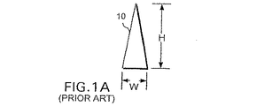
本発明を説明する前に、一般に図1Aおよび図1Bを参照して、従来技術のマイクロニードルの幾つかの例を考慮することが有用である。図1Aは、略円錐状のマイクロニードル10を示している。このマイクロニードルは、そのベースに沿って測定した幅がWであり、マイクロニードルのベースから頂点まで測定した高さがHである。なお、幅Wは、マイクロニードル10の高さHよりも実質的に短く、また、ベースの幅Wは、マイクロニードル10のベースでの直径に相当している。
(Conventional microneedle)
Before describing the present invention, it is useful to consider some examples of prior art microneedles, generally referring to FIGS. 1A and 1B. FIG. 1A shows a substantially
そのベースの幅が約30μmで且つその高さが約150μmである従来のマイクロニードル(マイクロニードル10と同様)は、アドレスhttp://mems.mirc.gatech.edu/research/biomed.htmlにあるワールドワイドウェブに開示されている。同様に、ベースの幅が0.5μmから10μmの範囲で且つ高さが約100μmであるマイクロニードルは、米国特許第4,969,468号明細書に記載されている。この特許は、具体的に、比較的細長いマイクロニードルとなるべく、マイクロニードルのベースの幅に対するマイクロニードルの高さの比が10:1程度でなければならないことを教示している。米国特許第5,457,041号明細書は、ベースの幅が0.5μmから3.0μmで変化し且つ高さが10μmから25μmであるマイクロニードルを開示している。すなわち、これらの3つの各情報源は、その高さがそのベースの幅を少なくとも8:1の比よりも超える従来のマイクロニードルを開示している。 A conventional microneedle having a base width of about 30 μm and a height of about 150 μm (similar to microneedle 10) is available at the address http: // mems. mirc. gatech. edu / research / biomed. It is disclosed on the World Wide Web at html . Similarly, microneedles having a base width in the range of 0.5 μm to 10 μm and a height of about 100 μm are described in US Pat. No. 4,969,468. This patent specifically teaches that for a relatively elongated microneedle, the ratio of the microneedle height to the width of the microneedle base should be on the order of 10: 1. U.S. Pat. No. 5,457,041 discloses a microneedle where the width of the base varies from 0.5 μm to 3.0 μm and the height is from 10 μm to 25 μm. That is, each of these three information sources discloses a conventional microneedle whose height exceeds the width of its base at least a ratio of 8: 1.
図1Bは、略円柱状の従来のマイクロニードル12を示している。このマイクロニードルも、その高さHがそのベースで測定された幅Wを実質的に超える。米国特許第6,033,928号明細書は、そのベースの幅が0.002μmから0.05μmの範囲で且つその高さが0.5μmから2μmの範囲であるマイクロニードル12と同様の形状のマイクロニードルを開示している。すなわち、従来の略円柱状のマイクロニードル12は、幅に対する高さの比が少なくとも4:1である。
FIG. 1B shows a
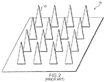
一般に、従来のマイクロニードルは、従来の半導体製造技術を使用して、シリコン系材料によって形成されている。図2に示される従来のマイクロニードルアレー18は、図1Aの複数の従来のマイクロニードル10を組み入れている。従来においては、他のマイクロニードルおよびアレーが開示されているが、それらの形状(高さ:ベース)特性は、図1Aおよび図1Bに示される形状特性および図2に示される形状特性とほぼ同様である。一般に、従来のマイクロニードルは、その高さがそのベースの幅よりも実質的に大きい細長い「スパイク」状あるいは円柱形状の構造体になる傾向がある。
In general, the conventional microneedle is formed of a silicon-based material using a conventional semiconductor manufacturing technique. A
(本発明のマイクロニードル)
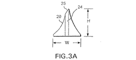
図3Aは、本発明に係るマイクロニードル20を示している。前述した従来のマイクロニードルとは異なり、マイクロニードル20は、そのベースの幅Wがその高さHとほぼ等しい。一実施形態において、幅および高さは約100μmである。しかしながら、この実施例は、単なる典型的な例であり、本発明の範囲を制限しようとするものではない。また、マイクロニードル20は、流体チャンネル24と、傾斜ノンコアリング(non−coring)チップ25とを有している。図3Bは、流体チャンネル24がマイクロニードルを完全に貫通していることを明確に示している。なお、マイクロニードル20の幅Wに対する高さHの比は、ほぼ1:1である。それに対し、従来のマイクロニードルの幅に対する高さの比は、4:1から10:1の範囲である。本発明のマイクロニードルがその高さに対して広い幅を有するベースを有することで、破損し難い強固なマイクロニードルが形成される。
(Microneedle of the present invention)
FIG. 3A shows a microneedle 20 according to the present invention. Unlike the conventional microneedle described above, the
図4は、本発明に係るマイクロニードルの第2の実施形態を示している。マイクロニードル22は、ベースの幅Wがその高さHを超えている、すなわちその高さの約2倍である、ベースを有する。一実施形態において、幅Wは約100μmであり、一方、高さHは約50μmであり、これにより、幅に対する高さの比は、約1:2となる。しかしながら、この場合も、100μmおよび50μmの寸法は、単なる典型例であり、本発明の範囲を制限しようとするものではない。マイクロニードル22の重要な特徴は、その幅に対する高さの比が1:1よりも小さいという点、すなわち、マイクロニードル22がその高さよりも広いベースを有しているという点である。また、マイクロニードル22は、流体チャンネル24’と、ノンコアリングチップ25’とを有している。
FIG. 4 shows a second embodiment of the microneedle according to the present invention. The microneedle 22 has a base whose base width W exceeds its height H, ie about twice its height. In one embodiment, the width W is about 100 μm while the height H is about 50 μm, so that the ratio of height to width is about 1: 2. However, again, the 100 μm and 50 μm dimensions are merely exemplary and are not intended to limit the scope of the present invention. An important feature of the microneedle 22 is that its height to width ratio is less than 1: 1, i.e., the
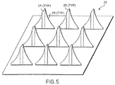
図5は、複数のマイクロニードル20から成るマイクロニードルアレー26を示している。アレー中の各マイクロニードル20は、複数の流体チャンネル24と、ノンコアリングチップ25とを有しており、各マイクロニードル20は、幅に対する高さの比が約1:1である。
FIG. 5 shows a
(マイクロニードルアレーの形成)
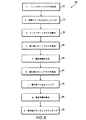
図6のフローチャート28は、本発明に係るマイクロニードルのニードルアレーを形成するために使用されるロジックステップの順序を示している。図7Aから図7Iは、フローチャート28の対応する処理ステップ中における基板材料の断面図を示している。一方、図7Jは、完成したマイクロニードルを示している。
(Formation of microneedle array)
半導体製造産業での使用のために開発されたフォトリソグラフィおよび他の技術を有利に利用して、本発明に係る個々のマイクロニードルおよびマイクロニードルアレーを形成できると考えられる。したがって、シリコンが好ましい基板であると考えられるが、関連技術を使用して扱うことができるゲルマニウム等の他の基板を使用しても良い。一般に、広いベースを有する複数のマイクロニードルを含むアレーは、バッチ処理、半導体製造プロセスで使用されるステップに若干似た以下のステップで製造されることが好ましい。したがって、シリコン基板は、一般に、その上に複数の様々なマイクロニードルアレーが同時に形成される4インチ、6インチ、8インチウエハから成る。しかしながら、図7Aから図7Jには、簡易化のため、1つのマイクロニードルの形成のみが示されている。また、マイクロニードルを構成する様々な層は非常に薄いものであるが、明確にするため、図に示されるこれらの層の寸法がかなり誇張されていることは言うまでもない。 It is believed that photolithography and other techniques developed for use in the semiconductor manufacturing industry can be advantageously utilized to form individual microneedles and microneedle arrays according to the present invention. Thus, although silicon is considered the preferred substrate, other substrates such as germanium that can be handled using related techniques may be used. In general, an array comprising a plurality of microneedles having a wide base is preferably manufactured in the following steps that are somewhat similar to the steps used in batch processing, semiconductor manufacturing processes. Thus, silicon substrates typically consist of 4 inch, 6 inch, and 8 inch wafers on which a plurality of various microneedle arrays are formed simultaneously. However, in FIGS. 7A to 7J, only the formation of one microneedle is shown for simplicity. Also, the various layers that make up the microneedles are very thin, but it will be appreciated that the dimensions of these layers shown in the figures are greatly exaggerated for clarity.
以下のエッチング技術は、本発明に係るマイクロニードルを形成する際に有用であると考えられる。シリコン酸化物、シリコン窒化物、または、シリコン基板を優先的にエッチングするため、反応性イオンエッチング(RIE)プロセスが使用される。この目的のため、一般的なシステムは、5インチの石英電極と1KW、15MHzの高周波(RF)発生器とを有する平行平板反応性イオンエッチング構成を有している。そのようなシステムは、複数のマスフローコントローラと、スロットルバルブ・コントローラ(一定の圧力を維持するため)と、高速ターボ分子真空ポンプとを有していても良い。RIEは、ポリイミド、シリコン窒化物、または、シリコン酸化物等の層を、ウエハ、ウエハ片、または、個々のチップ等のシリコン基板から除去するために使用することができる。シリコン酸化物およびシリコン窒化物をエッチングするために(例えば、カーボンテトラフルオライド、CF4を使用して)、シリコン窒化物に優先してシリコン酸化物をエッチングするために(CF4およびフロオロホルムCHF3を使用して)、シリコン酸化物に優先してシリコンをエッチングするために(シリコンヘキサフルオライドSF6を使用して)、良く知られたプロセスを利用することができる。 The following etching techniques are considered useful when forming the microneedles according to the present invention. A reactive ion etching (RIE) process is used to preferentially etch silicon oxide, silicon nitride, or silicon substrates. For this purpose, a typical system has a parallel plate reactive ion etching configuration with a 5 inch quartz electrode and a 1 KW, 15 MHz radio frequency (RF) generator. Such a system may include a plurality of mass flow controllers, a throttle valve controller (to maintain a constant pressure), and a high speed turbomolecular vacuum pump. RIE can be used to remove layers of polyimide, silicon nitride, or silicon oxide from a silicon substrate such as a wafer, wafer piece, or individual chip. To etch silicon oxide and silicon nitride (eg, using carbon tetrafluoride, CF 4 ), to etch silicon oxide in preference to silicon nitride (CF 4 and fluoroform CHF 3 In order to etch silicon over silicon oxide (using silicon hexafluoride SF 6 ), a well-known process can be used.
前述したシステム等の市販されているシステムは、クックバキューム社(Cooke Vacumn Corporation)のモデルC71/3プラズマシステムである。殆どの材料におけるエッチング速度は、400から600オングストローム/分である。シリコン酸化物におけるエッチング速度は、約±3%まで制御することができる。クックシステムのRF周波数は14.56MHzであり、RF電力は最大1000ワットまで変えることができる。プロセス圧力は、50mtorr未満から1000mtorrを超える範囲で可能である。石英から成る上側電極および下側電極は、閉回路液冷である。マニホールドで複合ガスミキシングを利用することができる。 A commercially available system, such as the system described above, is a Model C71 / 3 plasma system from Cooke Vacuum Corporation. The etch rate for most materials is 400 to 600 angstroms / minute. The etching rate in silicon oxide can be controlled to about ± 3%. The RF frequency of the cook system is 14.56 MHz and the RF power can vary up to 1000 watts. Process pressures can range from less than 50 mtorr to more than 1000 mtorr. The upper and lower electrodes made of quartz are closed circuit liquid cooled. Complex gas mixing can be used in the manifold.
また、RIEの他、ウェットエッチングを有利に使用して、本発明に係るマイクロニードルを形成するために必要なエッチングを行なうこともできる。ウェットエッチングは、液体化学物質を使用してデバイスの周囲の材料を除去し或いは基板表面から薄膜を除去する技術である。この技術は、デバイスまたは基板を純粋な化学物質または化学物質の混合物中に所定時間だけ浸漬することを伴う。必要とされる時間は、除去される層の組成および厚さ、エッチング液、温度によって決まる。デバイスまたは基板上の交互の層を除去するために、一連の化学物質が必要とされても良い。 In addition to RIE, wet etching can be advantageously used to perform etching necessary to form the microneedle according to the present invention. Wet etching is a technique that uses liquid chemicals to remove the material around the device or to remove a thin film from the substrate surface. This technique involves immersing the device or substrate in a pure chemical or mixture of chemicals for a predetermined time. The time required depends on the composition and thickness of the layer to be removed, the etchant, and the temperature. A series of chemicals may be required to remove alternating layers on the device or substrate.
ウェットエッチングを使用して、有機材料、シリコン、ポリイミド、メタライゼーション、ポリシリコン、または、シリコン酸化物およびシリコン窒化物の層を除去することができる。エッチングに利用できる多くの化学物質のうちの幾つかには、フッ化水素酸、塩酸、硫酸、硝酸、リン酸、酢酸、過酸化水素、三酸化クロム、水酸化ナトリウム、水酸化カリウム、水酸化アンモニウム、フッ化アンモニウムが含まれる。エッチング時間は、30秒から24時間の範囲であり、エッチング温度、エッチングされる材料の組成および厚さによって決まる。 Wet etching can be used to remove organic material, silicon, polyimide, metallization, polysilicon, or layers of silicon oxide and silicon nitride. Some of the many chemicals available for etching include hydrofluoric acid, hydrochloric acid, sulfuric acid, nitric acid, phosphoric acid, acetic acid, hydrogen peroxide, chromium trioxide, sodium hydroxide, potassium hydroxide, hydroxide Ammonium and ammonium fluoride are included. The etching time ranges from 30 seconds to 24 hours and depends on the etching temperature, the composition and thickness of the material being etched.
図6を参照すると、ロジックは、ブロック30から開始される。このブロック30では、適当な基板上にドットパターンマスクが形成される。前述したように、シリコンが好ましい基板材料である。図7Aは、シリコン基板50の上面に堆積されるマスク52を示している。マスク52は、円形穴56を有している。穴56は、形成されるマイクロニードルの流体チャンネルのための所望の場所に対応する位置に設けられている。なお、マイクロニードルのアレーを形成するため、基板50の大部分に複数の穴56が形成される。各穴は、基板材料上に形成されるマイクロニードルの場所に対応している。形成される穴56の数に関係無く、ドットパターンマスク中の穴のサイズ(直径)は、完成したマイクロニードルアレーにおける流体チャンネルのサイズと略同一である。
Referring to FIG. 6, the logic begins at
標準的なフォトリソグラフィ技術を使用して、あるいは、半導体産業で一般的に使用される他のマスキング技術を使用して、マスク52を形成することができる。シリコン二酸化物の層をシリコン基板上50に堆積させた後、そのシリコン二酸化物の層の所望の場所に穴56を形成することにより、マスク52が構成されると期待される。
The
ドットパターンマスクが形成されたら、ロジックは、ブロック32へと移り、図7Bに示されるように、穴56によって画定される場所で基板をエッチングすることにより、流体チャンネル58が形成される。穴56によって画定される領域以外の全ての領域では、基板がドットパターンマスクによって覆われているため、エッチングされる基板の部分は、穴56の場所に対応する部分だけである。水酸化カリウム(KOH)溶液を使用するウェットエッチング等の従来のバルクマシニングエッチングプロセスを有利に使用できると考えられる。そのようなエッチングプロセスにおいて、マスク層は、エッチングに使用される化学物質に対して基板よりも十分に耐性がある。すなわち、基板は、マスクが除去される前に完全にエッチングされる。エッチングプロセスは、基板が完全にエッチングされてマイクロニードルおよび支持基板を完全に貫通する流体チャンネル58が形成されるまで続けられることが好ましい。しかしながら、流体チャンネルが基板材料を完全に貫通しないことが望ましい場合には、特定の深さまでにエッチングプロセスを制御することもできる。流体チャンネルの目的は、マイクロニードルの頂点と流体供給源または流体受けリザーバ(ここには図示されていない。図9および図11を参照)との間に流路を形成することであるため、エッチングプロセスが基板を完全にエッチングしない場合、所望の流路を完成するために別個のステップが必要になる。なお、前述したRIEエッチングプロセスを使用して、シリコン酸化物層を傷付けることなく、シリコン基板をエッチングすることもできる。当業者であれば分かるように、このステップでは、複数の他のエッチング技術を有利に使用することができ、また、前述した技術は、好ましい手法の単なる典型例であり、本発明の範囲を制限しようとするものではない。
Once the dot pattern mask is formed, the logic moves to block 32 where a
流体チャンネル58が基板にエッチングされたら、ロジックはブロック34に進み、ドットパターンマスクが除去される。ドットパターンマスクの除去は、エッチングプロセスの逆である。これは、基板を溶解するよりも早くマスクを溶解する化学物質が使用されるからである。そのようなマスク除去技術は、技術的に良く知られている。図7Cは、このステップの結果を示している。図7Cでは、図7Aおよび図7Bに見えるドットパターンマスク52がシリコン基板50から完全に除去されている。
Once the
ここで、ロジックは、図6のブロック36である4番目のステップへと進む。このステップでは、窒化物パターンマスクが形成される。図7Dは、このステップを示している。図7Dにおいては、窒化物パターンマスク60がシリコン基板50上に形成されている。なお、窒化物パターンマスクが無いシリコン基板50の領域も形成されている。具体的には、窒化物パターンマスクは、穴58の内面、シリコン基板50の下面、流体チャンネル58に通じる開口の周囲の肩部領域62、64に形成されない。特に、流体チャンネルの一方側の肩部領域62は、反対側の肩部領域64よりも十分小さい。肩部領域62と肩部領域64との間のサイズの違いの重要性については、以下の形成プロセスにおけるその後のステップの説明で明らかになる。なお、肩部領域におけるこの違いにより、本発明における傾斜ノンコアリングチップを形成することができる。シリコン二酸化物の層を有利に使用して窒化物パターンマスク60を形成できると考えられる。
The logic now proceeds to the fourth step, block 36 of FIG. In this step, a nitride pattern mask is formed. FIG. 7D illustrates this step. In FIG. 7D, a
窒化物パターンマスクが形成されたら、ロジックはブロック38に進む。このブロックにおいては、窒化物パターンマスク60によって覆われていなかった全ての領域で窒化物層が成長される。図7Eは、窒化物層66が成長した窒化物層成長ステップの結果を示している。なお、窒化物層66は、シリコン基板50の下面、流体チャンネル58の肩部62、64および壁を覆っている。窒化物層66を成長させる1つの方法では、アンモニア(NH3)の存在下でジクロロシラン(SiH2Cl2)の低圧化学蒸着(LPCVD)を使用して、約1/2Torrの圧力および約820℃の温度で、300から700オングストロームの厚い窒化物層が形成される。当業者であれば分かるように、窒化物層66を形成する他の方法を使用することができ、また、前述した技術は、好ましい手法の単なる典型例であるが、本発明の範囲を制限しようとするものではない。
Once the nitride pattern mask has been formed, the logic proceeds to block 38. In this block, a nitride layer is grown in all regions not covered by the
窒化物層66が成長されたら、ロジックは図6のブロック40へと移る。このブロックにおいては、窒化物パターン60が除去されて、窒化物層66で覆われていないシリコン基板50の部位が露出される。図7Fは、シリコン基板50、窒化物層66、穴58、肩部62、64を示している。マスクすなわち窒化物層は、シリコン基板50の上面の領域63を覆っていない。窒化物層66によって覆われた基板50の部位を除去することなく、エッチングによって領域63を優先的に除去することができる。なお、肩部62、64の窒化物層66は、図7Dの窒化物マスク60で画定されたオフセットパターンを模倣している。
Once the
窒化物パターン60が除去されたら、ロジックは、図6のブロック42に移る。このブロックでは、領域63上で異方性ベベルエッチングが行なわれる。図7Gは、プロセスにおけるこの7番目のステップ後に得られる結果を示している。当業者であれば分かるように、シリコン基板と共に使用するために、幾つかの様々なエッチングプロセスを利用することができる。特に、異方性エッチングは、鋭い角度の境界部の形成によって特徴付けられる。等方性エッチングプロセスで見られる非常に丸みのある(rounded)エッチングとは異なり、異方性エッチングを使用して、斜め形状の溝または側壁を形成することができる。異方性エッチングにおいて、側壁は、表面よりもかなりゆっくりとエッチングされる。その結果、鋭い境界部が形成され、アスペクト比が高い構造体を形成することができる。テトラメチルアンモニア水酸化物(N,N,N−トリメチル−メタナミニウム水酸化物、すなわち、TMAH)は、異方性エッチングを行なうために使用される幾つかのエッチング液のうちの1つである。なお、鋭く形成される角度のある或いは傾斜した表面68が図7Gのシリコン基板50に形成された。また、異方性エッチングは「ベベル」エッチングとも呼ばれ、一方、等方性エッチングは、「ラウンディング」エッチングとも呼ばれる。
Once the
その後、ロジックは、図6のブロック42に移る。このブロックにおいては、窒化物層66が除去される。前述したように、RIEまたは湿式化学処理を使用して、窒化物層66を優先的に除去することができる。また、当業者であれば分かるように、窒化物層66を除去する他の方法を代わりに使用することができる。図7Hは、窒化物層を除去した後に得られる結果を示している。
Thereafter, the logic moves to block 42 of FIG. In this block, the
最後に、ロジックは、等方性ラウンディングエッチングが行なわれることを示すブロック44に進む。なお、窒化物層66が除去されたため、肩部62、64はもはや保護されない。したがって、等方性エッチングプロセスにおいては、肩部62、64にあるシリコン基板50の部分が除去され、これにより、本発明に係るマイクロニードルのノンコアリングチップが形成される。前述したように、等方性エッチングは、異方性エッチングで形成される非常に角度がある面とは異なり、曲面70等の丸みのある面を形成することによって特徴付けられる。
Finally, the logic proceeds to block 44 indicating that an isotropic rounding etch is to be performed. Note that the
図7Jは、図6および図7Aから図7Iに示されたステップを使用して形成されたマイクロニードル22aを示している。マイクロニードル22aの幅Wに対する高さHの比は、1:2よりも小さい。なお、図7Jの完成したマイクロニードル22aにおける幅Wに対する高さHの比を変えるため、図7Aの当初のシリコン基板50のサイズおよび形状を操作することができる。図7Aの基板がより厚いと、図7Jの高さHがより高いマイクロニードルが形成される。また、図7Gの異方性エッチングステップにより、完成されたマイクロニードル22aにおける高さHが得られる。エッチング時間が短いと、高さHが低くなり、一方、エッチング時間が長いと、高さHが高くなる。
FIG. 7J shows a
(マイクロニードルアレーの用途)
本発明の他の態様は、前述したように構成されたマイクロニードルアレーの診断装置での使用に関するものである。図8は、例えば手持ち式の診断装置80を示している。手持ち式の診断装置80は、ハウジング81と、ディスプレイ82と、キーボード84と、診断カートリッジ86とを有している。なお、診断カートリッジ86は、手持ち式診断装置80から取り外すことができる。使用中、診断カートリッジ86は、手持ち式診断装置80から取り外されて、ユーザの皮膚の一部、例えばユーザの腕88と接触するように配置される。後述するように、診断カートリッジにより患者またはユーザの体から血液が引き出され、これにより、患者の血液を保持する診断カートリッジを診断装置80に戻した際に、診断装置で分析を行なうことができる。
(Use of microneedle array)
Another aspect of the present invention relates to the use of a microneedle array configured as described above in a diagnostic device. FIG. 8 shows a hand-held
なお、用語「ユーザ」および「患者」は、この明細書および以下の請求の範囲の全体にわたって、置き換え可能に使用される。本発明は、患者である他の人を治療する医者であるユーザによって使用可能であり、あるいは、患者であるユーザが本発明を直接に使用できることは言うまでもない。 It should be noted that the terms “user” and “patient” are used interchangeably throughout this specification and the following claims. It will be appreciated that the present invention can be used by a user who is a doctor treating another person who is a patient, or a user who is a patient can use the present invention directly.
図9は、図8の概略図には図示されていない手持ち式の診断装置80の別の機能的要素を示している。プロセッサ85は、メモリ87およびキーパッド84に双方向接続されている。ディスプレイ82は、プロセッサ85に制御可能に接続されている。取り外し可能な診断カートリッジ86は、ハウジング81内に適切に挿入されると、プロセッサ85に電気的に接続され、これにより、診断カートリッジ86によって収集された任意のデータがプロセッサ85に通信される。プロセッサ85は、診断カートリッジによって与えられる信号に基づいて診断ルーチンを実行するとともに、その結果をディスプレイ82上に表示するようにプログラムされている。メモリ87は、プロセッサに診断ルーチンを実行させ且つ結果を表示させる機械命令が記憶されている読み出し専用メモリ(ROM)と、ランダム・アクセス・メモリ(RAM)(いずれのメモリのタイプも別個に示されていない)とを有していることが好ましい。メモリ87は、プロセッサ85に双方向接続されている。
FIG. 9 shows another functional element of the hand-held
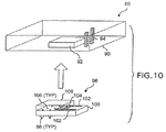
図10は、診断カートリッジ86の更なる詳細を示している。図10には、マイクロニードルアレー96の詳細を見ることができるように、診断マイクロニードルアレー96が診断カートリッジ86から分解された状態で示されているが、診断マイクロニードルアレー96は、その完全に組み立てられた状態において、診断カートリッジ86のキャビティ92内に挿入されることは言うまでもない。診断カートリッジ86は、ハウジング90と、複数の導電体94と、キャビティ92とを有している。
FIG. 10 shows further details of the
診断マイクロニードルアレー96はシリコン基板100を有している。シリコン基板100上には、複数のマイクロニードル98が形成されている。なお、各マイクロニードル98は、基板100およびマイクロニードルを完全に貫通する対応する流体チャンネル106を有している。図10に示されるように、マイクロニードル98は、基板100の下側に配置されている。基板100の上側には、センサ104および複数の電気接点102が配置されている。センサ104および電気接点102は、基板100に付加される別個の構成部品であっても良い。しかしながら、センサ104および電気接点102は、半導体製造技術を使用して、マイクロニードル98とは反対側のシリコン基板100上に形成されることが好ましい。電気接点102は、ハウジング90内の導電体94と接触するように位置決めされている。センサ104のために使用される構成は、診断カートリッジ86が行なうと期待される診断処置のタイプによって決まり、意図される用途に基づいて変更することができる。例えば、グルコースに反応するセンサの1つのタイプは、糖尿病患者の血糖値を測定するために使用される。したがって、糖尿病を持つ人は、手持ち式診断装置80と、血糖値レベル(血液の100ミリリットル毎にグルコースをミリグラム単位で測定する)を監視するように形成された診断カートリッジ86とを使用することができる。
The
図10は、診断マイクロニードルアレー96に関連付けられた流体リザーバ108を更に示している。一実施形態において、流体リザーバ108は、ハウジング90内のキャビティ92の壁によって形成される。他の実施形態において、流体リザーバ108は、シリコン基板100上に装着され且つキャビティ92内に嵌まり込むサイズに設定された別個のプラスチックハウジングによって形成される。
FIG. 10 further illustrates a
図11は、診断マイクロニードルアレー96の側面図を示している。流体チャンネル106は、基板100およびマイクロニードル98の両方を完全に貫通している。図8に示されるように診断カートリッジがユーザの皮膚に貼り付けられると、これらの穴を通じて流体(例えば、ユーザの血液)が流体リザーバ108内に引き上げられる。流体がセンサ104に接触し、診断カートリッジが診断カートリッジ86のキャビティ92内に挿入されると、センサ104からの電気信号は、診断カートリッジ86の導電体94に接続された導線102に沿って送信される。
FIG. 11 shows a side view of the
操作時、ユーザは、診断カートリッジ86を握るとともに、診断マイクロニードルアレー96のマイクロニードル98がユーザの皮膚に隣接して配置されるように診断カートリッジを設置する。ユーザは、ユーザの皮層にマイクロニードル98を刺入できるように、弱い圧力を診断カートリッジ86に加える。ユーザの少量の血液は、流体チャンネル106を通じて、流体リザーバ108内へと引き出される。ユーザの血液がセンサ104と接触すると、センサ104によって測定されたパラメータを示す電気信号が、電気接点102から導電体94へと送られる。その後、ユーザが診断カートリッジ86を手持ち式診断装置80に戻し、導電体94が手持ち式診断装置の対応する電気接点に接続する。これにより、センサ信号およびセンサ信号が運ぶデータが、プロセッサ85に送られる。プロセッサ85に供給された信号は、メモリ87内に記憶された機械命令にしたがって処理される。結果は、ディスプレイ82を介してユーザに表示される。ユーザは、キーパッド84を使用して、プロセッサ85がセンサ信号データを適切に処理するために必要な患者の固有のデータを入力することができる。
In operation, the user holds the
図12は、図8に示された診断ユニット80と同じ構成部品の多くを含む手持ち式薬物供給ユニット110を示している。診断ユニットおよび薬物供給ユニットの両方において、同じ手持ち式ユニットが使用されると期待される。手持ち式薬物供給ユニット110は、ハウジング111と、ディスプレイ114と、キーパッド112と、薬用流体供給源116(手持ち式薬物供給ユニット110を形成するために、診断ユニット80の診断カートリッジ86を交換する)とを有している。流体ライン118は、薬用流体供給源116を供給カートリッジ124に接続している。また、電気ライン120は、手持ち式薬物供給ユニット110を供給カートリッジに接続している。ユーザは、薬用流体を供給すべき場所の皮層上に供給カートリッジ124が配置される(図では、供給カートリッジ124がユーザまたは患者の腕122上に配置されている)ように、供給カートリッジ124を位置決めする。
FIG. 12 shows a handheld
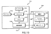
図13は、図12の概略図に図示されていない手持ち式薬物供給ユニット110および供給カートリッジ124の別の機能的要素を示している。プロセッサ115は、メモリ117およびキーパッド112に双方向接続されている。また、ディスプレイ114は、流体供給源116と同様に、プロセッサ115に接続されている。メモリ117は、機械命令が記憶されるROMおよびRAMを有している。供給カートリッジ124は、ハウジング126と、流体供給源116と流体連通する流体リザーバ136と、プロセッサ115に電気的に接続された変換器(transducer)アレー130とを有している。また、供給カートリッジ124は、流体リザーバ136と流体連通するマイクロニードルアレー140を有している。
FIG. 13 shows another functional element of the handheld
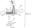
図14は、供給カートリッジ124aの部分分解図を示している。供給カートリッジ124aは、供給カートリッジ124に存在しない別個の要素を有している。この別個の要素は、マイクロニードル144を患者の皮層またはユーザの皮層に刺入させることができる十分な力でマイクロニードルアレー140を皮層内へと付勢する付勢力を形成するスプリングアセンブリ132である。また、図14は、変換器アレー130を手持ち式薬物供給システム110に電気的に接続する方法および流体リザーバ136を手持ち式薬物供給システム110に流体連通状態で接続する方法の詳細を示している。供給カートリッジ124aは、超音波変換器130を電気ライン120に接続する電気接点128を有している。電気ラインは、手持ち式薬物供給システム110のプロセッサ115に接続されている。流体通路138は、流体リザーバ136に流体連通するとともに、手持ち式薬物供給システム110の流体供給源116に接続する流体ライン118にも流体連通している。
FIG. 14 shows a partially exploded view of the
スプリングアセンブリ132は、流体チャンバ136の真上で、ハウジング126の上部に装着されている。マイクロニードルアレー140は、流体チャンバ136内に嵌まり込むように形成されている。図12は、マイクロニードルアレー140に関する詳細をより明確に見ることができるように、供給カートリッジ124aから分解されたマイクロニードルアレー140を示している。しかしながら、マイクロニードルアレーは、通常の状況下で、ハウジング126内に装着されるように形成される。マイクロニードルアレー140は、その上に複数のマイクロニードル144が形成されるシリコン基板146を有している。複数の穴142が基板146およびマイクロニードル144を完全に貫通している。前述したように、基板においては、ゲルマニウム等の他の材料を使用することができる。
The
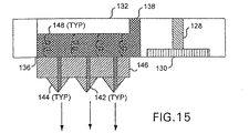
図15は、マイクロニードルアレー140の更なる詳細を示している。この図においては、基板146およびマイクロニードル144を完全に貫通する穴142を明確に見ることができる。複数のバネ148は、基板146をスプリングアセンブリ132に接続するとともに、バネが圧縮された後に急に解放されて伸張すると、マイクロニードルを皮層に刺入させることができる付勢力を作用させるようになっている。これにより、マイクロニードルアレーがユーザの皮膚に接触された状態で、マイクロニードルアレーに対して付勢力が作用する。流体チャンバ136、流体通路138、穴142は、協働して、薬用流体をユーザに供給する。なお、図15は、マイクロニードルアレー140およびバネ148を伸張位置で示している。
FIG. 15 shows further details of the
スプリングアセンブリ132およびバネ148を有さない他の実施形態においては、代わりに、マイクロニードルアレー140が供給カートリッジ内に固定され、供給カートリッジは、マイクロニードルがユーザの皮層に対向して配置されるように位置決めされる。その後、供給カートリッジ124に対して単に手で十分な圧力を加えることにより、ユーザの皮層に貫通させることができる。
In other embodiments without the
図16は、流量センサ156および流量制御弁158を有するマイクロニードル部材150を示している。マイクロニードル部材150は、供給カートリッジ124、124aのマイクロニードルアレー140の代わりに使用することができる。マイクロニードル部材150は、基板141と、流体チャンネル143と、マイクロニードル145とを有している。簡易化のため、1つのマイクロニードルおよび穴だけが図示されているが、複数のマイクロニードルおよび流体チャンネルをマイクロニードル部材150に有利に組み込むことができることは言うまでもない。複数のマイクロニードルおよび流体チャンネルが含まれる場合には、複数のセンサおよび流体制御弁(各マイクロニードル毎に1つ)が含まれなければならず、あるいは、複数のマイクロニードルに必要な範囲で流体を流すことができる十分な大きさにセンサ156および流量制御弁158を寸法付けなければならない。例えば、マイクロニードル部材150がマイクロニードルのアレー内に組み込まれる場合、少なくともアレーの幅と同じ幅を有する1つのセンサおよび1つの流量制御弁が必要とされるかもしれない。
FIG. 16 shows a
流量センサ156は、別個に形成されて基板141に取り付けることができ、あるいは、従来の半導体製造技術を使用して、流量センサ156を基板141上に形成することができる。また、従来の半導体製造技術を使用して流量制御弁158を形成できるように、ハウジング152はシリコンから形成されることが好ましい。しかしながら、他の製造技術を使用しても良い。薬用流体をマイクロニードル部材150内に流入させることができるように、穴154は、ハウジング152の上部に配置される。
The
図17は、流体供給源116の実施形態の別の詳細を提供している。図12に示される場合と同様に、流体供給源116は、手持ち式供給システム110内に配置される。流体供給源116は、内部に収容された薬用流体が完全に分配されると交換される使い捨てユニットにできることを想定している。流体供給源116は、上側ハウジング166と、複数の電気機械アクチュエータ164と、自己密封式のエラストマー膜162と、サブミクロンフィルタ168とを有していることが好ましい。
FIG. 17 provides another detail of an embodiment of the
電気機械アクチュエータは、技術的に知られている。そのようなアクチュエータは、シールされたチャンバ内の流体に電圧を印加する。この電圧によって、流体がガスを形成する。このガスは、チャンバ内の圧力を高め、これにより、所望の機械的な動作力が形成される。電圧が除去されると、ガスは、流体によって再吸収された後、要求通りにプロセスを繰り返すべく電気的に活性化され得る。幾つかの電気化学的なアクチュエータは、電圧の印加に応じて可逆的に酸化される流体を使用する。そして、電圧が除去されると、対応する還元反応により、流体がその元の状態に戻る。 Electromechanical actuators are known in the art. Such an actuator applies a voltage to the fluid in the sealed chamber. This voltage causes the fluid to form a gas. This gas increases the pressure in the chamber, thereby creating the desired mechanical operating force. When the voltage is removed, after the gas is reabsorbed by the fluid, it can be electrically activated to repeat the process as required. Some electrochemical actuators use fluids that are reversibly oxidized in response to an applied voltage. When the voltage is removed, the fluid returns to its original state by the corresponding reduction reaction.
流体供給源116を満たすため、注射器(図示せず)が自己密封式のエラストマー膜162に穿刺される、これにより、薬用流体を注射器から流体供給源116の内部へと注入することができる。アクチュエータ164が流体供給源116の内部の流体に対して駆動圧を与えていない場合、流体は、サブミクロンフィルタ168を貫通しない。しかしながら、適切な作動圧がアクチュエータ164によって与えられると、流体は、サブミクロンフィルタ168を貫通して、チャンバ170内に流入し、流体ライン118へと流れる。
To fill the
一般に、ユーザが薬物供給システム110を使用できる状態になると、最初のステップは、所望の薬用流体供給源116がユニット110内に挿入されるようにすることである。一人のユーザが薬物供給システム110を使用して複数のタイプの薬用流体を投与でき、また、そのようなユーザが様々なタイプの薬用流体を収容する複数の薬用流体供給源116を有することが期待される。その後、ユーザは、キーパッド112を使用して、所望の供給速度等のユーザデータを入力する。そのような情報を使用して、プロセッサ115は、流体供給源116からの流体の流量を制御することにより、供給速度を制御することができる。好ましい実施形態において、プロセッサ115は、アクチュエータ164によって供給される圧力を制御して、所望の流体供給速度を与える。ユーザは、ユーザの皮層の所望部位に供給カートリッジ124を位置決めする。一般に、この部位は、ユーザまたは患者の腕にあるが、患者の皮層の他の部位を使用して、経皮的に薬用流体を注入することができる。
In general, once the user is ready to use the
図15を参照すると、特に望ましい対象部位を選択できるように、超音波変換器アレー130が含まれている。超音波変換器130は、超音波信号を患者の体に伝達するとともに、反射した信号を受けて、内部構造を示す対応する信号を形成し、その信号を電気ライン120を介して手持ち式供給システム110に送る。プロセッサ115は、変換器アレー130からの信号を監視し、ユーザが自分の皮膚にわたって供給カートリッジ124を移動させることにより所望の場所が見つかると、プロセッサ115により、ディスプレイ114は、供給カートリッジ124が所望の位置にあることをユーザに警告する。この時点で、光圧を使用してマイクロニードル144を皮層に挿通させることにより、あるいは、バネ148を使用してマイクロニードルを皮層に挿通させることにより、供給カートリッジ124は、皮層を通じて、制御された量の薬用流体を患者に供給し始める。患者の皮膚の特徴に基づいて、あるいは、患者の体の内部の状態に基づいて、適した位置を決定することができる。例えば、超音波変換器を使用して、傷付いた内部の柔らかい組織に隣接する皮層上の位置を決定し、これにより、その場所で供給カートリッジ124を使用して鎮痛剤及び/又は抗炎症薬を患者に注入できるようにすることが適している場合もある。
Referring to FIG. 15, an
本発明を実行する好ましい形式に関して本発明を説明してきたが、当業者であれば分かるように、これらに対しては、添付の特許請求の範囲内で、多くの変更を成すことができる。したがって、本発明の範囲は、どんな形であれ、前述した説明によって制限されるものではなく、専ら、添付の特許請求の範囲を参照することにより決定されるものである。 Although the invention has been described in terms of a preferred form of implementing the invention, it will be apparent to those skilled in the art that many changes can be made therein within the scope of the appended claims. Accordingly, the scope of the invention is not limited in any way by the foregoing description, but is solely determined by reference to the appended claims.
独占的な権利が要求されている本発明は、添付の特許請求の範囲によって規定される。 The invention in which an exclusive right is required is defined by the appended claims.
Claims (22)
(a)ハウジングと、プロセッサと、前記プロセッサに電気的に接続されたディスプレイと、前記プロセッサに電気的に接続されたキーパッドと、前記プロセッサに電気的に接続されたメモリとを備えた手持ち式診断ユニットと、
(b)ハウジングとマイクロニードルアレーとを備え、患者から前記生物学的流体のサンプルを得るための使い捨て可能なカートリッジと、
(c)前記生物学的流体のサンプルと接触する時に、前記生物学的流体の特徴を示す信号を形成し、この信号を前記プロセッサに供給して診断処理を行なうために前記プロセッサに電気的に接続されるようになっているセンサとを備えており、
前記アレーの各マイクロニードルは、
(1)先が尖っており且つ組織に刺入可能な傾斜したノンコアリングチップを有する略円錐形状の本体を備え、
(2)前記円錐形状の本体は、前記チップの反対の端部で基板によって形成された幅広いベースを更に有し、
(3)前記円錐形状の本体を貫通して延び、前記幅広いベースと前記チップとの間を流体連通させる流体チャンネルを備えており、
前記幅広いベースから前記チップまでの距離として定義される各マイクロニードルの高さは、前記幅広いベースの幅よりも実質的に小さい、前記低侵襲的診断システム。In a minimally invasive diagnostic system for extracting and analyzing biological fluids from a patient,
(A) a hand-held device comprising a housing, a processor, a display electrically connected to the processor, a keypad electrically connected to the processor, and a memory electrically connected to the processor; A diagnostic unit;
(B) a disposable cartridge comprising a housing and a microneedle array for obtaining a sample of said biological fluid from a patient;
(C) forming a signal indicative of the characteristics of the biological fluid when contacted with the sample of biological fluid and supplying the signal to the processor for electrical diagnostic processing. With a sensor to be connected ,
Each microneedle of the array is
(1) A substantially conical main body having a pointed tip and an inclined non-coring tip that can be inserted into tissue;
(2) the conical body further has a wide base formed by a substrate at the opposite end of the tip;
(3) includes a fluid channel extending through the conical body and fluidly communicating between the wide base and the tip;
The minimally invasive diagnostic system , wherein the height of each microneedle, defined as the distance from the wide base to the chip, is substantially smaller than the width of the wide base .
(a)ハウジングと、プロセッサと、前記プロセッサに電気的に接続されたディスプレイと、前記プロセッサに電気的に接続されたキーパッドと、前記プロセッサに電気的に接続されたメモリと、薬用流体リザーバと、前記薬用流体リザーバに流体連通する薬用流体出口と、薬用流体を前記薬用流体リザーバから薬用流体出口を介して患者内に注入するための圧力を形成するアクチュエータとを備えた手持ち式制御ユニットであって、前記アクチュエータが前記プロセッサに電気的に接続されて前記プロセッサによって制御される手持ち式制御ユニットと、
(b)ハウジングとマイクロニードルアレーとを備え、前記マイクロニードルアレーを介して薬用流体が患者内に注入される使い捨て可能なカートリッジと、
(c)先端と基端とを有し、前記薬用流体出口と前記使い捨て可能なカートリッジとを流体連通させるために、前記基端が前記薬用流体出口に接続され、前記先端が前記使い捨て可能なカートリッジに接続される流体ラインとを備えており、
前記アレーの各マイクロニードルは、
(1)先が尖っており且つ組織に刺入可能な傾斜したノンコアリングチップを有する略円錐形状の本体を備え、
(2)前記円錐形状の本体は、前記チップの反対の端部で基板によって形成された幅広いベースを更に有し、
(3)前記円錐形状の本体を貫通して延び、前記幅広いベースと前記チップとの間を流体連通させる流体チャンネルを備えており、
前記幅広いベースから前記チップまでの距離として定義される各マイクロニードルの高さは、前記幅広いベースの幅よりも実質的に小さい、前記低侵襲的薬物供給システム。A minimally invasive drug delivery system for transdermally delivering medicinal fluid into a patient,
(A) a housing, a processor, a display electrically connected to the processor, a keypad electrically connected to the processor, a memory electrically connected to the processor, and a medicinal fluid reservoir; A handheld control unit comprising: a medicinal fluid outlet in fluid communication with the medicinal fluid reservoir; and an actuator for creating pressure for injecting medicinal fluid from the medicinal fluid reservoir into the patient through the medicinal fluid outlet. A hand-held control unit in which the actuator is electrically connected to the processor and controlled by the processor;
(B) a disposable cartridge comprising a housing and a microneedle array, through which medicinal fluid is injected into the patient via the microneedle array;
(C) a distal end and a proximal end, wherein the proximal end is connected to the medicinal fluid outlet and the distal end is the disposable cartridge for fluidly communicating the medicinal fluid outlet and the disposable cartridge; And a fluid line connected to the
Each microneedle of the array is
(1) A substantially conical main body having a pointed tip and an inclined non-coring tip that can be inserted into tissue;
(2) the conical body further has a wide base formed by a substrate at the opposite end of the tip;
(3) includes a fluid channel extending through the conical body and fluidly communicating between the wide base and the tip;
The minimally invasive drug delivery system , wherein the height of each microneedle, defined as the distance from the broad base to the tip, is substantially less than the width of the wide base .
(b)前記使い捨てカートリッジは、患者の体内の対象領域へと方向付けられる超音波信号を形成し且つ反射された超音波信号を患者の体内から受けることにより対象領域の状態を示す出力信号を形成する超音波変換器アレーを更に有し、前記超音波変換器アレーは、前記出力信号を送信する前記データケーブルに電気的に接続され、前記プロセッサは、前記出力信号に応答するとともに、前記使い捨て可能なカートリッジが患者の体内の所望の領域に隣接して配置されていることをディスプレイ上でユーザに示す、請求項11に記載の低侵襲的薬物供給システム。(A) having a proximal end and a distal end, wherein the proximal end of the data cable is electrically connected to the processor by being connected to the handheld control unit, and the distal end of the data cable is disposable Further comprising a data cable electrically connected to the cartridge,
(B) The disposable cartridge forms an ultrasonic signal directed to a target region in the patient's body and forms an output signal indicating the state of the target region by receiving the reflected ultrasonic signal from the patient's body. An ultrasonic transducer array that is electrically connected to the data cable that transmits the output signal, and wherein the processor is responsive to the output signal and is disposable. 12. The minimally invasive drug delivery system of claim 11 , wherein a minimal cartridge is positioned adjacent to a desired area within a patient to indicate to the user on a display.
(a)シリコンおよびポリシリコンのうちの一方から成る基板を形成するステップと、(A) forming a substrate made of one of silicon and polysilicon;
(b)前記基板内に流体チャンネルを形成して、前記流体チャンネルが前記基板を貫通するようにするステップと、(B) forming a fluid channel in the substrate such that the fluid channel penetrates the substrate;
(c)前記基板のかなりの部分を除去することにより、残存部分を残すステップであって、該残存部分は、前記流体チャンネルを取り囲むとともに、略円錐形状を成し、これにより、前記流体チャンネルが、前記円錐形状の中心軸にほぼ沿って配置されるステップとを含んでおり、(C) removing a substantial portion of the substrate to leave a remaining portion, the remaining portion surrounding the fluid channel and having a generally conical shape, whereby the fluid channel is And a step disposed substantially along the central axis of the conical shape,
(d)前記基板のかなりの部分を除去するステップが、前記円錐形状の頂点に斜角を付けることを含み、(D) removing a substantial portion of the substrate comprises beveling the apex of the conical shape;
(e)前記流体チャンネルを形成するステップが、(E) forming the fluid channel comprises:
(1)前記基板の上面に第1のマスクを形成するステップと、(1) forming a first mask on the upper surface of the substrate;
(2)第1のマスクに形成された穴を通じて前記基板をエッチングして、前記流体チャンネルを形成するステップと、(2) etching the substrate through a hole formed in the first mask to form the fluid channel;
(3)前記第1のマスクを除去するステップとを含み、(3) removing the first mask;
(f)前記基板のかなりの部分を除去する前記ステップが、(F) the step of removing a significant portion of the substrate;
(1)第2のマスクを形成するステップと、(1) forming a second mask;
(2)窒化物層を堆積させるステップと、(2) depositing a nitride layer;
(3)前記第2のマスクを除去するステップと、(3) removing the second mask;
(4)前記基板をエッチングして、前記基板のかなりの部分を除去するステップとを含む、前記方法。(4) etching the substrate to remove a substantial portion of the substrate.
Applications Claiming Priority (2)
| Application Number | Priority Date | Filing Date | Title |
|---|---|---|---|
| US09/880,377 US6767341B2 (en) | 2001-06-13 | 2001-06-13 | Microneedles for minimally invasive drug delivery |
| PCT/US2002/016323 WO2002100474A2 (en) | 2001-06-13 | 2002-05-22 | Microneedles for minimally invasive drug delivery and method of manufacturing the same |
Publications (3)
| Publication Number | Publication Date |
|---|---|
| JP2005503194A JP2005503194A (en) | 2005-02-03 |
| JP2005503194A5 JP2005503194A5 (en) | 2006-01-05 |
| JP4286131B2 true JP4286131B2 (en) | 2009-06-24 |
Family
ID=25376125
Family Applications (1)
| Application Number | Title | Priority Date | Filing Date |
|---|---|---|---|
| JP2003503290A Expired - Fee Related JP4286131B2 (en) | 2001-06-13 | 2002-05-22 | Microneedle for minimally invasive drug supply and method for producing microneedle |
Country Status (9)
| Country | Link |
|---|---|
| US (2) | US6767341B2 (en) |
| EP (2) | EP1695734B1 (en) |
| JP (1) | JP4286131B2 (en) |
| AT (1) | ATE397473T1 (en) |
| AU (1) | AU2002312013A1 (en) |
| CA (1) | CA2450367C (en) |
| DE (2) | DE60217510T2 (en) |
| ES (2) | ES2308657T3 (en) |
| WO (1) | WO2002100474A2 (en) |
Families Citing this family (223)
| Publication number | Priority date | Publication date | Assignee | Title |
|---|---|---|---|---|
| IL134997A0 (en) * | 2000-03-09 | 2001-05-20 | Yehoshua Yeshurun | Health care system based on micro device |
| US6533949B1 (en) * | 2000-08-28 | 2003-03-18 | Nanopass Ltd. | Microneedle structure and production method therefor |
| KR20030068136A (en) * | 2000-10-13 | 2003-08-19 | 알자 코포레이션 | Apparatus and method for piercing skin with microprotrusions |
| US7108681B2 (en) * | 2000-10-16 | 2006-09-19 | Corium International, Inc. | Microstructures for delivering a composition cutaneously to skin |
| US7828827B2 (en) | 2002-05-24 | 2010-11-09 | Corium International, Inc. | Method of exfoliation of skin using closely-packed microstructures |
| US6663820B2 (en) * | 2001-03-14 | 2003-12-16 | The Procter & Gamble Company | Method of manufacturing microneedle structures using soft lithography and photolithography |
| US6749792B2 (en) * | 2001-07-09 | 2004-06-15 | Lifescan, Inc. | Micro-needles and methods of manufacture and use thereof |
| SE0102736D0 (en) * | 2001-08-14 | 2001-08-14 | Patrick Griss | Side opened out-of-plane microneedles for microfluidic transdermal interfacing and fabrication process of side opened out-of-plane microneedles |
| US20030044318A1 (en) * | 2001-09-05 | 2003-03-06 | Lorin Olson | Devices for analyte concentration determination and methods of using the same |
| US20040087992A1 (en) * | 2002-08-09 | 2004-05-06 | Vladimir Gartstein | Microstructures for delivering a composition cutaneously to skin using rotatable structures |
| DE10238266A1 (en) * | 2002-02-28 | 2003-11-06 | Ibidi Gmbh | Microfluidic system |
| WO2004033021A1 (en) * | 2002-10-07 | 2004-04-22 | Biovalve Technologies, Inc. | Microneedle array patch |
| US7578954B2 (en) * | 2003-02-24 | 2009-08-25 | Corium International, Inc. | Method for manufacturing microstructures having multiple microelements with through-holes |
| US7415299B2 (en) * | 2003-04-18 | 2008-08-19 | The Regents Of The University Of California | Monitoring method and/or apparatus |
| EP1632263A4 (en) * | 2003-06-10 | 2008-04-30 | Medrx Co Ltd | Process for producing pad base for transdermal drug administration, pad base for transdermal drug administration and needle |
| US7920906B2 (en) | 2005-03-10 | 2011-04-05 | Dexcom, Inc. | System and methods for processing analyte sensor data for sensor calibration |
| US9247900B2 (en) | 2004-07-13 | 2016-02-02 | Dexcom, Inc. | Analyte sensor |
| US20050228313A1 (en) * | 2003-12-04 | 2005-10-13 | University Technologies International Inc. | Fluid sampling, analysis and delivery system |
| GB0402131D0 (en) | 2004-01-30 | 2004-03-03 | Isis Innovation | Delivery method |
| WO2005094526A2 (en) | 2004-03-24 | 2005-10-13 | Corium International, Inc. | Transdermal delivery device |
| US7850676B2 (en) * | 2004-04-19 | 2010-12-14 | The Invention Science Fund I, Llc | System with a reservoir for perfusion management |
| CA2572870A1 (en) * | 2004-07-06 | 2006-01-12 | Transpharma Medical Ltd. | Delivery system for transdermal immunization |
| US20060020192A1 (en) | 2004-07-13 | 2006-01-26 | Dexcom, Inc. | Transcutaneous analyte sensor |
| US20060270922A1 (en) | 2004-07-13 | 2006-11-30 | Brauker James H | Analyte sensor |
| US7086266B2 (en) | 2004-08-05 | 2006-08-08 | Becton, Dickinson And Company | Method of producing tapered or pointed cannula |
| US7076987B2 (en) | 2004-08-05 | 2006-07-18 | Becton, Dickinson And Company | Method of producing tapered or pointed cannula |
| WO2006022933A2 (en) * | 2004-08-05 | 2006-03-02 | Apogee Technologies, Inc. | System and method for drug delivery and microfluidic applications using microneedles |
| ATE490037T1 (en) | 2004-08-16 | 2010-12-15 | Functional Microstructures Ltd | METHOD FOR PRODUCING A MICRONEEDLE OR A MICROIMPLANT |
| SE0402100D0 (en) * | 2004-08-30 | 2004-08-30 | Bonsens Ab | Molded micro-needles |
| US7132054B1 (en) * | 2004-09-08 | 2006-11-07 | Sandia Corporation | Method to fabricate hollow microneedle arrays |
| EP1819379B1 (en) * | 2004-11-18 | 2016-08-31 | Nanopass Technologies Ltd. | System for delivering fluid into flexible biological barrier |
| US20080009800A1 (en) * | 2004-12-02 | 2008-01-10 | Nickel Janice H | Transdermal drug delivery device |
| EP1671585A1 (en) * | 2004-12-17 | 2006-06-21 | F. Hoffmann-La Roche Ag | Method of manufacturing a lancet element |
| CA2594291C (en) * | 2004-12-28 | 2012-03-06 | Nabtesco Corporation | Skin needle manufacturing apparatus and skin needle manufacturing method |
| AU2006209421A1 (en) * | 2005-01-31 | 2006-08-03 | Bioserentach Co., Ltd. | Transdermal absorption preparation, sheet holding transdermal absorption preparation and transdermal absorption preparation holder |
| JP4731931B2 (en) | 2005-02-03 | 2011-07-27 | Tti・エルビュー株式会社 | Iontophoresis device |
| JP2008529750A (en) * | 2005-02-16 | 2008-08-07 | アルザ コーポレイション | Microprojection array with improved biocompatibility |
| JP4793806B2 (en) | 2005-03-22 | 2011-10-12 | Tti・エルビュー株式会社 | Iontophoresis device |
| EP1869414A4 (en) * | 2005-03-29 | 2010-07-28 | Arkal Medical Inc | Devices, systems, methods and tools for continuous glucose monitoring |
| US20060264779A1 (en) * | 2005-05-09 | 2006-11-23 | Kemp Timothy M | Fluidic medical devices and uses thereof |
| US8505544B2 (en) * | 2005-05-31 | 2013-08-13 | The Board Of Trustees Of The Leland Stanford Junior University | Optically-implemented microsurgery system and approach |
| US20070009542A1 (en) * | 2005-07-05 | 2007-01-11 | Galit Levin | Method and device for transdermal immunization |
| JPWO2007032446A1 (en) | 2005-09-15 | 2009-03-19 | Tti・エルビュー株式会社 | Rod iontophoresis device |
| US20070073212A1 (en) * | 2005-09-28 | 2007-03-29 | Takehiko Matsumura | Iontophoresis apparatus and method to deliver active agents to biological interfaces |
| US20070093789A1 (en) * | 2005-09-30 | 2007-04-26 | Transcutaneous Technologies Inc. | Iontophoresis apparatus and method for delivery of angiogenic factors to enhance healing of injured tissue |
| JP2009509657A (en) * | 2005-09-30 | 2009-03-12 | Tti・エルビュー株式会社 | Iontophoresis device and method for delivery of active agents to biological interfaces |
| JP2009522011A (en) | 2005-12-30 | 2009-06-11 | Tti・エルビュー株式会社 | Iontophoresis system, apparatus and method for delivering an active substance to a biological interface |
| US9339641B2 (en) | 2006-01-17 | 2016-05-17 | Emkinetics, Inc. | Method and apparatus for transdermal stimulation over the palmar and plantar surfaces |
| US9610459B2 (en) | 2009-07-24 | 2017-04-04 | Emkinetics, Inc. | Cooling systems and methods for conductive coils |
| US7415858B2 (en) | 2006-02-21 | 2008-08-26 | Tyco Healthcare Group Lp | Grindless surgical needle manufacture |
| US7699819B2 (en) * | 2006-02-21 | 2010-04-20 | The Hong Kong University Of Science And Technology | Molecular sieve and zeolite microneedles and preparation thereof |
| US11287421B2 (en) | 2006-03-24 | 2022-03-29 | Labrador Diagnostics Llc | Systems and methods of sample processing and fluid control in a fluidic system |
| WO2007112309A2 (en) * | 2006-03-24 | 2007-10-04 | 3M Innovative Properties Company | Process for making microneedles, microneedle arrays, masters, and replication tools |
| US8741230B2 (en) | 2006-03-24 | 2014-06-03 | Theranos, Inc. | Systems and methods of sample processing and fluid control in a fluidic system |
| US20090131778A1 (en) * | 2006-03-28 | 2009-05-21 | Jina Arvind N | Devices, systems, methods and tools for continuous glucose monitoring |
| US20100049021A1 (en) * | 2006-03-28 | 2010-02-25 | Jina Arvind N | Devices, systems, methods and tools for continuous analyte monitoring |
| US20080154107A1 (en) * | 2006-12-20 | 2008-06-26 | Jina Arvind N | Device, systems, methods and tools for continuous glucose monitoring |
| US20070276330A1 (en) * | 2006-05-28 | 2007-11-29 | Beck Patricia A | Microneedles and methods of fabricating thereof |
| US20080008745A1 (en) * | 2006-06-21 | 2008-01-10 | University Of Kentucky Research Foundation | Transdermal delivery of naltrexone hydrochloride, naltrexol hydrochloride, and bis(hydroxy-methyl)propionyl-3-0 ester naltrexone using microneedles |
| DE102006028781A1 (en) * | 2006-06-23 | 2007-12-27 | Robert Bosch Gmbh | Process for making porous microneedles and their use |
| EP2036586B1 (en) * | 2006-07-04 | 2015-09-09 | Toppan Printing Co., Ltd. | Method for manufacturing microneedle |
| JP5338021B2 (en) * | 2006-07-04 | 2013-11-13 | 凸版印刷株式会社 | Manufacturing method of needle-shaped body |
| US10208158B2 (en) | 2006-07-10 | 2019-02-19 | Medipacs, Inc. | Super elastic epoxy hydrogel |
| US8250729B2 (en) * | 2006-07-12 | 2012-08-28 | University Of Utah Research Foundation | 3D fabrication of needle tip geometry and knife blade |
| KR100781702B1 (en) * | 2006-07-21 | 2007-12-03 | 연세대학교 산학협력단 | A hollow type microneedle and methods for preparing it |
| EP2047882B1 (en) | 2006-07-27 | 2014-09-10 | Toppan Printing Co., Ltd. | Microneedle and method for producing microneedle |
| EP2062612A4 (en) * | 2006-08-18 | 2010-01-06 | Toppan Printing Co Ltd | Microneedle and microneedle patch |
| US20080058726A1 (en) * | 2006-08-30 | 2008-03-06 | Arvind Jina | Methods and Apparatus Incorporating a Surface Penetration Device |
| US20080097352A1 (en) * | 2006-09-12 | 2008-04-24 | Beck Patricia A | Methods of fabricating microneedles with bio-sensory functionality |
| EP2069013A2 (en) | 2006-10-02 | 2009-06-17 | Emkinetics, Inc. | Method and apparatus for magnetic induction therapy |
| US10786669B2 (en) | 2006-10-02 | 2020-09-29 | Emkinetics, Inc. | Method and apparatus for transdermal stimulation over the palmar and plantar surfaces |
| US9005102B2 (en) | 2006-10-02 | 2015-04-14 | Emkinetics, Inc. | Method and apparatus for electrical stimulation therapy |
| US11224742B2 (en) | 2006-10-02 | 2022-01-18 | Emkinetics, Inc. | Methods and devices for performing electrical stimulation to treat various conditions |
| WO2008062832A1 (en) | 2006-11-22 | 2008-05-29 | Toppan Printing Co., Ltd. | Microneedle array and process for production thereof |
| EP2061551A2 (en) | 2006-12-01 | 2009-05-27 | TTI ellebeau, Inc. | Systems, devices, and methods for powering and/or controlling devices, for instance transdermal delivery devices |
| CA2676221C (en) | 2007-01-22 | 2016-12-20 | Corium International, Inc. | Applicators for microneedles |
| WO2008114252A2 (en) * | 2007-03-18 | 2008-09-25 | Nanopass Technologies Ltd | Microneedle structures and corresponding production methods employing a backside wet etch |
| US20080234562A1 (en) * | 2007-03-19 | 2008-09-25 | Jina Arvind N | Continuous analyte monitor with multi-point self-calibration |
| EP2146689B1 (en) | 2007-04-16 | 2020-08-12 | Corium, Inc. | Solvent-cast microneedle arrays containing active |
| US8911749B2 (en) | 2007-04-16 | 2014-12-16 | Corium International, Inc. | Vaccine delivery via microneedle arrays |
| EP2149149A2 (en) * | 2007-05-20 | 2010-02-03 | Nanopass Technologies Ltd. | Method for producing microneedle structures employing one-sided processing |
| US20080312518A1 (en) * | 2007-06-14 | 2008-12-18 | Arkal Medical, Inc | On-demand analyte monitor and method of use |
| WO2009029572A1 (en) * | 2007-08-24 | 2009-03-05 | Deka Products Limited Partnership | Microneedle systems and apparatus |
| JP5173332B2 (en) * | 2007-09-10 | 2013-04-03 | 凸版印刷株式会社 | Microneedle and microneedle manufacturing method |
| JP5223278B2 (en) * | 2007-09-27 | 2013-06-26 | 凸版印刷株式会社 | Microneedle manufacturing method |
| EP2205169B1 (en) * | 2007-09-28 | 2016-11-16 | The Queen's University of Belfast | Delivery device and method |
| WO2009044401A2 (en) | 2007-10-02 | 2009-04-09 | Yossi Gross | External drug pump |
| US10420880B2 (en) | 2007-10-02 | 2019-09-24 | West Pharma. Services IL, Ltd. | Key for securing components of a drug delivery system during assembly and/or transport and methods of using same |
| US9656019B2 (en) | 2007-10-02 | 2017-05-23 | Medimop Medical Projects Ltd. | Apparatuses for securing components of a drug delivery system during transport and methods of using same |
| US7967795B1 (en) | 2010-01-19 | 2011-06-28 | Lamodel Ltd. | Cartridge interface assembly with driving plunger |
| US9345836B2 (en) | 2007-10-02 | 2016-05-24 | Medimop Medical Projects Ltd. | Disengagement resistant telescoping assembly and unidirectional method of assembly for such |
| US9037229B2 (en) * | 2007-10-09 | 2015-05-19 | Syneron Medical Ltd | Magnetic patch coupling |
| US20090099427A1 (en) * | 2007-10-12 | 2009-04-16 | Arkal Medical, Inc. | Microneedle array with diverse needle configurations |
| MY157968A (en) * | 2007-11-14 | 2016-08-30 | Mimos Berhad | Method for fabricating microneedled and microneedle fabricated from the same |
| US9995295B2 (en) | 2007-12-03 | 2018-06-12 | Medipacs, Inc. | Fluid metering device |
| JP2011505899A (en) | 2007-12-05 | 2011-03-03 | シネロン メディカル リミテッド | Disposable electromagnetic energy applicator and method of using the same |
| WO2009079589A2 (en) * | 2007-12-17 | 2009-06-25 | New World Pharmaceuticals, Llc | Integrated intra-dermal delivery, diagnostic and communication system |
| CA2745339C (en) | 2007-12-24 | 2016-06-28 | The University Of Queensland | Coating method |
| DE202009017814U1 (en) | 2008-01-17 | 2010-07-01 | Syneron Medical Ltd. | Hair removal device for personal use |
| AU2008348611A1 (en) | 2008-01-24 | 2009-07-30 | Syneron Medical Ltd. | A device, apparatus, and method of adipose tissue treatment |
| US8986253B2 (en) | 2008-01-25 | 2015-03-24 | Tandem Diabetes Care, Inc. | Two chamber pumps and related methods |
| WO2009097660A1 (en) | 2008-02-07 | 2009-08-13 | The University Of Queensland | Patch production |
| CA2715628A1 (en) | 2008-02-21 | 2009-08-27 | Dexcom, Inc. | Systems and methods for processing, transmitting and displaying sensor data |
| US20090234322A1 (en) * | 2008-03-12 | 2009-09-17 | Ultradent Products, Inc. | Method of dental tissue injection using an array of micro-needles |
| FR2929135A1 (en) * | 2008-03-31 | 2009-10-02 | Commissariat Energie Atomique | DEVICE FOR ALIQUOTAGE AND EXEMPTION OF A LIQUID |
| JP5584202B2 (en) | 2008-05-21 | 2014-09-03 | セラジェクト, インコーポレイテッド | Method for manufacturing solid solution punch patch and use thereof |
| WO2009140735A1 (en) * | 2008-05-23 | 2009-11-26 | The University Of Queensland | Analyte detection by microneedle patch with analyte selective reagents. |
| WO2010022326A2 (en) * | 2008-08-22 | 2010-02-25 | Us Worldmeds Llc | Transdermal delivery of apomorphine using microneedles |
| US9393369B2 (en) | 2008-09-15 | 2016-07-19 | Medimop Medical Projects Ltd. | Stabilized pen injector |
| US8408421B2 (en) | 2008-09-16 | 2013-04-02 | Tandem Diabetes Care, Inc. | Flow regulating stopcocks and related methods |
| US8650937B2 (en) | 2008-09-19 | 2014-02-18 | Tandem Diabetes Care, Inc. | Solute concentration measurement device and related methods |
| MX2011002987A (en) | 2008-09-21 | 2011-07-20 | Syneron Medical Ltd | A method and apparatus for personal skin treatment. |
| US20100145305A1 (en) * | 2008-11-10 | 2010-06-10 | Ruth Alon | Low volume accurate injector |
| CA2760573A1 (en) | 2008-12-22 | 2010-07-01 | The University Of Queensland | Patch production |
| US8152779B2 (en) * | 2008-12-30 | 2012-04-10 | Medimop Medical Projects Ltd. | Needle assembly for drug pump |
| US8606366B2 (en) | 2009-02-18 | 2013-12-10 | Syneron Medical Ltd. | Skin treatment apparatus for personal use and method for using same |
| EP2401027B1 (en) | 2009-02-26 | 2017-11-01 | The University of North Carolina At Chapel Hill | Interventional drug delivery system |
| CN101829396B (en) * | 2009-03-27 | 2013-01-30 | 清华大学 | Micro-needle array chip and percutaneous administration patch using same and preparation method thereof |
| KR100922138B1 (en) * | 2009-04-14 | 2009-10-19 | 봄텍전자 주식회사 | Inserting apparatus for liquid in human's skin |
| KR20180001595A (en) | 2009-07-30 | 2018-01-04 | 쓰리엠 이노베이티브 프로퍼티즈 컴파니 | Nozzle and method of making same |
| EP3284494A1 (en) | 2009-07-30 | 2018-02-21 | Tandem Diabetes Care, Inc. | Portable infusion pump system |
| US8409147B2 (en) | 2009-08-22 | 2013-04-02 | Joseph Wayne Kraft | Rapid local anesthesia linear injection device |
| US8088108B2 (en) * | 2009-08-22 | 2012-01-03 | Joseph Wayne Kraft | Rapid local anesthesia injection cone |
| US9238102B2 (en) | 2009-09-10 | 2016-01-19 | Medipacs, Inc. | Low profile actuator and improved method of caregiver controlled administration of therapeutics |
| US10071196B2 (en) | 2012-05-15 | 2018-09-11 | West Pharma. Services IL, Ltd. | Method for selectively powering a battery-operated drug-delivery device and device therefor |
| US10071198B2 (en) | 2012-11-02 | 2018-09-11 | West Pharma. Servicees IL, Ltd. | Adhesive structure for medical device |
| US8157769B2 (en) * | 2009-09-15 | 2012-04-17 | Medimop Medical Projects Ltd. | Cartridge insertion assembly for drug delivery system |
| AU2010313487A1 (en) | 2009-10-26 | 2012-05-24 | Emkinetics, Inc. | Method and apparatus for electromagnetic stimulation of nerve, muscle, and body tissues |
| US20110144591A1 (en) * | 2009-12-11 | 2011-06-16 | Ross Russell F | Transdermal Delivery Device |
| US8348898B2 (en) | 2010-01-19 | 2013-01-08 | Medimop Medical Projects Ltd. | Automatic needle for drug pump |
| US9500186B2 (en) | 2010-02-01 | 2016-11-22 | Medipacs, Inc. | High surface area polymer actuator with gas mitigating components |
| CN102958555A (en) | 2010-04-28 | 2013-03-06 | 金伯利-克拉克环球有限公司 | Injection molded microneedle array and method for forming the microneedle array |
| EP2563451B1 (en) | 2010-04-28 | 2017-11-01 | Kimberly-Clark Worldwide, Inc. | MEDICAL DEVICES FOR DELIVERY OF siRNA |
| WO2012046149A1 (en) | 2010-04-28 | 2012-04-12 | Kimberly-Clark Worldwide, Inc. | Method for increasing permeability of an epithelial barrier |
| JP5860032B2 (en) | 2010-04-28 | 2016-02-16 | キンバリー クラーク ワールドワイド インコーポレイテッド | Device for the delivery of rheumatoid arthritis drugs |
| JP6327852B2 (en) | 2010-05-04 | 2018-05-23 | コリウム インターナショナル, インコーポレイテッド | Methods and devices for transdermal delivery of parathyroid hormone using microprojection arrays |
| WO2011141907A1 (en) | 2010-05-10 | 2011-11-17 | Medimop Medical Projects Ltd. | Low volume accurate injector |
| US8588884B2 (en) | 2010-05-28 | 2013-11-19 | Emkinetics, Inc. | Microneedle electrode |
| TWI578997B (en) | 2010-06-04 | 2017-04-21 | 輝瑞疫苗有限責任公司 | Conjugates for the prevention or treatment of nicotine addiction |
| KR101180032B1 (en) | 2010-07-12 | 2012-09-05 | 인싸이토(주) | Method for manufacturing Hollow Microneedle with Controlled External Appearance Characteristics |
| WO2012006677A1 (en) | 2010-07-14 | 2012-01-19 | The University Of Queensland | Patch applying apparatus |
| WO2012061556A1 (en) | 2010-11-03 | 2012-05-10 | Flugen, Inc. | Wearable drug delivery device having spring drive and sliding actuation mechanism |
| US9017289B2 (en) | 2010-11-03 | 2015-04-28 | Covidien Lp | Transdermal fluid delivery device |
| IT1403293B1 (en) | 2010-12-27 | 2013-10-17 | Fond Don Carlo Gnocchi Onlus | NEEDLE APPLIANCE FOR TRANSDERMIC DRUG ADMINISTRATION. |
| US8696637B2 (en) | 2011-02-28 | 2014-04-15 | Kimberly-Clark Worldwide | Transdermal patch containing microneedles |
| USD702834S1 (en) | 2011-03-22 | 2014-04-15 | Medimop Medical Projects Ltd. | Cartridge for use in injection device |
| US8636696B2 (en) | 2011-06-10 | 2014-01-28 | Kimberly-Clark Worldwide, Inc. | Transdermal device containing microneedles |
| WO2013053022A1 (en) | 2011-10-12 | 2013-04-18 | The University Of Queensland | Delivery device |
| KR20220051429A (en) | 2011-10-27 | 2022-04-26 | 소렌토 쎄라퓨틱스, 인코포레이티드 | Transdermal delivery of high viscosity bioactive agents |
| ES2908653T3 (en) | 2011-10-27 | 2022-05-03 | Sorrento Therapeutics Inc | Implantable devices for the administration of bioactive agents |
| US20170246439A9 (en) | 2011-10-27 | 2017-08-31 | Kimberly-Clark Worldwide, Inc. | Increased Bioavailability of Transdermally Delivered Agents |
| KR101412535B1 (en) * | 2011-11-29 | 2014-06-26 | 연세대학교 산학협력단 | Hollow Microneedle for Intravitreal Drug Delivery |
| EP2601928B1 (en) * | 2011-12-08 | 2014-09-17 | King Saud University | Apparatus for transdermal delivery of bioactive solution |
| DE102011089752A1 (en) | 2011-12-23 | 2013-06-27 | Robert Bosch Gmbh | Method of making silicon microneedle arrays with holes and microneedle array |
| CN102530848A (en) * | 2012-03-06 | 2012-07-04 | 大连理工大学 | Method for manufacturing mosquito-mouth-imitated hollow microneedle array |
| US9791080B2 (en) | 2012-03-12 | 2017-10-17 | Idex Health & Science Llc | Microfluidic interconnect |
| EP2847249A4 (en) | 2012-03-14 | 2016-12-28 | Medipacs Inc | Smart polymer materials with excess reactive molecules |
| US9072827B2 (en) | 2012-03-26 | 2015-07-07 | Medimop Medical Projects Ltd. | Fail safe point protector for needle safety flap |
| US9180242B2 (en) | 2012-05-17 | 2015-11-10 | Tandem Diabetes Care, Inc. | Methods and devices for multiple fluid transfer |
| US9555186B2 (en) | 2012-06-05 | 2017-01-31 | Tandem Diabetes Care, Inc. | Infusion pump system with disposable cartridge having pressure venting and pressure feedback |
| JP6865524B2 (en) | 2012-12-21 | 2021-04-28 | コリウム, インコーポレイテッド | Microarrays and usages for delivering therapeutic agents |
| US9421323B2 (en) | 2013-01-03 | 2016-08-23 | Medimop Medical Projects Ltd. | Door and doorstop for portable one use drug delivery apparatus |
| US10245422B2 (en) | 2013-03-12 | 2019-04-02 | Corium International, Inc. | Microprojection applicators and methods of use |
| US9173998B2 (en) | 2013-03-14 | 2015-11-03 | Tandem Diabetes Care, Inc. | System and method for detecting occlusions in an infusion pump |
| CN105246458B (en) | 2013-03-15 | 2020-09-15 | 考里安公司 | Microarrays for therapeutic agent delivery and methods of use thereof |
| EP2968116A1 (en) | 2013-03-15 | 2016-01-20 | Corium International, Inc. | Microarray with polymer-free microstructures, methods of making, and methods of use |
| EP2968751B1 (en) | 2013-03-15 | 2022-11-30 | Corium, Inc. | Multiple impact microprojection applicators |
| CA2903583C (en) | 2013-03-15 | 2021-12-28 | Corium International, Inc. | Microarray for delivery of therapeutic agent, methods of use, and methods of making |
| US9452281B2 (en) | 2013-04-30 | 2016-09-27 | Elwha Llc | Tattooing systems and methods |
| US9011164B2 (en) | 2013-04-30 | 2015-04-21 | Medimop Medical Projects Ltd. | Clip contact for easy installation of printed circuit board PCB |
| US20150087144A1 (en) * | 2013-09-26 | 2015-03-26 | Taiwan Semiconductor Manufacturing Company Ltd. | Apparatus and method of manufacturing metal gate semiconductor device |
| MX2016013200A (en) * | 2014-04-30 | 2017-01-16 | Kimberly Clark Co | Draped microneedle array. |
| US10321858B2 (en) * | 2014-08-18 | 2019-06-18 | Proteadx, Inc. | Apparatus and methods for transdermal sensing of analytes in interstitial fluid and associated data transmission systems |
| WO2016036866A1 (en) | 2014-09-04 | 2016-03-10 | Corium International, Inc. | Microstructure array, methods of making, and methods of use |
| JP6906885B2 (en) | 2014-11-14 | 2021-07-21 | ロレアル | Microneedle sheet to reduce wrinkles |
| US11147954B2 (en) | 2015-02-02 | 2021-10-19 | Vaxxas Pty Limited | Microprojection array applicator and method |
| US10293120B2 (en) | 2015-04-10 | 2019-05-21 | West Pharma. Services IL, Ltd. | Redundant injection device status indication |
| US10149943B2 (en) | 2015-05-29 | 2018-12-11 | West Pharma. Services IL, Ltd. | Linear rotation stabilizer for a telescoping syringe stopper driverdriving assembly |
| EP4252798A3 (en) | 2015-06-04 | 2023-10-25 | Medimop Medical Projects Ltd. | Cartridge insertion for drug delivery device |
| WO2017004067A1 (en) | 2015-06-29 | 2017-01-05 | Corium International, Inc. | Microarray for delivery of therapeutic agent, methods of use, and methods of making |
| US11103259B2 (en) | 2015-09-18 | 2021-08-31 | Vaxxas Pty Limited | Microprojection arrays with microprojections having large surface area profiles |
| US9987432B2 (en) | 2015-09-22 | 2018-06-05 | West Pharma. Services IL, Ltd. | Rotation resistant friction adapter for plunger driver of drug delivery device |
| US10576207B2 (en) | 2015-10-09 | 2020-03-03 | West Pharma. Services IL, Ltd. | Angled syringe patch injector |
| CN113648488B (en) | 2015-10-09 | 2024-03-29 | 西医药服务以色列分公司 | Curved fluid path attachment to prefilled fluid reservoir |
| EP3405227B1 (en) | 2016-01-21 | 2020-06-17 | West Pharma. Services Il, Ltd. | Force containment in an automatic injector |
| USD801523S1 (en) * | 2016-01-21 | 2017-10-31 | Roger Khouri | Needle cartridge |
| CN113041432B (en) | 2016-01-21 | 2023-04-07 | 西医药服务以色列有限公司 | Medicament delivery device comprising a visual indicator |
| WO2017127215A1 (en) | 2016-01-21 | 2017-07-27 | Medimop Medical Projects Ltd. | Needle insertion and retraction mechanism |
| EP3422958A1 (en) | 2016-03-01 | 2019-01-09 | Kitotech Medical, Inc. | Microstructure-based systems, apparatus, and methods for wound closure |
| US11389597B2 (en) | 2016-03-16 | 2022-07-19 | West Pharma. Services IL, Ltd. | Staged telescopic screw assembly having different visual indicators |
| JP6732373B2 (en) * | 2016-03-31 | 2020-07-29 | 花王株式会社 | Method of manufacturing fine hollow protrusion tool, and fine hollow protrusion tool |
| US11103652B2 (en) | 2016-06-02 | 2021-08-31 | West Pharma. Services IL, Ltd. | Three position needle retraction |
| WO2018026385A1 (en) | 2016-08-01 | 2018-02-08 | Medimop Medical Projects Ltd. | Partial door closure prevention spring |
| CN109562229B (en) | 2016-08-01 | 2021-07-13 | 西医药服务以色列有限公司 | Anti-rotation medicine barrel pin |
| CN110198703A (en) * | 2016-11-21 | 2019-09-03 | 艾里奥治疗公司 | The transdermal delivery of big reagent |
| USD836774S1 (en) | 2016-12-16 | 2018-12-25 | Sorrento Therapeutics, Inc. | Cartridge for a fluid delivery apparatus |
| USD819197S1 (en) | 2016-12-16 | 2018-05-29 | Kimberly-Clark Worldwide, Inc. | Fluid delivery apparatus |
| JP7008709B2 (en) | 2016-12-16 | 2022-01-25 | ソレント・セラピューティクス・インコーポレイテッド | Fluid delivery device with control assembly and how to use it |
| CN110382034B (en) | 2016-12-16 | 2023-01-17 | 索伦托治疗有限公司 | Fluid delivery device for administering a drug suitable for treating migraine or cluster headache |
| TW201840307A (en) | 2017-03-24 | 2018-11-16 | 美商伊英克加利福尼亞有限責任公司 | Microcell systems for delivering active molecules |
| JP6832456B2 (en) | 2017-03-24 | 2021-02-24 | イー インク カリフォルニア, エルエルシー | Microcell delivery system containing charged or magnetic particles for adjusting the dosing rate of active molecules |
| ES2960937T3 (en) | 2017-03-31 | 2024-03-07 | Vaxxas Pty Ltd | Device and method for coating surfaces |
| EP3630226A1 (en) | 2017-05-30 | 2020-04-08 | West Pharma. Services Il, Ltd. | Modular drive train for wearable injector |
| US11175128B2 (en) | 2017-06-13 | 2021-11-16 | Vaxxas Pty Limited | Quality control of substrate coatings |
| US11464957B2 (en) | 2017-08-04 | 2022-10-11 | Vaxxas Pty Limited | Compact high mechanical energy storage and low trigger force actuator for the delivery of microprojection array patches (MAP) |
| US10035010B1 (en) * | 2017-09-28 | 2018-07-31 | Carydean Enterprises LLC | Systems and methods for drug delivery |
| WO2019099320A1 (en) | 2017-11-14 | 2019-05-23 | E Ink California, Llc | Electrophoretic active delivery system including porous conductive electrode layer |
| CN114470420A (en) | 2017-12-22 | 2022-05-13 | 西氏医药包装(以色列)有限公司 | Syringe adapted for cartridges of different sizes |
| JP6375435B1 (en) * | 2017-12-26 | 2018-08-15 | 三島光産株式会社 | Microneedle array |
| US20210060322A1 (en) * | 2018-01-09 | 2021-03-04 | Evonik Corporation | Wearable device with microneedle array delivery system |
| CN111836582A (en) * | 2018-03-16 | 2020-10-27 | 国立大学法人东京大学 | Detection chip and detection device |
| US11627919B2 (en) | 2018-06-06 | 2023-04-18 | Masimo Corporation | Opioid overdose monitoring |
| US11464410B2 (en) | 2018-10-12 | 2022-10-11 | Masimo Corporation | Medical systems and methods |
| EP3772332A1 (en) * | 2019-08-08 | 2021-02-10 | PKvitality | Body monitoring system comprising a microneedle |
| EP4065209A4 (en) | 2019-11-27 | 2023-11-29 | E Ink California, LLC | Benefit agent delivery system comprising microcells having an electrically eroding sealing layer |
| US20210290080A1 (en) | 2020-03-20 | 2021-09-23 | Masimo Corporation | Remote patient management and monitoring systems and methods |
| CA3180976A1 (en) * | 2020-04-22 | 2021-10-28 | Paul Gilbert | Fluid characteristic indicator |
| EP4236926A1 (en) | 2020-10-29 | 2023-09-06 | E Ink California, LLC | Microcell systems for delivering benefit agents |
| EP4236927A1 (en) | 2020-10-29 | 2023-09-06 | E Ink California, LLC | Microcell systems for delivering hydrophilic active molecules |
| KR102297883B1 (en) * | 2021-02-17 | 2021-09-03 | 주식회사 지엘캄퍼니 | Micro Needle Assembly |
| US11915813B2 (en) * | 2021-12-09 | 2024-02-27 | Jubilee Biotech Co., Ltd. | Medication compliance management method |
| WO2023159181A1 (en) | 2022-02-18 | 2023-08-24 | Kitotech Medical, Inc. | Force modulating deep skin staples and instruments |
| US11717612B1 (en) | 2022-09-14 | 2023-08-08 | Robert Backstein | Multi-purpose automatic injector |
Family Cites Families (30)
| Publication number | Priority date | Publication date | Assignee | Title |
|---|---|---|---|---|
| US3633580A (en) * | 1967-01-18 | 1972-01-11 | Knox Lab Inc | Hypodermic needle |
| US3645268A (en) * | 1969-12-10 | 1972-02-29 | Dagoberto Capote | Disposable, presterilized, self-locating and piercing evacuator with ejector tube |
| US4969468A (en) | 1986-06-17 | 1990-11-13 | Alfred E. Mann Foundation For Scientific Research | Electrode array for use in connection with a living body and method of manufacture |
| EP0390481B1 (en) * | 1989-03-23 | 1996-02-28 | Sanyo Chemical Industries Ltd. | Surgical adhesive sheet |
| US5279544A (en) | 1990-12-13 | 1994-01-18 | Sil Medics Ltd. | Transdermal or interdermal drug delivery devices |
| US5250067A (en) * | 1992-11-30 | 1993-10-05 | Ala Gelfer | Body treatment pad having a multiple number of sharpened skin-penetration protuberances |
| EP0892445B1 (en) | 1993-11-02 | 2004-04-07 | Matsushita Electric Industrial Co., Ltd. | Semiconductor device comprising an aggregate of semiconductor micro-needles |
| US5457041A (en) | 1994-03-25 | 1995-10-10 | Science Applications International Corporation | Needle array and method of introducing biological substances into living cells using the needle array |
| US5591139A (en) | 1994-06-06 | 1997-01-07 | The Regents Of The University Of California | IC-processed microneedles |
| AU4256496A (en) * | 1994-12-09 | 1996-06-26 | Novartis Ag | Transdermal system |
| US5968022A (en) * | 1995-04-28 | 1999-10-19 | Saito; Yoshikuni | Medical hollow needle and method of production |
| US5634913A (en) * | 1996-01-23 | 1997-06-03 | Stinger; Florence | Softening conduit for carrying fluids into and out of the human body |
| US5899915A (en) * | 1996-12-02 | 1999-05-04 | Angiotrax, Inc. | Apparatus and method for intraoperatively performing surgery |
| US5860957A (en) * | 1997-02-07 | 1999-01-19 | Sarcos, Inc. | Multipathway electronically-controlled drug delivery system |
| US5911363A (en) * | 1997-03-10 | 1999-06-15 | Spratronics, Inc. | Vehicle mounted spray apparatus and method |
| WO1999064580A1 (en) | 1998-06-10 | 1999-12-16 | Georgia Tech Research Corporation | Microneedle devices and methods of manufacture and use thereof |
| US6503231B1 (en) * | 1998-06-10 | 2003-01-07 | Georgia Tech Research Corporation | Microneedle device for transport of molecules across tissue |
| US6554798B1 (en) * | 1998-08-18 | 2003-04-29 | Medtronic Minimed, Inc. | External infusion device with remote programming, bolus estimator and/or vibration alarm capabilities |
| EP1140275A1 (en) | 1998-12-18 | 2001-10-10 | Minimed Inc. | Insertion sets with micro-piercing members for use with medical devices and methods of using the same |
| US6217554B1 (en) * | 1999-02-12 | 2001-04-17 | Pharmaspec Corporation | Methods and apparatus for delivering substances into extravascular tissue |
| US6689103B1 (en) * | 1999-05-07 | 2004-02-10 | Scimed Life System, Inc. | Injection array apparatus and method |
| US6611707B1 (en) * | 1999-06-04 | 2003-08-26 | Georgia Tech Research Corporation | Microneedle drug delivery device |
| US6312612B1 (en) * | 1999-06-09 | 2001-11-06 | The Procter & Gamble Company | Apparatus and method for manufacturing an intracutaneous microneedle array |
| US6379324B1 (en) * | 1999-06-09 | 2002-04-30 | The Procter & Gamble Company | Intracutaneous microneedle array apparatus |
| WO2001033614A1 (en) | 1999-11-02 | 2001-05-10 | University Of Hawaii | Method for fabricating arrays of micro-needles |
| US6406638B1 (en) * | 2000-01-06 | 2002-06-18 | The Regents Of The University Of California | Method of forming vertical, hollow needles within a semiconductor substrate, and needles formed thereby |
| US6629949B1 (en) | 2000-05-08 | 2003-10-07 | Sterling Medivations, Inc. | Micro infusion drug delivery device |
| WO2002064193A2 (en) * | 2000-12-14 | 2002-08-22 | Georgia Tech Research Corporation | Microneedle devices and production thereof |
| US6689100B2 (en) * | 2001-10-05 | 2004-02-10 | Becton, Dickinson And Company | Microdevice and method of delivering or withdrawing a substance through the skin of an animal |
| US6780171B2 (en) * | 2002-04-02 | 2004-08-24 | Becton, Dickinson And Company | Intradermal delivery device |
-
2001
- 2001-06-13 US US09/880,377 patent/US6767341B2/en not_active Expired - Lifetime
-
2002
- 2002-05-22 AT AT06111487T patent/ATE397473T1/en not_active IP Right Cessation
- 2002-05-22 EP EP06111487A patent/EP1695734B1/en not_active Expired - Lifetime
- 2002-05-22 EP EP02739360A patent/EP1418977B1/en not_active Expired - Lifetime
- 2002-05-22 DE DE60217510T patent/DE60217510T2/en not_active Expired - Fee Related
- 2002-05-22 CA CA002450367A patent/CA2450367C/en not_active Expired - Fee Related
- 2002-05-22 JP JP2003503290A patent/JP4286131B2/en not_active Expired - Fee Related
- 2002-05-22 ES ES06111487T patent/ES2308657T3/en not_active Expired - Lifetime
- 2002-05-22 WO PCT/US2002/016323 patent/WO2002100474A2/en active IP Right Grant
- 2002-05-22 DE DE60227014T patent/DE60227014D1/en not_active Expired - Fee Related
- 2002-05-22 ES ES02739360T patent/ES2278926T3/en not_active Expired - Lifetime
- 2002-05-22 AU AU2002312013A patent/AU2002312013A1/en not_active Abandoned
-
2004
- 2004-01-29 US US10/767,485 patent/US6980855B2/en not_active Expired - Fee Related
Also Published As
| Publication number | Publication date |
|---|---|
| AU2002312013A1 (en) | 2002-12-23 |
| DE60217510T2 (en) | 2007-11-15 |
| EP1695734B1 (en) | 2008-06-04 |
| ES2308657T3 (en) | 2008-12-01 |
| WO2002100474A2 (en) | 2002-12-19 |
| ATE397473T1 (en) | 2008-06-15 |
| EP1418977B1 (en) | 2007-01-10 |
| ES2278926T3 (en) | 2007-08-16 |
| CA2450367C (en) | 2009-12-15 |
| CA2450367A1 (en) | 2002-12-19 |
| EP1695734A1 (en) | 2006-08-30 |
| DE60217510D1 (en) | 2007-02-22 |
| WO2002100474A3 (en) | 2004-03-11 |
| US20040186419A1 (en) | 2004-09-23 |
| JP2005503194A (en) | 2005-02-03 |
| US20020193754A1 (en) | 2002-12-19 |
| US6767341B2 (en) | 2004-07-27 |
| EP1418977A2 (en) | 2004-05-19 |
| US6980855B2 (en) | 2005-12-27 |
| DE60227014D1 (en) | 2008-07-17 |
Similar Documents
| Publication | Publication Date | Title |
|---|---|---|
| JP4286131B2 (en) | Microneedle for minimally invasive drug supply and method for producing microneedle | |
| US6503231B1 (en) | Microneedle device for transport of molecules across tissue | |
| US6558361B1 (en) | Systems and methods for the transport of fluids through a biological barrier and production techniques for such systems | |
| US7344499B1 (en) | Microneedle device for extraction and sensing of bodily fluids | |
| US7285113B2 (en) | Systems and methods for the transport of fluids through a biological barrier and production techniques for such systems | |
| EP1187653B1 (en) | Devices for enhanced microneedle penetration of biological barriers | |
| Gardeniers et al. | Silicon micromachined hollow microneedles for transdermal liquid transport | |
| AU2007202052B2 (en) | Microneedle devices and production thereof | |
| US7258673B2 (en) | Devices, systems and methods for extracting bodily fluid and monitoring an analyte therein | |
| US8118753B2 (en) | Barb-wired micro needle made of single crystalline silicon and biopsy method and medicine injecting method using the same | |
| JP2002517300A (en) | Microneedle devices and methods of manufacture and uses thereof | |
| JP2006081918A (en) | Transdermal transport device with steam generating actuator | |
| WO2001066065A2 (en) | Systems and methods for fluid transport through dermal barriers | |
| AU2005200910B2 (en) | Devices and methods for enhanced microneedle penetration of biological barriers | |
| KR100384283B1 (en) | Single crystal silicon micro needle and method for manufacturing the same | |
| Sparks et al. | Micromachined needles and lancets with design adjustable bevel angles | |
| CN112807561A (en) | Microneedle structure and method for producing same | |
| JP2002369816A (en) | Hollow needle, inspection chip using the same and blood analyzer | |
| WO2011015650A2 (en) | Method of producing microneedles | |
| Zhang | Fabrication of Hollow Silicon Microneedle Arrays for Transdermal Biological Fluid Extraction | |
| KR100529973B1 (en) | barb-wired microneedle made of single crystalline silicon and microbiopsy method and medical water injection method using the same | |
| KR20020035694A (en) | A micro syringe device and the manufacturing method | |
| Koo et al. | A new electrical recording neural probe integrated with chemical stimulation |
Legal Events
| Date | Code | Title | Description |
|---|---|---|---|
| A711 | Notification of change in applicant |
Free format text: JAPANESE INTERMEDIATE CODE: A711 Effective date: 20050208 |
|
| A521 | Request for written amendment filed |
Free format text: JAPANESE INTERMEDIATE CODE: A523 Effective date: 20050324 |
|
| A521 | Request for written amendment filed |
Free format text: JAPANESE INTERMEDIATE CODE: A523 Effective date: 20050518 |
|
| A621 | Written request for application examination |
Free format text: JAPANESE INTERMEDIATE CODE: A621 Effective date: 20050518 |
|
| A131 | Notification of reasons for refusal |
Free format text: JAPANESE INTERMEDIATE CODE: A131 Effective date: 20080624 |
|
| A601 | Written request for extension of time |
Free format text: JAPANESE INTERMEDIATE CODE: A601 Effective date: 20080909 |
|
| A602 | Written permission of extension of time |
Free format text: JAPANESE INTERMEDIATE CODE: A602 Effective date: 20080917 |
|
| A521 | Request for written amendment filed |
Free format text: JAPANESE INTERMEDIATE CODE: A523 Effective date: 20081224 |
|
| TRDD | Decision of grant or rejection written | ||
| A01 | Written decision to grant a patent or to grant a registration (utility model) |
Free format text: JAPANESE INTERMEDIATE CODE: A01 Effective date: 20090303 |
|
| A01 | Written decision to grant a patent or to grant a registration (utility model) |
Free format text: JAPANESE INTERMEDIATE CODE: A01 |
|
| A61 | First payment of annual fees (during grant procedure) |
Free format text: JAPANESE INTERMEDIATE CODE: A61 Effective date: 20090324 |
|
| FPAY | Renewal fee payment (event date is renewal date of database) |
Free format text: PAYMENT UNTIL: 20120403 Year of fee payment: 3 |
|
| R150 | Certificate of patent or registration of utility model |
Free format text: JAPANESE INTERMEDIATE CODE: R150 |
|
| LAPS | Cancellation because of no payment of annual fees |