JP4282898B2 - Device for increasing myocardial blood perfusion - Google Patents
Device for increasing myocardial blood perfusion Download PDFInfo
- Publication number
- JP4282898B2 JP4282898B2 JP2000518598A JP2000518598A JP4282898B2 JP 4282898 B2 JP4282898 B2 JP 4282898B2 JP 2000518598 A JP2000518598 A JP 2000518598A JP 2000518598 A JP2000518598 A JP 2000518598A JP 4282898 B2 JP4282898 B2 JP 4282898B2
- Authority
- JP
- Japan
- Prior art keywords
- myocardium
- lumen
- catheter
- inner shaft
- shaft
- Prior art date
- Legal status (The legal status is an assumption and is not a legal conclusion. Google has not performed a legal analysis and makes no representation as to the accuracy of the status listed.)
- Expired - Fee Related
Links
Images


Classifications
-
- A—HUMAN NECESSITIES
- A61—MEDICAL OR VETERINARY SCIENCE; HYGIENE
- A61B—DIAGNOSIS; SURGERY; IDENTIFICATION
- A61B17/00—Surgical instruments, devices or methods, e.g. tourniquets
- A61B17/32—Surgical cutting instruments
- A61B17/320016—Endoscopic cutting instruments, e.g. arthroscopes, resectoscopes
- A61B17/32002—Endoscopic cutting instruments, e.g. arthroscopes, resectoscopes with continuously rotating, oscillating or reciprocating cutting instruments
-
- A—HUMAN NECESSITIES
- A61—MEDICAL OR VETERINARY SCIENCE; HYGIENE
- A61B—DIAGNOSIS; SURGERY; IDENTIFICATION
- A61B17/00—Surgical instruments, devices or methods, e.g. tourniquets
- A61B17/34—Trocars; Puncturing needles
- A61B17/3468—Trocars; Puncturing needles for implanting or removing devices, e.g. prostheses, implants, seeds, wires
-
- A—HUMAN NECESSITIES
- A61—MEDICAL OR VETERINARY SCIENCE; HYGIENE
- A61B—DIAGNOSIS; SURGERY; IDENTIFICATION
- A61B17/00—Surgical instruments, devices or methods, e.g. tourniquets
- A61B17/34—Trocars; Puncturing needles
- A61B17/3478—Endoscopic needles, e.g. for infusion
-
- A—HUMAN NECESSITIES
- A61—MEDICAL OR VETERINARY SCIENCE; HYGIENE
- A61F—FILTERS IMPLANTABLE INTO BLOOD VESSELS; PROSTHESES; DEVICES PROVIDING PATENCY TO, OR PREVENTING COLLAPSING OF, TUBULAR STRUCTURES OF THE BODY, e.g. STENTS; ORTHOPAEDIC, NURSING OR CONTRACEPTIVE DEVICES; FOMENTATION; TREATMENT OR PROTECTION OF EYES OR EARS; BANDAGES, DRESSINGS OR ABSORBENT PADS; FIRST-AID KITS
- A61F2/00—Filters implantable into blood vessels; Prostheses, i.e. artificial substitutes or replacements for parts of the body; Appliances for connecting them with the body; Devices providing patency to, or preventing collapsing of, tubular structures of the body, e.g. stents
- A61F2/02—Prostheses implantable into the body
- A61F2/24—Heart valves ; Vascular valves, e.g. venous valves; Heart implants, e.g. passive devices for improving the function of the native valve or the heart muscle; Transmyocardial revascularisation [TMR] devices; Valves implantable in the body
- A61F2/2493—Transmyocardial revascularisation [TMR] devices
-
- A—HUMAN NECESSITIES
- A61—MEDICAL OR VETERINARY SCIENCE; HYGIENE
- A61B—DIAGNOSIS; SURGERY; IDENTIFICATION
- A61B17/00—Surgical instruments, devices or methods, e.g. tourniquets
- A61B17/32—Surgical cutting instruments
- A61B17/3205—Excision instruments
- A61B17/3207—Atherectomy devices working by cutting or abrading; Similar devices specially adapted for non-vascular obstructions
- A61B17/320758—Atherectomy devices working by cutting or abrading; Similar devices specially adapted for non-vascular obstructions with a rotating cutting instrument, e.g. motor driven
-
- A—HUMAN NECESSITIES
- A61—MEDICAL OR VETERINARY SCIENCE; HYGIENE
- A61B—DIAGNOSIS; SURGERY; IDENTIFICATION
- A61B17/00—Surgical instruments, devices or methods, e.g. tourniquets
- A61B17/00234—Surgical instruments, devices or methods, e.g. tourniquets for minimally invasive surgery
- A61B2017/00238—Type of minimally invasive operation
- A61B2017/00243—Type of minimally invasive operation cardiac
- A61B2017/00247—Making holes in the wall of the heart, e.g. laser Myocardial revascularization
-
- A—HUMAN NECESSITIES
- A61—MEDICAL OR VETERINARY SCIENCE; HYGIENE
- A61B—DIAGNOSIS; SURGERY; IDENTIFICATION
- A61B17/00—Surgical instruments, devices or methods, e.g. tourniquets
- A61B17/00234—Surgical instruments, devices or methods, e.g. tourniquets for minimally invasive surgery
- A61B2017/00292—Surgical instruments, devices or methods, e.g. tourniquets for minimally invasive surgery mounted on or guided by flexible, e.g. catheter-like, means
- A61B2017/003—Steerable
-
- A—HUMAN NECESSITIES
- A61—MEDICAL OR VETERINARY SCIENCE; HYGIENE
- A61B—DIAGNOSIS; SURGERY; IDENTIFICATION
- A61B17/00—Surgical instruments, devices or methods, e.g. tourniquets
- A61B17/22—Implements for squeezing-off ulcers or the like on the inside of inner organs of the body; Implements for scraping-out cavities of body organs, e.g. bones; Calculus removers; Calculus smashing apparatus; Apparatus for removing obstructions in blood vessels, not otherwise provided for
- A61B2017/22072—Implements for squeezing-off ulcers or the like on the inside of inner organs of the body; Implements for scraping-out cavities of body organs, e.g. bones; Calculus removers; Calculus smashing apparatus; Apparatus for removing obstructions in blood vessels, not otherwise provided for with an instrument channel, e.g. for replacing one instrument by the other
- A61B2017/22074—Implements for squeezing-off ulcers or the like on the inside of inner organs of the body; Implements for scraping-out cavities of body organs, e.g. bones; Calculus removers; Calculus smashing apparatus; Apparatus for removing obstructions in blood vessels, not otherwise provided for with an instrument channel, e.g. for replacing one instrument by the other the instrument being only slidable in a channel, e.g. advancing optical fibre through a channel
- A61B2017/22077—Implements for squeezing-off ulcers or the like on the inside of inner organs of the body; Implements for scraping-out cavities of body organs, e.g. bones; Calculus removers; Calculus smashing apparatus; Apparatus for removing obstructions in blood vessels, not otherwise provided for with an instrument channel, e.g. for replacing one instrument by the other the instrument being only slidable in a channel, e.g. advancing optical fibre through a channel with a part piercing the tissue
-
- A—HUMAN NECESSITIES
- A61—MEDICAL OR VETERINARY SCIENCE; HYGIENE
- A61B—DIAGNOSIS; SURGERY; IDENTIFICATION
- A61B17/00—Surgical instruments, devices or methods, e.g. tourniquets
- A61B17/32—Surgical cutting instruments
- A61B17/320068—Surgical cutting instruments using mechanical vibrations, e.g. ultrasonic
- A61B2017/320084—Irrigation sleeves
-
- A—HUMAN NECESSITIES
- A61—MEDICAL OR VETERINARY SCIENCE; HYGIENE
- A61B—DIAGNOSIS; SURGERY; IDENTIFICATION
- A61B18/00—Surgical instruments, devices or methods for transferring non-mechanical forms of energy to or from the body
- A61B2018/00053—Mechanical features of the instrument of device
- A61B2018/00184—Moving parts
- A61B2018/00202—Moving parts rotating
- A61B2018/00208—Moving parts rotating actively driven, e.g. by a motor
-
- A—HUMAN NECESSITIES
- A61—MEDICAL OR VETERINARY SCIENCE; HYGIENE
- A61B—DIAGNOSIS; SURGERY; IDENTIFICATION
- A61B18/00—Surgical instruments, devices or methods for transferring non-mechanical forms of energy to or from the body
- A61B2018/00315—Surgical instruments, devices or methods for transferring non-mechanical forms of energy to or from the body for treatment of particular body parts
- A61B2018/00345—Vascular system
- A61B2018/00351—Heart
- A61B2018/00392—Transmyocardial revascularisation
-
- A—HUMAN NECESSITIES
- A61—MEDICAL OR VETERINARY SCIENCE; HYGIENE
- A61B—DIAGNOSIS; SURGERY; IDENTIFICATION
- A61B18/00—Surgical instruments, devices or methods for transferring non-mechanical forms of energy to or from the body
- A61B18/04—Surgical instruments, devices or methods for transferring non-mechanical forms of energy to or from the body by heating
- A61B18/12—Surgical instruments, devices or methods for transferring non-mechanical forms of energy to or from the body by heating by passing a current through the tissue to be heated, e.g. high-frequency current
- A61B18/14—Probes or electrodes therefor
- A61B2018/1405—Electrodes having a specific shape
- A61B2018/1425—Needle
-
- A—HUMAN NECESSITIES
- A61—MEDICAL OR VETERINARY SCIENCE; HYGIENE
- A61B—DIAGNOSIS; SURGERY; IDENTIFICATION
- A61B18/00—Surgical instruments, devices or methods for transferring non-mechanical forms of energy to or from the body
- A61B18/18—Surgical instruments, devices or methods for transferring non-mechanical forms of energy to or from the body by applying electromagnetic radiation, e.g. microwaves
- A61B18/1815—Surgical instruments, devices or methods for transferring non-mechanical forms of energy to or from the body by applying electromagnetic radiation, e.g. microwaves using microwaves
- A61B2018/1861—Surgical instruments, devices or methods for transferring non-mechanical forms of energy to or from the body by applying electromagnetic radiation, e.g. microwaves using microwaves with an instrument inserted into a body lumen or cavity, e.g. a catheter
-
- A—HUMAN NECESSITIES
- A61—MEDICAL OR VETERINARY SCIENCE; HYGIENE
- A61B—DIAGNOSIS; SURGERY; IDENTIFICATION
- A61B90/00—Instruments, implements or accessories specially adapted for surgery or diagnosis and not covered by any of the groups A61B1/00 - A61B50/00, e.g. for luxation treatment or for protecting wound edges
- A61B90/39—Markers, e.g. radio-opaque or breast lesions markers
-
- A—HUMAN NECESSITIES
- A61—MEDICAL OR VETERINARY SCIENCE; HYGIENE
- A61M—DEVICES FOR INTRODUCING MEDIA INTO, OR ONTO, THE BODY; DEVICES FOR TRANSDUCING BODY MEDIA OR FOR TAKING MEDIA FROM THE BODY; DEVICES FOR PRODUCING OR ENDING SLEEP OR STUPOR
- A61M25/00—Catheters; Hollow probes
- A61M25/0067—Catheters; Hollow probes characterised by the distal end, e.g. tips
- A61M25/0082—Catheter tip comprising a tool
- A61M25/0084—Catheter tip comprising a tool being one or more injection needles
- A61M2025/0089—Single injection needle protruding axially, i.e. along the longitudinal axis of the catheter, from the distal tip
Description
【0001】
(関連出願情報)
この出願は、1997年11月4日に出願された、発明の名称が「経心筋血管再生増殖因子媒体及び方法」(“TRANSMYOCARDIAL REVASVULARIZATION GROWTH FACTOR MEDIUMS AND METHOD”)である米国仮特許出願第60/064,210号、ならびに1997年3月6日に出願された、発明の名称が「経心筋血管再生カテーテル及び方法」(“TRANSMYOCARDIAL REVASCULARIZATION CATHETER AND METHOD”)である米国特許出願第08/812,425号の出願日遡及の特典を享受するものである。
【0002】
(発明の分野)
この出願は心筋への血液循環を促進するための装置及び方法に関する。本発明は詳細には経皮的心筋血管再生(PMR)装置及び方法に関するものである。
(発明の背景)
心臓血管の病気を治療するための、心臓血管バイパス術、冠状動脈血管形成術、レーザ血管形成術及びアテレクトミーなどの多くの技術が存在する。通常、これらの技術はバイパスや開放病変に対して用いられ、心筋への血流を回復し、これを増大させる。患者によっては、病変部の数が多すぎることにより、また患者の血管内の病変の場所が離れすぎていることにより、心筋への血流の回復が困難な場合がある。バイパスの形成や病変の除去を目的としたこれらの技術に代わるものとして、皮下的心筋血管再生術(PMR)が開発された。PMRは心臓の心筋層に直接穿孔することにより行われる。
【0003】
PMRは、爬虫類では心筋に、心室内から心筋へと直接潅流する血液が主として供給されるという観察に一部触発されたものである。これは大動脈から血液を受ける冠状動脈によって供給されるヒトの心臓とは対照的である。PMRによる治療を受けた患者の一部において良好な結果が示されている。こうした結果は、心室内から、PMRによって形成された開存性の孔を通って心筋組織に流れる血液に一部基くものであると考えられている。レーザによる焼灼、機械的手段による切開、及び無線周波装置による焼灼によって適当なPMR孔を形成することが提案されている。血流の増大も、創傷の形成に対する治癒応答、具体的には新たに形成された創傷に対する応答として新しい血管が形成されることによるものとやはり考えられている。
【0004】
提供されるべきものは、心筋組織への血液の潅流を増大させるための改良された方法及び装置である。提供されるべきものは、これまでPMRによって可能でであった血流を上回って血流を増大させるための方法及び装置である。
【0005】
(発明の概要)
本発明は心筋層への血液循環を増大させるための装置及び方法を含むものである。循環は心臓の室房から心筋層内に到る開存性の孔によって、また新たな血管の形成によって増大させることが可能である。新たな血管には、左心室などの心臓の室房の内部から、また周辺の健康な心組織の既存の血管から血液が供給される。新たな血管の形成は、本発明に基づいて形成される創傷に対する治癒応答によって促進することが可能である。新たな血管の形成は、本発明に基づけば心筋層に供給される脈管形成物質によっても促進される。
【0006】
本発明に基づく方法群の1つでは、好ましくは心臓の内部からカテーテルによって心筋層内に送達される、管やスパイクなどのシャフトを利用する。好ましくはこれらの管は、時間の経過にともなって放出される脈管形成物質を含むか、あるいはこうした物質によってコーティングされる。これらの管は、身体に吸収される生分解性のものを使用することが可能であり、特定の実施形態の管では、吸収される脈管形成物質によって囲まれる心筋層内に開存性の孔が残る。他のPMR管は生分解性ではないが、内部を通じて延びる管腔を有し、管の全長に沿って側口が設けられて管腔内から心筋層へのアクセスが与えられる。この非生分解性の管は、金属、高分子または他の生体安定性材料にて形成することが可能である。好ましくは非生分解性の管は、徐放される脈管形成物質にてコーティングされるか、もしくはこうした物質を含有し、管の全長に沿って新たな血管の形成を促進する。新たな血管には管の側孔を通じて血液が供給される。一方法では心臓の外部から心筋層内に進められるPMRスパイクを使用し、開心術や低侵襲性手術において用いることが可能である。
【0007】
本発明に基づく別の方法群では、心筋層内に脈管形成物質を注入する。好ましい一方法では、小さなボア孔を形成するか、心臓内でカテーテルを使用して心筋層に直接針で注入する。孔を形成した後、脈管形成物質を含む流体、ゲル、または接着物質を孔に注入する。一方法では、脈管形成物質が心筋層に吸収されるのにしたがって、脈管形成物質によって処理された心筋組織により囲まれた開存性の孔が残る。別の一方法では、注入孔は閉じ、開存性の孔が残ることはない。新たな血管の形成は、創傷に対する治癒応答、及び脈管形成物質の両方によって促進される。心筋組織への血液循環は、開存性の孔、ならびに、既存の冠状血管及び心臓の内部からの供給を受ける新しい血管の両方によって増大する。別の一方法では、開心術や低侵襲性手術と組み合わせて、心臓の外部から心筋層内に脈管形成物質を注入する。
【0008】
更なる別の方法群では、心臓の外側に創傷を形成し、この創傷に脈管形成物質を含むパッチを適用する。創傷は好ましくは心筋層にまで達する。治癒応答は脈管形成物質によって促進され、創傷の周辺で新たな血管の形成を促進する。創傷は通常は心室の内部に達することはないが、新たに形成される血管は心室の内部に達し、更には健康な心組織の既存の血管に繋がる。健康な組織から冬眠中の組織内に延びる創傷により、健康な組織から冬眠中の組織内に到る血管のネットワークが形成され、冬眠中の組織に血液が供給される。別の一方法では、心臓に著明な創傷を形成することなく脈管形成物質を含む外部パッチを適用する。
【0009】
本発明における使用に好適と考えられる脈管形成物質としては、血管上皮増殖因子(VEGF)及び繊維芽細胞増殖因子(FGF)が含まれる。本発明の増殖因子の担体としてはヒドロゲルが含まれる。本発明を結合するうえで適当な接着剤としてはフィブリン糊やシアノアクリレートが含まれる。
【0010】
(発明の詳細な説明)
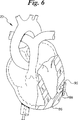
ここで図面を参照する。幾つかの図を通じ、類似の要素は類似の参照符合にて示してある。図1には、動脈22、左心室30、及び心筋層28を有するヒト心臓20が示されている。ガイドカテーテル26内に経皮的心筋血管再生(PMR)カテーテル24が配置され、ガイドカテーテル26は動脈22及び左心室30内に配置されている。PMRカテーテル24は、既に複数の孔すなわち穿通孔32を形成し、これらの孔を血管新生促進物質すなわち脈管形成物質34にて充填し終えた状態にて示されている。好ましい物質としては、血管上皮増殖因子(VEGF)、繊維芽細胞増殖因子(FGF)、及びエストロゲンがある。脈管形成物質34は、時間の経過にしたがって放出されるヒドロゲルのような生分解性物質を担体とすることが好ましい。担体物質は、脈管形成物質を固定し、これを心室内に引き込もうとする力に抗するために接着される。特定の実施形態においては、担体物質としてX線不透過性物質が含まれる。X線不透過性物質により、孔の深さや、引き出された、すなわち洗い流された物質を可視化することが可能である。孔32は、生分解性物質の分解後も開存状態に保つことが可能であり、脈管形成物質によって、孔の壁の近傍における、また心筋層内への血管の成長が促進される。孔32は閉鎖することも可能であり、開存状態の孔はなくなるが新たに形成された血管は残る。発明者等は、脈管形成物質によって新血管の成長が大幅に促進され、左心室の内部から左心室の心筋層への血流が増大するものと考える。新たに成長した血管は、吻合部において他の血管に合流し、左心室から、及び冠状動脈により供給される他の血管から血液供給を受ける心筋層内に血管の大きなネットワークを形成する。
【0011】
図2は、外側シャフト36及び内側シャフト38を有するカテーテルの一実施形態を部分断面図にて概略的に示したものである。内側シャフト38は、開口42を有し、末端側に配置される切開先端部40を好ましくは備える。開口42は末端部40を介して管腔52と流体移動可能に連通している。内側シャフト38は、基端側シャフト部分44及びより高い可撓性を有する末端側シャフト部分46を好ましくは有する。内側シャフト38はモータ48に連結され、回転に対して固定された外側シャフト36に対し、内側シャフト38の中心軸を中心として回転することが可能である。モータ48は電池50として概略的に示された電源に接続される。外側シャフト36と内側シャフト38との間の間隔は、内側シャフト38が外側シャフト36に対して充分な回転を行えるように充分な大きさでなければならない。回転運動は、これにより切開先端部40内の心筋性物質が取り除かれ、大径かつ開存性の孔が形成されるために好ましい。一方法においては、内側シャフト38は外側シャフト36に対して回転せず、大径の孔を心筋に残すことなく脈管形成物質を注入することが可能である。内側シャフト38は外側シャフト36に対して長手方向に摺動可能である。
【0012】
図3は、図2に概略的に示されたPMRカテーテル24の内側シャフト38を部分側断面図にて示したものである。好ましくは皮下針先端である切開先端部40は、内側シャフト38の長手方向の中心軸に対して鋭角の角度をとって末端側に配置される切開エッジ42を有する。先端部40は開口42に対して流体移動可能に連通した管腔52を有する。管腔52及び開口42により、脈管形成物質及び接着剤を先端部40を通じて移送し、先端部40によって形成されたばかりの孔に注入することが可能である。特定の実施形態では、脈管形成物質とともにX線不透過性物質が含まれる。X線不透過性物質により、注入が適正に行われたことの確認、孔の深さの可視化、及び孔から引き出された、すなわち洗い流された任意の物質を可視化することが可能である。先端部40は、好ましくは皮下針にて構成されるが、当業者に知られるような適当な耐久性及び生体適合性を有する他の材料にて構成することも可能である。先端部40は例として0.09144cm(0.036インチ)の外径を有する。
【0013】
基端側シャフト44は末端側シャフト46よりも高い剛性を有するステンレス鋼製下部管にて好ましくは構成される。シャフト44は管腔56を通じて長手方向に延びる。基端側シャフト44は、好ましくは内側シャフト38の全長の大半にわたって延び、内側シャフト38の可推進性及び可捩性が向上する。基端側シャフト44に対しては下部管を用いた構成が好ましいが、シャフト44は後に詳述する末端側シャフト46と同様の構成を有することも可能であり、また当該技術分野において知られる充分な可捻性及び可推進性を有する別の構成を用いることも可能であることは認識されよう。
【0014】
末端側シャフト部分46は好ましくは基端側シャフト44よりも高い可撓性を有し、切開先端部40に隣接する内側シャフト38の可追従性が向上する。末端側シャフト46は、全体を通じて延びる長尺状管腔60を有する螺旋状コイル58にて構成することが可能であり、管腔60は基端側シャフト44の管腔56及び切開先端部40の管腔52に対して流体移動可能に連通する。コイル58はポリマ製シース62により包囲される。シース62はPTFE、収縮包装や当業者に知られる他の類似の生体適合性材料にて形成することが可能である。管腔60の管腔壁を構成する内部コイル58を同様にコーティングすることが可能である。シャフト46はまたニチノールなどの超弾性合金にて形成することも可能である。
【0015】
先端部40及び基端側シャフト44は、2個の短い管状部分64により末端側シャフト46に連結することが可能であり、それぞれ管腔56及び60、及び、管腔56及び52内に挿入することが可能である。管状部分64としては、小径の下部管部分、または、管腔52,56及び60に対して流体移動可能に連通する管腔を有するとともに充分な耐久性かつ生体適合性を有する他の管状要素を用いることが可能である。接着剤、ブレイズ、またはタップを用いて部分64をシャフト44及び46ならびに先端部40に対して取り付けることが可能である。
【0016】
使用に際しては、内部シャフト38の切開先端部40を、カテーテル管により血管を通じて心臓壁及び心筋層に送達することが可能である。一実施形態においては、切開先端部40が心臓壁に接触させられると、モータ48が作動して切開先端部40、ひいてはブレード42を回転させる。切開先端部40を更に心臓の心筋層内に前進させることにより、回転ブレードの径路上の組織が破砕される。破砕された組織は内側シャフト38を通じて延びる管腔52を通じて吸引することが可能である。切開先端部40は回転させることなく心筋層に貫通させることが可能である点は認識されよう。しかし、先端部40を回転させない場合、一般に組織は破砕されない。
【0017】
一般に孔の深さは心臓壁の厚さの1/3〜3/4である。個々の孔の深さは個々の患者に対してケースバイケースで決められる。超音波法を使用して患者の心臓を可視化し、好適な孔の深さを決定することが可能である。一方法においては、X線不透過性物質を孔に注入して孔の深さを決定することが可能である。X線不透過性物質の注入、及びX線透視法などの方法を用いた孔の深さの可視化に続いて孔を切開形成することが可能である。所望の孔の深さが得られるまで切開、X線不透過性物質の注入、及び深さの可視化の一連の動作を繰返すことが可能である。孔の深さは心筋層内への切開先端部40の貫通の深さに一般に比例する。切開先端部40の回転速度は、先端部40が作用する心組織の性質に応じて異なり得るが、切開先端部の進路上の組織が破砕される程度に充分に高速でなければならない。造影剤を増殖因子薬剤に配合、または混合することが可能である。
【0018】
内側シャフト38及び管腔52を使用して、先端部40が固定されている間に脈管形成物質、接着剤、及び他の担体物質を心筋層内に送達することが可能である。好ましい一方法においては、接着剤は先端部から出た後に硬化する。一方法では水分硬化性の接着剤を使用する。心筋層に形成された孔の壁に脈管形成部物質が接着させられることにより、脈管形成物質は心筋層内に留まりやすい。好ましくは、脈管形成物質は接着剤によって、孔から引き出す力に抗するだけの充分な強さで孔の壁に結合させられるが、この際、接着剤は分解または吸収され、接着剤から脈管形成物質が拡散し、心筋層内に吸収されることが可能である。X線透視剤すなわちX線不透過性物質を脈管形成物質と組み合わせて使用することにより、引き出された物質を可視化することが容易となる。
【0019】
図4を参照すると、心筋領域78内に埋設されたPMR管状埋設要素すなわちスパイク66が示されている。管66は生分解性のもの、もしくは永久的なものを用いることが可能である。PMR管すなわちスパイクは幾つかの機序によって動作するものと考えられる。第1に、これらの管を心筋層内に進めることにより血管新生などの治癒応答が引き起こされるものと考えられる。第2に、これらの管により所定の長さの時間にわたって心筋層に脈管形成剤を送達する。これにより治癒応答とは別に、新たな血管の増殖が促進される。増殖因子の送達により、一般に更に治癒応答が速くなり、埋設された管に対する好ましくない応答は最小化される。第3に、管腔及び側孔を有する管により、これらの管を通じて心筋層に血流を与えるための孔が管内に与えられる。
【0020】
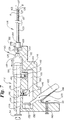
管の好ましい一実施形態では、円形の断面形状、管腔70、側孔74、基端側開口80、及び末端側開口68を有し、基端側開口80、管腔70、側孔74、末端側開口68を通じて、心筋組織への血流が与えられる。管66は以下に詳述する生分解性の高分子材料にて好ましくは形成される。一実施形態では、管状壁は大きな別個の孔を有するものではなく、血液を通過させる多孔性のものが用いられる。別の一実施形態は、管腔を有さず、生分解性材料内に埋設される、時間の経過にともなって放出される増殖因子にて構成され、これにより脈管形成物質が心筋組織内に送達されるとともに管が溶解し、脈管形成物質にて処理される組織によって囲まれる開存性の孔が形成される。管66は心筋層中への挿入を容易とするための切開先端部72を好ましくは有する。管はスパイクの心筋層中への保持を助けるために逆目形成された外表面を有することも可能である。管は、管が既に埋設されている部分をX線透視法により可視化することを助ける手段としてX線不透過性物質を含むことが可能である。これらの管は健康な組織から冬眠中の組織へと所定の規則性にて埋設することが可能であり、冠状動脈及び心室自体から供給される血液の両方を運ぶ新たな血管のネットワークを形成する。
【0021】
管は心室内からカテーテルの管腔を通じて送達される。管はまた、開心術や低侵襲性手術において外部から心筋層中に導入することも可能である。外部から送達される管は、管腔、側孔、血液の損失を最小化するための閉鎖基端、及び、管が心筋から引き出される可能性を低減するための逆目を有する外表面を好ましくは有する。低侵襲性の術式においては、PMR管を長尺のカテーテルを通じて心膜内に導入することが可能である。PMR管は心筋層を通じて全体を進めることが可能であり、またこうした進入の途中で止めることも可能である。発明者等は、外部から挿入されるこうしたPMR管によって、PMR管が心内膜にまで貫通しない場合においても心筋層中の血管新生を大幅に促進することが可能であると考える。
【0022】
図5を参照すると、心筋層内の血管新生を促進するための別の方法が示されている。心臓20は左心室の外側において創傷84を有する。創傷84は心膜から心筋層に至る複数の切創86により構成される。一方法においては、創傷は図5に示されるような楔形の切創ではなく、複数の穿刺として構成される。図6を参照すると、創傷の形成後に脈管形成物質、創傷治癒薬、及び増殖因子を創傷に適用して治癒応答を促進する。増殖因子及び治癒薬を含むことにより、脈管形成の目的は達成されないにせよ、心臓の創傷の治癒を促進することが可能である。更に創傷を覆ってパッチ90を用いることにより、創傷上に脈管形成物質を保持することが可能である。一実施形態では接着剤によりパッチを固定する。
【0023】
パッチ90は、必要がなくなった時点で身体に吸収される生分解性のものであることが好ましい。特定のパッチでは、パッチの内部から滲出する脈管形成物質のための溜り部を有し、時間の経過にしたがって更なる創傷治癒及び脈管形成化合物が供給される。
【0024】
心臓の外側への創傷の形成及びパッチの適用は、こうした術式を行ううえで心臓にアクセスすることが可能な開心術と組み合わせて行うことが可能である。また、低侵襲性の術式によって心臓にアクセスして心臓に外側から創傷を形成し、比較的小さな開口部を通じてパッチを適用することが可能である。出願人は、心臓の外側に創傷を形成することにより、創傷領域への新血管形成を含む治癒応答が心筋層内で引き起こされるものと考える。こうした切創は心室壁の厚さの全体にわたらないことが好ましいが、出願人は心筋層内に切創を形成することによって、心室内からの血管供給を受けるとともに冠状動脈によって供給されることが可能な心筋層内で血管の増殖が引き起こされるものと考える。
【0025】
本発明に基づけば各種の脈管形成物質及び増殖因子の使用が可能である。本発明における使用に適当な増殖因子としては、繊維芽細胞増殖因子(FGF、FGF−1、FGF−2)、血管上皮増殖因子(VEGF−2を含む全てのもの)、及び内皮細胞有糸分裂誘発性増殖因子などが含まれる。エストラジオール(E2)、エストリオール(E3)、及び17−ベータエストラジオールを含むエストロゲンなどの脈管形成性物質もやはり本発明における使用に適当であると考えられる。エストロゲンは脈管形成を誘導し、透過性を増大させるものと考えられる。これにより、血管新生を通じて局所的な血液循環が増大する。心組織への遺伝子導入を行うことも可能である。
【0026】
本発明における使用に適当な生分解性ポリマとしては、ポリ(L−ラクチド)(PLLA)、ポリ(D,L−ラクチド)(PLA)、ポリグリコリド(PGA)、ポリ(L−ラクチド−コ−D.L.ラクチド)(PLLA/PLA)、ポリ(L−ラクチド−コ−グリコリド)(PLA/PGA)、ポリ(炭酸グリコリド−コ−トリメチレン)(PGA/PTMC)、ポリジオキサノン(PDS)、ポリカプロラクトン(PCL)、ポリヒドロキシブチレート(PHBT)、ポリ(ホスファジン)、ポリ(D,L−ラクチド−コ−カプロラクトン)(PLA/PCL)、ポリ(グリコリド−コ−カプロラクトン)(PGA/PCL)、ポリ(ホスファーゼエステル)、及びポリ無水物などが含まれる。増殖因子と混合するうえで適当な他の物質としては、ヒドロゲル、酸化ポリエチレン及びその共重合体、ポリビニルピロリドン、ポリアクリレート、ポリエステル、ゼラチン、コラーゲン、タンパク質、アルギン酸ナトリウム、カラヤガム、グアーガム、寒天、アルギン、カラギーナン、ペクチン、キサンタン、デンプン性ガム、セルロースのヒドロキシアルキル及びエチルエーテル、カルボキシメチルセルロースナトリウム、ポリビニルアルコール、及び親水性ポリウレタンが含まれる。
【0027】
本発明においては、心臓の創傷を覆ってパッチを接着するため、及び創傷中に脈管形成物質を保持するために、各種の接着物質を適当に用いることが可能である。こうした接着物質の1つとしてゼラチン及びポリ(L−グルタミン酸)(PLGA)からなるヒドロゲルがある。このヒドロゲルはゼラチンとポリ(L−グルタミン酸)とを化学的に架橋することにより形成される。他の接着剤としてフィブリン接着物質がある。好適なフィブリン接着物質の1つでは、フィブリノーゲン、トロンビン、塩化カルシウム、及び第VIII因子が含まれる。接着物質の別のファミリーとして、シアノアクリレート類がある。好適なシアノアクリレート類としては、ブチル−2−シアノアクリレート(ヒストアクリル)、エチル−2−シアノアクリレート、及びオクチル−2−シアノアクリレートが含まれる。ゼラチン−レゾルシノールホルムアルデヒド−グルタルアルデヒドは別の好適な接着物質である。
【0028】
出願人は、アミノ基、ジ及びトリジオール基を有するポリウレタン、酢酸ポリビニル、ポリアミド、ポリビニルアルコール、ポリスチレン、ポリラクチド、ポリラクトン、ポリエステル、ポリアミド、及びポリウレタンを含むブロック共重合体、及びこれらの組合わせや混合物などの、適当な接着性を有する多くのポリマの使用も可能であると考えるが、これらに限定されるものではない。
【0029】
増殖因子、脈管形成物質、及び生分解性担体や接着剤を、心室壁の穿孔に対して内側から適用し、心臓の外側の創傷に対して外側から適用し、管やスパイクに組み込んで心筋層内へ埋設することが可能である。
【0030】
図7は、投薬アクチュエータ銃112及びカテーテル114を有するPMRカテーテルアセンブリ110を示す概略図である。銃112は本体116を有する。図7においては概略的に示されているが、本体116の内部には注射器118、摺動体120及びプランジャ124が摺動可能に配置されている。注射器118、摺動体120、及びプランジャ124は、各要素の近くの矢印によって示されるように基端及び末端方向に摺動可能である。トリガ122はピン123を中心として回動可能に本体116に取り付けられている。器械設計の技術分野における当業者であれば、ここに示される概略的な説明に基づいて銃112を容易に製造することが可能であることは理解されよう。
【0031】
カテーテル114は、内側管状シャフト126を有する。内側管状シャフト126は鋭利に形成された末端127を有する。注射器118、摺動体120及びプランジャ124と同様、内側シャフト126は矢印によって示されるように基端及び末端方向に可動である。より詳細には、内側シャフト126は、先端部127がカテーテル114の外側シャフト129内に位置する基端側位置Aから、先端部127が外側シャフト129の末端側に位置する第2の位置Bへと動かすことが可能である。
【0032】
注射器118は、所定量の薬剤または他の流体を入れるための内側空間130を有する。プランジャ124の末端にはプランジャシール132が配される。プランジャシール132を有する注射器118は、銃112内への設置に先立って所定量の薬、物質や他の流体を予め封入していることが好ましい。注射器118は、内部シャフト126を注射器118に流体移動可能に連結するためのルエル嵌合部128または同様の取り付け要素を備える。プランジャ124の基端はハンドル134を有する。ハンドル134を用いてハウジング116内でプランジャ124をプランジャの長手方向の中心軸を中心として回転させることが可能である。プランジャ124はプランジャから突出する複数の歯を有する。注射器118は更にクレードル138を有し、クレードル138内にはバネ142によってプランジャ124の方向に付勢された1方向プランジャロック140が配置される。ロック140は、プランジャ124の歯136が末端側に進むことは可能であるが、プランジャ124が基端側に引き戻されることは防止するように歯136に対して係合する斜面を有する1以上の歯を有する。しかし、プランジャ124は、これをハンドル134によってプランジャの中心軸を中心として回転させ、歯136が例として図7に示されるように下方を向くのではなく上方を向くように、ロック140から遠ざかる方向に向けられる場合には基端側に引き戻すことが可能である。
【0033】
摺動部120は注射器118のクレードル138に対して係合可能な表面を有する注射器規制要素144を備える。摺動部120にはピン148によってプランジャ推進要素146が回動可能に取り付けられている。推進要素146は図7に示されるようにバネ150によって垂直位置に向けて付勢されている。摺動部120がプランジャ124に対して基端側に動くのにしたがって、推進要素148は矢印によって示されるように下方に向けて回動し、摺動部120はプランジャ124に対して基端側に動くことが可能となる。推進要素146は歯136を通過すると回動して垂直位置に復帰し、摺動部120によって垂直位置に保持され、歯136の内の1つの、垂直な基端側の側面に対して係合する。摺動部120は溝152を有する。ピン156がトリガ122の一端を通じて延び、溝152内で摺動可能となっている。トリガ122はバネ158によって図に示される位置に向けて付勢されている。トリガ122は図に示される位置と調節ネジ160との間で矢印によって示される方向にピン123を中心として回動可能である。調節ネジ160はトリガ122に対して係合可能な末端161を有し、トリガ122のピン123を中心とした時計周り方向の回動を制限する。
【0034】
カテーテル114は好ましくはX線不透過性かつ非外傷性のフッド163を末端において有し、マニホルド164を基端において有する。マニホルド164は、内側シャフト126と外側シャフト129との間に区画される管腔を通じてカテーテルに流体を注入する、あるいはカテーテルから流体を取り出すための開口166を有する。マニホルド164は更に、本体116をカテーテル114に連結するための、本体116の一部に係合可能なフランジ168を有する。
【0035】
図8は、注射器118を有するカテーテル114の部分を含むカテーテルアセンブリ110の一部の断面図である。ルエル嵌合部128は、内側シャフト126に連結された適合するルエル嵌合部174の螺刻部172に対して係合可能な螺刻部170を有する。注射器118はポリマまたはゴム製シール176によってシールされる内側シャフト受け管腔175を有する。シール176は、螺刻部162が螺刻部170内に進められる際に内側シャフト126の尖鋭末端167によって穿通される。これにより内側シャフト126を介して管腔と空間130とは流体移動可能に連通する。フランジ168はシール171の一部として構成することが可能である。シール171は内側シャフト126とマニホルド164との間に実質的に液密のシールを与えるが、内側シャフト126は外側シャフト129のマニホルド164の内部において矢印にて示される基端及び末端方向に動くことが可能である。バネ178は内側シャフト126をマニホルド164及び外側シャフト129に対して末端方向に付勢する。内側シャフト126の末端方向への移動は、係止盤180とマニホルド164の係止リング182とが係合することによって制限される。
【0036】
図9は、内側シャフト126及び外側シャフト129を有するカテーテル114の好適な一実施形態を断面図にて示したものである。図9に示されるように外側シャフト129は適当な熱接着剤を使用してマニホルド164に連結される。外側シャフト129は、好ましくは、例として、PEBA製の内側層及び外側層、及びその間に配されるステンレス鋼製強化ブレードを有する共有ブレード要素としての基端側部分184を備える。外側シャフト129は更に、バネコイル188及び外側ポリエチレンシース186を有する末端側部分を好ましくは有する。シース186の末端にはフード163が取り付けられている。フード163は非外傷性材料にて好ましくは形成され、X線透視法による可視性を向上させるためにX線不透過性材料を含むことが可能である。内側管126は、例として熱処理したステンレス鋼にて形成することが可能な基端側部分190、及びニチノール製の下部管にて好ましくは形成される末端側部分192を好ましくは有する。末端側管192の末端には末端側先端部127を有する針194が、X線不透過性であり得るスウェージカラー196によって取り付けられる。スウェージカラー196はフード163に対して係合して外側シャフト129に対する内側シャフト126の末端方向への移動を制限する。
【0037】
当業者によれば、ここに開示される装置を構成するうえで有利に使用することが可能な多くの材料が考えられる点は認識されよう。これらの材料は装置が供される用途を考慮して選択されなければならない。
【0038】
使用時においてはカテーテル114を、図1のカテーテル24と同様、大腿動脈、上腕動脈、または頚動脈を通じて、例として左心室などの心臓の室房内に進めることが可能である。カテーテル114のフード163は、選択された位置において心室の心内膜に対して接触させられる。注射器118の空間130は、好ましくは、例として先に述べたような種類の薬剤や増殖因子にて予め充填される。次にトリガ122が、図7に示される位置から設定ネジ160に向かう方向に時計回りに回動させられる。これにより摺動体122は末端方向に摺動する。トリガ122が図7の位置にあるとき、内側シャフト127の先端部127は外側シャフト129内に引き込まれた位置Aにある。摺動体120が末端側に摺動するにしたがって規制要素144もまた末端方向に進み、バネ178の作用によって注射器118、内側シャフト126、及び先端部127が末端方向に進められ、先端部127はフード163の末端側の位置Bに位置することになる。先端部127が位置Aにあるときには、円盤180はリング182から基端側に離間する。
【0039】
位置Aから位置Bへと先端部127が前進するのとほぼ同時に、プランジャ推進要素146が歯136の内の1個の基端側側面に対して係合してプランジャ136を溜り部130内に末端方向に進め、内側シャフト126及び位置Bにおいて心筋層内に置かれる先端部127を通じて所定量の薬剤または増殖因子を推し進める。投薬量は調節ネジ160によってトリガ122の移動量を制限することにより調節することが可能である。リング182が内側シャフト126及び注射器118の末端方向への移動量を、プランジャ124の末端方向への移動距離よりも小さい距離に制限することにより、プランジャ124が空間130内に相対的に前進して、内側シャフト126を通じて薬剤や増殖因子が推し進められる点は認識されよう。
【0040】
トリガ122は解放されるとバネ158の作用によって反時計回りに回動して図7に示される位置に戻る。トリガ122が反時計回りに回動して元の位置に戻るのにしたがって、プランジャ124及び推進要素146は時計回りに回動して1以上の歯136の基端側傾斜面に対して係合する。注射器118及び内側シャフト126は要素144がクレードル138に対して係合することにより基端方向に摺動する。トリガ122が元の位置に復帰した時点で、再びこれを引いて先端部127を前進させ、更なる薬剤または増殖因子を心筋層に送達することが可能である。
【0041】
図10は、カテーテル114の末端部の別の構成を示す側面図である。この実施形態では、カテーテル114は、フード163と同様、好ましくは非外傷性材料にて形成され、X線透視法による可視性を向上させるためにX線不透過性材料を含むことが可能なフード263を有する。フード263は径のより大きな開口265を有する。フード263の直ぐ基端側には針194に接触してこれを包囲する環状ブラシ198が配される。針194には、X線不透過性物質を添加した適当な金属、または、生体安定性または生分解性の材料にて形成することが可能なX線不透過性マーカバンド200が緩く取り付けられる。図10に示されるように、フード263は心筋層28に接する心内膜に対して押し当てられる。
【0042】
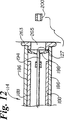
図11では、針194はフード263の末端を越えて末端側に進められており、X線不透過性マーカ200は心筋層128内に置かれている。図12では、針194はカテーテル114内に基端方向に引き戻されているが、マーカ200は心筋層28内に留置されている。
【0043】
マーカ200は、例として、後に行われるPMR処置のための標的部分すなわち外周を定義するといったマッピングの目的で使用することが可能である。マーカ200は、将来的に行われるPMR処置、診断、及び監視のために長期的に使用することも可能である。マーカ200は更に、増殖因子、薬剤、または他の治療薬にてコーティングしたり、含浸することも可能である。
【0044】
図13は、別のマニホルド264及び別の末端側管292を有するカテーテル114の縦断面図である。別の末端側管292はニチノール製下部管にて好ましくは形成される。管292は、使用時における心筋組織による詰まりを低減するランセット先端の形態を有する先端部227を好ましくは有する。実施形態において開示される先端部のそれぞれにランセット端を使用することも可能である。先端部は好ましくは30〜23ゲージのものが用いられるが、より大径または小径のものを使用することも可能である。
【0045】
マニホルド264は、上述のマニホルド164のフランジ168と同じ要領で銃本体116の一部に対して係合させるために使用することが可能なフランジ302を有する。マニホルド262の内部には複数の段差304,305及び306が設けられる。内側シャフト126の基端側部分190の基端付近には、銃116の注射器118のルエル嵌合部128に係合することが可能なルエル嵌合部274の別の実施形態が設けられている。ルエル嵌合部274は螺刻部272を有する。ルエル嵌合部274の末端には段差係合要素300が設けられる。バネ278は、基端がマニホルド274の内部において固定され、末端はルエル嵌合部274に対して固定されている。バネ278はルエル嵌合部274を末端側に引くように付勢されている。
【0046】
図14は図13のマニホルド264の基端を示したものである。段差304,305及び306がマニホルドの内部に見える。図13を参照すると、これらの段差のそれぞれは、手前の段差よりも末端側となるように連続的に配置されていることが理解される。
【0047】
図15は図13のルエル嵌合部274の末端を示したものである。長尺の段差係合要素300が見える。段差係合要素300が、マニホルド264の内径にほぼ等しいがマニホルド264の内径よりも小さい長さを有する場合、段差係合要素300はマニホルド264内で摺動し、カテーテル114の長手方向の中心軸を中心とした段差係合要素300の角度位置に応じて段差304,305または306に対して係合することが理解されよう。マニホルド264内において段差がより末端側に配置されるほど、段差係合要素300は特定の段差に対して係合する以前にマニホルド264内においてより末端側に動くことが可能である。
【0048】
嵌合要素300が末端側に進むほど、内側シャフト126ひいては先端部227がより末端側に進むであろうことは理解されよう。すなわち、マニホルド264及びルエル嵌合部274を使用することにより、先端部227の心臓壁への進入の深さを制御することが可能である。実際、先端部227が心内膜と心外膜との間に置かれるよう、先端部222が心臓壁を完全に貫通するように進入の深さを調整することが考えられる。先端部227がこのような位置におかれる場合では、カテーテル114を使用して、薬剤、増殖因子または他の治療薬もしくは流体を心外膜内に送達することが可能である。
【0049】
内側シャフト126の末端方向への運動は、段差304,305または306やマニホルド264によって、上記にマニホルド164に関連して示した構成によって、あるいは、図9において示したようなフッド163に係合するスウェージ196によって制限することが可能であることは理解されよう。カテーテル114の末端に設けられる係止部により、心筋層内への内側シャフト先端部127の進入の深さをより一貫して制御することが可能である。これは、内側シャフト126の長さを充分に長くして、心房のアクセス径路に沿ったカテーテル114の折れ曲がりとは関係なく、シャフト126が末端側に進められる際にスウェージ196がフード163に対して係合するように構成することによって容易に行うことが可能である。マニホルド264に関連して述べたような可変深さ制御要素をカテーテル114の末端に設けることも可能であることは理解されよう。
【0050】
図16は、本発明に基づくマニホルド350の別の一実施形態を断面図にて示したものである。マニホルド350は外側シャフト129の基端に配置することが可能である。内側シャフト126は外側シャフト129を通じてマニホルド350内に延びる。マニホルド350は、1側面からレバーアーム354が基端方向に延びるハウジング352を好ましくは有する。レバーアーム354は、ハウジング352内に形成される、長手方向に延びる長尺の溝356の近傍に好ましくは設けられる。レバーアーム354は、好ましくは、レバーアーム354と溝356との間の領域358にわたって延びる。レバーアーム354は基端362の末端側に設けられる規制切り欠き360を好ましくは有する。支柱部材364がレバーアーム354の末端362付近から延出する。ハウジング356は当業者に知られるポリマや他の材料にて好ましくは形成される。レバーアーム354を形成する材料は、充分な弾性を有し、溝356に向けて内側に折曲または押し込むことが可能であることが好ましい。
【0051】
ハウジング352内には嵌合部366が摺動可能に配置される。嵌合部366としては螺刻部368を有するルエル嵌合部を用いることが可能である。嵌合部366は矢印にて示される基端及び末端方向に摺動可能である。嵌合部366は、好ましくは末端において内側シャフト126に連結され、内部には内側シャフト126を通じる管腔と流体移動可能に連通する管腔174が好ましくは延びる。キャッチアーム370が末端372に向けて末端方向に延びる。嵌合部366は当業者に知られるポリマや他の材料にて好ましくは形成される。キャッチアーム370を形成する材料は、充分な弾性を有し、アーム370を溝356に向けて内側に押し込むことが可能であることが好ましい。
【0052】
好ましくは螺旋状バネコイル376が内側シャフト126の一部を囲んで配置される。バネ376は基端と末端とを有する。バネ376の基端は嵌合部366の末端に連結され、バネ376の末端はハウジング352から延びる固定要素378に連結される。図16に示されるように、バネ376は嵌合部366を引張ることにより伸長した状態にあり、キャッチアーム370の末端372がレバーアーム354の切り欠き360に係合し、アーム354の支柱部材364がキャッチアーム370の一部に対して係合する。この配置では、嵌合部366はハウジング内で基端側の第1の位置にあり、内側シャフト126の末端127は外側シャフト129内に置かれる。嵌合部366は、レバーアーム354の基端362をキャッチ370の方向に押し込むことにより第1の位置から解放されて基端方向に動くことが可能である。これによりキャッチアーム372の末端は切り欠き360から外れ、バネ376の収縮にともなって嵌合部366が第2の位置に向けて末端方向に動くのにしたがってキャッチアーム370は空間358内に動く。第2の位置では、内側シャフト126の末端127は外側シャフト129のフード163を越える(図9に示される状態)。第2の位置に向けた移動量はスウェージ196がフード163に係合することによって制限される。
【0053】
この文書に開示される発明の多くの特徴及び利点についてここまでの説明文で述べてきた。しかしながらこの開示は多くの意味においてあくまで説明的なものであることは理解されるであろう。特に、形状、大きさ、及び構成要素の配置といった細部において発明の範囲を超えることなく変更を加えることが可能である。発明の範囲は無論のこと特許請求の範囲を述べる文言によって定義されるものである。
【図面の簡単な説明】
【図1】PMRカテーテルが内部に挿入されるとともに、内部から心筋に形成され、血管形成物質によって充填された穿通孔を有するヒトの心臓を示す切り欠き斜視図。
【図2】ガイドカテーテル内に置かれたPMRカテーテルを示す部分断面概略側面図。
【図3】本発明に基づく図3のカテーテルを示す部分断面図。
【図4】内腔及び側孔を有する本発明に基づいたPMRスパイクを示す部分断面図。
【図5】左心室の壁の外側に創傷を有するヒトの心臓を示す切り欠き斜視図。
【図6】脈管形成物質及びパッチを使用した、図5の創傷を有するヒトの心臓を示す切り欠き斜視図、
【図7】本発明に基づくカテーテルアセンブリの断面図。
【図8】図7のカテーテルアセンブリの細部を示す断面図。
【図9】図7のカテーテルアセンブリのカテーテル部分の断面図。
【図10】X線不透過性マーカが内部に置かれたカテーテルの先端部の断面図。
【図11】カテーテル先端部よりも末端側に位置するX線不透過性マーカを示す図10のカテーテル先端部を示す図。
【図12】心筋内に位置するX線不透過性マーカを示す図10のカテーテル先端部を示す図。
【図13】本発明に基づくカテーテルの別の実施形態を示す縦断面図。
【図14】本発明に基づくマニホルドの別の実施形態を基端側より見た図。
【図15】本発明に基づくルエル嵌合部の別の実施形態を末端側より見た図。
【図16】本発明に基づく別のマニホルドの断面図。[0001]
(Related application information)
This application is filed on Nov. 4, 1997, and is entitled “TRANSMYOCARDIAL REVASVULALIZATION FACTOR MEDIUMMS AND METHOD”, US Provisional Patent Application No. 60 / No. 064,210 and US patent application Ser. No. 08 / 812,425 filed Mar. 6, 1997, entitled “TRANSMYOCARDIAL REVASCULALIZATION CATHETER AND METHOD”. Benefit from retroactive application date.
[0002]
(Field of Invention)
This application relates to an apparatus and method for promoting blood circulation to the myocardium. The present invention relates in particular to percutaneous myocardial revascularization (PMR) devices and methods.
(Background of the Invention)
There are many techniques for treating cardiovascular disease, such as cardiovascular bypass, coronary angioplasty, laser angioplasty, and atherectomy. Typically, these techniques are used for bypass and open lesions to restore and increase blood flow to the myocardium. In some patients, it may be difficult to restore blood flow to the myocardium due to too many lesions and too many lesions in the patient's blood vessels. Substitute myocardial revascularization (PMR) has been developed as an alternative to these techniques for bypass formation and lesion removal. PMR is performed by drilling directly into the myocardium of the heart.
[0003]
PMR is partly inspired by the observation that reptiles are primarily supplied with blood that perfuses directly from the ventricle into the myocardium. This is in contrast to the human heart, which is supplied by a coronary artery that receives blood from the aorta. Good results have been shown in some patients treated with PMR. These results are believed to be based in part on blood flowing from the ventricle through the patency hole formed by the PMR to the myocardial tissue. It has been proposed to form appropriate PMR holes by laser ablation, incision by mechanical means, and ablation by radio frequency equipment. Increased blood flow is also believed to be due to the formation of new blood vessels as a healing response to wound formation, specifically in response to newly formed wounds.
[0004]
What is provided is an improved method and apparatus for increasing blood perfusion into myocardial tissue. What is to be provided is a method and apparatus for increasing blood flow over blood flow previously possible with PMR.
[0005]
(Summary of Invention)
The present invention includes an apparatus and method for increasing blood circulation to the myocardium. Circulation can be augmented by patency holes from the heart chamber to the myocardium and by the formation of new blood vessels. New blood vessels are supplied with blood from inside the chamber of the heart, such as the left ventricle, and from existing blood vessels in the surrounding healthy heart tissue. The formation of new blood vessels can be facilitated by a healing response to the wound formed according to the present invention. The formation of new blood vessels is also promoted by angiogenic substances supplied to the myocardium according to the present invention.
[0006]
One group of methods according to the present invention utilizes a shaft, such as a tube or spike, that is preferably delivered from within the heart by a catheter into the myocardium. Preferably, these tubes contain or are coated with angiogenic material that is released over time. These tubes can be biodegradable that are absorbed by the body, and in certain embodiments, the tubes are patencyd within the myocardium surrounded by the absorbed angiogenic material. A hole remains. Other PMR tubes are not biodegradable, but have a lumen extending therethrough, and a side port is provided along the length of the tube to provide access to the myocardium from within the lumen. This non-biodegradable tube can be made of metal, polymer or other biostable material. Preferably, the non-biodegradable tube is coated with or contains an angiogenic material that is released slowly and promotes the formation of new blood vessels along the entire length of the tube. Blood is supplied to the new blood vessel through the side hole of the tube. One method uses PMR spikes that are advanced from outside the heart into the myocardium and can be used in open heart surgery and minimally invasive surgery.
[0007]
In another group of methods according to the present invention, an angiogenic substance is injected into the myocardium. One preferred method is to form a small bore hole or use a catheter in the heart to inject directly into the myocardium with a needle. After forming the hole, a fluid, gel, or adhesive substance containing an angiogenic material is injected into the hole. In one method, as the angiogenic material is absorbed into the myocardium, there remains a patent hole surrounded by myocardial tissue treated with the angiogenic material. In another method, the injection hole is closed, leaving no patency hole. The formation of new blood vessels is facilitated by both the healing response to the wound and the angiogenic material. Blood circulation to the myocardial tissue is augmented by both patency pores, as well as existing coronary vessels and new blood vessels that receive supply from within the heart. In another method, an angiogenic material is injected into the myocardium from outside the heart in combination with open heart surgery or minimally invasive surgery.
[0008]
In yet another group of methods, a wound is formed outside the heart and a patch containing an angiogenic material is applied to the wound. The wound preferably reaches the myocardium. The healing response is promoted by angiogenic substances and promotes the formation of new blood vessels around the wound. Wounds usually do not reach the interior of the ventricles, but newly formed blood vessels reach the interior of the ventricles and, moreover, connect to existing blood vessels in healthy heart tissue. The wound extending from the healthy tissue into the hibernating tissue forms a network of blood vessels from the healthy tissue into the hibernating tissue and supplies blood to the hibernating tissue. In another method, an external patch containing an angiogenic material is applied without creating a significant wound in the heart.
[0009]
Angiogenic materials considered suitable for use in the present invention include vascular epidermal growth factor (VEGF) and fibroblast growth factor (FGF). The growth factor carrier of the present invention includes hydrogels. Adhesives suitable for bonding the present invention include fibrin glue and cyanoacrylate.
[0010]
(Detailed description of the invention)
Reference is now made to the drawings. Throughout the several figures, similar elements are indicated with similar reference signs. In FIG. 1, a human heart 20 having an artery 22, a
[0011]
FIG. 2 schematically illustrates, in partial cross-section, one embodiment of a catheter having an
[0012]
FIG. 3 is a partial cross-sectional view of the
[0013]
The
[0014]
The distal shaft portion 46 is preferably more flexible than the
[0015]
The distal end 40 and the
[0016]
In use, the incision tip 40 of the
[0017]
Generally, the hole depth is 1/3 to 3/4 of the thickness of the heart wall. Individual hole depths are determined on a case-by-case basis for individual patients. Ultrasound methods can be used to visualize the patient's heart and determine the preferred hole depth. In one method, a radiopaque material can be injected into the hole to determine the depth of the hole. Following the injection of radiopaque material and visualization of the hole depth using methods such as fluoroscopy, the hole can be incised. It is possible to repeat the sequence of incision, radiopaque material injection, and depth visualization until the desired hole depth is obtained. The depth of the hole is generally proportional to the depth of penetration of the incision tip 40 into the myocardium. The rotational speed of the incision tip 40 may vary depending on the nature of the cardiac tissue on which the tip 40 acts, but it must be fast enough to disrupt the tissue on the path of the incision tip. It is possible to mix or mix the contrast agent with the growth factor agent.
[0018]
The
[0019]
Referring to FIG. 4, a PMR tubular implantation element or spike 66 embedded in the
[0020]
In a preferred embodiment of the tube, it has a circular cross-sectional shape, a
[0021]
The tube is delivered from the ventricle through the catheter lumen. The tube can also be introduced externally into the myocardium in open heart surgery or minimally invasive surgery. The tube delivered from the outside preferably has a lumen, a side hole, a closed proximal end to minimize blood loss, and an outer surface with a reverse eye to reduce the likelihood that the tube will be drawn from the myocardium Has. In a minimally invasive procedure, the PMR tube can be introduced into the pericardium through a long catheter. The PMR tube can be advanced entirely through the myocardium and can be stopped during such an entry. The inventors think that such an PMR tube inserted from the outside can greatly promote angiogenesis in the myocardium even when the PMR tube does not penetrate into the endocardium.
[0022]
Referring to FIG. 5, another method for promoting angiogenesis within the myocardium is shown. The heart 20 has a wound 84 outside the left ventricle. The wound 84 is composed of a plurality of cuts 86 extending from the pericardium to the myocardium. In one method, the wound is configured as a plurality of punctures rather than a wedge-shaped cut as shown in FIG. Referring to FIG. 6, angiogenic substances, wound healing agents, and growth factors are applied to the wound after wound formation to promote the healing response. By including growth factors and healing agents, it is possible to promote the healing of heart wounds even if the purpose of angiogenesis is not achieved. Furthermore, by using the
[0023]
The
[0024]
The formation of wounds and the application of patches on the outside of the heart can be performed in combination with open heart surgery that allows access to the heart to perform these procedures. It is also possible to access the heart with a minimally invasive procedure to form a wound in the heart from the outside and apply the patch through a relatively small opening. Applicants believe that forming a wound outside the heart causes a healing response in the myocardium, including neovascularization to the wound area. Such incisions preferably do not cover the entire thickness of the ventricular wall, but applicants receive vascular supply from the ventricle and are supplied by coronary arteries by forming a cut in the myocardium. It is thought that the growth of blood vessels is caused in the myocardium where it is possible.
[0025]
Based on the present invention, various angiogenic substances and growth factors can be used. Suitable growth factors for use in the present invention include fibroblast growth factors (FGF, FGF-1, FGF-2), vascular epidermal growth factors (all including VEGF-2), and endothelial cell mitosis. Inducible growth factors are included. Angiogenic substances such as estrogens including estradiol (E2), estriol (E3), and 17-beta estradiol are also considered suitable for use in the present invention. Estrogens are thought to induce angiogenesis and increase permeability. This increases local blood circulation through angiogenesis. It is also possible to introduce genes into heart tissue.
[0026]
Biodegradable polymers suitable for use in the present invention include poly (L-lactide) (PLLA), poly (D, L-lactide) (PLA), polyglycolide (PGA), poly (L-lactide-co-). DL lactide) (PLLA / PLA), poly (L-lactide-co-glycolide) (PLA / PGA), poly (glycolide carbonate-co-trimethylene) (PGA / PTMC), polydioxanone (PDS), polycaprolactone (PCL), polyhydroxybutyrate (PHBT), poly (phosphadine), poly (D, L-lactide-co-caprolactone) (PLA / PCL), poly (glycolide-co-caprolactone) (PGA / PCL), poly (Phosphatase ester), and polyanhydrides. Other materials suitable for mixing with growth factors include hydrogels, oxidized polyethylene and copolymers thereof, polyvinylpyrrolidone, polyacrylates, polyesters, gelatin, collagen, proteins, sodium alginate, karaya gum, guar gum, agar, algin, Carrageenan, pectin, xanthan, starchy gum, hydroxyalkyl and ethyl ether of cellulose, sodium carboxymethylcellulose, polyvinyl alcohol, and hydrophilic polyurethane.
[0027]
In the present invention, various adhesive materials can be suitably used to adhere the patch over the heart wound and to retain the angiogenic material in the wound. One such adhesive material is a hydrogel composed of gelatin and poly (L-glutamic acid) (PLGA). This hydrogel is formed by chemically cross-linking gelatin and poly (L-glutamic acid). Another adhesive is fibrin adhesive. One suitable fibrin adhesive includes fibrinogen, thrombin, calcium chloride, and factor VIII. Another family of adhesive materials is cyanoacrylates. Suitable cyanoacrylates include butyl-2-cyanoacrylate (histacryl), ethyl-2-cyanoacrylate, and octyl-2-cyanoacrylate. Gelatin-resorcinol formaldehyde-glutaraldehyde is another suitable adhesive material.
[0028]
Applicants are responsible for polyurethanes having amino groups, di- and tridiol groups, polyvinyl acetate, polyamides, polyvinyl alcohol, polystyrene, polylactides, polylactones, polyesters, polyamides, block copolymers including polyurethanes, combinations and mixtures thereof, etc. However, it is considered that many polymers having appropriate adhesiveness can be used, but the present invention is not limited thereto.
[0029]
Growth factors, angiogenic substances, and biodegradable carriers and adhesives are applied from the inside to perforation of the ventricular wall, applied from the outside to wounds outside the heart, and incorporated into tubes and spikes to the myocardium It is possible to embed in the layer.
[0030]
FIG. 7 is a schematic diagram illustrating a
[0031]
[0032]
The
[0033]
The
[0034]
[0035]
FIG. 8 is a cross-sectional view of a portion of the
[0036]
FIG. 9 shows a preferred embodiment of a
[0037]
Those skilled in the art will recognize that many materials are possible that can be advantageously used in constructing the devices disclosed herein. These materials must be selected considering the application for which the device is to be served.
[0038]
In use, the
[0039]
At substantially the same time as the
[0040]
When the
[0041]
FIG. 10 is a side view showing another configuration of the distal end portion of the
[0042]
In FIG. 11, the
[0043]
The
[0044]
FIG. 13 is a longitudinal cross-sectional view of a
[0045]
[0046]
FIG. 14 shows the proximal end of the
[0047]
FIG. 15 shows the end of the luer
[0048]
It will be appreciated that the more the
[0049]
The distal movement of the
[0050]
FIG. 16 is a cross-sectional view of another embodiment of a manifold 350 according to the present invention. The manifold 350 can be disposed at the proximal end of the
[0051]
A fitting portion 366 is slidably disposed in the
[0052]
A
[0053]
Many features and advantages of the invention disclosed in this document have been described above. However, it will be understood that this disclosure is illustrative in many ways. In particular, changes in details such as shape, size, and arrangement of components can be made without exceeding the scope of the invention. The scope of the invention is, of course, defined by the language describing the claims.
[Brief description of the drawings]
FIG. 1 is a cutaway perspective view showing a human heart having a penetration hole formed in the myocardium from the inside and filled with an angiogenic substance while the PMR catheter is inserted therein.
FIG. 2 is a partial cross-sectional schematic side view showing a PMR catheter placed in a guide catheter.
3 is a partial cross-sectional view showing the catheter of FIG. 3 in accordance with the present invention.
FIG. 4 is a partial cross-sectional view showing a PMR spike according to the present invention having a lumen and side holes.
FIG. 5 is a cut-away perspective view of a human heart having a wound on the outside of the left ventricular wall.
6 is a cutaway perspective view of the human heart having the wound of FIG. 5 using an angiogenic material and a patch;
FIG. 7 is a cross-sectional view of a catheter assembly according to the present invention.
8 is a cross-sectional view showing details of the catheter assembly of FIG.
9 is a cross-sectional view of the catheter portion of the catheter assembly of FIG.
FIG. 10 is a cross-sectional view of a distal end portion of a catheter in which a radiopaque marker is placed.
11 is a view showing the catheter distal end portion of FIG. 10 showing an X-ray impermeable marker located on the distal side of the catheter distal end portion.
12 shows the catheter tip of FIG. 10 showing a radiopaque marker located within the myocardium.
FIG. 13 is a longitudinal sectional view showing another embodiment of the catheter according to the present invention.
FIG. 14 is a view of another embodiment of the manifold according to the present invention as viewed from the proximal side.
FIG. 15 is a view of another embodiment of the luer fitting portion according to the present invention as seen from the end side.
FIG. 16 is a cross-sectional view of another manifold according to the present invention.
Claims (10)
管腔を含み、かつ先端部を有する長尺状のカテーテルと、
前記カテーテルの管腔内に配置されるスパイクの形態である埋設要素と、を含み、
前記埋設要素の長さは同埋設要素が心内膜から心筋層内へ貫通し、かつ該心筋層内に孔を形成するうえで充分な長さであり、
前記埋設要素は管腔を有し、かつ
前記埋設要素は、血管新生促進材料を含むこと、を特徴とする装置。An apparatus for increasing myocardial blood perfusion, the apparatus comprising:
An elongate catheter including a lumen and having a distal end;
An embedded element that is in the form of a spike disposed within the lumen of the catheter;
The length of the embedded element is sufficient for the embedded element to penetrate from the endocardium into the myocardium and to form a hole in the myocardium,
The device wherein the implantable element has a lumen and the implantable element includes an angiogenesis promoting material.
Applications Claiming Priority (5)
| Application Number | Priority Date | Filing Date | Title |
|---|---|---|---|
| US6421097P | 1997-11-04 | 1997-11-04 | |
| US60/064,210 | 1997-11-04 | ||
| US09/184,220 US6045565A (en) | 1997-11-04 | 1998-11-02 | Percutaneous myocardial revascularization growth factor mediums and method |
| US184,220 | 1998-11-02 | ||
| PCT/US1998/023396 WO1999022655A1 (en) | 1997-11-04 | 1998-11-03 | Percutaneous myocardial revascularization growth factor mediums and method |
Publications (3)
| Publication Number | Publication Date |
|---|---|
| JP2003521945A JP2003521945A (en) | 2003-07-22 |
| JP2003521945A5 JP2003521945A5 (en) | 2006-01-05 |
| JP4282898B2 true JP4282898B2 (en) | 2009-06-24 |
Family
ID=26744273
Family Applications (1)
| Application Number | Title | Priority Date | Filing Date |
|---|---|---|---|
| JP2000518598A Expired - Fee Related JP4282898B2 (en) | 1997-11-04 | 1998-11-03 | Device for increasing myocardial blood perfusion |
Country Status (6)
| Country | Link |
|---|---|
| US (2) | US6045565A (en) |
| EP (1) | EP1028661A4 (en) |
| JP (1) | JP4282898B2 (en) |
| CA (1) | CA2307102A1 (en) |
| DE (1) | DE1028661T1 (en) |
| WO (1) | WO1999022655A1 (en) |
Families Citing this family (161)
| Publication number | Priority date | Publication date | Assignee | Title |
|---|---|---|---|---|
| US6322548B1 (en) | 1995-05-10 | 2001-11-27 | Eclipse Surgical Technologies | Delivery catheter system for heart chamber |
| US6258083B1 (en) | 1996-03-29 | 2001-07-10 | Eclipse Surgical Technologies, Inc. | Viewing surgical scope for minimally invasive procedures |
| US6152918A (en) * | 1996-04-05 | 2000-11-28 | Eclipse Surgical Technologies, Inc. | Laser device with auto-piercing tip for myocardial revascularization procedures |
| US5755682A (en) * | 1996-08-13 | 1998-05-26 | Heartstent Corporation | Method and apparatus for performing coronary artery bypass surgery |
| US6051008A (en) | 1996-12-02 | 2000-04-18 | Angiotrax, Inc. | Apparatus having stabilization members for percutaneously performing surgery and methods of use |
| US6102926A (en) | 1996-12-02 | 2000-08-15 | Angiotrax, Inc. | Apparatus for percutaneously performing myocardial revascularization having means for sensing tissue parameters and methods of use |
| US6120520A (en) | 1997-05-27 | 2000-09-19 | Angiotrax, Inc. | Apparatus and methods for stimulating revascularization and/or tissue growth |
| US6045565A (en) | 1997-11-04 | 2000-04-04 | Scimed Life Systems, Inc. | Percutaneous myocardial revascularization growth factor mediums and method |
| US6416510B1 (en) * | 1997-03-13 | 2002-07-09 | Biocardia, Inc. | Drug delivery catheters that attach to tissue and methods for their use |
| US5866561A (en) * | 1997-08-21 | 1999-02-02 | Scimed Life Systems, Inc. | Local delivery of estrogen for angiogenesis |
| US6179809B1 (en) | 1997-09-24 | 2001-01-30 | Eclipse Surgical Technologies, Inc. | Drug delivery catheter with tip alignment |
| US5980548A (en) | 1997-10-29 | 1999-11-09 | Kensey Nash Corporation | Transmyocardial revascularization system |
| US6749617B1 (en) * | 1997-11-04 | 2004-06-15 | Scimed Life Systems, Inc. | Catheter and implants for the delivery of therapeutic agents to tissues |
| US6056743A (en) | 1997-11-04 | 2000-05-02 | Scimed Life Systems, Inc. | Percutaneous myocardial revascularization device and method |
| US6251418B1 (en) * | 1997-12-18 | 2001-06-26 | C.R. Bard, Inc. | Systems and methods for local delivery of an agent |
| DE69838526T2 (en) | 1998-02-05 | 2008-07-03 | Biosense Webster, Inc., Diamond Bar | Device for releasing a drug in the heart |
| US6623473B1 (en) | 1998-06-04 | 2003-09-23 | Biosense Webster, Inc. | Injection catheter with multi-directional delivery injection needle |
| US7416547B2 (en) | 1999-03-29 | 2008-08-26 | Biosense Webster Inc. | Injection catheter |
| CA2273467C (en) * | 1998-06-04 | 2009-02-17 | Cordis Webster, Inc. | Catheter for injecting therapeutic and diagnostic agents |
| US6540725B1 (en) | 1998-06-04 | 2003-04-01 | Biosense Webster, Inc. | Injection catheter with controllably extendable injection needle |
| US8079982B1 (en) | 1998-06-04 | 2011-12-20 | Biosense Webster, Inc. | Injection catheter with needle electrode |
| US7252818B2 (en) * | 1998-07-24 | 2007-08-07 | Cardiovascular Biotherapeutics, Inc. | Method of producing biologically active human acidic fibroblast growth factor and its use in promoting angiogenesis |
| US6406488B1 (en) * | 1998-08-27 | 2002-06-18 | Heartstent Corporation | Healing transmyocardial implant |
| EP1112043B1 (en) * | 1998-09-10 | 2006-04-05 | Percardia, Inc. | Tmr shunt |
| US6196230B1 (en) * | 1998-09-10 | 2001-03-06 | Percardia, Inc. | Stent delivery system and method of use |
| US6641610B2 (en) * | 1998-09-10 | 2003-11-04 | Percardia, Inc. | Valve designs for left ventricular conduits |
| US6254564B1 (en) | 1998-09-10 | 2001-07-03 | Percardia, Inc. | Left ventricular conduit with blood vessel graft |
| US6290728B1 (en) | 1998-09-10 | 2001-09-18 | Percardia, Inc. | Designs for left ventricular conduit |
| US6689121B1 (en) | 1998-09-24 | 2004-02-10 | C. R. Bard, Inc. | Systems and methods for treating ischemia |
| US6432126B1 (en) | 1998-09-30 | 2002-08-13 | C.R. Bard, Inc. | Flexible vascular inducing implants |
| US6248112B1 (en) | 1998-09-30 | 2001-06-19 | C. R. Bard, Inc. | Implant delivery system |
| US6458092B1 (en) | 1998-09-30 | 2002-10-01 | C. R. Bard, Inc. | Vascular inducing implants |
| US6251079B1 (en) | 1998-09-30 | 2001-06-26 | C. R. Bard, Inc. | Transthoracic drug delivery device |
| US6692520B1 (en) | 1998-12-15 | 2004-02-17 | C. R. Bard, Inc. | Systems and methods for imbedded intramuscular implants |
| US6620170B1 (en) | 1999-04-26 | 2003-09-16 | C. R. Bard, Inc. | Devices and methods for treating ischemia by creating a fibrin plug |
| US6409697B2 (en) | 1999-05-04 | 2002-06-25 | Heartstent Corporation | Transmyocardial implant with forward flow bias |
| US6719805B1 (en) * | 1999-06-09 | 2004-04-13 | C. R. Bard, Inc. | Devices and methods for treating tissue |
| US6277082B1 (en) | 1999-07-22 | 2001-08-21 | C. R. Bard, Inc. | Ischemia detection system |
| US6629987B1 (en) * | 1999-07-30 | 2003-10-07 | C. R. Bard, Inc. | Catheter positioning systems |
| US6253768B1 (en) | 1999-08-04 | 2001-07-03 | Percardia, Inc. | Vascular graft bypass |
| US6638237B1 (en) | 1999-08-04 | 2003-10-28 | Percardia, Inc. | Left ventricular conduits and methods for delivery |
| US6302892B1 (en) | 1999-08-04 | 2001-10-16 | Percardia, Inc. | Blood flow conduit delivery system and method of use |
| EP1207812A4 (en) * | 1999-08-04 | 2007-06-20 | Bard Inc C R | Implant and agent delivery device |
| US6709427B1 (en) | 1999-08-05 | 2004-03-23 | Kensey Nash Corporation | Systems and methods for delivering agents into targeted tissue of a living being |
| CA2378250A1 (en) * | 1999-08-05 | 2001-02-15 | Todd K. Rosengart | Gene therapy platformed needle and method of administering a therapeutic solution to a heart |
| US6551338B1 (en) | 1999-09-01 | 2003-04-22 | Mcgill University | Method and device for myogenesis and angiogenesis of the heart |
| US6605053B1 (en) | 1999-09-10 | 2003-08-12 | Percardia, Inc. | Conduit designs and related methods for optimal flow control |
| US6663606B1 (en) | 1999-10-28 | 2003-12-16 | Scimed Life Systems, Inc. | Biocompatible medical devices |
| US6800073B2 (en) | 1999-10-28 | 2004-10-05 | Scimed Life Systems, Inc. | Biocompatible pharmaceutical articles |
| US8808272B2 (en) | 1999-10-28 | 2014-08-19 | Boston Scientific Scimed, Inc. | Biocompatible medical devices |
| EP1099453B1 (en) * | 1999-11-12 | 2005-06-01 | Biosense Webster, Inc. | Injection catheter |
| US6854467B2 (en) * | 2000-05-04 | 2005-02-15 | Percardia, Inc. | Methods and devices for delivering a ventricular stent |
| US6613025B1 (en) | 2000-05-25 | 2003-09-02 | Scimed Life Systems, Inc. | Method and apparatus for diagnostic and therapeutic agent delivery |
| DE60134982D1 (en) * | 2000-07-13 | 2008-09-04 | Abbott Cardiovascular Systems | INTRODUCTION SYSTEM FOR MYOCARDIAL, CELLULAR MATERIAL |
| US20020032478A1 (en) * | 2000-08-07 | 2002-03-14 | Percardia, Inc. | Myocardial stents and related methods of providing direct blood flow from a heart chamber to a coronary vessel |
| US6893421B1 (en) | 2000-08-08 | 2005-05-17 | Scimed Life Systems, Inc. | Catheter shaft assembly |
| US6613017B1 (en) | 2000-08-08 | 2003-09-02 | Scimed Life Systems, Inc. | Controlled depth injection device and method |
| US6595958B1 (en) | 2000-08-08 | 2003-07-22 | Scimed Life Systems, Inc. | Tortuous path injection device and method |
| US6582400B1 (en) * | 2000-10-24 | 2003-06-24 | Scimed Life Systems, Inc. | Variable tip catheter |
| US6530914B1 (en) | 2000-10-24 | 2003-03-11 | Scimed Life Systems, Inc. | Deflectable tip guide in guide system |
| WO2003008005A2 (en) * | 2000-11-08 | 2003-01-30 | Boston Scientific Limited | Catheter and implants for the delivery of therapeutic agents to tissues |
| US6616626B2 (en) | 2000-12-21 | 2003-09-09 | Scimed Life Systems, Inc. | Infusion devices and method |
| JP2005501802A (en) * | 2001-01-23 | 2005-01-20 | ボストン サイエンティフィック コーポレイション | Localized myocardial injection method for treating ischemic myocardium |
| US6976990B2 (en) * | 2001-01-25 | 2005-12-20 | Percardia, Inc. | Intravascular ventriculocoronary bypass via a septal passageway |
| US6740040B1 (en) * | 2001-01-30 | 2004-05-25 | Advanced Cardiovascular Systems, Inc. | Ultrasound energy driven intraventricular catheter to treat ischemia |
| US6887857B2 (en) | 2001-04-27 | 2005-05-03 | Scimed Life Systems, Inc. | Microparticle protection of therapeutic agents |
| US7455657B2 (en) | 2001-06-19 | 2008-11-25 | Boston Scientific Scimed, Inc | Method and apparatus to modify a fluid using a selectively permeable membrane |
| US6702744B2 (en) * | 2001-06-20 | 2004-03-09 | Advanced Cardiovascular Systems, Inc. | Agents that stimulate therapeutic angiogenesis and techniques and devices that enable their delivery |
| US6623733B1 (en) | 2001-06-27 | 2003-09-23 | Advanced Cardiovascular Systems, Inc. | Methods for treatment of vascular disease and device for preparation of an autologous composition for treating vascular disease |
| US6592608B2 (en) * | 2001-12-07 | 2003-07-15 | Biopsy Sciences, Llc | Bioabsorbable sealant |
| US6726714B2 (en) * | 2001-08-09 | 2004-04-27 | Scimed Life Systems, Inc. | Stent delivery system |
| US20030036698A1 (en) * | 2001-08-16 | 2003-02-20 | Robert Kohler | Interventional diagnostic catheter and a method for using a catheter to access artificial cardiac shunts |
| US20030060842A1 (en) * | 2001-09-27 | 2003-03-27 | Yem Chin | Method and apparatus for measuring and controlling blade depth of a tissue cutting apparatus in an endoscopic catheter |
| US6893431B2 (en) * | 2001-10-15 | 2005-05-17 | Scimed Life Systems, Inc. | Medical device for delivering patches |
| US8608661B1 (en) | 2001-11-30 | 2013-12-17 | Advanced Cardiovascular Systems, Inc. | Method for intravascular delivery of a treatment agent beyond a blood vessel wall |
| US6955657B1 (en) * | 2001-12-31 | 2005-10-18 | Advanced Cardiovascular Systems, Inc. | Intra-ventricular substance delivery catheter system |
| US6949118B2 (en) * | 2002-01-16 | 2005-09-27 | Percardia, Inc. | Encased implant and methods |
| US7008397B2 (en) * | 2002-02-13 | 2006-03-07 | Percardia, Inc. | Cardiac implant and methods |
| US7169127B2 (en) * | 2002-02-21 | 2007-01-30 | Boston Scientific Scimed, Inc. | Pressure apron direct injection catheter |
| US7218962B2 (en) * | 2002-03-29 | 2007-05-15 | Boston Scientific Scimed, Inc. | Magnetically enhanced injection catheter |
| US7108685B2 (en) | 2002-04-15 | 2006-09-19 | Boston Scientific Scimed, Inc. | Patch stabilization of rods for treatment of cardiac muscle |
| AU2003239418B2 (en) * | 2002-05-08 | 2008-01-31 | The Regents Of The University Of California | System and method for forming a non-ablative cardiac conduction block |
| US7033345B2 (en) * | 2002-05-21 | 2006-04-25 | Advanced Cardiovascular Systems, Inc. | Deflectable microimplant delivery system |
| US20030220661A1 (en) * | 2002-05-21 | 2003-11-27 | Heartstent Corporation | Transmyocardial implant delivery system |
| US7361368B2 (en) | 2002-06-28 | 2008-04-22 | Advanced Cardiovascular Systems, Inc. | Device and method for combining a treatment agent and a gel |
| US20040044329A1 (en) * | 2002-08-29 | 2004-03-04 | Trudell Leonard A. | Catheter for cardiac injection and method for delivery of therapeutic agents to specified tissues |
| US7326219B2 (en) | 2002-09-09 | 2008-02-05 | Wilk Patent Development | Device for placing transmyocardial implant |
| JP2004246317A (en) * | 2002-12-20 | 2004-09-02 | Hitachi Ltd | Cold cathode type flat panel display |
| US20040147868A1 (en) * | 2003-01-27 | 2004-07-29 | Earl Bardsley | Myocardial implant with collar |
| US7393339B2 (en) | 2003-02-21 | 2008-07-01 | C. R. Bard, Inc. | Multi-lumen catheter with separate distal tips |
| US20040191215A1 (en) * | 2003-03-25 | 2004-09-30 | Michael Froix | Compositions for induction of a therapeutic response |
| US20040254518A1 (en) * | 2003-03-27 | 2004-12-16 | Sun Lee | Device to promote blood flow into the myocardium |
| US8821473B2 (en) | 2003-04-15 | 2014-09-02 | Abbott Cardiovascular Systems Inc. | Methods and compositions to treat myocardial conditions |
| US8383158B2 (en) * | 2003-04-15 | 2013-02-26 | Abbott Cardiovascular Systems Inc. | Methods and compositions to treat myocardial conditions |
| US8038991B1 (en) | 2003-04-15 | 2011-10-18 | Abbott Cardiovascular Systems Inc. | High-viscosity hyaluronic acid compositions to treat myocardial conditions |
| US20040243095A1 (en) | 2003-05-27 | 2004-12-02 | Shekhar Nimkar | Methods and apparatus for inserting multi-lumen spit-tip catheters into a blood vessel |
| US8308708B2 (en) * | 2003-07-15 | 2012-11-13 | Abbott Cardiovascular Systems Inc. | Deployment system for myocardial cellular material |
| US7396351B2 (en) | 2003-11-05 | 2008-07-08 | Boston Scientific Scimed, Inc. | Device and method for the delivery of viscous fluids in the body |
| US7678077B2 (en) * | 2004-02-20 | 2010-03-16 | Boston Scientific Scimed, Inc. | Variable depth injection device and method |
| JP4903689B2 (en) * | 2004-04-08 | 2012-03-28 | サンガモ バイオサイエンシズ インコーポレイテッド | Methods and compositions for treating neuropathy and neurodegenerative symptoms |
| CA2561565C (en) * | 2004-04-08 | 2013-11-26 | Sangamo Biosciences, Inc. | Methods for repression of phospholamban gene and modulating cardiac contractility |
| US20070269477A1 (en) * | 2004-05-05 | 2007-11-22 | Igo Stephen R | Heart Treatment Method |
| US8992454B2 (en) * | 2004-06-09 | 2015-03-31 | Bard Access Systems, Inc. | Splitable tip catheter with bioresorbable adhesive |
| US7470252B2 (en) * | 2004-09-16 | 2008-12-30 | Boston Scientific Scimed, Inc. | Expandable multi-port therapeutic delivery system |
| US7854944B2 (en) | 2004-12-17 | 2010-12-21 | Advanced Cardiovascular Systems, Inc. | Tissue regeneration |
| DE102005003632A1 (en) | 2005-01-20 | 2006-08-17 | Fraunhofer-Gesellschaft zur Förderung der angewandten Forschung e.V. | Catheter for the transvascular implantation of heart valve prostheses |
| US7442187B2 (en) * | 2005-01-27 | 2008-10-28 | Boston Scientific Scimed, Inc. | Multiple needle injection catheter |
| US7972295B2 (en) * | 2005-03-11 | 2011-07-05 | Boston Scientific Scimed, Inc. | Apparatus and methods for delivering a bolus of therapeutic material |
| US8828433B2 (en) | 2005-04-19 | 2014-09-09 | Advanced Cardiovascular Systems, Inc. | Hydrogel bioscaffoldings and biomedical device coatings |
| US8303972B2 (en) * | 2005-04-19 | 2012-11-06 | Advanced Cardiovascular Systems, Inc. | Hydrogel bioscaffoldings and biomedical device coatings |
| US20080125745A1 (en) | 2005-04-19 | 2008-05-29 | Shubhayu Basu | Methods and compositions for treating post-cardial infarction damage |
| US8187621B2 (en) | 2005-04-19 | 2012-05-29 | Advanced Cardiovascular Systems, Inc. | Methods and compositions for treating post-myocardial infarction damage |
| US9539410B2 (en) | 2005-04-19 | 2017-01-10 | Abbott Cardiovascular Systems Inc. | Methods and compositions for treating post-cardial infarction damage |
| US20060253068A1 (en) * | 2005-04-20 | 2006-11-09 | Van Bilsen Paul | Use of biocompatible in-situ matrices for delivery of therapeutic cells to the heart |
| US8215957B2 (en) * | 2005-05-12 | 2012-07-10 | Robert Shelton | Dental implant placement locator and method of use |
| JP2009509677A (en) * | 2005-09-30 | 2009-03-12 | Tti・エルビュー株式会社 | Iontophoretic delivery of vesicle encapsulated active substances |
| US20070093789A1 (en) * | 2005-09-30 | 2007-04-26 | Transcutaneous Technologies Inc. | Iontophoresis apparatus and method for delivery of angiogenic factors to enhance healing of injured tissue |
| US20080125634A1 (en) * | 2006-06-14 | 2008-05-29 | Cornova, Inc. | Method and apparatus for identifying and treating myocardial infarction |
| US7732190B2 (en) * | 2006-07-31 | 2010-06-08 | Advanced Cardiovascular Systems, Inc. | Modified two-component gelation systems, methods of use and methods of manufacture |
| US9242005B1 (en) | 2006-08-21 | 2016-01-26 | Abbott Cardiovascular Systems Inc. | Pro-healing agent formulation compositions, methods and treatments |
| US9375313B2 (en) * | 2006-09-08 | 2016-06-28 | The Regents Of The University Of California | Intramyocardial patterning for global cardiac resizing and reshaping |
| US20080065049A1 (en) * | 2006-09-12 | 2008-03-13 | Boston Scientific Scimed, Inc. | Variable stiffness direct injection system |
| US20080167592A1 (en) * | 2006-10-26 | 2008-07-10 | Greer Steven E | Preventing or treating wounds with a collodion barrier incorporating active agents |
| US8741326B2 (en) * | 2006-11-17 | 2014-06-03 | Abbott Cardiovascular Systems Inc. | Modified two-component gelation systems, methods of use and methods of manufacture |
| US9005672B2 (en) | 2006-11-17 | 2015-04-14 | Abbott Cardiovascular Systems Inc. | Methods of modifying myocardial infarction expansion |
| US8192760B2 (en) * | 2006-12-04 | 2012-06-05 | Abbott Cardiovascular Systems Inc. | Methods and compositions for treating tissue using silk proteins |
| WO2008101003A1 (en) * | 2007-02-13 | 2008-08-21 | Cornova, Inc. | Biocompatible polymers, polymer tie-coats, methods of making and using the same, and products incorporating the polymers |
| CA2682160C (en) * | 2007-04-11 | 2017-04-04 | Henry Ford Health System | Cardiac repair, resizing and reshaping using the venous system of the heart |
| US7896915B2 (en) | 2007-04-13 | 2011-03-01 | Jenavalve Technology, Inc. | Medical device for treating a heart valve insufficiency |
| WO2008154033A2 (en) * | 2007-06-11 | 2008-12-18 | Symphony Medical, Inc. | Cardiac patterning for improving diastolic function |
| US8086324B1 (en) * | 2007-09-27 | 2011-12-27 | Pacesetter, Inc. | Intrapericardial lead with distal region configured to optimize lead extraction |
| EP2211965A4 (en) * | 2007-10-17 | 2012-03-14 | Bard Access Systems Inc | Catheters with enlarged arterial lumens |
| WO2009051967A1 (en) * | 2007-10-17 | 2009-04-23 | Spire Corporation | Manufacture of split tip catheters |
| US8500697B2 (en) * | 2007-10-19 | 2013-08-06 | Pressure Products Medical Supplies, Inc. | Transseptal guidewire |
| US8292841B2 (en) | 2007-10-26 | 2012-10-23 | C. R. Bard, Inc. | Solid-body catheter including lateral distal openings |
| US8066660B2 (en) | 2007-10-26 | 2011-11-29 | C. R. Bard, Inc. | Split-tip catheter including lateral distal openings |
| WO2009059220A1 (en) | 2007-11-01 | 2009-05-07 | C.R. Bard, Inc. | Catheter assembly including triple lumen tip |
| US9579485B2 (en) | 2007-11-01 | 2017-02-28 | C. R. Bard, Inc. | Catheter assembly including a multi-lumen configuration |
| US7962223B2 (en) * | 2007-11-16 | 2011-06-14 | Boston Scientific Scimed, Inc. | Ablation probe for drug release in tissue ablation procedures |
| US7963947B2 (en) * | 2008-01-16 | 2011-06-21 | Pressure Products Medical Supplies, Inc. | Apparatus, system, and method of shielding the sharp tip of a transseptal guidewire |
| WO2009102347A1 (en) * | 2008-02-15 | 2009-08-20 | Spire Corporation | Manufacture of fixed tip catheters |
| US20090209940A1 (en) * | 2008-02-15 | 2009-08-20 | Spire Corporation | Fusion manufacture of multi-lumen catheters |
| ES2903231T3 (en) | 2008-02-26 | 2022-03-31 | Jenavalve Tech Inc | Stent for positioning and anchoring a valve prosthesis at an implantation site in a patient's heart |
| US9044318B2 (en) | 2008-02-26 | 2015-06-02 | Jenavalve Technology Gmbh | Stent for the positioning and anchoring of a valvular prosthesis |
| US8801665B2 (en) * | 2008-04-10 | 2014-08-12 | Henry Ford Health System | Apparatus and method for controlled depth of injection into myocardial tissue |
| US20100069760A1 (en) * | 2008-09-17 | 2010-03-18 | Cornova, Inc. | Methods and apparatus for analyzing and locally treating a body lumen |
| US20100160772A1 (en) * | 2008-12-18 | 2010-06-24 | Medtronic, Inc. | Adaptable Image Guided Delivery System |
| CN103002833B (en) | 2010-05-25 | 2016-05-11 | 耶拿阀门科技公司 | Artificial heart valve and comprise artificial heart valve and support through conduit carry interior prosthese |
| WO2013003757A2 (en) | 2011-06-30 | 2013-01-03 | The Spectranetics Corporation | Reentry catheter and method thereof |
| US8956376B2 (en) | 2011-06-30 | 2015-02-17 | The Spectranetics Corporation | Reentry catheter and method thereof |
| US8998936B2 (en) | 2011-06-30 | 2015-04-07 | The Spectranetics Corporation | Reentry catheter and method thereof |
| US8641210B2 (en) | 2011-11-30 | 2014-02-04 | Izi Medical Products | Retro-reflective marker including colored mounting portion |
| US8661573B2 (en) | 2012-02-29 | 2014-03-04 | Izi Medical Products | Protective cover for medical device having adhesive mechanism |
| USD748252S1 (en) | 2013-02-08 | 2016-01-26 | C. R. Bard, Inc. | Multi-lumen catheter tip |
| US9867694B2 (en) | 2013-08-30 | 2018-01-16 | Jenavalve Technology Inc. | Radially collapsible frame for a prosthetic valve and method for manufacturing such a frame |
| WO2016011091A1 (en) | 2014-07-14 | 2016-01-21 | C. R. Bard, Inc. | Apparatuses, systems, and methods for inserting split tip catheters having enhanced stiffening and guiding features |
| CN107530168B (en) | 2015-05-01 | 2020-06-09 | 耶拿阀门科技股份有限公司 | Device and method with reduced pacemaker ratio in heart valve replacement |
| WO2017195125A1 (en) | 2016-05-13 | 2017-11-16 | Jenavalve Technology, Inc. | Heart valve prosthesis delivery system and method for delivery of heart valve prosthesis with introducer sheath and loading system |
| US10707531B1 (en) | 2016-09-27 | 2020-07-07 | New Dominion Enterprises Inc. | All-inorganic solvents for electrolytes |
| CN110392557A (en) | 2017-01-27 | 2019-10-29 | 耶拿阀门科技股份有限公司 | Heart valve simulation |
| RU2758024C1 (en) * | 2021-03-05 | 2021-10-25 | Юрий Леонидович Шевченко | Method for induction of extracardial myocardial revascularization in patients with coronary heart disease |
Family Cites Families (50)
| Publication number | Priority date | Publication date | Assignee | Title |
|---|---|---|---|---|
| US5370675A (en) * | 1992-08-12 | 1994-12-06 | Vidamed, Inc. | Medical probe device and method |
| US4760131A (en) * | 1986-04-23 | 1988-07-26 | Collagen Corporation | Wound-healing composition |
| US4790311A (en) * | 1986-06-03 | 1988-12-13 | Ruiz Oscar F | Radio frequency angioplasty catheter system |
| US4896671A (en) * | 1988-08-01 | 1990-01-30 | C. R. Bard, Inc. | Catheter with contoured ablation electrode |
| US5047026A (en) * | 1989-09-29 | 1991-09-10 | Everest Medical Corporation | Electrosurgical implement for tunneling through tissue |
| US5364393A (en) * | 1990-07-02 | 1994-11-15 | Heart Technology, Inc. | Tissue dissipative recanalization catheter |
| US5700259A (en) * | 1990-09-24 | 1997-12-23 | Plc Medical Systems, Inc. | Thoracoscopic transmyocardial revascularization handpiece assembly |
| US5389096A (en) * | 1990-12-18 | 1995-02-14 | Advanced Cardiovascular Systems | System and method for percutaneous myocardial revascularization |
| US5093877A (en) * | 1990-10-30 | 1992-03-03 | Advanced Cardiovascular Systems | Optical fiber lasing apparatus lens |
| US5380316A (en) * | 1990-12-18 | 1995-01-10 | Advanced Cardiovascular Systems, Inc. | Method for intra-operative myocardial device revascularization |
| US5697882A (en) * | 1992-01-07 | 1997-12-16 | Arthrocare Corporation | System and method for electrosurgical cutting and ablation |
| US5683366A (en) * | 1992-01-07 | 1997-11-04 | Arthrocare Corporation | System and method for electrosurgical tissue canalization |
| DE9290167U1 (en) * | 1992-01-13 | 1994-09-15 | Schneider Usa Inc | Cutting tool for atherectomy catheters |
| US5607405A (en) * | 1992-05-19 | 1997-03-04 | Decker; Rand A. | Surgical insertion device and method |
| US5620414A (en) * | 1992-06-30 | 1997-04-15 | Campbell, Jr.; Robert M. | Apparatus and method for effecting surgical incision through use of a fluid jet |
| US5287861A (en) * | 1992-10-30 | 1994-02-22 | Wilk Peter J | Coronary artery by-pass method and associated catheter |
| US5261889A (en) * | 1992-11-24 | 1993-11-16 | Boston Scientific Corporation | Injection therapy catheter |
| US5403311A (en) * | 1993-03-29 | 1995-04-04 | Boston Scientific Corporation | Electro-coagulation and ablation and other electrotherapeutic treatments of body tissue |
| US5336222A (en) * | 1993-03-29 | 1994-08-09 | Boston Scientific Corporation | Integrated catheter for diverse in situ tissue therapy |
| US5405376A (en) * | 1993-08-27 | 1995-04-11 | Medtronic, Inc. | Method and apparatus for ablation |
| US5431649A (en) * | 1993-08-27 | 1995-07-11 | Medtronic, Inc. | Method and apparatus for R-F ablation |
| US5651785A (en) * | 1993-09-20 | 1997-07-29 | Abela Laser Systems, Inc. | Optical fiber catheter and method |
| CA2148354A1 (en) * | 1993-09-24 | 1995-03-30 | Laura A. Martinson | Methods for enhancing vascularization of implant devices |
| FR2718944B1 (en) * | 1994-04-20 | 1996-08-30 | Pierre Roussouly | Orthopedic anchoring stabilization device. |
| US5681278A (en) * | 1994-06-23 | 1997-10-28 | Cormedics Corp. | Coronary vasculature treatment method |
| US5681308A (en) * | 1994-06-24 | 1997-10-28 | Stuart D. Edwards | Ablation apparatus for cardiac chambers |
| US5593405A (en) * | 1994-07-16 | 1997-01-14 | Osypka; Peter | Fiber optic endoscope |
| US5591159A (en) * | 1994-11-09 | 1997-01-07 | Taheri; Syde A. | Transcavitary myocardial perfusion apparatus |
| US5551427A (en) * | 1995-02-13 | 1996-09-03 | Altman; Peter A. | Implantable device for the effective elimination of cardiac arrhythmogenic sites |
| JP2001527429A (en) * | 1995-05-10 | 2001-12-25 | イクリプス サージカル テクノロジーズ インコーポレイテッド | Apparatus and method for treating and diagnosing heart tissue |
| US5797870A (en) * | 1995-06-07 | 1998-08-25 | Indiana University Foundation | Pericardial delivery of therapeutic and diagnostic agents |
| US5672174A (en) * | 1995-08-15 | 1997-09-30 | Rita Medical Systems, Inc. | Multiple antenna ablation apparatus and method |
| DE19537084A1 (en) * | 1995-10-05 | 1997-04-10 | Sievers Hans Hinrich Prof Dr M | Catheter for transmyocardial revasculation with guidable multi=ID main catheter |
| US5769843A (en) * | 1996-02-20 | 1998-06-23 | Cormedica | Percutaneous endomyocardial revascularization |
| US5713894A (en) * | 1996-02-27 | 1998-02-03 | Murphy-Chutorian; Douglas | Combined mechanical/optical system for transmyocardial revascularization |
| US5810836A (en) * | 1996-03-04 | 1998-09-22 | Myocardial Stents, Inc. | Device and method for trans myocardial revascularization (TMR) |
| US5725523A (en) * | 1996-03-29 | 1998-03-10 | Mueller; Richard L. | Lateral-and posterior-aspect method and apparatus for laser-assisted transmyocardial revascularization and other surgical applications |
| US5725521A (en) * | 1996-03-29 | 1998-03-10 | Eclipse Surgical Technologies, Inc. | Depth stop apparatus and method for laser-assisted transmyocardial revascularization and other surgical applications |
| IL118352A0 (en) * | 1996-05-21 | 1996-09-12 | Sudai Amnon | Apparatus and methods for revascularization |
| DE29609350U1 (en) * | 1996-05-24 | 1996-08-29 | P Osypka Mbh Ges Fuer Medizint | Device for perforating the heart wall |
| AU3911097A (en) * | 1996-08-08 | 1998-02-25 | Localmed, Inc. | Transmural drug delivery method and apparatus |
| US5871495A (en) * | 1996-09-13 | 1999-02-16 | Eclipse Surgical Technologies, Inc. | Method and apparatus for mechanical transmyocardial revascularization of the heart |
| US6030377A (en) * | 1996-10-21 | 2000-02-29 | Plc Medical Systems, Inc. | Percutaneous transmyocardial revascularization marking system |
| US6053924A (en) | 1996-11-07 | 2000-04-25 | Hussein; Hany | Device and method for trans myocardial revascularization |
| US6042581A (en) | 1996-11-08 | 2000-03-28 | Thomas J. Fogarty | Transvascular TMR device and method |
| US6056742A (en) | 1997-02-03 | 2000-05-02 | Eclipse Surgical Technologies, Inc. | Revascularization with laser outputs |
| US6045565A (en) | 1997-11-04 | 2000-04-04 | Scimed Life Systems, Inc. | Percutaneous myocardial revascularization growth factor mediums and method |
| US6056743A (en) | 1997-11-04 | 2000-05-02 | Scimed Life Systems, Inc. | Percutaneous myocardial revascularization device and method |
| WO2000015146A1 (en) | 1998-09-10 | 2000-03-23 | Percardia, Inc. | Transmyocardial shunt for left ventricular revascularization |
| US6312402B1 (en) | 1998-09-24 | 2001-11-06 | Ekos Corporation | Ultrasound catheter for improving blood flow to the heart |
-
1998
- 1998-11-02 US US09/184,220 patent/US6045565A/en not_active Expired - Fee Related
- 1998-11-03 CA CA002307102A patent/CA2307102A1/en not_active Abandoned
- 1998-11-03 EP EP98957545A patent/EP1028661A4/en not_active Withdrawn
- 1998-11-03 JP JP2000518598A patent/JP4282898B2/en not_active Expired - Fee Related
- 1998-11-03 DE DE1028661T patent/DE1028661T1/en active Pending
- 1998-11-03 WO PCT/US1998/023396 patent/WO1999022655A1/en not_active Application Discontinuation
-
2000
- 2000-03-01 US US09/516,531 patent/US6238406B1/en not_active Expired - Lifetime
Also Published As
| Publication number | Publication date |
|---|---|
| EP1028661A1 (en) | 2000-08-23 |
| CA2307102A1 (en) | 1999-05-14 |
| EP1028661A4 (en) | 2003-01-08 |
| US6045565A (en) | 2000-04-04 |
| US6238406B1 (en) | 2001-05-29 |
| WO1999022655A1 (en) | 1999-05-14 |
| DE1028661T1 (en) | 2001-03-15 |
| JP2003521945A (en) | 2003-07-22 |
Similar Documents
| Publication | Publication Date | Title |
|---|---|---|
| JP4282898B2 (en) | Device for increasing myocardial blood perfusion | |
| US6749617B1 (en) | Catheter and implants for the delivery of therapeutic agents to tissues | |
| JP3712668B2 (en) | System for delivering an agent to a target tissue of a living body | |
| US6217554B1 (en) | Methods and apparatus for delivering substances into extravascular tissue | |
| AU749417B2 (en) | Systems and methods for delivering drugs to selected locations within the body | |
| JP4846166B2 (en) | Implant delivery catheter system | |
| US8012096B2 (en) | Surgical device and method for performing combination revascularization and therapeutic substance delivery to tissue | |
| JP2003509086A (en) | Apparatus and method for treating ischemia by forming a fibrin plug | |
| JP2019048157A (en) | Cell injection needle | |
| EP1383551B1 (en) | Multilumen catheter and implants for the delivery of therapeutic agents to tissues | |
| EP1188417A2 (en) | Method and apparatus for delivery of therapeutic agents to the heart | |
| MXPA98002870A (en) | Methods and apparatus for deriving arterial obstructions and / or carrying out other transvascular procedures |
Legal Events
| Date | Code | Title | Description |
|---|---|---|---|
| A521 | Written amendment |
Free format text: JAPANESE INTERMEDIATE CODE: A523 Effective date: 20051104 |
|
| A621 | Written request for application examination |
Free format text: JAPANESE INTERMEDIATE CODE: A621 Effective date: 20051104 |
|
| A131 | Notification of reasons for refusal |
Free format text: JAPANESE INTERMEDIATE CODE: A131 Effective date: 20070605 |
|
| A601 | Written request for extension of time |
Free format text: JAPANESE INTERMEDIATE CODE: A601 Effective date: 20070905 |
|
| A602 | Written permission of extension of time |
Free format text: JAPANESE INTERMEDIATE CODE: A602 Effective date: 20070912 |
|
| A521 | Written amendment |
Free format text: JAPANESE INTERMEDIATE CODE: A523 Effective date: 20071203 |
|
| A131 | Notification of reasons for refusal |
Free format text: JAPANESE INTERMEDIATE CODE: A131 Effective date: 20080408 |
|
| A521 | Written amendment |
Free format text: JAPANESE INTERMEDIATE CODE: A523 Effective date: 20080708 |
|
| TRDD | Decision of grant or rejection written | ||
| A01 | Written decision to grant a patent or to grant a registration (utility model) |
Free format text: JAPANESE INTERMEDIATE CODE: A01 Effective date: 20090224 |
|
| A01 | Written decision to grant a patent or to grant a registration (utility model) |
Free format text: JAPANESE INTERMEDIATE CODE: A01 |
|
| A61 | First payment of annual fees (during grant procedure) |
Free format text: JAPANESE INTERMEDIATE CODE: A61 Effective date: 20090318 |
|
| R150 | Certificate of patent or registration of utility model |
Free format text: JAPANESE INTERMEDIATE CODE: R150 |
|
| FPAY | Renewal fee payment (event date is renewal date of database) |
Free format text: PAYMENT UNTIL: 20120327 Year of fee payment: 3 |
|
| LAPS | Cancellation because of no payment of annual fees |