JP4280580B2 - Image forming apparatus - Google Patents
Image forming apparatus Download PDFInfo
- Publication number
- JP4280580B2 JP4280580B2 JP2003287707A JP2003287707A JP4280580B2 JP 4280580 B2 JP4280580 B2 JP 4280580B2 JP 2003287707 A JP2003287707 A JP 2003287707A JP 2003287707 A JP2003287707 A JP 2003287707A JP 4280580 B2 JP4280580 B2 JP 4280580B2
- Authority
- JP
- Japan
- Prior art keywords
- heated
- magnetic flux
- size
- time
- fixing device
- Prior art date
- Legal status (The legal status is an assumption and is not a legal conclusion. Google has not performed a legal analysis and makes no representation as to the accuracy of the status listed.)
- Expired - Fee Related
Links
Images


Description
本発明は、電磁誘導加熱方式の定着装置を備えた画像形成装置に関し、特にその定着装置の温度制御に関するものである。 The present invention relates to an image forming apparatus including an electromagnetic induction heating type fixing device, and more particularly to temperature control of the fixing device.
電子写真複写機,プリンタ,ファックス等の画像形成装置における定着装置を例にして説明する。この種の定着装置は、画像形成装置の作像部において電子写真,静電記録,磁気記録等の適宜の画像形成プロセス手段により、被加熱材面に直接方式もしくは間接(転写)方式で形成した加熱溶融性の樹脂等よりなるトナー(顕画剤)画像を該被加熱材面に永久固着画像として加熱定着処理する装置である。 A fixing device in an image forming apparatus such as an electrophotographic copying machine, a printer, or a fax machine will be described as an example. This type of fixing device is formed directly or indirectly (transfer) on the surface of the heated material by an appropriate image forming process means such as electrophotography, electrostatic recording, magnetic recording or the like in the image forming unit of the image forming apparatus. This is a device for heat-fixing a toner (developer) image made of a heat-meltable resin or the like as a permanently fixed image on the surface of the heated material.
このような定着装置としては、熱ローラ方式,フィルム加熱方式,電磁誘導加熱方式等の各種装置がある。従来は、画像形成装置において、熱ローラ方式やフィルム加熱方式の定着装置が主に採用されていた。最近、画像形成装置において、電磁誘導加熱方式の定着装置が採用されはじめている。 As such a fixing device, there are various devices such as a heat roller method, a film heating method, and an electromagnetic induction heating method. Conventionally, a fixing device of a heat roller type or a film heating type has been mainly used in an image forming apparatus. Recently, electromagnetic induction heating type fixing devices have begun to be used in image forming apparatuses.
電熱誘導加熱方式は、加熱体として電磁誘導発熱体を用い、この電磁誘導発熱体に磁場発生手段で磁場を作用させて該電磁誘導発熱体に発生する渦電流にもとづくジュール発熱で被加熱材に熱を付与して、未定着トナー画像を被加熱材面に加熱定着処理する装置である(例えば、特許文献1を参照。)。特許文献1には、熱容量を低減したフィルム状の金属定着ローラを用いた電磁誘導加熱方式の定着装置が開示されている。
しかしながら、前記特許文献1に開示された、電磁誘導加熱方式の定着装置のような熱容量を低減したフィルム状の金属定着ローラでは、長尺方向(圧接ニップ部長手方向)の熱流が阻害されるため、小サイズの被加熱材を通材した場合に非通材部での過昇温(非通材部昇温)が発生して、フィルムや加圧ローラの寿命を低下させるという問題が発生する。また、連続ジョブ中において、小サイズの被加熱材を通材した後に大サイズの被加熱材を連続して通材する場合に、金属定着ローラの非通材部であった部分の定着不足,光沢ムラ,オフセット等の問題が発生する場合がある。
However, in the film-like metal fixing roller having a reduced heat capacity such as the electromagnetic induction heating type fixing device disclosed in
電磁誘導加熱方式の定着装置を備えた画像形成装置では、非通材部における過昇温防止による高耐久化、および定着不足,光沢ムラ,オフセット等の問題が発生しない高いパフォーマンスを併せ持った定着装置を有する画像形成装置が要望される。 An image forming apparatus equipped with an electromagnetic induction heating type fixing device has high durability by preventing excessive temperature rise in a non-passing portion and high performance that does not cause problems such as insufficient fixing, uneven glossiness, and offset. There is a demand for an image forming apparatus having the following.
本発明は、このような状況のもとでなされたもので、前述の要望に応え得る電磁誘導加熱方式の定着装置を用いた画像形成装置を提供することを課題とするものである。 The present invention has been made under such circumstances, and an object of the present invention is to provide an image forming apparatus using an electromagnetic induction heating type fixing device that can meet the above-mentioned demand.
前記課題を解決するため、本発明では、画像形成装置を次の(1)のとおりに構成する。
(1)被加熱材を搬送する搬送手段、前記被加熱材の搬送方向と直交する方向の前記被加熱材のサイズを検知する検知手段、磁束発生手段により電磁誘導発熱する誘導発熱体と前記被加熱材の搬送方向と直交する方向に前記誘導発熱体に与える磁束領域を調整する磁束調整手段とを有する定着手段、を備えた画像形成装置において、
先行する前記被加熱材の画像形成中に、後続の前記被加熱材のサイズを前記検知手段によって検知すると、前記先行する被加熱材のサイズに対し前記後続の被加熱材のサイズが変化するか否か判断し、サイズが変化すると判断した場合は、判断した時点から前記先行する被加熱材が前記定着手段を抜けるまでの第1の時間と、前記磁束調整手段の調整開始から前記定着手段が規定の温度に到達するまでにかかる第2の時間とを算出し、前記先行する被加熱材のサイズより前記後続の被加熱材のサイズが大きく、前記第1の時間が前記第2の時間より大きいときに、前記第1の時間から前記第2の時間を差し引いた時間だけ、前記判断した時点から前記磁束調整手段の調整開始タイミングを遅らせる制御手段を備えた画像形成装置。
In order to solve the above problems, in the present invention, an image forming apparatus is configured as described in (1 ) below.
(1) Conveying means for conveying the material to be heated, detecting means for detecting the size of the material to be heated in a direction orthogonal to the conveying direction of the material to be heated, an induction heating element that generates electromagnetic induction heat by means of magnetic flux generation, and the object to be heated An image forming apparatus comprising: a fixing unit that includes a magnetic flux adjusting unit that adjusts a magnetic flux region applied to the induction heating element in a direction orthogonal to a conveying direction of the heating material.
Preceding said during image formation in the material to be heated, the subsequent the size of material to be heated is detected by the detecting means, whether the size of the subsequent material to be heated to the size of the material to be heated to the preceding changes If it is determined whether or not the size is changed, a first time from when the determination is made until the preceding material to be heated passes through the fixing unit and from the start of adjustment of the magnetic flux adjusting unit to the fixing unit Calculating the second time required until the temperature reaches a specified temperature, and the size of the subsequent heated material is larger than the size of the preceding heated material, and the first time is the second time. when larger, the first time period obtained by subtracting the second time from the time, the adjustment start timing images forming apparatus including a control means for delaying said magnetic flux adjusting means from the point of the determination.
以上説明したように、本発明によれば、磁束調整手段の調整開始タイミングを制御することで、先行する被加熱材における非通材部の定着の温度上昇を待ってから後続の被加熱材を搬送するといったダウンタイムを削減でき、かつ後続の被加熱材が定着装置に到着するよりも早々に温度上昇が終了することによる無駄な温度上昇を抑えることができる。 As described above, according to the present invention, by controlling the adjustment start timing of the magnetic flux adjusting means, after waiting for the temperature rise of the fixing of the non-material passing portion in the preceding heated material, the subsequent heated material is It is possible to reduce downtime such as conveyance, and it is possible to suppress a useless increase in temperature due to the end of the temperature increase earlier than the subsequent heated material arrives at the fixing device.
また、定着装置とその近傍の温度による劣化を解消し、耐久性に優れた装置を提供することができ、温度変化の影響を受けることなく、被加熱材に対する定着不足、光沢ムラ、オフセット等の問題を削減することができる。 In addition, it is possible to eliminate the deterioration due to the temperature of the fixing device and the vicinity thereof, and to provide a device having excellent durability, without being affected by temperature change, such as insufficient fixing to the heated material, uneven gloss, offset, etc. The problem can be reduced.
以下本発明を実施するための最良の形態を、画像形成装置の実施例により詳しく説明する。なお、本発明は、装置の形に限らず、実施例の説明に裏付けられて、方法の形で実施することもできる。 Hereinafter, the best mode for carrying out the present invention will be described in detail with reference to an embodiment of an image forming apparatus. The present invention is not limited to the form of the apparatus, and can be implemented in the form of a method supported by the description of the embodiments.
図1は、実施例1である“電磁誘導加熱方式の定着装置を備えた画像形成装置”の構成図である。この画像形成装置は、被加熱材(例えば、シートやOHP用紙など)に原稿画像を載せ出力する装置である画像出力部10と、原稿から画像データを読み取る装置である画像入力部11と、画像入力部11の上部に装着された自動原稿送り装置12と、画像出力部10から排出される被加熱材を複数のビンに仕分けして排出するためのソータ13とを備えている。
FIG. 1 is a configuration diagram of an “image forming apparatus including an electromagnetic induction heating type fixing device” according to a first embodiment. The image forming apparatus includes an
この画像形成装置はディジタル複写機であり、原稿から画像データを読み取る装置である画像入力部11のCCDにより画素化され画像データとして装置に読み込まれ、必要な画像処理が行われた後、画像メモリに蓄えられる。その画像データを画像出力部10に転送し、画像再生して被加熱材にコピーされる。
This image forming apparatus is a digital copying machine, which is pixelated by a CCD of an
画像入力部11は、入力部の上面の原稿台に積載された原稿を照射しながら走査する光源21を備える。光源21は図外の光学系モータから駆動力を得て、図1の左右方向に往復駆動する。光源21から発生した光は、積載された原稿により反射され、光学像が得られる。その光学像をミラー22,23,24およびレンズ25を介してCCD26に伝送される。またミラー22,23,24は光源21と一体的に駆動される。CCD26は光を電気信号に変換する素子により構成されており、この素子の働きにより伝送されてきた光学像が電気信号に変換され、さらにディジタル信号(画像データ)に変換される。
The
読み込まれた原稿の画像データは、種々の補正処理とユーザの希望する処理による画像処理が加えられ、画像メモリ(不図示)に蓄積される。 The read image data of the original is subjected to various correction processes and image processes desired by the user, and is stored in an image memory (not shown).
画像出力部10は画像メモリに蓄積された画像データを読み出し、ディジタル信号からアナログ信号に再変換し、さらに露光制御部(不図示)により適正な出力値に増幅され、光学照射部27により光信号に変換される。その光信号はスキャナー28,レンズ29およびミラー30を伝播して、感光ドラム31上に照射され静電による潜像が形成される。この潜像はトナーにより画像を形成し、本体内を搬送されてくる被加熱材上に転写され、さらに定着ローラ32により被加熱材上にトナーが定着され、画像データが記録され、ソータ13に送られる。
The
ソータ13は、画像出力部10の左側に設置されている装置であり、画像出力部10から出力された被加熱材を排紙トレイ33に仕分けして排紙する処理を行う。排紙トレイは本体制御部(不図示)により制御され、出力された被加熱材紙は制御部の指示した任意の排紙トレイに排出される。
The
給紙トレイ34,35は本体下部にあり、被加熱材をある程度蓄積しておくことが可能である。制御部により、給紙トレイ34,35から蓄積された被加熱材を搬送し画像出力を行う。給紙デッキ36は画像出力部10の右側に設置されている装置で、被加熱材を大量に蓄積しておくことが可能である。給紙トレイ34,35と同様に制御部により蓄積された被加熱材を搬送し画像出力を行う。
The
画像出力部10の右側に、操作者が少数の任意種類の被加熱材を比較的容易に給紙することが可能となる手差しトレイ37が設置されている。またこの手差しトレイ37は、OHPシートや厚紙,はがきサイズ紙など特殊な被加熱材を使用する場合にも使用される。
On the right side of the
給紙ローラ38,39,40,41,42は紙搬送ローラであり、各ローラはコピー出力処理の給紙を行う際、被加熱材を実際に搬送する役割を担っている。各給紙ローラはそれぞれ独立に駆動源のステッピングモータに歯車等の伝達装置を介して接続されている。
The
ここで、DCブラシレスモータで制御される、潜像が形成するための感光ドラム31と、記録被加熱材上にトナーを定着し、画像データを記録するための定着ローラ32の回転速度はプロセススピードと呼ばれ、トナーの形状や定着特性、レーザの発光特性などに大きく左右され、各画像形成装置特有の速度となっているので可変制御することは困難である。よって、厚紙が搬送されるのに十二分なトルクを出力できるモータが選択されている。それに対し、給紙ローラや搬送ローラは被加熱材を給紙および搬送動作のみを行っており、前記定着ローラと感光ドラムのいずれかに紙が挟まっていない場合は高速搬送や高速給紙など出来るだけ高速に駆動し、紙と紙の間の距離を出来るだけ短く制御することで、画像形成装置としてのプロダクティビティを向上させるようになっている。
Here, the rotational speed of the
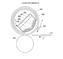
図2は、定着装置32の要部の横断面模式図である。401は被加熱体としての電磁誘導発熱性の定着ローラ、402は加圧ローラ、403は磁束発生手段としての励磁コイル−磁性体コアユニット、408は定着ローラ401に鎖交する磁束を遮断する磁束遮蔽板、409は温度センサである。410は被加熱材(用紙)であり、矢印c方向に搬送移動され、定着装置32により被加熱材上のトナーが被加熱材に定着される。
FIG. 2 is a schematic cross-sectional view of the main part of the fixing device 32. 401 is an electromagnetic induction heat generating fixing roller as a heated body, 402 is a pressure roller, 403 is an exciting coil-magnetic body core unit as magnetic flux generating means, and 408 is a magnetic flux that interrupts magnetic flux linked to the
定着ローラ401と加圧ローラ402は上下に並行に配列してそれぞれ両端側を不図示の軸受部材に回転自在に支持させてあり、加圧ローラ402をバネなどを用いた不図示の加圧機構によって定着ローラ401の回転軸方向に付勢して定着ローラ401の下面部に所定の加圧力で圧接させて圧接ニップ部(定着ニップ部)を形成させている。定着ローラ401は不図示の駆動機構により矢印bの時計方向に所定の周速度で回転駆動される。加圧ローラ402は圧接ニップ部での定着ローラ402との圧接摩擦力で定着ローラ401の回転に従動して回転する。
The
被加熱体としての電磁誘導発熱性の定着ローラ401は、本例では、外径32mm、厚さ0.5mmの鉄製の芯金シリンダを主体とするものである。電磁誘導発熱性の芯金シリンダはその他の材料として例えば磁性ステンレスのような磁性材料(磁性金属)といった、比較的透磁率μが高く、適当な抵抗率ρを持つ物を用いてもよい。
In this example, an electromagnetic induction heat-generating
芯金シリンダの外周面には定着ローラ表面の離型性を高めるために、例えばPTFEやPFA等のフッ素系樹脂の厚さ10〜50μmの離型層を設けてもよい。また芯金シリンダと離型層の間に所望の機能層、例えば、被加熱材と定着ローラ表面との密着性を高めるために耐熱性・弾性を有するゴム材や樹脂材の厚さ数100μmの弾性層などを設けてもよい。 In order to improve the releasability of the fixing roller surface on the outer peripheral surface of the mandrel cylinder, for example, a release layer having a thickness of 10 to 50 μm of a fluorine-based resin such as PTFE or PFA may be provided. In addition, a desired functional layer between the cored bar cylinder and the release layer, for example, a heat-resistant and elastic rubber material or resin material having a thickness of several hundreds of micrometers in order to improve the adhesion between the heated material and the surface of the fixing roller An elastic layer or the like may be provided.
加圧ローラ402は定着ローラ401に対して約30Kg重で加圧されており、その場合圧接ニップ部のニップ幅は約4mmになる。都合によっては荷重を変化させてニップ幅を変えてもよい。
The
磁束発生手段としての励磁コイル−磁性体コアユニット403は、励磁コイル404、磁性体コア405、アルミニウム製の保持ホルダー406、絶縁性の熱収縮性チューブ外被407等からなり、定着ローラ401内に挿入して配設してある。
An exciting coil-
励磁コイル404のコイル線材は、外径0.15〜0.50mmの絶縁被覆した導線を20〜150本リッツにしたものを用いている。より具体的に本例では、外径0.2mm、84本、総外径3mmのリッツ線をコイル線材として用いている。励磁コイル404が昇温した場合を考えて絶縁被覆には耐熱性の物を使用した。
As the coil wire of the
定着ローラ401の電磁誘導発熱を増加させるためには励磁コイル404に印加する交流電流の電流振幅を大きくすると良く、励磁コイル404のコイル線材の巻き数を減らしてやることが可能となるが、同時に励磁コイル404の電気抵抗による発熱も増加するので、本実施例では励磁コイル404のコイル線材の巻き数は8巻きとした。
In order to increase the electromagnetic induction heat generation of the fixing
磁性体コア405は、定着ローラ401の長手方向寸法に略対応した長さ寸法を有する横断面略半円状の横長部材で、半円弧面は定着ローラ内曲面に沿った形状に加工したものである。磁性体コア405は高透磁率かつ低損失のものを用いると良く、磁気回路の効率を上げるためと磁気遮蔽のために用いている。
The
アルミニウム製の保持ホルダー406は定着ローラ401の長手方向寸法よりも長い長さ寸法を有し、横断面略半円状の磁性体コア405の背面平面部の幅寸法に略対応した幅寸法を有し、比較的肉厚で剛性の有る横長板状部材である。
The holding
この励磁コイル404,磁性体コア405,保持ホルダー406の3者の外側に絶縁性の熱収縮性チューブ407を被せて該チューブを十分に熱収縮させる。絶縁性の熱収縮性チューブ407は例えばシリコン樹脂系あるいはフッ素樹脂系のものであり、本例では熱収縮前の外径40mm・厚さ0.3mmで、外径30mmに熱収縮させたとき肉厚が0.4mmとなる熱収縮性チューブを用いた。
An insulating heat-
熱収縮性チューブ407を十分に熱収縮させることで、平板状うず巻き型の励磁コイル404は磁性体コア405の半円弧面部に沿って成形される。すなわち定着ローラ内曲面に沿った形状に成形される。また励磁コイル404,磁性体コア405,保持ホルダー406の3者が一体に固定化されて励磁コイル−磁性体コアユニット403が構成される。
By sufficiently heat-shrinking the heat-
また、励磁コイル−磁性体コアユニット403の特に励磁コイル404の定着ローラ内曲面との対向面が絶縁性の熱収縮性チューブ407で覆われることで、該チューブ407が励磁コイル404と定着ローラ内曲面とを電気絶縁する役目も果たし、電気的安全性が向上する。
Further, the surface of the exciting coil-
前記励磁コイル−磁性体コアユニット403を定着ローラ401の中空内に挿入し、定着ローラ内曲面に沿った形状に成形されている励磁コイル404面部分を定着ローラ内曲面に近接させた所定の位置,角度姿勢にユニット403を調整して該ユニット403の保持ホルダー406の両端部を装置本体側の不図示の不動支持部にビス止めして固定支持させる。
The exciting coil-
本実施例では、定着ローラ401の横断面において、励磁コイル404の中央部が定着ローラ401と加圧ローラ402との圧接ニップ部よりも定着ローラ401の回転方向上流側にずれて位置するように励磁コイル−磁性体コアユニット401を図2のように傾かせた角度姿勢で配設している。これは励磁コイル404が対向している定着ローラ401の導電層が局部的に発熱するため、その発熱部が圧接ニップ部の直前になる様にすることで効率よく圧接ニップ部で被加熱材410を加熱するためである。
In the present exemplary embodiment, in the cross section of the fixing
磁束遮蔽板408は、それぞれ両端側を不図示の軸受部材に回転自在に支持させてあり、不図示のモータ(DCモータあるいはパルスモータでもよい)により矢印aの方向に回転移動でき、定着ローラ401と励磁コイル−磁性体コアユニット403との間に配置可能な構成となっている。
Both ends of the magnetic
次に磁束遮蔽板408の動作状態について説明する。図3は、図2の定着ローラ401とその内部を示す図および励磁コイル−磁性体コアユニット403により発生される磁束が定着ローラ401と鎖交する領域と磁束遮蔽板の位置関係を示す図であり、定着ローラ401の周方向に展開して示した図である。
Next, the operation state of the magnetic
図3(a)は定着ローラ軸方向に長い被加熱材を定着させる場合(例えばA4,A3等のサイズ)の位置関係を示す図である。この場合、励磁コイル−磁性体コアユニット403により発生される磁束が定着ローラ401と鎖交する領域が、磁束遮蔽板408によりさえぎられる部分はない状態である。
FIG. 3A is a diagram showing a positional relationship when a material to be heated that is long in the fixing roller axial direction is fixed (for example, A4, A3, etc.). In this case, the region where the magnetic flux generated by the exciting coil-
図3(b)は定着ローラ軸方向に短い被加熱材を定着させる場合(例えばA4R等のサイズ)の位置関係を示す図である。この場合、励磁コイル−磁性体コアユニット403により発生される磁束が定着ローラ401と鎖交する領域の両端が磁束遮蔽板408によりさえぎられている状態である。これにより定着ローラ軸方向に短い被加熱材を定着させる際に定着ローラ401の両端の温度上昇を防止することが可能である。
FIG. 3B is a diagram showing a positional relationship when a material to be heated that is short in the fixing roller axial direction is fixed (for example, a size such as A4R). In this case, both ends of the region where the magnetic flux generated by the exciting coil-
図4は、磁束遮蔽板の各種の構成を示す図である。磁束遮蔽板408は図4(a)に示す形状でもよい。図4(a)の磁束遮蔽板408は全ての被加熱材のサイズに対応できるような形状になっており、ステッピングモータなどのリニアに制御できる駆動源によって駆動される。また、磁束遮蔽板408は図4(b)に示す形状でもよい。図4(b)の磁束遮蔽板408は、片側基準で被加熱材を搬送する装置に搭載する磁束遮蔽板408であり、全てのサイズに対応できるような形状になっており、ステッピングモータなどのリニアに制御できる駆動源によって駆動される。また、磁束遮蔽板408は図4(c)に示す形状でもよい。図4(c)の磁束遮蔽板408は、全ての被加熱材のサイズに対応する必要がない装置において、DCモータなどの駆動源によって駆動される。
FIG. 4 is a diagram showing various configurations of the magnetic flux shielding plate. The magnetic
次に本実施例における処理ケースについて、図5〜図16を使って説明する。 Next, a processing case in the present embodiment will be described with reference to FIGS.
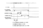
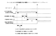
<ケース1>
被加熱材(例えば、シートやOHP用紙など)の搬送方向に交差(直交)する方向のサイズ(以下:単に「サイズ」という)における小サイズの被加熱材が定着装置に各種の搬送ローラによって搬送された後に大サイズの被加熱材が定着装置に各種の搬送ローラによって搬送された場合、例えば、A4Rサイズの被加熱材に対して画像形成(コピー)を行っている最中に、A4サイズの被加熱材に対して画像形成を行う要求(プリンタ要求)が来た場合の一連の処理について、図5のタイミングチャート、図6のフローチャートを用いて説明する。
<
A small-sized heated material in a size (hereinafter simply referred to as “size”) in a direction intersecting (orthogonal) the conveying direction of the heated material (for example, a sheet or OHP paper) is conveyed to the fixing device by various conveying rollers. In the case where a large-sized heated material is conveyed to the fixing device by various conveying rollers after the image is formed, for example, during image formation (copying) on an A4R-sized heated material, A series of processing when a request for image formation (printer request) for a material to be heated comes will be described with reference to a timing chart of FIG. 5 and a flowchart of FIG.
図5は、磁束調整手段の駆動タイミングを示すタイミングチャート(先行する被加熱材よりも後続の被加熱材のサイズが大きく、かつ非通材部の温度が所定の温度になる時間が所定時間より短い場合、ケース1とする)である。図6は、磁束調整手段の駆動制御による一連の処理を示すフローチャートである。図6のフローチャートに示す制御は、画像出力部10の本体制御部の指示および処理にもとづき、実行されている。
FIG. 5 is a timing chart showing the drive timing of the magnetic flux adjusting means (the time when the size of the subsequent heated material is larger than the preceding heated material and the temperature of the non-material passing portion is a predetermined temperature from a predetermined time. If it is short, it is referred to as
まず、コピージョブの被加熱材のサイズであるA4Rを検知して(S1)、それを図示しない画像形成装置内部のハードディスクに記憶しておく(S2)。 First, A4R, which is the size of the material to be heated in the copy job, is detected (S1) and stored in a hard disk inside the image forming apparatus (not shown) (S2).
コピージョブ中に被加熱材のサイズが変更しない場合(S3)は、磁束調整手段の駆動制御の処理を行わない。それに対して、コピージョブ中に、図5に示すタイミングでプリンタ要求が来た場合、プリンタ要求による被加熱材のサイズを検知して(S1)、その検知結果を図示しない画像形成装置内部のハードディスクに記憶する(S2)。 If the size of the material to be heated does not change during the copy job (S3), the drive control processing of the magnetic flux adjusting means is not performed. On the other hand, when a printer request is received at the timing shown in FIG. 5 during a copy job, the size of the material to be heated according to the printer request is detected (S1), and the detection result is not shown in the hard disk inside the image forming apparatus (not shown). (S2).
プリンタ要求によるジョブのサイズはA4なので、コピージョブのおける被加熱材のサイズから変更があることが検知できる(S3)。サイズの変更が検知できた場合、サイズが切り替わる直前の先行する被加熱材が定着装置を通材するまでの時間T1を算出する(S4)。なお、時間の算出方法は、実験データを基に作成されたテーブルから算出または予測するものでもよいし、また、被加熱材の搬送位置と被加熱材の搬送速度と被加熱材の搬送方向に平行する方向のサイズから算出または予測するものでもよい。 Since the job size according to the printer request is A4, it can be detected that there is a change from the size of the heated material in the copy job (S3). When the change in size is detected, a time T1 until the preceding heated material immediately before the size is changed passes through the fixing device is calculated (S4). The time calculation method may be calculated or predicted from a table created on the basis of experimental data, and may be determined in accordance with the transport position of the heated material, the transport speed of the heated material, and the transport direction of the heated material. It may be calculated or predicted from the size in the parallel direction.
次に、磁束調整手段である磁束遮蔽板を後続の被加熱材のサイズの応じた位置までに駆動するのにかかる時間T2を算出する(S5)。磁束調整手段は、定着ローラ内部にある励磁コイルが被加熱材の搬送方向に交差する方向に並列に複数配置されていて、複数の励磁コイルの駆動を組み合わせることで、作用磁束を調整するものでもよいし、励磁コイルの作用磁束が発生する方向とは逆の方向に同じく励磁コイルを配置し、反対方向の作用磁束を発生することで、全体の作用磁束を調整するものでもよい。算出方法としては、実験を基に得られたデータから算出または予測するものでもよいし、磁束遮蔽板の駆動速度などのパラメータから算出または予測するものでもよい。 Next, a time T2 required to drive the magnetic flux shielding plate as the magnetic flux adjusting means to a position corresponding to the size of the subsequent heated material is calculated (S5). The magnetic flux adjusting means includes a plurality of exciting coils inside the fixing roller arranged in parallel in a direction intersecting the conveying direction of the material to be heated, and adjusts the working magnetic flux by combining the driving of the plurality of exciting coils. Alternatively, the entire working magnetic flux may be adjusted by arranging the exciting coil in the opposite direction to the direction in which the working magnetic flux of the exciting coil is generated and generating the working magnetic flux in the opposite direction. As a calculation method, it may be calculated or predicted from data obtained based on experiments, or may be calculated or predicted from parameters such as the driving speed of the magnetic flux shielding plate.
次に定着装置の温度上昇が終了する時間T3を算出する(S6)。先行する被加熱材のサイズが後続の被加熱材のサイズより小さい場合、後続の被加熱材における定着装置の非通材部の温度が通材可能温度まで上昇する時間を算出する。なお、算出方法は、実験を基に得られたデータから算出または予測するものでもよいし、現状温度から目的温度までの加減速カーブによって目的温度までの時間を算出するものでもよい。 Next, a time T3 at which the temperature rise of the fixing device is completed is calculated (S6). When the size of the preceding material to be heated is smaller than the size of the subsequent material to be heated, the time required for the temperature of the non-material passing portion of the fixing device in the subsequent material to be heated to rise to the temperature at which the material can be passed is calculated. Note that the calculation method may be calculation or prediction from data obtained based on experiments, or calculation of time to the target temperature using an acceleration / deceleration curve from the current temperature to the target temperature.
次にS4,S5,S6で算出した、サイズが切り替わる直前の先行する被加熱材が定着装置を通材するまでの時間T1、磁束調整手段を駆動するのにかかる時間T2、定着装置の温度変化が終了する時間T3を基に磁束調整手段の駆動を開始する(F1)。 Next, the time T1 until the preceding material to be heated immediately before the size is switched, the time T2 required to drive the magnetic flux adjusting means, the time T2 required to drive the magnetic flux adjusting means, and the temperature change of the fixing device calculated in S4, S5, and S6. The driving of the magnetic flux adjusting means is started on the basis of the time T3 when the process ends (F1).
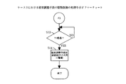
次にT1,T2,T3を基に磁束調整手段の駆動を開始する制御の詳細を図7をもって説明する。図7は、磁束調整手段の駆動制御の一例を示すフローチャートである。図7のフローチャートに示す制御は、画像出力部10の本体制御部の指示および処理にもとづき、実行されている。
Next, details of control for starting driving of the magnetic flux adjusting means based on T1, T2, and T3 will be described with reference to FIG. FIG. 7 is a flowchart showing an example of drive control of the magnetic flux adjusting means. The control shown in the flowchart of FIG. 7 is executed based on the instruction and processing of the main body control unit of the
まず、先行する被加熱材のサイズと後続の被加熱材のサイズを比較する(S7)。先行する被加熱材がA4Rで、後続の被加熱材はA4であるので、次にT1と(T2+T3)を比較する(S8)。ここまでが図5で示しているIで行う処理である。 First, the size of the preceding material to be heated is compared with the size of the subsequent material to be heated (S7). Since the preceding material to be heated is A4R and the subsequent material to be heated is A4, T1 and (T2 + T3) are then compared (S8). Up to this point, the processing performed by I shown in FIG.
次に、T1が大きい場合、Ta=T1−(T2+T3)時間分経過するまで磁束遮蔽板の駆動を待機する(S9)。Ta時間経過後、磁束調整手段である磁束遮蔽板を後続の被加熱材のサイズA4用に駆動する(S10)。このように制御を行うことで、図5に示すように、IIのタイミングで、サイズが切り替わる直前の先行する被加熱材が定着装置を通材するまでの時間T1経過と同時に、後続の被加熱材が通紙するのに然るべき温度に到達するので、定着の温度上昇を待ってから被加熱材を搬送するといったダウンタイムを削減でき、逆に後続の被加熱材が定着装置に到着するよりも早々に温度上昇が終了することによる、無駄な温度上昇を抑えることができ、定着装置とその近傍の劣化を解消し、耐久性に優れた装置を提供することができる。 Next, when T1 is large, the drive of the magnetic flux shielding plate is waited until Ta = T1- (T2 + T3) time elapses (S9). After the Ta time has elapsed, the magnetic flux shielding plate as the magnetic flux adjusting means is driven for the subsequent size A4 of the heated material (S10). By performing the control in this way, as shown in FIG. 5, at the timing of II, at the same time as the time T1 until the preceding heated material immediately before the size is switched passes through the fixing device, the subsequent heated material is heated. Since the temperature reaches an appropriate temperature for the material to pass through, it is possible to reduce downtime such as conveying the heated material after waiting for the fixing temperature to rise, and conversely, rather than the subsequent heated material arriving at the fixing device It is possible to suppress a useless temperature rise due to the end of the temperature rise quickly, eliminate the deterioration of the fixing device and its vicinity, and provide a device with excellent durability.
<ケース2>
次に、T1と(T2+T3)を比較するS8において、T1が小さい場合、つまり磁束調整手段である磁束遮蔽板408の駆動による定着装置の温度上昇が間に合わない場合の処理(F2)について、図8のタイミングチャートと図9のフローチャートで説明する。
<Case 2>
Next, in S8 for comparing T1 and (T2 + T3), the process (F2) in the case where T1 is small, that is, when the temperature rise of the fixing device due to driving of the magnetic
図8は、磁束調整手段の駆動タイミングを示すタイミングチャート(先行する被加熱材よりも後続の被加熱材のサイズが大きく、かつ非通材部の温度が所定の温度になる時間が所定時間より長い場合、ケース2とする)であり、図9は、磁束調整手段の駆動制御の一例を示すフローチャートである。 FIG. 8 is a timing chart showing the drive timing of the magnetic flux adjusting means (the time when the size of the subsequent material to be heated is larger than the preceding material to be heated and the temperature of the non-material passing portion is a predetermined temperature from a predetermined time. FIG. 9 is a flowchart showing an example of the drive control of the magnetic flux adjusting means.
I′のタイミングで前記で説明した通り、T1と(T2+T3)を比較した時にT1が小さい場合(S8)、即座に磁束調整手段である磁束遮蔽板408を後続の被加熱材のサイズに応じて駆動を開始する(S11)。ここまでが図8で示しているI′の制御である。そうすることで、後続の被加熱材の定着への到着を遅らせる必要があるが(S12)、サイズが切り替わる直前の先行する被加熱材が定着装置を通材してから、後続の被加熱材が定着装置に到着するまでの時間Ta′=(T2+T3)−T1を極力減少することができる。
As described above at the timing of I ′, when T1 is small when comparing T1 and (T2 + T3) (S8), the magnetic
<ケース3>
被加熱材(例えば、シートやOHP用紙など)の搬送方向に交差(直交)する方向のサイズにおける大サイズの被加熱材が定着装置に各種の搬送ローラによって搬送された後に小サイズの被加熱材が定着装置に各種の搬送ローラによって搬送された場合、例えば、A4サイズの被加熱材に対して画像形成(コピー)を行っている最中に、A4Rサイズの被加熱材に対して画像形成を行う要求(プリンタ要求)が来た場合(ケース3とする)の処理について、図10のタイミングチャート、図11のフローチャートを用いて説明する。
<
A small-sized material to be heated after a large-sized material to be heated in a direction intersecting (orthogonal) with a conveying direction of the material to be heated (for example, a sheet or OHP paper) is conveyed to the fixing device by various conveying rollers. Is conveyed to the fixing device by various conveying rollers, for example, during image formation (copying) on an A4 size heated material, image formation is performed on an A4R size heated material. Processing when a request (printer request) to be made (case 3) is received will be described with reference to the timing chart of FIG. 10 and the flowchart of FIG.
図10は、磁束調整手段の駆動タイミングを示すタイミングチャート(先行する被加熱材よりも後続の被加熱材のサイズが小さい場合)であり、図11は、磁束調整手段の駆動制御の一例を示すフローチャートである。図11のフローチャートに示す制御は、画像出力部10の本体制御部の指示および処理にもとづき、実行されている。
FIG. 10 is a timing chart showing the drive timing of the magnetic flux adjusting means (when the size of the subsequent heated material is smaller than the preceding heated material), and FIG. 11 shows an example of the drive control of the magnetic flux adjusting means. It is a flowchart. The control shown in the flowchart of FIG. 11 is executed based on the instruction and processing of the main body control unit of the
磁束調整手段の駆動制御による一連の処理(全体処理)は、すでにケース1において図6により説明した通りであり、ケース1とは異なる磁束調整手段の駆動制御についてのみ詳述する。
A series of processing (overall processing) by drive control of the magnetic flux adjusting means is as already described with reference to FIG. 6 in
図10に記述しているI″のタイミングでプリンタ要求が来た場合、コピージョブの被加熱材のサイズであるA4とプリント要求の後続の被加熱材のサイズであるA4Rとを比較して(図7のS7)、先行の被加熱材が大きい場合の制御として、磁束調整手段である磁束遮蔽板408を駆動制御する(F3)。F3の駆動制御としては、図11に示すとおり、サイズが切り替わる直前の先行する被加熱材が定着装置を通材するまでの時間T1経過するまで磁束遮蔽板408の駆動を待機する(S13)。
When a printer request comes at the timing of I ″ described in FIG. 10, A4 which is the size of the heated material of the copy job is compared with A4R which is the size of the heated material subsequent to the print request ( 7, as a control when the preceding material to be heated is large, the magnetic
図10に示すII′のタイミングであるT1時間経過した後で、後続の被加熱材のサイズに応じて磁束遮蔽板408の駆動を開始する(S14)。そうすることで、先行の被加熱材に対する定着不足,光沢ムラ,オフセット等の問題を削減することができる。また、後続の被加熱材が定着装置を通材すると、即座に磁束遮蔽板408の駆動を開始するので、後続の被加熱材としては、温度変化の影響を受けることなく、定着装置を通材することが可能で、しかも、定着装置の非通紙部において、無駄な温度上昇を抑えることができ、定着装置とその近傍の劣化を解消し、耐久性に優れた装置を提供することができる。
After the time T1 which is the timing of II ′ shown in FIG. 10 has elapsed, the driving of the magnetic
<ケース4>
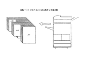
被加熱材(例えば、シートやOHP用紙など)の搬送方向に交差(直交)する方向のサイズにおける小サイズの被加熱材が定着装置に各種の搬送ローラによって搬送された後に大サイズの被加熱材が定着装置に各種の搬送ローラによって搬送される。さらに、大サイズの被加熱材が定着装置に各種の搬送ローラによって搬送された後に小サイズの被加熱材が定着装置に各種の搬送ローラによって搬送される。こうして出力することを回転ソートを呼ぶ。このように、交互に繰り返されるジョブ、例えば、図12に示すように画像形成された出力物に対してソートを行うために、A4RサイズとA4サイズの画像形成された出力物を交互に複数枚ずつ形成する場合について詳述する。図13のタイミングチャートとケース1で詳述した図6および図7のフローチャートを用いて説明する。
<Case 4>
A large-sized material to be heated after a small-sized material to be heated in a direction crossing (orthogonal to) a material to be heated (for example, a sheet or OHP paper) is conveyed to the fixing device by various conveying rollers. Is conveyed to the fixing device by various conveying rollers. Further, after the large-sized heated material is conveyed to the fixing device by various conveying rollers, the small-sized heated material is conveyed to the fixing device by various conveying rollers. This output is called rotational sorting. As described above, in order to sort the jobs that are alternately repeated, for example, the output products on which images are formed as shown in FIG. 12, a plurality of output products on which A4R size and A4 size images are formed alternately. The case where each is formed will be described in detail. This will be described with reference to the timing chart of FIG. 13 and the flowcharts of FIGS.
図13は、磁束調整手段の駆動タイミングを示すタイミングチャート(出力物を回転ソートする際に、先行する被加熱材よりも後続の被加熱材のサイズが大きく、かつ非通材部の温度が所定の温度になる時間が所定時間より短い場合、ケース4とする)である。 FIG. 13 is a timing chart showing the drive timing of the magnetic flux adjusting means (when the output is rotated and sorted, the size of the subsequent heated material is larger than the preceding heated material, and the temperature of the non-material passing portion is predetermined. If the time at which the temperature is reached is shorter than the predetermined time, it is referred to as Case 4).
まず、図13に示したIIIのタイミングでコピージョブスタート要求(プリンタ要求)を受けた段階で、被加熱材のサイズであるA4RとA4のサイズを検知して(S1)、それを図示しない画像形成装置内部のハードディスクに記憶しておく(S2)。 First, when a copy job start request (printer request) is received at the timing of III shown in FIG. 13, the sizes of A4R and A4, which are the sizes of the materials to be heated, are detected (S1), and an image (not shown) is displayed. It is stored in the hard disk inside the forming apparatus (S2).
プリンタ要求によるジョブの先行被加熱材のサイズはA4Rで、後続の被加熱材のサイズはA4なので、コピージョブのおける被加熱材のサイズから変更があることが検知できる(S3)。サイズの変更が検知できた場合、サイズが切り替わる直前の先行する被加熱材が定着装置を通材するまでの時間T1を算出する(S4)。なお、時間の算出方法は、実験データを基に作成されたテーブルから算出または予測するものでもよいし、被加熱材の搬送位置と被加熱材の搬送速度と被加熱材の搬送方向に平行する方向のサイズから算出または予測するものでもよい。 Since the size of the preceding heated material of the job according to the printer request is A4R and the size of the subsequent heated material is A4, it can be detected that there is a change from the size of the heated material in the copy job (S3). When the change in size is detected, a time T1 until the preceding heated material immediately before the size is changed passes through the fixing device is calculated (S4). The time calculation method may be calculated or predicted from a table created based on experimental data, and is parallel to the transport position of the heated material, the transport speed of the heated material, and the transport direction of the heated material. It may be calculated or predicted from the size of the direction.
次に、磁束調整手段である磁束遮蔽板を後続の被加熱材のサイズの応じた位置までに駆動するのにかかる時間T2を算出する(S5)。磁束調整手段は、定着ローラ内部にある励磁コイルが被加熱材の搬送方向に交差する方向に並列に複数配置されていて、複数の励磁コイルの駆動を組み合わせることで、作用磁束を調整するものでもよいし、励磁コイルの作用磁束が発生する方向とは逆の方向に同じく励磁コイルを配置し、反対方向の作用磁束を発生することで、全体の作用磁束を調整するものでもよい。算出方法としては、実験を基に得られたデータから算出または予測するものでもよいし、磁束遮蔽板の駆動速度などのパラメータから算出または予測するものでもよい。 Next, a time T2 required to drive the magnetic flux shielding plate as the magnetic flux adjusting means to a position corresponding to the size of the subsequent heated material is calculated (S5). The magnetic flux adjusting means includes a plurality of exciting coils inside the fixing roller arranged in parallel in a direction intersecting the conveying direction of the material to be heated, and adjusts the working magnetic flux by combining the driving of the plurality of exciting coils. Alternatively, the entire working magnetic flux may be adjusted by arranging the exciting coil in the opposite direction to the direction in which the working magnetic flux of the exciting coil is generated and generating the working magnetic flux in the opposite direction. As a calculation method, it may be calculated or predicted from data obtained based on experiments, or may be calculated or predicted from parameters such as the driving speed of the magnetic flux shielding plate.
次に定着装置の温度上昇が終了する時間T3を算出する(S6)。先行する被加熱材のサイズが後続の被加熱材のサイズより小さい場合、後続被の加熱材における定着装置の非通材部の温度が通材可能温度まで上昇する時間を算出する。なお、算出方法は、実験を基に得られたデータから算出または予測するものでもよいし、現状温度から目的温度までの加減速カーブによって目的温度までの時間を算出するものでもよい。 Next, a time T3 at which the temperature rise of the fixing device is completed is calculated (S6). When the size of the preceding material to be heated is smaller than the size of the subsequent material to be heated, the time during which the temperature of the non-material passing portion of the fixing device in the subsequent material to be heated rises to the temperature at which material can be passed is calculated. Note that the calculation method may be calculation or prediction from data obtained based on experiments, or calculation of time to the target temperature using an acceleration / deceleration curve from the current temperature to the target temperature.
次にS4、S5、S6で算出した、サイズが切り替わる直前の先行する被加熱材が定着装置を通材するまでの時間T1、磁束調整手段を駆動するのにかかる時間T2、定着装置の温度変化が終了する時間T3を基に磁束調整手段の駆動を開始する(F1)。 Next, the time T1 that is calculated in S4, S5, and S6 until the preceding material to be heated immediately before the size is switched passes through the fixing device, the time T2 that is required to drive the magnetic flux adjusting means, and the temperature change of the fixing device. The driving of the magnetic flux adjusting means is started on the basis of the time T3 when the process ends (F1).
次にT1,T2,T3を基に磁束調整手段の駆動を開始する制御の詳細を図7をよって説明する。図7は、磁束調整手段の駆動制御における一連の処理を示すフローチャートである。図7のフローチャートに示す制御は、画像出力部10の本体制御部の指示および処理にもとづき、実行されている。
Next, details of the control for starting the driving of the magnetic flux adjusting means based on T1, T2 and T3 will be described with reference to FIG. FIG. 7 is a flowchart showing a series of processes in the drive control of the magnetic flux adjusting means. The control shown in the flowchart of FIG. 7 is executed based on the instruction and processing of the main body control unit of the
まず、先行する被加熱材のサイズと後続の被加熱材のサイズを比較する(S7)。先行する被加熱材がA4Rで、後続被加熱材はA4であるので、次にT1と(T2+T3)を比較する(S8)。ここまでが図13で示しているIIIで行う処理である。 First, the size of the preceding material to be heated is compared with the size of the subsequent material to be heated (S7). Since the preceding material to be heated is A4R and the subsequent material to be heated is A4, T1 and (T2 + T3) are then compared (S8). The processing so far is the processing performed in III shown in FIG.
次に、T1が大きい場合、Ta=T1−(T2+T3)時間分経過するまで磁束遮蔽板の駆動を待機する(S9)。Ta時間経過後、磁束調整手段である磁束遮蔽板を後続の被加熱材のサイズA4用に駆動する(S10)。このように制御を行うことで、図13に示すように、IVのタイミングで、サイズが切り替わる直前の先行する被加熱材が定着装置を通材するまでの時間T1経過と同時に、後続の被加熱材が通紙するのに然るべき温度に到達するので、定着の温度上昇を待ってから被加熱材を搬送するといったダウンタイムを削減でき、逆に後続の被加熱材が定着装置に到着するよりも早々に温度上昇が終了することによる、無駄な温度上昇を抑えることができ、定着装置とその近傍の劣化を解消し、耐久性に優れた装置を提供することができる。 Next, when T1 is large, the drive of the magnetic flux shielding plate is waited until Ta = T1- (T2 + T3) time elapses (S9). After the Ta time has elapsed, the magnetic flux shielding plate as the magnetic flux adjusting means is driven for the subsequent size A4 of the heated material (S10). By performing the control in this way, as shown in FIG. 13, at the timing of IV, at the same time as the time T1 elapses until the preceding heated material immediately before the size is switched passes through the fixing device, the subsequent heated material is heated. Since the temperature reaches an appropriate temperature for the material to pass through, it is possible to reduce downtime such as conveying the heated material after waiting for the fixing temperature to rise, and conversely, rather than the subsequent heated material arriving at the fixing device It is possible to suppress a useless temperature rise due to the end of the temperature rise quickly, eliminate the deterioration of the fixing device and its vicinity, and provide a device with excellent durability.
<ケース5>
また、T1と(T2+T3)を比較した時に、T1が小さい場合、つまり磁束調整手段である磁束遮蔽板408の駆動による定着装置の温度上昇が間に合わない場合の処理(F2′)について、図14のタイミングチャートと図15のフローチャートを用いて説明する。
<Case 5>
FIG. 14 shows the processing (F2 ′) in the case where T1 is small when T1 is compared with (T2 + T3), that is, when the temperature rise of the fixing device due to driving of the magnetic
図14は、磁束調整手段の駆動タイミングを示すタイミングチャート(出力物を回転ソートする際に、先行する被加熱材よりも後続の被加熱材のサイズが大きく、かつ非通材部の温度が所定の温度になる時間が所定時間より長い場合、ケース5とする)である。図15は、磁束調整手段の駆動制御の一例を示すフローチャートである。 FIG. 14 is a timing chart showing the drive timing of the magnetic flux adjusting means (when the output is rotated and sorted, the size of the subsequent heated material is larger than that of the preceding heated material, and the temperature of the non-material passing portion is predetermined. If the time at which the temperature is reached is longer than the predetermined time, it is referred to as Case 5. FIG. 15 is a flowchart showing an example of drive control of the magnetic flux adjusting means.
図14に示すIII′のタイミングでコピー要求を受け付けた段階で、前記で説明した通り、T1と(T2+T3)を比較した時にT1が小さい場合、先行の被加熱材のサイズA4Rに応じて磁束調整手段である磁束遮断板408の駆動を行わない。しかし、後続の被加熱材のサイズA4に対しては定着装置の端部の昇温により、定着装置とその近傍の劣化を解消するために、コピージョブにおける被加熱材の最大サイズに応じて、磁束調整手段である磁束遮断板408の駆動を行う。つまり、後続の被加熱材のサイズA4に応じて磁束調整手段である磁束遮断板408の駆動を行う(S15)。そうすることで、先行の被加熱材に対しても、後続の被加熱材に対しても、定着不足,光沢ムラ,オフセット等の問題を削減することができる。
As described above, when T1 is small when T1 is compared with (T2 + T3) at the stage of accepting the copy request at the timing of III ′ shown in FIG. 14, the magnetic flux is adjusted according to the size A4R of the preceding material to be heated. The magnetic
また、後続の被加熱材としては、温度変化の影響を受けることなく、定着装置を通材することが可能で、しかも、被加熱材の最大サイズに応じて磁束遮蔽板408を駆動しているので、定着装置の非通紙部において、無駄な温度上昇を抑えることができ、定着装置とその近傍の劣化を解消し、耐久性に優れた装置を提供することができる。
Further, as a subsequent material to be heated, the fixing device can be passed without being affected by a temperature change, and the magnetic
<ケース6>
被加熱材(例えば、シートやOHP用紙など)の搬送方向に交差(直交)する方向のサイズにおける大サイズの被加熱材が定着装置に各種の搬送ローラによって搬送された後に小サイズの被加熱材が定着装置に各種の搬送ローラによって搬送される。さらに、大サイズの被加熱材が定着装置に各種の搬送ローラによって搬送された後に小サイズの被加熱材が定着装置に各種の搬送ローラによって搬送される。こうして出力することを回転ソートを呼ぶ。このように、交互に繰り返されるジョブ、例えば、図12に示すように画像形成された出力物に対してソートを行うために、A4RサイズとA4サイズの画像形成された出力物を交互に複数枚ずつ形成する場合について詳述する。
<
A small-sized material to be heated after a large-sized material to be heated in a direction crossing (orthogonal to) a material to be heated (for example, a sheet or OHP paper) is conveyed to the fixing device by various conveying rollers. Is conveyed to the fixing device by various conveying rollers. Further, after the large-sized heated material is conveyed to the fixing device by various conveying rollers, the small-sized heated material is conveyed to the fixing device by various conveying rollers. This output is called rotational sorting. As described above, in order to sort the jobs that are alternately repeated, for example, the output products on which images are formed as shown in FIG. 12, a plurality of output products on which A4R size and A4 size images are formed alternately. The case where each is formed will be described in detail.
図16のタイミングチャートとケース1で詳述した図6および図7のフローチャートとケース3で説明した図11のフローチャートを用いて説明する。
Description will be made with reference to the timing chart of FIG. 16, the flowcharts of FIGS. 6 and 7 described in detail in
図16は、磁束調整手段の駆動タイミングを示すタイミングチャート(出力物を回転ソートする際に、先行する被加熱材よりも後続の被加熱材のサイズが小さい場合、ケース6とする)である。
FIG. 16 is a timing chart showing the drive timing of the magnetic flux adjusting means (when the output product is rotationally sorted, it is referred to as
図16に記述しているIII″のタイミングでコピー要求が来た場合、コピージョブの先行の被加熱材のサイズであるA4と後続の被加熱材のサイズであるA4Rとを比較して(S7)、先行の被加熱材が大きい場合の制御として、磁束調整手段である磁束遮蔽板408を駆動制御する(F3)。
When a copy request is received at the timing of III ″ described in FIG. 16, A4 which is the size of the preceding heated material of the copy job is compared with A4R which is the size of the subsequent heated material (S7). ) As a control when the preceding material to be heated is large, the magnetic
F3の駆動制御としては、サイズが切り替わる直前の先行する被加熱材が定着装置を通材するまでの時間T1経過するまで磁束遮蔽板408の駆動を待機する(S13)。図16に示すIV′のタイミングであるT1時間経過した後で、後続の被加熱材のサイズに応じて磁束遮蔽板408の駆動を開始する(S14)。そうすることで、先行の被加熱材に対する定着不足,光沢ムラ,オフセット等の問題を削減することができる。
As drive control of F3, the drive of the magnetic
また、後続の被加熱材が定着装置を通材すると、即座に磁束遮蔽板408の駆動を開始するので、後続の被加熱材としては、温度変化の影響を受けることなく、定着装置を通材することが可能で、しかも、定着装置の非通紙部において、無駄な温度上昇を抑えることができ、定着装置とその近傍の劣化を解消し、耐久性に優れた装置を提供することができる。
Further, when the succeeding material to be heated passes through the fixing device, the driving of the magnetic
32 定着装置
401 定着ローラ
403 磁束発生手段
408 磁束遮蔽板
410 被加熱材
32
Claims (2)
先行する前記被加熱材の画像形成中に、後続の前記被加熱材のサイズを前記検知手段によって検知すると、前記先行する被加熱材のサイズに対し前記後続の被加熱材のサイズが変化するか否か判断し、サイズが変化すると判断した場合は、判断した時点から前記先行する被加熱材が前記定着手段を抜けるまでの第1の時間と、前記磁束調整手段の調整開始から前記定着手段が規定の温度に到達するまでにかかる第2の時間とを算出し、前記先行する被加熱材のサイズより前記後続の被加熱材のサイズが大きく、前記第1の時間が前記第2の時間より大きいときに、前記第1の時間から前記第2の時間を差し引いた時間だけ、前記判断した時点から前記磁束調整手段の調整開始タイミングを遅らせる制御手段を備えたことを特徴とする画像形成装置。 A conveying means for conveying the material to be heated; a detecting means for detecting the size of the material to be heated in a direction orthogonal to the conveying direction of the material to be heated; an induction heating element that generates electromagnetic induction heat by a magnetic flux generating means; In an image forming apparatus comprising: a fixing unit that includes a magnetic flux adjusting unit that adjusts a magnetic flux region applied to the induction heating element in a direction orthogonal to a conveyance direction.
Preceding said during image formation in the material to be heated, the subsequent the size of material to be heated is detected by the detecting means, whether the size of the subsequent material to be heated to the size of the material to be heated to the preceding changes If it is determined whether or not the size is changed, a first time from when the determination is made until the preceding material to be heated passes through the fixing unit and from the start of adjustment of the magnetic flux adjusting unit to the fixing unit Calculating the second time required until the temperature reaches a specified temperature, and the size of the subsequent heated material is larger than the size of the preceding heated material, and the first time is the second time. when larger, the first time period obtained by subtracting the second time from the time, the image forming, characterized in that from the point of the determination with a control means for delaying the adjustment start timing of said magnetic flux adjusting means Location.
前記磁束調整手段は、前記誘導発熱体に与える磁束領域を変化させる磁束遮蔽板を有し、この磁束遮蔽板を移動させることにより前記磁束調整手段の調整を行うことを特徴とする画像形成装置。 The image forming apparatus according to claim 1 .
The image forming apparatus, wherein the magnetic flux adjusting means includes a magnetic flux shielding plate that changes a magnetic flux region applied to the induction heating element, and the magnetic flux adjusting means is adjusted by moving the magnetic flux shielding plate.
Priority Applications (1)
| Application Number | Priority Date | Filing Date | Title |
|---|---|---|---|
| JP2003287707A JP4280580B2 (en) | 2003-08-06 | 2003-08-06 | Image forming apparatus |
Applications Claiming Priority (1)
| Application Number | Priority Date | Filing Date | Title |
|---|---|---|---|
| JP2003287707A JP4280580B2 (en) | 2003-08-06 | 2003-08-06 | Image forming apparatus |
Publications (3)
| Publication Number | Publication Date |
|---|---|
| JP2005055742A JP2005055742A (en) | 2005-03-03 |
| JP2005055742A5 JP2005055742A5 (en) | 2006-09-14 |
| JP4280580B2 true JP4280580B2 (en) | 2009-06-17 |
Family
ID=34366614
Family Applications (1)
| Application Number | Title | Priority Date | Filing Date |
|---|---|---|---|
| JP2003287707A Expired - Fee Related JP4280580B2 (en) | 2003-08-06 | 2003-08-06 | Image forming apparatus |
Country Status (1)
| Country | Link |
|---|---|
| JP (1) | JP4280580B2 (en) |
Families Citing this family (5)
| Publication number | Priority date | Publication date | Assignee | Title |
|---|---|---|---|---|
| JP2007226137A (en) * | 2006-02-27 | 2007-09-06 | Ricoh Co Ltd | Fixing device and image forming apparatus |
| JP4943810B2 (en) * | 2006-10-26 | 2012-05-30 | 株式会社リコー | Fixing apparatus and image forming apparatus |
| JP5157601B2 (en) * | 2008-04-03 | 2013-03-06 | 株式会社リコー | Image forming apparatus |
| JP5759173B2 (en) * | 2010-12-28 | 2015-08-05 | キヤノン株式会社 | Image forming apparatus |
| JP2014067009A (en) | 2012-09-06 | 2014-04-17 | Canon Inc | Image forming apparatus, and control method of image forming apparatus |
-
2003
- 2003-08-06 JP JP2003287707A patent/JP4280580B2/en not_active Expired - Fee Related
Also Published As
| Publication number | Publication date |
|---|---|
| JP2005055742A (en) | 2005-03-03 |
Similar Documents
| Publication | Publication Date | Title |
|---|---|---|
| JP4208815B2 (en) | Image heating device | |
| JP4314247B2 (en) | Image heating device | |
| US20110135358A1 (en) | Fixing device comprising auxiliary heat generating member and maintaining gap relative to separator | |
| JP2007226137A (en) | Fixing device and image forming apparatus | |
| JP2006120524A (en) | Heating device | |
| JP4208749B2 (en) | Image heating device | |
| JP4827478B2 (en) | Image heating device | |
| JP2006120533A (en) | Heating device | |
| JP2005196054A (en) | Image forming apparatus and fixing mechanism part controlling method | |
| JP4685235B2 (en) | Image forming apparatus | |
| JP4280580B2 (en) | Image forming apparatus | |
| JP2012230293A (en) | Fixing device and image forming apparatus having the same | |
| JP2001194940A (en) | Image heating device and image forming device | |
| JP2002258642A (en) | Image forming device | |
| JP2006106558A (en) | Image forming apparatus | |
| JP2004309651A (en) | Fixing device and image forming apparatus provided with fixing device | |
| JP5598167B2 (en) | FIXING DEVICE, ITS CONTROL METHOD, AND IMAGE FORMING DEVICE | |
| JP5137245B2 (en) | Fixing apparatus and image forming apparatus | |
| JP2005031550A (en) | Paper passing control method of fixing device | |
| JP2005173445A (en) | Fixing device and image forming apparatus | |
| JP2007310077A (en) | Image forming apparatus | |
| JP7134724B2 (en) | image heating device | |
| JP4570137B2 (en) | Fixing apparatus and image forming apparatus | |
| JP4340527B2 (en) | Fixing apparatus and image forming apparatus | |
| JP2005190729A (en) | Heating device and image forming device |
Legal Events
| Date | Code | Title | Description |
|---|---|---|---|
| A521 | Written amendment |
Free format text: JAPANESE INTERMEDIATE CODE: A523 Effective date: 20060728 |
|
| A621 | Written request for application examination |
Free format text: JAPANESE INTERMEDIATE CODE: A621 Effective date: 20060728 |
|
| A977 | Report on retrieval |
Free format text: JAPANESE INTERMEDIATE CODE: A971007 Effective date: 20081121 |
|
| A131 | Notification of reasons for refusal |
Free format text: JAPANESE INTERMEDIATE CODE: A131 Effective date: 20081209 |
|
| A521 | Written amendment |
Free format text: JAPANESE INTERMEDIATE CODE: A523 Effective date: 20090206 |
|
| TRDD | Decision of grant or rejection written | ||
| A01 | Written decision to grant a patent or to grant a registration (utility model) |
Free format text: JAPANESE INTERMEDIATE CODE: A01 Effective date: 20090310 |
|
| A01 | Written decision to grant a patent or to grant a registration (utility model) |
Free format text: JAPANESE INTERMEDIATE CODE: A01 |
|
| A61 | First payment of annual fees (during grant procedure) |
Free format text: JAPANESE INTERMEDIATE CODE: A61 Effective date: 20090316 |
|
| FPAY | Renewal fee payment (event date is renewal date of database) |
Free format text: PAYMENT UNTIL: 20120319 Year of fee payment: 3 |
|
| R150 | Certificate of patent or registration of utility model |
Free format text: JAPANESE INTERMEDIATE CODE: R150 |
|
| FPAY | Renewal fee payment (event date is renewal date of database) |
Free format text: PAYMENT UNTIL: 20130319 Year of fee payment: 4 |
|
| FPAY | Renewal fee payment (event date is renewal date of database) |
Free format text: PAYMENT UNTIL: 20140319 Year of fee payment: 5 |
|
| LAPS | Cancellation because of no payment of annual fees |