JP4280270B2 - Method for unindexing geometric primitives, rasterization device, and computer-readable medium - Google Patents
Method for unindexing geometric primitives, rasterization device, and computer-readable medium Download PDFInfo
- Publication number
- JP4280270B2 JP4280270B2 JP2006033226A JP2006033226A JP4280270B2 JP 4280270 B2 JP4280270 B2 JP 4280270B2 JP 2006033226 A JP2006033226 A JP 2006033226A JP 2006033226 A JP2006033226 A JP 2006033226A JP 4280270 B2 JP4280270 B2 JP 4280270B2
- Authority
- JP
- Japan
- Prior art keywords
- vertex
- data
- displayed
- rasterizer
- index
- Prior art date
- Legal status (The legal status is an assumption and is not a legal conclusion. Google has not performed a legal analysis and makes no representation as to the accuracy of the status listed.)
- Active
Links
- 238000000034 method Methods 0.000 title claims description 54
- 239000000872 buffer Substances 0.000 claims description 163
- 230000008569 process Effects 0.000 description 19
- 230000006870 function Effects 0.000 description 17
- 239000011159 matrix material Substances 0.000 description 10
- 238000009877 rendering Methods 0.000 description 5
- 238000007792 addition Methods 0.000 description 2
- 238000004590 computer program Methods 0.000 description 2
- 238000013500 data storage Methods 0.000 description 2
- 238000010586 diagram Methods 0.000 description 2
- 230000003287 optical effect Effects 0.000 description 2
- 238000006467 substitution reaction Methods 0.000 description 2
- 230000004075 alteration Effects 0.000 description 1
- 230000005540 biological transmission Effects 0.000 description 1
- 238000006243 chemical reaction Methods 0.000 description 1
- 230000001419 dependent effect Effects 0.000 description 1
- 239000012634 fragment Substances 0.000 description 1
- 230000007246 mechanism Effects 0.000 description 1
- 230000004048 modification Effects 0.000 description 1
- 238000012986 modification Methods 0.000 description 1
- 238000011112 process operation Methods 0.000 description 1
- 210000000352 storage cell Anatomy 0.000 description 1
- 230000009466 transformation Effects 0.000 description 1
- 230000000007 visual effect Effects 0.000 description 1
Images


Classifications
-
- G—PHYSICS
- G06—COMPUTING; CALCULATING OR COUNTING
- G06T—IMAGE DATA PROCESSING OR GENERATION, IN GENERAL
- G06T11/00—2D [Two Dimensional] image generation
- G06T11/40—Filling a planar surface by adding surface attributes, e.g. colour or texture
-
- G—PHYSICS
- G06—COMPUTING; CALCULATING OR COUNTING
- G06T—IMAGE DATA PROCESSING OR GENERATION, IN GENERAL
- G06T15/00—3D [Three Dimensional] image rendering
- G06T15/04—Texture mapping
Description
本発明は、一般にコンピュータグラフィックスのデータ処理に関する。 The present invention generally relates to computer graphics data processing.
今日のコンピュータグラフィックスは、シーンをキャプチャ/定義したり、電子表示装置上にシーンを描画したりするための様々な技術を利用している。そのような技術の一つは、多くの幾何プリミティブでシーンを規定することを伴う。幾何プリミティブは、特定の多角形形状を表す。例えば、幾何プリミティブは、三辺(三角形)、四辺(四角形)、五辺(五角形)、六辺(六角形)、その他であってよい。シーンの規定に使用される各幾何プリミティブは、その頂点によって特徴づけられる。シーンの個別の部分を表現するために、境界線が規定された領域内において特定の視覚効果を表示するように各幾何プリミティブを処理してもよい。 Today's computer graphics utilize various techniques for capturing / defining scenes and drawing scenes on electronic displays. One such technique involves defining a scene with a number of geometric primitives. A geometric primitive represents a specific polygonal shape. For example, geometric primitives may be three sides (triangles), four sides (quadrangles), five sides (pentagons), six sides (hexagons), and others. Each geometric primitive used to define the scene is characterized by its vertices. In order to represent individual parts of the scene, each geometric primitive may be processed to display a specific visual effect within the area where the boundary is defined.
シーンを規定する多数の幾何プリミティブは、それぞれ、対応するピクセルデータのセットに変換されて、電子表示装置上にシーン画像を描画する際に使用することができる。コンピュータグラフィックのシーンが多数の幾何プリミティブによって規定されることは、一般的である。したがって、あるシーンの幾何プリミティブを規定し描画することは、例えば頂点データ等の大量のデータを処理することを伴う。それゆえ、幾何プリミティブを使用するシーンの規定および描画にコンピュータグラフィックス技術を適用するとき、コンピュータグラフィックス技術の改善が引き続き必要とされている。 A number of geometric primitives that define the scene are each converted into a corresponding set of pixel data that can be used in rendering a scene image on an electronic display device. It is common for a computer graphic scene to be defined by a number of geometric primitives. Thus, defining and drawing geometric primitives for a scene involves processing a large amount of data, such as vertex data. Therefore, there is a continuing need for improvements in computer graphics techniques when applying computer graphics techniques to scene definition and rendering using geometric primitives.
一実施形態では、ピクセルシェーダを動作させて、表示される幾何プリミティブのインデックスを外す方法が開示される。この方法は、インデックスバッファ内で第1のテクスチャルックアップを実行して、表示される幾何プリミティブの頂点インデックス値を取得する操作を含む。この方法は、頂点バッファ内で第2のテクスチャルックアップを実行して、表示される幾何プリミティブについて既に取得された頂点インデックス値に対応する頂点データを取得する操作を含む。この方法は、表示される幾何プリミティブを規定するために必要な各頂点について、頂点データを取得する第1および第2のテクスチャルックアップを実行する操作を繰り返すことを含む。この方法はさらに、ピクセルシェーダ内から生成された既に取得した頂点データを使用して、表示される幾何プリミティブのラスタ化を実行する操作をさらに含む。 In one embodiment, a method for operating a pixel shader to unindex a displayed geometric primitive is disclosed. The method includes performing a first texture lookup in the index buffer to obtain a vertex index value for the displayed geometric primitive. The method includes performing a second texture lookup in the vertex buffer to obtain vertex data corresponding to the vertex index value already obtained for the displayed geometric primitive. The method includes repeating the operation of performing first and second texture lookups to obtain vertex data for each vertex required to define the displayed geometric primitive. The method further includes the operation of performing rasterization of the displayed geometric primitives using already acquired vertex data generated from within the pixel shader.
別の実施形態では、表示される幾何プリミティブのインデックスを外す方法が開示される。この方法は、ラスタライザを動作させて複数の頂点インデックス値をインデックスバッファから読み出す操作を含む。インデックスバッファから読み出される複数の頂点インデックス値は、表示される幾何プリミティブを規定するのに十分である。この方法は、ラスタライザを動作させて、頂点データを頂点バッファから読み出す操作を含む。頂点バッファから読み出される頂点データは、インデックスバッファから読み出された複数の頂点インデックス値のそれぞれに対応する。複数の頂点インデックス値はそれぞれ、頂点バッファ内の特定のエントリを参照する。この方法はさらに、ラスタライザを動作させて、表示される幾何プリミティブを頂点データにしたがってラスタ化する操作を含む。 In another embodiment, a method for unindexing displayed geometric primitives is disclosed. The method includes an operation of operating a rasterizer to read a plurality of vertex index values from an index buffer. The multiple vertex index values read from the index buffer are sufficient to define the geometric primitives to be displayed. The method includes an operation of operating a rasterizer to read vertex data from a vertex buffer. The vertex data read from the vertex buffer corresponds to each of a plurality of vertex index values read from the index buffer. Each of the plurality of vertex index values refers to a specific entry in the vertex buffer. The method further includes operating the rasterizer to rasterize the displayed geometric primitives according to the vertex data.
別の実施形態では、表示される幾何プリミティブをラスタ化する装置が開示される。この装置は、ラスタライザ内に定義され、表示される幾何プリミティブの頂点インデックス値を取得する第1テクスチャルックアップ回路を含む。頂点インデックス値は、インデックスバッファから取得されることになる。この装置は、ラスタライザ内に定義され、表示される幾何プリミティブについて既に取得された頂点インデックス値に対応する頂点データを第2テクスチャルックアップ回路を含む。頂点データは、頂点バッファから取得されることになる。第1および第2のテクスチャルックアップ回路は、表示される幾何プリミティブの頂点データの完全なセットを取得するよう動作するべく定義されている。この装置はさらに、ラスタライザ内に定義され、頂点データの完全なセットに基づいて、表示される幾何プリミティブのピクセルデータを生成するラスタ化回路を含む。 In another embodiment, an apparatus for rasterizing displayed geometric primitives is disclosed. The apparatus includes a first texture lookup circuit that is defined in the rasterizer and obtains the vertex index value of the displayed geometric primitive. The vertex index value is obtained from the index buffer. The apparatus includes a second texture lookup circuit for vertex data defined in the rasterizer and corresponding to the vertex index values already obtained for the displayed geometric primitive. Vertex data is obtained from the vertex buffer. The first and second texture lookup circuits are defined to operate to obtain a complete set of vertex data for the displayed geometric primitive. The apparatus further includes a rasterization circuit that is defined in the rasterizer and generates pixel data for the displayed geometric primitives based on the complete set of vertex data.
別の実施形態では、コンピュータ可読媒体が開示される。このコンピュータ可読媒体には、ピクセルシェーダを動作させて、表示される幾何プリミティブのインデックスを外すためのプログラム命令が格納されている。このコンピュータ可読媒体は、インデックスバッファ内で第1のテクスチャルックアップを実行して、表示される幾何プリミティブの頂点インデックス値を取得するプログラム命令を含む。このコンピュータ可読媒体は、頂点バッファ内で第2のテクスチャルックアップを実行して、表示される幾何プリミティブについて既に取得された頂点インデックス値に対応する頂点データを取得するプログラム命令を含む。このコンピュータ可読媒体は、表示される幾何プリミティブを規定するために必要な各頂点について、第1および第2のテクスチャルックアップを繰り返すプログラム命令を含む。このコンピュータ可読媒体はさらに、ピクセルシェーダ内から生成された既に取得した頂点データを使用して、表示される幾何プリミティブのラスタ化を実行するプログラム命令を含む。 In another embodiment, a computer readable medium is disclosed. This computer readable medium stores program instructions for operating a pixel shader to de-index the displayed geometric primitives. The computer-readable medium includes program instructions that perform a first texture lookup in an index buffer to obtain a vertex index value of a displayed geometric primitive. The computer-readable medium includes program instructions for performing a second texture lookup in the vertex buffer to obtain vertex data corresponding to the vertex index value already obtained for the displayed geometric primitive. The computer readable medium includes program instructions that repeat the first and second texture lookups for each vertex required to define the displayed geometric primitive. The computer-readable medium further includes program instructions for performing rasterization of the displayed geometric primitives using already acquired vertex data generated from within the pixel shader.
別の実施形態では、表示される幾何プリミティブをラスタ化する装置が開示される。この装置は、ラスタライザ内で第1のテクスチャルックアップを実行して、表示される幾何プリミティブの頂点インデックス値を取得する手段を含む。頂点インデックス値は、インデックスバッファから取得されることになる。この装置は、ラスタライザ内で第2のテクスチャルックアップを実行して、表示される幾何プリミティブについて既に取得された頂点インデックス値に対応する頂点データを取得する手段を含む。頂点データは、頂点バッファから取得されることになる。第1および第2のテクスチャルックアップを実行する手段は、表示される幾何プリミティブの頂点データの完全なセットを取得するように定義される。この装置はさらに、頂点データの完全なセットに基づいて、表示される幾何プリミティブのピクセルデータを生成する手段を含む。 In another embodiment, an apparatus for rasterizing displayed geometric primitives is disclosed. The apparatus includes means for performing a first texture lookup in the rasterizer to obtain vertex index values for displayed geometric primitives. The vertex index value is obtained from the index buffer. The apparatus includes means for performing a second texture lookup in the rasterizer to obtain vertex data corresponding to the vertex index values already obtained for the displayed geometric primitive. Vertex data is obtained from the vertex buffer. Means for performing the first and second texture lookups are defined to obtain a complete set of vertex data for the displayed geometric primitives. The apparatus further includes means for generating pixel data for the displayed geometric primitive based on the complete set of vertex data.
本発明の別の態様は、本発明の実施例として示される添付の図面と併せて、以下の詳細な説明からより明白になるであろう。 Other aspects of the invention will become more apparent from the following detailed description, taken in conjunction with the accompanying drawings, illustrated by way of example of the invention.
本発明および本発明のさらなる利点は、添付の図面と併せて以下の説明を参照することによって、最も良く理解することができる。 The invention and further advantages of the invention can be best understood by referring to the following description in conjunction with the accompanying drawings.
本発明がプロセス、装置、システム、デバイスまたは方法を含む多数の形式で実現されうることは認められよう。以下、添付の図面を参照して本発明の典型的な実施形態のいくつかについて詳細に説明する。 It will be appreciated that the present invention can be implemented in numerous forms, including a process, apparatus, system, device or method. Hereinafter, some exemplary embodiments of the present invention will be described in detail with reference to the accompanying drawings.
以下の説明では、本発明を完全に理解するために多数の具体的な詳細が記述される。しかしながら、本発明がこれらの具体的な詳細のいくつかまたは全てを用いずに実施されてもよいことは、当業者にとって明らかである。他の例において、周知のプロセス動作は、不必要に本発明を不明瞭にすることを避けるために詳述しなかった。 In the following description, numerous specific details are set forth in order to provide a thorough understanding of the present invention. However, it will be apparent to those skilled in the art that the present invention may be practiced without some or all of these specific details. In other instances, well known process operations have not been described in detail in order to avoid unnecessarily obscuring the present invention.
コンピュータグラフィックスにおける頂点インデックス付け(indexing:索引付けともいう)は、グラフィックスパイプラインを通して格納され送信される必要があるグラフィックスデータの量を減らすために実行される。一例として、頂点インデックス付けは即座に記述されてもよい。図1Aは、コンピュータディスプレイ上にグラフィックスイメージとして描画されるシーン内の二つの三角形(T0およびT1)を示す図である。三角形T0およびT1の各々は、三つの頂点によって規定される。三角形T0は、座標x=3、y=4の頂点A、座標x=4、y=1の頂点B、座標x=1、y=2の頂点Cによって規定される。三角形T1は、座標x=1、y=2の頂点C、座標x=4、y=1の頂点B、座標x=0、y=0の頂点Dによって規定される。三角形T0とT1が頂点C、Bを共有していることに注意されたい。 Vertex indexing (also called indexing) in computer graphics is performed to reduce the amount of graphics data that needs to be stored and transmitted through the graphics pipeline. As an example, vertex indexing may be described immediately. FIG. 1A is a diagram showing two triangles (T0 and T1) in a scene rendered as a graphics image on a computer display. Each of the triangles T0 and T1 is defined by three vertices. The triangle T0 is defined by a vertex A having coordinates x = 3 and y = 4, a vertex B having coordinates x = 4 and y = 1, and a vertex C having coordinates x = 1 and y = 2. The triangle T1 is defined by a vertex C with coordinates x = 1 and y = 2, a vertex B with coordinates x = 4 and y = 1, and a vertex D with coordinates x = 0 and y = 0. Note that triangles T0 and T1 share vertices C and B.
頂点インデックス付けを使用しない場合、各三角形T0、T1は、それぞれ三つの頂点によって規定される必要がある。図1Bは、各三角形T0、T1を記述するために必要な頂点データを含む、三角形についてインデックス付けされていないバッファを示す。図1Bに示すように、三角形T0は、頂点A、B、Cの座標によって規定される。また、三角形T1は、頂点C、B、Dの座標によって規定される。図1Bの最左列に示す数は、三角形についてのインデックス付けされていないバッファのインデックス値を表している。頂点インデックス付けを用いない場合、三角形T0とT1を規定するために六つの頂点座標エントリが必要であることが理解されよう。 If vertex indexing is not used, each triangle T0, T1 needs to be defined by three vertices, respectively. FIG. 1B shows an unindexed buffer for the triangles containing the vertex data needed to describe each triangle T0, T1. As shown in FIG. 1B, the triangle T0 is defined by the coordinates of the vertices A, B, and C. The triangle T1 is defined by the coordinates of the vertices C, B, and D. The numbers shown in the leftmost column of FIG. 1B represent the index value of the unindexed buffer for the triangle. It will be appreciated that if vertex indexing is not used, six vertex coordinate entries are required to define triangles T0 and T1.
図1Cは、頂点インデックス付けプロセスを実行するために使用される頂点バッファ(VB:Vertex Buffer)を示す。図1Cの頂点バッファ(VB)は、図1Aの三角形T0、T1を規定するために必要な頂点のデータを含む。座標によって規定される固有の頂点は、それぞれ頂点バッファ(VB)に一度格納される。したがって、三角形T0、T1を規定する必要に応じて、頂点バッファ(VB)は、頂点A、B、C、Dのそれぞれに対して一つのエントリを有する。図1Cの最左列に示す数は、頂点バッファ(VB)に格納された固有の頂点に対するインデックス値を表す。頂点バッファ(VB)を一次元の配列とみなすことができることが理解されよう。この一次元配列は、一次元、すなわち単一のインデックスによって検索され(navigate)、固有の頂点についての座標情報を格納したり座標情報にアクセスしたりすることができる。頂点バッファ(VB)は、図1Bのインデックス付けされていないバッファに含まれるような六つの頂点ではなく、四つの頂点についてそれぞれのデータを含んでいることが認められよう。このように、頂点バッファ(VB)を使用すると、頂点座標データを二重に記憶することが避けられる。さらに、頂点バッファ(VB)を使用すると、重複のない頂点データで操作(例えば変換、送信、その他)を実行することができる。 FIG. 1C shows a vertex buffer (VB) used to perform the vertex indexing process. The vertex buffer (VB) of FIG. 1C includes vertex data necessary to define the triangles T0 and T1 of FIG. 1A. Each unique vertex defined by coordinates is stored once in a vertex buffer (VB). Accordingly, the vertex buffer (VB) has one entry for each of the vertices A, B, C, and D as needed to define the triangles T0 and T1. The numbers shown in the leftmost column of FIG. 1C represent index values for unique vertices stored in the vertex buffer (VB). It will be appreciated that the vertex buffer (VB) can be viewed as a one-dimensional array. This one-dimensional array is navigated by one dimension, ie, a single index, and can store or access coordinate information about unique vertices. It will be appreciated that the vertex buffer (VB) contains data for each of four vertices, rather than six vertices as included in the unindexed buffer of FIG. 1B. Thus, using the vertex buffer (VB) avoids storing vertex coordinate data twice. Furthermore, using a vertex buffer (VB), operations (eg, conversion, transmission, etc.) can be performed on vertex data without duplication.
しかしながら、三角形T0とT1のそれぞれを完全に記述する頂点バッファ(VB)の使用を可能にするためには、各三角形に適切な頂点を関連付けるための仕組みを設ける必要がある。図1Dは、頂点バッファに含まれる適切な頂点と、三角形T0、T1のそれぞれとを関連付けるために定義されるインデックスバッファ(IB:Index Buffer)を示す。本実施例のインデックスバッファ(IB)は、二次元配列として定義される。第1の次元は、様々な三角形、例えばT0とT1を検索する(navigate)ために用いられ、第2の次元は、特定の三角形を規定するのに必要な三つの頂点を検索するために用いられる。第1の次元は、図1Dの最左列の数字によって表され、各三角形、例えばT0、T1、その他に対するインデックスとして表記される。第2の次元は、図1Dの最上行の数字によって表され、各三角形、すなわち0、1、2の各々の三つの頂点に対するインデックスとして表記される。第1次元および第2次元のインデックス値は、メモリ内のインデックスバッファ(IB)を定義するために用いられる検索可能なパラメータであることを認められよう。 However, in order to be able to use a vertex buffer (VB) that completely describes each of the triangles T0 and T1, it is necessary to provide a mechanism for associating an appropriate vertex with each triangle. FIG. 1D shows an index buffer (IB) defined for associating appropriate vertices included in the vertex buffer with each of the triangles T0 and T1. The index buffer (IB) of this embodiment is defined as a two-dimensional array. The first dimension is used to navigate various triangles, eg, T0 and T1, and the second dimension is used to retrieve the three vertices necessary to define a particular triangle. It is done. The first dimension is represented by the number in the leftmost column of FIG. 1D and is expressed as an index for each triangle, eg, T0, T1, etc. The second dimension is represented by the number in the top row of FIG. 1D and is expressed as an index for each triangle, ie, each of the three vertices of 0, 1, and 2. It will be appreciated that the first and second dimension index values are searchable parameters used to define an index buffer (IB) in memory.
インデックスバッファ(IB)には、頂点バッファ(VB)に格納された各三角形の頂点インデックス値に対応するデータが書き込まれる。インデックスバッファ(IB)内の特定のデータ項目を、IB[三角形番号、頂点番号]によって参照可能であることを考慮する。ここで、三角形番号はグラフィックスシーンにおける三角形の番号を参照し、頂点番号は、三角形番号に対応する三角形を規定するために必要な三つの頂点のそれぞれを参照する。したがって、IB[0,0..2]は、頂点インデックス値0、1、2を含む。ここで、頂点インデックス値0はVBにおける頂点Aを参照し、頂点インデックス値1はVBにおける頂点Bを参照し、頂点インデックス値2はVBにおける頂点Cを参照する。また、IB[1,0..2]は、頂点インデックス値2、1、3を含み、それぞれVBにおける頂点C、B、Dを参照する。
In the index buffer (IB), data corresponding to the vertex index value of each triangle stored in the vertex buffer (VB) is written. Consider that a particular data item in the index buffer (IB) can be referenced by IB [triangle number, vertex number]. Here, the triangle number refers to the triangle number in the graphics scene, and the vertex number refers to each of the three vertices necessary to define the triangle corresponding to the triangle number. Therefore, IB [0, 0. . 2] includes vertex index values 0, 1, and 2. Here, the
図1Bに関して述べた三角形表現に代わるものとして、三角形ストリップを使用してシーン内の三角形を表現することもできる。三角形ストリップでは、三角形は、一度に一つの頂点をステップする三つの頂点のグループからなる頂点の配列/バッファから暗黙的に定義される。図1Eは、図1Aの各三角形T0、T1を記述するために必要な頂点データを含む、インデックス付けされていない三角形ストリップバッファを示す。図1Eに示すように、三角形T0は頂点A、B、Cの座標によって規定される。また、三角形T1は頂点B、C、Dの座標によって規定される。 As an alternative to the triangle representation described with respect to FIG. 1B, triangle strips can also be used to represent the triangles in the scene. In a triangle strip, a triangle is implicitly defined from an array / buffer of vertices consisting of a group of three vertices that step one vertex at a time. FIG. 1E shows an unindexed triangle strip buffer that contains the vertex data needed to describe each triangle T0, T1 of FIG. 1A. As shown in FIG. 1E, the triangle T0 is defined by the coordinates of the vertices A, B, and C. The triangle T1 is defined by the coordinates of the vertices B, C, and D.
三角形ストリップについてもインデックス付けすることができる。例えば、図1Fは、図1Cの頂点バッファ(VB)に含まれる適切な頂点と、各三角形T0、T1とを関連付けるために定義された三角形ストリップインデックスバッファ(TSIB:Triangle Strip Index Buffer)を示す。本実施例の三角形ストリップインデックスバッファ(TSIB)は、三角形ストリップと同様の方法で定義される。しかしながら、三角形ストリップインデックスバッファ(TSIB)は、頂点バッファ(VB)に格納された各三角形の頂点インデックス値に対応するデータを含む。したがって、図1Fに関して、三角形T0は、頂点インデックス値0、1、2によって規定される。三角形T1は、頂点インデックス値1、2、3によって規定される。後述する本発明は、図1Aないし図1Dに関して上述したようなインデックス付けされた三角形と、図1A、図1C、図1E、図1Fに関して上述したようなインデックス付けされた三角形ストリップの両方のラスタ化(ラスタライズ)に等しく適用可能であることを認められよう。 Triangular strips can also be indexed. For example, FIG. 1F shows a triangle strip index buffer (TSIB) defined to associate the appropriate vertices contained in the vertex buffer (VB) of FIG. 1C with each of the triangles T0 and T1. The triangle strip index buffer (TSIB) of this embodiment is defined in the same way as the triangle strip. However, the triangle strip index buffer (TSIB) contains data corresponding to the vertex index value of each triangle stored in the vertex buffer (VB). Thus, with respect to FIG. 1F, the triangle T0 is defined by vertex index values 0, 1, and 2. The triangle T1 is defined by vertex index values 1, 2, and 3. The invention described below rasterizes both indexed triangles as described above with respect to FIGS. 1A-1D and indexed triangle strips as described above with respect to FIGS. 1A, 1C, 1E, and 1F. It will be appreciated that (rasterization) is equally applicable.
図1Aないし図1Fに示したように、多数の頂点が共有されている三角形で規定されたシーンにおいては特に、頂点インデックス付けは、格納および処理されるべき頂点データの量を削減するために有用であり得る。さらに、頂点インデックス付けは、頂点によって規定される本質的に任意の幾何なプリミティブについて実施可能であることを認められよう。例えば、上述した頂点インデックス付けは、三角形以外にも四辺、五辺、六辺その他の多角形の幾何プリミティブに対して適用可能である。議論を容易にするために、本発明の残りの部分では三角形を取り上げて説明する。しかしながら、本発明の原理は、頂点によって規定される任意の幾何プリミティブに対して等しく適用可能であることを理解されよう。 Vertex indexing is useful for reducing the amount of vertex data to be stored and processed, especially in scenes defined by triangles where many vertices are shared, as shown in FIGS. 1A-1F. It can be. Furthermore, it will be appreciated that vertex indexing can be performed on essentially any geometric primitive defined by vertices. For example, the above-described vertex indexing can be applied to geometric primitives of four sides, five sides, six sides and other polygons besides triangles. For ease of discussion, the remainder of the invention will be described by taking triangles. However, it will be appreciated that the principles of the present invention are equally applicable to any geometric primitive defined by vertices.
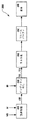
シーンの三角形を描画するピクセル処理を実行する前に、シーンの各三角形がその三つの頂点のそれぞれによって独立してかつ明示的に規定されるように、インデックスを外す(de-indexing)プロセスを実行する必要がある。図2は、シーンを表示するための頂点−ピクセルパイプライン200を示す。ここでは、シーンを規定する三角形に関連するデータを処理するために、頂点インデックス付けが使用される。頂点−ピクセルパイプライン200は、図1Aないし図1Fに関して上述したような頂点インデックス付けプロセスが、シーンを規定する各三角形について実行されたものと仮定する。したがって、適切な頂点バッファ(VB)と対応するインデックスバッファ(IB/TSIB)とが、表示されるべきシーンについて存在している。議論を容易にするために、本発明の残りの部分では、図1Aないし図1Dについて述べたような三角形のインデックス付けの文脈にしたがって説明をする。しかしながら、本発明の原理は、三角形ストリップのインデックス付けの文脈においても等しく適用可能であることを認められよう。
Perform a de-indexing process so that each triangle in the scene is independently and explicitly defined by each of its three vertices before performing pixel processing to draw the triangles in the scene There is a need to. FIG. 2 shows a vertex-
頂点−ピクセルパイプライン200は、頂点処理モジュール201を含む。頂点処理モジュールは、頂点バッファ(VB)と処理マトリックス(M)とを入力として受け取る。ここで、「入力として受け取る」という文言は、頂点処理モジュール201内のメモリへの入力ストリームとして関連するデータを実際に受け取ること、または、頂点処理モジュール201が頂点−ピクセルパイプライン200と通信してメモリからの関連データにアクセスして取り出せるようにすること、のいずれかとして実現可能であることを認められよう。頂点処理モジュール201は、頂点バッファ(VB)内の頂点データを変換して、スクリーン上、すなわちスクリーン空間に描画するのに適当な頂点データにするよう機能する。頂点処理モジュール201は、専用ハードウェア、ソフトウェアまたは専用のハードウェアとソフトウェアの組合せとして定義されてもよいことを認められよう。
The vertex-
処理マトリックス(M)は、頂点バッファ(VB)内の頂点データをスクリーン空間内に変換する手段を表す。様々な実施形態において、処理マトリックス(M)は、頂点データに対して多くの異なる変換操作を実行することができる。例えば、一実施例では、処理マトリックス(M)は、頂点バッファ(VB)内の各頂点を適切なピクセル位置に変換するように定義されることができる。別の実施例では、処理マトリックス(M)は、シーンを規定する三角形を適切に伸張したり(stretch)またはゆがめる(skew)ように、頂点バッファ(VB)内の各頂点を修正するように定義されることができる。当業者にとって周知のように、処理マトリックス(M)は、本質的に任意のグラフィックス処理技術によって頂点バッファ(VB)内の頂点を変換するように定義可能であることを認められよう。したがって、いくつかの実施形態では、処理マトリックス(M)は、頂点バッファ(VB)内の頂点に適用されるべき複雑な関数を表現することもできる。頂点バッファ(VB)内の頂点が処理マトリックス(M)によって変換されると、頂点バッファは(VB’)と表現される。頂点バッファ(VB’)は、(VB)に以前含まれたように、適切に変換されたものの、固有の頂点のそれぞれを含む。したがって、インデックスバッファ(IB)は、頂点バッファ(VB’)に対しても等しく適用することができる。 The processing matrix (M) represents a means for converting the vertex data in the vertex buffer (VB) into the screen space. In various embodiments, the processing matrix (M) can perform many different transformation operations on the vertex data. For example, in one embodiment, a processing matrix (M) can be defined to convert each vertex in the vertex buffer (VB) to an appropriate pixel location. In another embodiment, the processing matrix (M) is defined to modify each vertex in the vertex buffer (VB) so that the triangles defining the scene are properly stretched or skewed. Can be done. It will be appreciated that the processing matrix (M) can be defined to transform vertices in the vertex buffer (VB) by essentially any graphics processing technique, as is well known to those skilled in the art. Thus, in some embodiments, the processing matrix (M) can also represent a complex function to be applied to vertices in the vertex buffer (VB). When the vertices in the vertex buffer (VB) are transformed by the processing matrix (M), the vertex buffer is expressed as (VB '). The vertex buffer (VB ') contains each of the unique vertices, though properly transformed as previously included in (VB). Therefore, the index buffer (IB) can be equally applied to the vertex buffer (VB ′).
頂点−ピクセルパイプライン200は、インデックスを外すプロセスを実行して、シーン内に描画される各三角形の頂点データの完全なセットを生成する、インデックス外しモジュール203をさらに含む。インデックス外しモジュール203は、頂点バッファ(VB’)とインデックスバッファ(IB)とを入力として受け取る。ここで、「入力として受け取る」という文言は、インデックス外しモジュール203内のメモリへの入力ストリームとして関連するデータを実際に受け取ること、または、インデックス外しモジュール203が頂点−ピクセルパイプライン200と通信してメモリからの関連データにアクセスして取り出せるようにすること、のいずれかとして実現可能であることを認められよう。本実施形態では、インデックス外しモジュール203は、頂点−ピクセルパイプライン200内の専用のハードウェア要素として定義される。
The vertex-
インデックス外しモジュール203は、インデックスバッファ(IB)内に表現される各三角形の各頂点を明示的に規定するように機能する。したがって、インデックス外しモジュール203は、インデックスバッファ(IB)内の各三角形の各頂点について格納された頂点インデックス値を使用して、頂点バッファ(VB’)から対応する頂点データを取り出す。各三角形の各頂点について引き出された頂点データは、頂点−ピクセルパイプライン200内でインデックス外しモジュール203からラスタ化モジュール205に送信される。したがって、シーン内の各三角形(すなわち、T0からTN−1、但しNはシーン内の三角形の総数を表す)について、インデックス外しモジュール203は、インデックスバッファ(IB)に格納された頂点インデックス値にしたがって、対応する頂点データを頂点バッファ(VB’)からラスタ化モジュール205に送信するように機能する。
The
ラスタ化モジュール205は、インデックス外しモジュール203から受け取った頂点データにより規定される各三角形を描画するためのピクセル値を規定するように機能する。各三角形の描画には、頂点のピクセルを描画するだけでなく、三角形の境界内部のピクセルも描画することも含まれることは認められよう。したがって、ラスタ化モジュール205により規定される各三角形のピクセル値は、三角形の頂点ピクセル値と、三角形の境界内部のピクセル値の両方を含む。
The
表示のためにラスタ化モジュール205によって規定されるピクセル値は、フレームバッファ207に格納される。フレームバッファ207は、ディスプレイ、例えばスクリーンの各ピクセルについての適当な数の記憶セルを含む。フレームバッファ207に格納されるピクセルデータは、表示モジュール209に送信され、そこで適切に処理されて表示される。当業者は、フレームバッファ207および表示モジュール209の詳細な機能を理解するだろう。
Pixel values defined by the
一実施形態では、フレームバッファ207は、ラスタ化モジュール205と関連付けられた大規模メモリの一部として定義される。大規模メモリは、一つ以上の表示用のフレームバッファ、頂点データ(例えば、VB、VB’)、インデックスデータ(例えば、IB)、テクスチャ、および他のデータを折々保持するために使用することができる。大規模メモリの割り当ては柔軟である。例えば、特定アドレスのメモリは、あるときはフレームバッファの一部であり、別のときはテクスチャの一部であり、さらに別のときは頂点アレイの一部であってもよい。
In one embodiment, the
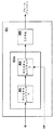
図3は、本発明の一実施形態にしたがった、強化された頂点−ピクセルパイプライン300を示す。図2に関して上述したように、強化された頂点−ピクセルパイプライン300は、頂点処理モジュール201、フレームバッファ207、および表示モジュール209を含む。しかしながら、強化された頂点−ピクセルパイプライン300は、インデックス外しモジュール203を含まない。また、強化された頂点−ピクセルパイプライン300は、インデックス外しラスタ化モジュール301を含む。
FIG. 3 illustrates an enhanced vertex-
上述したように、頂点処理モジュール201は、頂点バッファ(VB)と処理マトリックス(M)とを入力として受け取る。処理マトリックス(M)にしたがって、頂点処理モジュール201は、頂点バッファ(VB)内の頂点データをスクリーン上の描画に適した頂点データに変換するように機能する。変換された頂点データは、頂点バッファ(VB’)に格納されるものとして表現される。頂点バッファ(VB’)は、インデックス外しラスタ化モジュール301が利用できるようにされる。
As described above, the
インデックス外しラスタ化モジュール301は、頂点バッファ(VB’)とインデックスバッファ(IB)とを入力として受け取る。ここで、「入力として受け取る」という文言は、インデックス外しラスタ化モジュール301内のメモリへの入力ストリームとして関連するデータを実際に受け取ること、または、インデックス外しラスタ化モジュール301が強化された頂点−ピクセルパイプライン300と通信してメモリからの関連データにアクセスして取り出せるようにすること、のいずれかとして実現可能であることを認められよう。インデックス外しラスタ化モジュール301は、インデックス外し機能301aを含む。インデックス外し機能301aは、インデックスバッファ(IB)内の各三角形の各頂点について格納された頂点インデックス値を使用して、頂点バッファ(VB’)から対応する頂点データを取得するように定義される。各三角形の各頂点について頂点バッファ(VB’)から取得された頂点データは、続いて、インデックス外しラスタ化モジュール301により処理されて、各三角形を描画するためのピクセルデータを規定する。インデックス外しラスタ化モジュール301によって規定されたピクセルデータは、フレームバッファ207に格納される。それから、フレームバッファ207に格納されたピクセルデータは、表示モジュール209に送信され、そこで適切に処理されて表示される。
The
一実施形態では、強化された頂点−ピクセルパイプライン300のインデックス外しラスタ化モジュール301は、頂点−ピクセルパイプライン200のラスタ化モジュール205と同等のハードウェアであるように定義される。しかしながら、本実施形態では、インデックス外しラスタ化モジュール301はインデックス外し機能301aを提供するようにプログラムされる一方で、ラスタ化モジュール205はそうでない。したがって、強化された頂点−ピクセルパイプライン300のインデックス外しラスタ化モジュール301を使用すれば、インデックス外しモジュール203の専用ハードウェアは必要でない。
In one embodiment, the enhanced vertex-
図4は、本発明の一実施形態によるインデックス外しラスタ化モジュール301を示す。上述のように、インデックス外しラスタ化モジュール301はインデックス外し機能301aを含む。図4において、インデックス外し機能301aは、第1のテクスチャルックアッププロセス401を実行する手段と、第2のテクスチャルックアッププロセス403を実行する手段とを含むものとして表されている。当業者は、ラスタ化モジュールの文脈において、テクスチャルックアップ(検索)とは、ラスタ化モジュールがメモリ位置(例えばキャッシュ、RAM等)における幾何プリミティブデータにアクセスして読み幾何プリミティブデータを読み出すプロセスのことを指すことを認められよう。第1および第2のテクスチャルックアッププロセス(401、403)を実行するための手段が、インデックス外しラスタ化モジュール301の範囲内で規定される回路を含んでもよいことを認められよう。回路、または回路の一部は、機能専用として設計されてもよいし、必要な機能を実行するようプログラムされたものとして設計されてもよい。
FIG. 4 illustrates a
第1のテクスチャルックアッププロセス401において、インデックス外しラスタ化モジュール301は、インデックスバッファ(IB)内でのテクスチャルックアップを実行して、三角形の頂点インデックス値を取得するようにプログラムされる。第2のテクスチャルックアッププロセス403において、インデックス外しラスタ化モジュール301は、第1のテクスチャルックアッププロセス401で取得された頂点インデックス値を使用して、頂点バッファ(VB)から対応する頂点データを取得するようにさらにプログラムされる。第2のテクスチャルックアッププロセス403において頂点バッファVB’から取得されたデータは、三角形の各頂点を明示的に規定する。第2のテクスチャルックアッププロセス403において頂点バッファVB’から取得されるデータは、三角形を描画するためのピクセルデータを規定するためにラスタ化モジュール405により使用される。上述したように、三角形の描画には、頂点ピクセルを描画するだけでなく、三角形の境界内部のピクセルを描画することも含まれる。したがって、ラスタ化モジュール405は、三角形の各頂点と三角形の境界内部の領域のピクセルデータを規定する。それから、上述したように、ラスタ化モジュール405により規定されたピクセルデータは、インデックス外しラスタ化モジュール301からフレームバッファ207に送信される。
In the first
ラスタ化モジュール405は、幾何プリミティブのピクセルデータを生成する手段を表していることを認められよう。幾何プリミティブは、対応する頂点データの完全セットに基づいて表示される。ラスタ化モジュール405は、インデックス外しラスタ化モジュール301内の回路として定義されてもよい。回路、または回路の一部は、機能専用として設計されてもよいし、必要な機能を実行するようプログラムされたものとして設計されてもよい。
It will be appreciated that the
上述したように、インデックス外しラスタ化モジュール301を含む強化された頂点−ピクセルパイプライン300は、本明細書で言及した例示の三角形以外にも、任意の幾何プリミティブに関して使用することができる。さらに、各幾何プリミティブの各頂点を規定するデータは、最小限必要な二次元の空間座標x、y以外にも、任意の数の座標および属性にまで拡張することができる。各頂点を規定するデータは座標に限定されないことを認められよう。例えば、各頂点に割り当てられる色データがあってもよい。各頂点を規定するためにより多数の座標および/または属性が使用される実施形態では、頂点バッファ(VBおよびVB’)は、各固有の頂点についての追加的なデータに対応するように適切に拡張される。また、インデックス外しラスタ化モジュール301は、第2のテクスチャルックアッププロセス403において、頂点バッファVB’から適切に拡張された座標情報を取得するようにプログラムされる。単一のパスでテクスチャとしてアクセス可能な各頂点におけるデータのタイプまたは数、もしくは、単一のパスで書き込み可能なデータのタイプまたは数のいずれかを、インデックス外しラスタ化モジュール301が制限する場合、全ての頂点データのインデックスを外すために複数のパスを使用してもよいことを認められよう。また、インデックス外しラスタ化モジュール301は、インデックス外し(de-indexing:デインデクシング)ピクセルシェーダ、インデックス外しグラフィックスシンセサイザ、ラスタライザ、ピクセルシェーダ、グラフィックスシンセサイザ、またはフラグメントシェーダと呼ばれてもよいことも認められよう。
As described above, the enhanced vertex-
上述にしたがって、本発明のインデックス外しラスタ化モジュール301は、ラスタ化モジュール205でなされたように明示的な三角形頂点データを入力として受け取るのではなく、インデックスバッファ(IB)と頂点バッファ(VB’)の両方を入力として受け取るようにプログラムされる。また、本発明のインデックス外しラスタ化モジュール301は、二回のテクスチャルックアップを実行して明示的な三角形頂点データを取得するようにプログラムされており、その結果、インデックス外しプロセスが効率的に実行される。さらに、本発明のインデックス外しラスタ化モジュール301は、二回のテクスチャルックアップを実行することによって取得された明示的な三角形頂点データを使用して、対応する三角形を描画するためのピクセルデータを規定するようにプログラムされている。本発明のインデックス外しラスタ化モジュール301を使用すれば、頂点−ピクセルパイプラインからインデックス外しモジュール203の専用ハードウェアを取り除いてもよいことを認められよう。
In accordance with the above, the
一実施形態では、インデックス外しラスタ化モジュール301は、インデックス外しラスタ化モジュール301と関連するメモリ内に一時バッファを作成する。一時「フレーム」バッファに書き込まれたデータが表示されることになっていない場合でも、一時バッファを一時「フレーム」バッファとみなすことができる。議論を容易にするために、一時バッファという用語を使用する。一時バッファは、第1のテクスチャルックアップにおいてインデックス外しされた頂点データをインデックス外しラスタ化モジュール301が書き込むことができるメモリ空間を表す。インデックス外しラスタ化モジュール301がピクセル単位で一時バッファを観察し、各ピクセルが一時バッファの特定の位置に割り当てられていることを認められよう。したがって、一時バッファの各「ピクセル」を活動化させるために、インデックス外しラスタ化モジュール301を動作させて、一時バッファを範囲に含むダミー図形(dummy geometry)を描画させる。一実施形態では、ダミー図形は一つまたは二つの大きな三角形として描画される。
In one embodiment, the
インデックス外しされた頂点データを格納するために一時バッファが使用されるので、一時バッファにおける各ピクセル位置を、インデックス外しされた頂点データを格納するためのメモリのユニットとみなすことができる。使用される頂点データを入力として書き込むための、インデックス外しラスタ化モジュール301用の出力バッファとして一時バッファを使用するので、インデックス外しラスタ化モジュール301は頂点データ型の出力をサポートする必要がある。場合によっては、複数の出力要素を使用して所与の頂点のデータ要素を形成してもよいし、および/または複数のピクセルを使用して所与の頂点を形成してもよい。例えば、ハードウェアがピクセル毎に最大32ビットを書き込み可能であり、頂点毎に四つの32ビット浮動値が存在する場合、四つのピクセルを使用して単一の頂点を記述してもよい。また、一時バッファ内に表現された各ピクセルを、自身のプログラムを実行して一時バッファ内の自身のメモリ位置に書き込まれるべきデータの内容を決定するものと見ることもできる。各ピクセルのプログラム動作は同一である。しかしながら、各ピクセルに関連付けられるデータはそれぞれ異なる。
Since a temporary buffer is used to store the unindexed vertex data, each pixel location in the temporary buffer can be regarded as a unit of memory for storing the unindexed vertex data. Since the temporary buffer is used as the output buffer for the
一時バッファ内で表現された各ピクセルは、一時バッファ内の自身の位置に書き込まれるべき頂点データを知っている必要がある。一時バッファ内の特定のピクセル位置に書き込まれるべき頂点データは、一時バッファ内の特定のピクセル位置のメモリアドレスに依存する。一時バッファ内の特定のピクセル位置のメモリアドレスは、一時バッファの始めからのオフセットに関して考慮されてもよい。一実施形態では、ピクセルは自身のメモリ位置を照会してもよい。別の実施形態では、ピクセルは、自身の一時バッファの位置に基づく数式を計算して、自身のメモリ位置を発見してもよい。 Each pixel represented in the temporary buffer needs to know the vertex data to be written to its location in the temporary buffer. The vertex data to be written to a specific pixel location in the temporary buffer depends on the memory address of the specific pixel location in the temporary buffer. The memory address of a particular pixel location in the temporary buffer may be considered with respect to the offset from the beginning of the temporary buffer. In one embodiment, a pixel may query its memory location. In another embodiment, a pixel may calculate a formula based on the location of its temporary buffer to find its memory location.
各ピクセルが、一時バッファ内の自身のメモリ位置に書き込む必要のある頂点インデックスを知ると、ピクセルは、テクスチャとして構成されたインデックスバッファ(IB)内の第1のテクスチャルックアップにおけるテクスチャ座標として頂点インデックスを使用する。それから、ピクセルは一時バッファ内の自身の位置に、戻された頂点データを書き込む。一時バッファが書き込まれた後、インデックス外しラスタ化モジュール301は、第2のテクスチャルックアップで読み出される頂点データ入力として一時バッファを使用して、ディスプレイフレームバッファ207への出力として構成される。元の頂点データ(VB/VB’)およびインデックスデータ(IB)は、廃棄されてもよいし、または次のフレームのために保存されてもよい。
When each pixel knows the vertex index that needs to be written to its memory location in the temporary buffer, the pixel is the vertex index as the texture coordinate in the first texture lookup in the index buffer (IB) configured as a texture. Is used. The pixel then writes the returned vertex data to its location in the temporary buffer. After the temporary buffer is written, the
本発明は、テクスチャとしてインデックスデータと頂点データとを使用するので、インデックス外しラスタ化モジュール301が、インデックスデータフォーマット(例えば、8ビット、16ビット、または32ビット整数)と頂点データフォーマット(例えば、固定または浮動)の両方でテクスチャをサポートする必要がある。また、インデックス外しラスタ化モジュール301は、一次元のテクスチャ、またはN×1である二次元のテクスチャとして、インデックスデータと頂点データとにアクセスするのをサポートするように定義されてもよい。インデックス外しラスタ化モジュール301はまた、数式、例えばハードウェア依存の数式にテクスチャ座標を通すことによって、一般の二次元テクスチャとしてインデックスデータと頂点データとにアクセスするように定義されてもよい。
Since the present invention uses index data and vertex data as textures, the
図5は、本発明の一実施形態にしたがって、ピクセルシェーダを動作させ、表示される幾何プリミティブのインデックス外しを実行する方法のフローチャートを示す。この方法は、インデックスバッファで第1のテクスチャルックアップを実行して、表示される幾何プリミティブについての頂点インデックス値を取得する操作501を含む。この方法は、頂点バッファで第2のテクスチャルックアップを実行して、操作501で既に取得された頂点インデックス値に対応する頂点データを取得する操作503も含む。一実施形態では、頂点バッファ内に含まれる頂点データは、第2のテクスチャルックアップを実行する前にスクリーン空間内で処理される。また、一実施形態では、操作501と操作503とを実行する前に、インデックスバッファと頂点バッファがピクセルシェーダ内のメモリにそれぞれ送信される。さらに、一実施形態では、操作503で取得された頂点データは、フレームバッファのスクラッチ(作業用)部分に格納される。フレームバッファのスクラッチ部分に格納されたデータは、明示的に表示されることはない。
FIG. 5 shows a flowchart of a method for operating a pixel shader and performing de-indexing of displayed geometric primitives, in accordance with one embodiment of the present invention. The method includes an
この方法は、表示される幾何プリミティブを規定するために必要な各頂点について、操作501と操作503とを連続的に繰り返す操作505をさらに含む。一実施形態では、表示される幾何プリミティブは三角形である。したがって、この実施形態では、操作501と操作503は、各三角形について合計で三回、すなわち、各三角形の三つの頂点のそれぞれについて一回ずつ実行される。操作507において、表示される幾何プリミティブがラスタライズされる。操作507のラスタライズは、操作501と操作503の連続的実行によって既に取得された頂点データを使用して、実行される。操作501ないし507は、シーン内で表示される幾何プリミティブのそれぞれについて繰り返される。
The method further includes an
図6は、本発明の一実施形態にしたがって、表示される幾何プリミティブをインデックスを外す方法のフローチャートを示す。この方法は、ラスタライザを動作させて、表示される幾何プリミティブを規定するのに十分な複数の頂点インデックス値をインデックスバッファから読み出す操作601を含む。一実施形態では、表示される幾何プリミティブは、三つの頂点を有する三角形として表現される。この方法は、ラスタライザを動作させて、頂点バッファから頂点データを読み出す操作603も含む。これらの頂点データは、操作601でインデックスバッファから読み出された複数の頂点インデックス値のそれぞれと対応する。複数の頂点インデックス値のそれぞれは、頂点バッファ内の特定のエントリを参照する。
FIG. 6 shows a flowchart of a method for unindexing displayed geometric primitives in accordance with one embodiment of the present invention. The method includes an operation 601 that operates a rasterizer to read a plurality of vertex index values from an index buffer sufficient to define a displayed geometric primitive. In one embodiment, the displayed geometric primitive is represented as a triangle having three vertices. The method also includes an
一実施形態では、頂点バッファ内に含まれる頂点データは、操作603を実行する前にスクリーン空間内で処理される。また、一実施形態では、操作601と操作603を実行してインデックスバッファと頂点バッファから読み出しをする前に、インデックスバッファと頂点バッファとがラスタライザ内のメモリに送信される。別の実施形態では、操作603で取得された頂点データは、フレームバッファのスクラッチ部分に格納される。フレームバッファのスクラッチ部分に格納されたデータは、表示されることはない。この方法は、ラスタライザを動作させ、操作603で読み出された頂点データにしたがって、表示される幾何プリミティブをラスタ化する操作605をさらに含む。
In one embodiment, vertex data contained in the vertex buffer is processed in screen space before performing
本明細書で述べた本発明の実施形態は、コンピュータ機器に組み込まれてもよい。コンピュータ機器はテレビゲーム機として表現されてもよい。本明細書で述べた実施形態は、ハードウェア、ソフトウェアまたはそれらの組合せとして実現可能であることを認められよう。 The embodiments of the invention described herein may be incorporated into computer equipment. The computer device may be expressed as a video game machine. It will be appreciated that the embodiments described herein can be implemented as hardware, software, or a combination thereof.
上述の実施形態を念頭において、本発明は、コンピュータシステムに格納されたデータに関わる様々なコンピュータ実装の操作を採用可能であることを理解されたい。これらの操作は、物理量の物理的な操作を必要とするものである。通常は、しかし必須ではなく、これらの量は、格納され、転送され、組み合わされ、比較されまたは他の操作を受けることができる電気信号または磁気信号の形態をとる。さらに、実行される操作は、生成、識別、決定または比較などの用語で呼ばれることが多い。 With the above embodiments in mind, it should be understood that the present invention can employ various computer-implemented operations involving data stored in a computer system. These operations are those requiring physical manipulation of physical quantities. Usually, but not necessarily, these quantities take the form of electrical or magnetic signals that can be stored, transferred, combined, compared, or otherwise manipulated. Furthermore, the operations performed are often referred to in terms such as generation, identification, determination or comparison.
本発明の一部を形成する本明細書で述べた操作はいずれも、有用な機械動作である。本発明は、これらの動作を実行するデバイスまたは装置にも関連する。装置は、必要な目的のために特別に構築されてもよいし、または、コンピュータに格納されたコンピュータプログラムによって選択的に起動あるいは構成される汎用のコンピュータであってもよい。特に、本明細書の教示にしたがって記述されたコンピュータプログラムとともに、様々な汎用マシンを使用することができるし、必要な動作を実行するより専用的な装置を構築すればさらに便利である。 Any of the operations described herein that form part of the present invention are useful machine operations. The present invention also relates to a device or apparatus that performs these operations. The device may be specially constructed for the required purposes, or it may be a general purpose computer selectively activated or configured by a computer program stored in the computer. In particular, various general purpose machines can be used with the computer programs described in accordance with the teachings herein, and it is even more convenient to construct a more dedicated device that performs the necessary operations.
本発明の一部を形成する本明細書で述べた操作はいずれも、列挙された機能を実行するための能力を提供する、任意の適切な構造上の「手段」によって実行することもできる。例えば、例示的な構造は、特許請求の範囲で述べる発明の種々の実施形態で参照された、一例としての回路要素である。 Any of the operations described herein that form part of the invention may also be performed by any suitable structural “means” that provide the ability to perform the listed functions. For example, the exemplary structure is an exemplary circuit element referenced in various embodiments of the claimed invention.
本発明は、コンピュータ可読媒体におけるコンピュータ可読コードとして具現化されてもよい。コンピュータ可読媒体は、データを格納可能でありコンピュータシステムによって読み出し可能である任意のデータ記憶デバイスであってよい。コンピュータ可読媒体の例は、ハードディスクドライブ、ネットワーク接続ストレージ(NAS)、読出し専用メモリ、ランダムアクセスメモリ、CD―ROM、CD―R、CD-RW、磁気テープ、および他の光学/非光学のデータ記憶デバイスを含む。コンピュータ可読媒体がネットワーク接続されたコンピュータシステムを介して配布され、コンピュータ可読コードが分散形態で格納され実行されてもよい。 The present invention may be embodied as computer readable code on a computer readable medium. The computer readable medium may be any data storage device that can store data and be read by a computer system. Examples of computer readable media are hard disk drives, network attached storage (NAS), read only memory, random access memory, CD-ROM, CD-R, CD-RW, magnetic tape, and other optical / non-optical data storage. Includes devices. Computer readable media may be distributed over a networked computer system and the computer readable code stored and executed in a distributed fashion.
本発明をいくつかの実施形態に関して説明したが、明細書を読み図面を検討することによって、当業者は様々な変更、付加、置換およびそれらの等価物を実現することを認められよう。したがって、本発明は、本発明の真の精神および範囲内にある変更、付加、置換、および等価物の全てを含むように意図されている。 Although the present invention has been described with respect to several embodiments, those skilled in the art will recognize that various modifications, additions, substitutions and their equivalents can be realized by reading the specification and studying the drawings. Accordingly, the present invention is intended to embrace all such alterations, additions, substitutions and equivalents that are within the true spirit and scope of the present invention.
201 頂点処理モジュール、 203 インデックス外しモジュール、 205 ラスタ化モジュール、 207 フレームバッファ、 209 表示モジュール、 200、300 頂点−ピクセルパイプライン、 301 ラスタ化モジュール。 201 vertex processing module, 203 de-indexing module, 205 rasterization module, 207 frame buffer, 209 display module, 200, 300 vertex-pixel pipeline, 301 rasterization module.
Claims (14)
(a)一時フレームバッファ内のピクセルメモリ領域を活動化させるために、一時フレームバッファを範囲に含むダミー図形を描画し、前記一時フレームバッファ内のピクセルメモリ領域は、表示されないデータを格納する記憶領域であり、
(b)インデックス配列内で第1のテクスチャルックアップを実行して、表示される幾何プリミティブの頂点インデックス値を取得し、前記頂点インデックス値は、幾何プリミティブの頂点を特定する情報を示しており、所与の頂点は、一の頂点インデックス値で一意に特定されており、
(c)(b)の操作で取得した頂点インデックス値を、前記一時フレームバッファ内の1以上の活動化されたピクセルメモリ領域に格納し、
(d)頂点配列内で第2のテクスチャルックアップを実行して、前記(c)の操作で格納された頂点インデックス値によって特定される頂点に対応する頂点データを取得し、
(e)(d)の操作で取得した頂点データを、前記一時フレームバッファ内の1以上の活動化されたピクセルメモリ領域に格納し、
(f)表示される幾何プリミティブを規定するために必要な各頂点について前記(b)ないし(d)の操作を繰り返し、
(g)前記一時フレームバッファ内の活動化されたピクセルメモリ領域に格納された頂点データを使用して、表示される幾何プリミティブのラスタ化を実行することを特徴とするインデックス外し方法。 A method of operating a pixel shader to unindex the displayed geometric primitives,
(A) In order to activate the pixel memory area in the temporary frame buffer, a dummy figure including the temporary frame buffer is drawn, and the pixel memory area in the temporary frame buffer is a storage area for storing data that is not displayed And
(B) performing a first texture lookup within the index array to obtain a vertex index value of the displayed geometric primitive, the vertex index value indicating information identifying the vertex of the geometric primitive; A given vertex is uniquely identified by a vertex index value,
(C) storing the vertex index value obtained by the operation of (b) in one or more activated pixel memory areas in the temporary frame buffer;
(D) performing a second texture lookup within the vertex array to obtain vertex data corresponding to the vertex identified by the vertex index value stored in the operation of (c) ;
(E) storing the vertex data obtained by the operation of (d) in one or more activated pixel memory areas in the temporary frame buffer;
(F) repeating the operations (b) to (d) for each vertex necessary to define the geometric primitive to be displayed;
(G) A de-indexing method comprising performing rasterization of displayed geometric primitives using vertex data stored in an activated pixel memory area in the temporary frame buffer .
ラスタライザを動作させて、一時フレームバッファ内のピクセルメモリ領域を活動化させるために、一時フレームバッファを範囲に含むダミー図形を描画し、前記一時フレームバッファ内のピクセルメモリ領域は、表示されないデータを格納する記憶領域であり、
ラスタライザを動作させて、表示される幾何プリミティブを規定するのに十分な複数の頂点インデックス値をインデックス配列から読み出し、前記複数の頂点インデックス値を、前記一時フレームバッファ内の1以上のピクセルメモリ領域に格納し、複数の頂点インデックス値はそれぞれ幾何プリミティブの頂点を識別する情報を示しており、所与の頂点は、一の頂点インデックス値で一意に識別されており、
ラスタライザを動作させて、前記インデックス配列から前記ラスタライザによって読み出された複数の頂点インデックス値によって特定される頂点にそれぞれに対応する頂点データを頂点配列から読み出し、前記頂点データを、前記一時フレームバッファ内の1以上のピクセルメモリ領域に格納し、複数の頂点インデックス値はそれぞれ前記頂点配列内の特定のエントリを参照しており、
ラスタライザを動作させて、表示される幾何プリミティブを前記一時フレームバッファ内に格納された前記頂点データにしたがってラスタ化することを特徴とするインデックス外し方法。 A method of unindexing the displayed geometric primitives,
In order to activate the pixel memory area in the temporary frame buffer by operating the rasterizer, a dummy figure including the temporary frame buffer is drawn, and the pixel memory area in the temporary frame buffer stores data that is not displayed. Storage area
A rasterizer is operated to read from the index array a plurality of vertex index values sufficient to define a displayed geometric primitive, and the plurality of vertex index values are loaded into one or more pixel memory areas in the temporary frame buffer. Stored, each of the plurality of vertex index values indicates information for identifying a vertex of the geometric primitive, and a given vertex is uniquely identified by one vertex index value;
The rasterizer is operated to read vertex data corresponding to each vertex specified by a plurality of vertex index values read from the index array by the rasterizer from the vertex array , and the vertex data is stored in the temporary frame buffer. A plurality of vertex index values each refer to a specific entry in the vertex array ;
A de-indexing method comprising operating a rasterizer to rasterize displayed geometric primitives according to the vertex data stored in the temporary frame buffer .
ラスタライザ内に定義されるメモリと、
ラスタライザ内に定義され、表示される幾何プリミティブの頂点インデックス値をインデックス配列から取得し、前記頂点インデックス値をラスタライザのメモリ内に格納する第1テクスチャルックアップ回路と、
ラスタライザ内に定義され、表示される幾何プリミティブについて既に取得された頂点インデックス値によって特定される頂点に対応する頂点データを頂点配列から取得し、前記頂点データをラスタライザのメモリ内に格納する第2テクスチャルックアップ回路と、を備え、
前記頂点インデックス値は、幾何プリミティブの頂点を特定する情報を示しており、所与の頂点は、一の頂点インデックス値で一意に特定されており、
第1および第2のテクスチャルックアップ回路は、表示される幾何プリミティブの頂点データの完全なセットを取得するよう動作するべく定義されており、
ラスタライザ内に定義され、ラスタライザのメモリ内に格納された頂点データの完全なセットに基づいて、表示される幾何プリミティブのピクセルデータを生成するラスタ化回路をさらに備えることを特徴とするラスタ化装置。 An apparatus for rasterizing displayed geometric primitives,
Memory defined in the rasterizer;
A first texture lookup circuit that obtains a vertex index value of a geometric primitive defined and displayed in the rasterizer from an index array and stores the vertex index value in a memory of the rasterizer ;
A second texture defined in the rasterizer and acquiring vertex data from the vertex array corresponding to the vertex specified by the vertex index value already acquired for the displayed geometric primitive , and storing the vertex data in the memory of the rasterizer A lookup circuit;
The vertex index value indicates information for identifying a vertex of a geometric primitive, and a given vertex is uniquely identified by one vertex index value,
The first and second texture lookup circuits are defined to operate to obtain a complete set of vertex data for the displayed geometric primitives;
A rasterization apparatus, further comprising: a rasterization circuit that generates pixel data of geometric primitives to be displayed based on a complete set of vertex data defined in the rasterizer and stored in a memory of the rasterizer .
一時フレームバッファ内のピクセルメモリ領域を活動化させるために、一時フレームバッファを範囲に含むダミー図形を描画するプログラム命令と、
インデックス配列内で第1のテクスチャルックアップを実行して、表示される幾何プリミティブの頂点インデックス値を取得するプログラム命令と、
前記頂点インデックス値を、前記一時フレームバッファ内の1以上の活動化されたピクセルメモリ領域に格納するプログラム命令と、
頂点配列内で第2のテクスチャルックアップを実行して、表示される幾何プリミティブについて既に取得された頂点インデックス値によって特定される頂点に対応する頂点データを取得するプログラム命令と、
前記頂点データを、前記一時フレームバッファ内の1以上の活動化されたピクセルメモリ領域に格納するプログラム命令と、
表示される幾何プリミティブを規定するために必要な各頂点について、第1および第2のテクスチャルックアップを繰り返すプログラム命令と、
前記一時フレームバッファ内の活動化されたピクセルメモリ領域に格納された頂点データを使用して、表示される幾何プリミティブのラスタ化を実行するプログラム命令と、
を含み、
前記一時フレームバッファ内のピクセルメモリ領域は、表示されないデータを格納する記憶領域であり、
前記頂点インデックス値は、幾何プリミティブの頂点を特定する情報を示しており、所与の頂点は、一の頂点インデックス値で一意に特定されていることを特徴とするコンピュータ可読媒体。 A computer-readable medium having stored program instructions for operating a pixel shader to unindex a displayed geometric primitive,
A program instruction for drawing a dummy graphic including the temporary frame buffer in order to activate the pixel memory area in the temporary frame buffer;
Program instructions for performing a first texture lookup in the index array to obtain a vertex index value of a displayed geometric primitive;
Program instructions for storing the vertex index value in one or more activated pixel memory areas in the temporary frame buffer;
Program instructions for performing a second texture lookup within the vertex array to obtain vertex data corresponding to the vertex identified by the vertex index value already obtained for the displayed geometric primitive;
Program instructions for storing the vertex data in one or more activated pixel memory areas in the temporary frame buffer;
Program instructions that repeat the first and second texture lookups for each vertex required to define the displayed geometric primitive;
Program instructions for performing rasterization of displayed geometric primitives using vertex data stored in an activated pixel memory area in the temporary frame buffer ;
Including
The pixel memory area in the temporary frame buffer is a storage area for storing data that is not displayed,
The vertex index value indicates information for specifying a vertex of a geometric primitive, and a given vertex is uniquely specified by one vertex index value.
ラスタライザ内に定義されるメモリと、
ラスタライザ内に定義され、第1のテクスチャルックアップを実行して、表示される幾何プリミティブの頂点インデックス値をインデックス配列から取得し、前記頂点インデックス値をラスタライザのメモリ内に格納する手段と、
ラスタライザ内に定義され、第2のテクスチャルックアップを実行して、表示される幾何プリミティブについて既に取得された頂点インデックス値によって特定される頂点に対応する頂点データを頂点配列から取得し、前記頂点データをラスタライザのメモリ内に格納する手段と、を備え、
前記頂点インデックス値は、幾何プリミティブの頂点を特定する情報を示しており、所与の頂点は、一の頂点インデックス値で一意に特定されており、
第1および第2のテクスチャルックアップを実行する手段は、表示される幾何プリミティブの頂点データの完全なセットを取得するように定義されており、
ラスタライザのメモリ内に格納された頂点データの完全なセットに基づいて、表示される幾何プリミティブのピクセルデータを生成する手段をさらに備えることを特徴とするラスタ化装置。 An apparatus for rasterizing displayed geometric primitives,
Memory defined in the rasterizer;
Means for performing a first texture lookup defined in the rasterizer, obtaining a vertex index value of the displayed geometric primitive from an index array , and storing the vertex index value in a memory of the rasterizer ;
Defined in the rasterizer running second texture lookups, the vertex data of the vertex specified acquired from vertex array by previously acquired vertex index values for geometric primitives to be displayed, the vertex data Means for storing in a memory of the rasterizer ,
The vertex index value indicates information for identifying a vertex of a geometric primitive, and a given vertex is uniquely identified by one vertex index value,
Means for performing the first and second texture lookups are defined to obtain a complete set of vertex data for the displayed geometric primitives;
A rasterization apparatus, further comprising means for generating pixel data for a displayed geometric primitive based on a complete set of vertex data stored in a memory of the rasterizer .
Applications Claiming Priority (1)
| Application Number | Priority Date | Filing Date | Title |
|---|---|---|---|
| US11/056,538 US7439983B2 (en) | 2005-02-10 | 2005-02-10 | Method and apparatus for de-indexing geometry |
Publications (3)
| Publication Number | Publication Date |
|---|---|
| JP2006221650A JP2006221650A (en) | 2006-08-24 |
| JP2006221650A5 JP2006221650A5 (en) | 2008-12-18 |
| JP4280270B2 true JP4280270B2 (en) | 2009-06-17 |
Family
ID=36779473
Family Applications (1)
| Application Number | Title | Priority Date | Filing Date |
|---|---|---|---|
| JP2006033226A Active JP4280270B2 (en) | 2005-02-10 | 2006-02-10 | Method for unindexing geometric primitives, rasterization device, and computer-readable medium |
Country Status (2)
| Country | Link |
|---|---|
| US (1) | US7439983B2 (en) |
| JP (1) | JP4280270B2 (en) |
Families Citing this family (14)
| Publication number | Priority date | Publication date | Assignee | Title |
|---|---|---|---|---|
| WO2008053597A1 (en) * | 2006-11-01 | 2008-05-08 | Digital Media Professionals Inc. | Device for accelerating the processing of extended primitive vertex cache |
| US8180739B2 (en) * | 2009-07-27 | 2012-05-15 | International Business Machines Corporation | Duplicate filtering in a data processing environment |
| US8810592B2 (en) * | 2009-10-09 | 2014-08-19 | Nvidia Corporation | Vertex attribute buffer for inline immediate attributes and constants |
| GB201103699D0 (en) | 2011-03-03 | 2011-04-20 | Advanced Risc Mach Ltd | Graphic processing |
| GB201103698D0 (en) * | 2011-03-03 | 2011-04-20 | Advanced Risc Mach Ltd | Graphics processing |
| EP2518445B1 (en) * | 2011-04-29 | 2019-02-27 | Harman Becker Automotive Systems GmbH | Database for a navigation device, method of outputting a three-dimensional representation of a terrain and method of generating a database |
| US10096079B2 (en) * | 2013-06-10 | 2018-10-09 | Sony Interactive Entertainment Inc. | Fragment shaders perform vertex shader computations |
| US9536278B2 (en) * | 2013-11-27 | 2017-01-03 | Intel Corporation | Graphics processing of a vertex buffer using a relative index buffer |
| CN105917382B (en) * | 2014-01-21 | 2020-03-10 | 艾丽卡滑翔有限公司 | Method and system for interactive graphics streaming |
| US10915984B2 (en) * | 2014-01-21 | 2021-02-09 | Elektraglide Ltd | Method and system for interactive graphics streaming |
| US9589366B2 (en) * | 2014-06-27 | 2017-03-07 | Samsung Electronics Co., Ltd. | Dithered sampling patterns for temporal color averaging |
| US10260318B2 (en) * | 2015-04-28 | 2019-04-16 | Saudi Arabian Oil Company | Three-dimensional interactive wellbore model simulation system |
| WO2017125151A1 (en) * | 2016-01-20 | 2017-07-27 | Hewlett-Packard Development Company L.P. | Imaging pipeline processing |
| GB2592604B (en) | 2020-03-03 | 2023-10-18 | Sony Interactive Entertainment Inc | Image generation system and method |
Family Cites Families (2)
| Publication number | Priority date | Publication date | Assignee | Title |
|---|---|---|---|---|
| US6593923B1 (en) * | 2000-05-31 | 2003-07-15 | Nvidia Corporation | System, method and article of manufacture for shadow mapping |
| US7151543B1 (en) * | 2003-04-16 | 2006-12-19 | Nvidia Corporation | Vertex processor with multiple interfaces |
-
2005
- 2005-02-10 US US11/056,538 patent/US7439983B2/en active Active
-
2006
- 2006-02-10 JP JP2006033226A patent/JP4280270B2/en active Active
Also Published As
| Publication number | Publication date |
|---|---|
| JP2006221650A (en) | 2006-08-24 |
| US7439983B2 (en) | 2008-10-21 |
| US20060176310A1 (en) | 2006-08-10 |
Similar Documents
| Publication | Publication Date | Title |
|---|---|---|
| JP4280270B2 (en) | Method for unindexing geometric primitives, rasterization device, and computer-readable medium | |
| JP3966832B2 (en) | Drawing processing apparatus and drawing processing method | |
| US9916674B2 (en) | Baking path rendering objects into compact and efficient memory representations | |
| US7864185B1 (en) | Register based queuing for texture requests | |
| US8063903B2 (en) | Edge evaluation techniques for graphics hardware | |
| US10331448B2 (en) | Graphics processing apparatus and method of processing texture in graphics pipeline | |
| JP5443482B2 (en) | Graphics drawing apparatus, graphics drawing method, graphics drawing program, recording medium recording graphics drawing program, integrated circuit for graphics drawing | |
| JP2008102904A (en) | Accelerated start tile search | |
| JP2006221650A5 (en) | ||
| JP3586991B2 (en) | Texture data reading device and rendering device | |
| JP2009099098A (en) | Computer graphics drawing device and drawing method | |
| US10460502B2 (en) | Method and apparatus for rendering object using mipmap including plurality of textures | |
| JP2882465B2 (en) | Image generation method and apparatus | |
| US7808512B1 (en) | Bounding region accumulation for graphics rendering | |
| KR101039132B1 (en) | A Rasterizer For 2D Vector Graphics And Method | |
| US6992673B2 (en) | Memory access device, semiconductor device, memory access method, computer program and recording medium | |
| US20100302259A1 (en) | Drawing data processing method, graphics drawing system and graphics drawing data generation program | |
| JP2005332195A (en) | Texture unit, image drawing apparatus, and texel transfer method | |
| US7508397B1 (en) | Rendering of disjoint and overlapping blits | |
| KR101440106B1 (en) | Apparatus and method for processing vertex | |
| US9123173B2 (en) | Method for rasterizing non-rectangular tile groups in a raster stage of a graphics pipeline | |
| JP6430086B1 (en) | Image providing apparatus, image providing method, and image providing program | |
| JP3971448B2 (en) | Drawing apparatus and drawing method | |
| JP4419480B2 (en) | Image processing apparatus and method | |
| CN116385253A (en) | Primitive drawing method, device, computer equipment and storage medium |
Legal Events
| Date | Code | Title | Description |
|---|---|---|---|
| A521 | Request for written amendment filed |
Free format text: JAPANESE INTERMEDIATE CODE: A523 Effective date: 20081105 |
|
| A871 | Explanation of circumstances concerning accelerated examination |
Free format text: JAPANESE INTERMEDIATE CODE: A871 Effective date: 20081105 |
|
| A977 | Report on retrieval |
Free format text: JAPANESE INTERMEDIATE CODE: A971007 Effective date: 20081117 |
|
| A975 | Report on accelerated examination |
Free format text: JAPANESE INTERMEDIATE CODE: A971005 Effective date: 20081113 |
|
| A131 | Notification of reasons for refusal |
Free format text: JAPANESE INTERMEDIATE CODE: A131 Effective date: 20081209 |
|
| A521 | Request for written amendment filed |
Free format text: JAPANESE INTERMEDIATE CODE: A523 Effective date: 20090209 |
|
| TRDD | Decision of grant or rejection written | ||
| A01 | Written decision to grant a patent or to grant a registration (utility model) |
Free format text: JAPANESE INTERMEDIATE CODE: A01 Effective date: 20090303 |
|
| A01 | Written decision to grant a patent or to grant a registration (utility model) |
Free format text: JAPANESE INTERMEDIATE CODE: A01 |
|
| A61 | First payment of annual fees (during grant procedure) |
Free format text: JAPANESE INTERMEDIATE CODE: A61 Effective date: 20090313 |
|
| FPAY | Renewal fee payment (event date is renewal date of database) |
Free format text: PAYMENT UNTIL: 20120319 Year of fee payment: 3 |
|
| R150 | Certificate of patent or registration of utility model |
Ref document number: 4280270 Country of ref document: JP Free format text: JAPANESE INTERMEDIATE CODE: R150 Free format text: JAPANESE INTERMEDIATE CODE: R150 |
|
| FPAY | Renewal fee payment (event date is renewal date of database) |
Free format text: PAYMENT UNTIL: 20120319 Year of fee payment: 3 |
|
| FPAY | Renewal fee payment (event date is renewal date of database) |
Free format text: PAYMENT UNTIL: 20130319 Year of fee payment: 4 |
|
| R250 | Receipt of annual fees |
Free format text: JAPANESE INTERMEDIATE CODE: R250 |
|
| FPAY | Renewal fee payment (event date is renewal date of database) |
Free format text: PAYMENT UNTIL: 20130319 Year of fee payment: 4 |
|
| FPAY | Renewal fee payment (event date is renewal date of database) |
Free format text: PAYMENT UNTIL: 20140319 Year of fee payment: 5 |
|
| R250 | Receipt of annual fees |
Free format text: JAPANESE INTERMEDIATE CODE: R250 |
|
| R250 | Receipt of annual fees |
Free format text: JAPANESE INTERMEDIATE CODE: R250 |
|
| R250 | Receipt of annual fees |
Free format text: JAPANESE INTERMEDIATE CODE: R250 |
|
| R250 | Receipt of annual fees |
Free format text: JAPANESE INTERMEDIATE CODE: R250 |
|
| R250 | Receipt of annual fees |
Free format text: JAPANESE INTERMEDIATE CODE: R250 |
|
| R250 | Receipt of annual fees |
Free format text: JAPANESE INTERMEDIATE CODE: R250 |
|
| R250 | Receipt of annual fees |
Free format text: JAPANESE INTERMEDIATE CODE: R250 |
|
| R250 | Receipt of annual fees |
Free format text: JAPANESE INTERMEDIATE CODE: R250 |
|
| R250 | Receipt of annual fees |
Free format text: JAPANESE INTERMEDIATE CODE: R250 |
|
| R250 | Receipt of annual fees |
Free format text: JAPANESE INTERMEDIATE CODE: R250 |
|
| R250 | Receipt of annual fees |
Free format text: JAPANESE INTERMEDIATE CODE: R250 |
|
| R250 | Receipt of annual fees |
Free format text: JAPANESE INTERMEDIATE CODE: R250 |