JP4277166B2 - Air conditioner - Google Patents
Air conditioner Download PDFInfo
- Publication number
- JP4277166B2 JP4277166B2 JP2002178021A JP2002178021A JP4277166B2 JP 4277166 B2 JP4277166 B2 JP 4277166B2 JP 2002178021 A JP2002178021 A JP 2002178021A JP 2002178021 A JP2002178021 A JP 2002178021A JP 4277166 B2 JP4277166 B2 JP 4277166B2
- Authority
- JP
- Japan
- Prior art keywords
- air
- clean
- air conditioner
- mode
- indoor
- Prior art date
- Legal status (The legal status is an assumption and is not a legal conclusion. Google has not performed a legal analysis and makes no representation as to the accuracy of the status listed.)
- Expired - Fee Related
Links
Images


Description
【0001】
【発明の属する技術分野】
本発明は、空気調和機に関し、さらに詳しく言えば、オゾンにより室内機内部の殺菌,脱臭を行うクリーン運転が可能な空気調和機に関するものである。
【0002】
【従来の技術】
最近の空気調和機の分野においては、種々の機能を付加して快適性を追求するものが提案されている。その一例として、電気集塵器(電気式空気清浄ユニット)を室内機に搭載し、タバコの煙などの細かいほこりを高電圧で帯電して集塵し、空気の汚れを集め、室内環境の向上を図るようにしたものがある。
【0003】
ところで、冷房運転やドライ運転(弱冷房運転)を行うと、室内熱交換器に凝縮水が付着し、その凝縮水はドレンパンを介して室外に排出されるが、その運転停止後には、凝縮水が室内熱交換器やドレンパンに残ることがある。
【0004】
この残留凝縮水にホコリなどが付着すると、室内機内部でカビなどの雑菌が繁殖したり、不快な臭いを発生することになる。その不快な臭いを抑えるために、電気集塵器によりオゾンを発生させて室内機内部を殺菌するクリーン運転が行なわれる。
【0005】
【発明が解決しようとする課題】
しかしながら、オゾンによる殺菌,脱臭効果は、室内の温度や湿度によって左右されやすい。一般的に、高温・高湿の条件下においてはオゾンが分解されやすいため、その殺菌,脱臭効果が低下する。
【0006】
したがって、室内が高温・高湿である場合、オゾンによる殺菌,脱臭効果を得るためには、オゾンを発生させてのクリーン運転時間に長時間を要することになり、本来の空調運転に影響を与え、室内環境の悪化を招きかねない。
【0007】
そこで、本発明の課題は、室内が高温・高湿環境である場合においても、オゾンによる殺菌,脱臭効果を高めて、クリーン運転時間を短縮することにある。
【0008】
【課題を解決するための手段】
上記課題を解決するため、本発明は、空気吸入口と、上記空気吸入口の下方位置に設けられた空気吹き出し口とを結ぶ空気通路内に、熱交換器および室内送風ファンが配置された室内機ハウジングを備え、上記空気吸入口と上記熱交換器との間に電気集塵器が配置され、上記空気吹き出し口内にはマイナスイオン発生器が配置され、制御部により上記電気集塵器および上記マイナスイオン発生器を動作させてのオゾンによるクリーン運転が可能な空気調和機において、上記室内機ハウジングには、上記空気吸入口と上記空気吹き出し口との間の位置に空気のショートサーキットを形成し得る補助開閉パネルが設けられており、上記制御部は、上記クリーン運転時、上記補助開閉パネルを開いて上記補助開閉パネルと上記空気吹き出し口との間に空気のショートサーキットが形成される状態として上記電気集塵器によりオゾンを発生させながら上記室内送風ファンを動作させる第1クリーンモードを所定時間実行した後、上記補助開閉パネルを閉じて上記マイナスイオン発生器によりオゾンを発生させながら上記室内送風ファンを逆回転させる第2クリーンモードを所定時間実行することを特徴としている。
以上
【0009】
本発明において、上記第1クリーンモードにおける電気集塵部の通電電圧は、室温あるいは室内湿度の一方が高いほど、通常時の定格値よりも高い値に設定し、室温あるいは室内湿度の一方が低いほど、通常時の定格値に近い値に設定に設定する。
【0010】
このように、上記第1クリーンモードでは、空気吹き出し口と補助開閉パネルとの間に空気のショートサーキットが形成される状態として、電気集塵部によってオゾンを発生させ、しかもその電気集塵部の通電電圧を高室温または高湿度ほど高くして発生オゾン量を多くしており、そのオゾンにより主に室内機本体前面側の熱交換器および室内送風ファンなどが殺菌され、臭いのもととなるカビなどが除去される。
【0011】
したがって、高室温または高湿度の室内環境下でも、クリーン運転を長時間継続する必要がなくなる。また、空気のショートサーキットにより、オゾンが室内に漏れにくくなり、オゾンの利用効率が向上するとともに、補助開閉パネル近くのドレンパンなども効果的に殺菌される。
【0012】
また、上記第1クリーンモード終了後の第2クリーンモードでは、補助開閉パネルを閉じて、マイナスイオン発生部によってもオゾンを発生させることにより、それらのオゾンにより主に空気吸入口側の空気通路、室内送風ファンおよび背面側の熱交換器などが殺菌される。
【0013】
クリーン運転を冷房モードや暖房モードで行ってもよいが、省エネルギの観点からすれば、上記第1クリーンモードおよび第2クリーンモードは、送風モードで行うことが好ましい。
【0014】
また、上記第1クリーンモードを実行するに先だって、暖房運転を所定時間行い、上記室内機の内部を乾燥させることが好ましい。これにより、クリーン運転を行うときには、室内機内部が乾燥されており、オゾンの殺菌効果を下げる水分が殆どなくなっていることから、電気集塵部およびマイナスイオン発生部によって発生したオゾンによる殺菌が効果的に行われる。
【0015】
上記暖房モードによる乾燥運転時には、空気吸入口に設けられている開閉パネルおよび補助開閉パネルを開とし、空気吹き出し口に設けられている上下風向板を水平状態にするとよい。これによると、室内機内部の乾燥が速やかに行われ、室内機内部の殺菌などに係るトータル的なクリーン運転時間がより短くて済むことなる。
【0016】
また、所定運転モードで運転されている際に、上記クリーン運転が選択された場合、そのクリーン運転終了後には、当該空気調和機を同クリーン運転直前の運転モードに戻すようにすることが好ましい。これによれば、使用者がクリーン運転終了後に再度リモコンを操作する必要がなくなり、クリーン運転直前の運転モードの設定状態を覚えていなくともよいことになる。
【0017】
【発明の実施の形態】
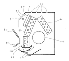
次に、図1ないし図4を参照して、本発明の実施形態について説明する。図1は本発明による空気調和機の室内機の構成を概略的に示す模式図、図2は空気調和機の制御系を概略的に示すブロック図である。
【0018】
これによると、この空気調和機は、室内機側の制御回路1と室外機側の制御回路2とを備えている。各制御回路1,2は、例えばマイクロコンピュータからなり、室温コントロールに必要な制御を行い、また、クリーン運転時には、必要に応じて室内機内部の乾燥運転を行った後、室温または室内湿度に応じて電気式空気清浄ユニットの通電電圧を制御して発生オゾン量を可変して室内機内部を殺菌、脱臭する第1クリーンモードの運転を行い、さらにマイナスイオン発生部によってもオゾンを発生させて室内機内部を殺菌、脱臭する第2のクリーンモードでの運転を行う。
【0019】
この実施形態において、室内機は壁掛け型で、そのハウジングの前面から上面にかけて空気吸入口が形成されており、ハウジング前面の空気吸入口には、前面開閉パネル3aが設けられている。また、前面開閉パネル3aの下方で空気吹き出し口寄りの位置には、マルチパネル(補助開閉パネル)3bが設けられている。
【0020】
マルチパネル3bは、上端側を基点として下端側が開き、空気吹き出し口から吹き出された空気を室内機の内部に戻すショートサーキットを形成する。前面パネル部3aの上部および室内機上面には、開閉パネルを有しない常時開状態の空気吸入口3c,3dが設けられている。
【0021】
室内機ハウジングの下方には空気吹き出し口が設けられており、その内部には空気の吹き出し方向を上下方向に変えるための上下風向板部4と、左右方向に変えるための図示しない左右風向板とが設けられている。
【0022】
また、室内機の空気吸入口と空気吹き出し口とを結ぶ空気通路内には、ハウジングの背面側から前面側にかけてΛ(ラムダ)型とした室内熱交換器5a,5b,5cと、正逆回転可能なクロスフローファンからなる室内送風ファン6とが配置されている。
【0023】
常時開状態の空気吸入口3c,3dのうちの空気吸入口3cの背面で、室内熱交換器5bの前には電気式空気清浄ユニットとしての電気集塵部7が配置されている。また、空気吹き出し口付近には吹き出し空気にマイナスイオンを含ませるマイナスイオン発生部8が配置されている。
【0024】
また、室内機の内部には、室温を検出する室温センサ9および室内の湿度を検出する湿度センサ10が配置されている。この例において、室温センサ9および湿度センサ10は、空気吸入口3cの背面側に設けられているが、その位置は任意に選択できる。
【0025】
室内機の他の構成として、ハウジングの前面側には、リモコン11からのリモコン信号を受信する受信部および運転状態を表示する本体表示部12が備えられている。また、室内熱交換器5cの下部には、同熱交換器から滴下する凝縮水を受けて室外に排出するためのドレンパン13が備えられている。図示しないが、室内熱交換器5aの下部にもドレンパンが設けられている。なお、室外機の方には、室内熱交換器5a,5b,5cとともに冷凍サイクルを構成する四方弁14および圧縮機15と、室外ファン16とが設けられている。
【0026】
室内機の制御回路1は、リモコン11の設定操作に応じて開閉パネル3a、マルチパネル3b、上下風向板部4および室内送風ファン6などを制御する一方、室温と設定温度の差に応じた圧縮機の運転コードなどを室外機側の制御回路2に送信するとともに、その制御回路2との間で室温コントロールに必要な信号の授受を行い、また、リモコン11の設定操作などに応じて電気集塵部7およびマイナスイオン発生部8を制御する。
【0027】
そのため、制御回路1は、リモコン信号を判定する判定部1aおよび当該空気調和機の運転状態を判定する状態判定部1c,図3および図4に示すルーチンの実行時に用いるタイマ1b,記憶部1d,カウンタ部1e,室内送風ファン6の回転数を検出する回転数検出部1fおよび電気集塵部7の通電電圧を制御する空清通電可変部1gを備えている。
【0028】
また、室外機の制御回路2は、四方弁14および室外ファン16を制御するために室内機側からの運転モードなどを判別する運転モード判定部2aと、圧縮機15を制御する圧縮機制御部2bとを備えている。
【0029】
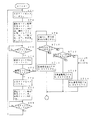
次に、本発明の動作を図3および図4のフローチャートを参照して説明する。まず、リモコン11によって所定設定操作が行われると、その設定操作に応じて室内機側の制御回路1および室外機側の制御回路2は室温コントロールに必要な制御を行い、あるいはその室温コントロールなどのための運転を停止する。
【0030】
その運転において、制御回路1は設定操作の運転モードにしたがって開閉パネル3a,マルチパネル3bを自動的に開閉制御し、上下風向板部4を自動的に方向制御し、室内送風ファン6を回転制御し、また、電気集塵部7およびマイナスイオン発生部8を制御する。
【0031】
このようにして運転が行われているとき、あるいは運転が停止されているときに、リモコン11から発信されたクリーン運転信号を受信すると、制御回路1は図3および図4に示すルーチンを実行する。なお、以下の説明でのタイマ時間,室内送風ファンや圧縮機の回転数,ステップの繰り返し回数などは、あくまで一例としてのものである。
【0032】
まず、タイマ1bの3分タイマをスタートし(ステップST1)、運転モードを暖房に切り替え、圧縮機15の運転コード0(回転数0rps)を発信し、室内送風ファン6のファン回転数を900rpmと弱めの送風とし、開閉パネル3aおよびマルチパネル3bを開状態とし、上下風向板部4を水平方向にして、本体表示部11にクリーン運転の表示を行う(ステップST2)。この場合、室外機側では、暖房運転であることを運転モード判定部2aで判定して四方弁14を暖房サイクル側に切り替える。
【0033】
圧縮機15を停止したままでの暖房運転(つまり暖かめの送風運転に近い運転)を3分間維持して室内機内部の乾燥運転を行う。なお、室内送風ファン6が弱めの送風であることから、室内環境の悪化を招くこともない。
【0034】
3分タイマがタイムアップすると、ステップST3からステップST4に進み、カウンタ部1eの暖房0コード発信カウンタをインクリメントする(カウント値に+1を加える)。この場合、最初の暖房0コード発信であることから、その暖房0コード発信カウンタは1となる。
【0035】
続いて、暖房0コード発信カウンタの値が所定値(例えば4)であるか否かを判断する(ステップST5)。カウンタ値が4でなければ、タイマ1bの2分タイマをスタートし(ステップST6)、運転モードを暖房とし、圧縮機15の運転コードを8(例えば回転数39rps)とし、室内送風ファン6のファン回転数を900rpmとする(ステップST7)。この場合、室外機側では、圧縮機制御部2bで圧縮機15を例えば回転数39rpsに制御し、圧縮機15の運転に伴って室外ファン16を回転制御することになる。
【0036】
2分タイマがタイムアップしたか否かを判断し(ステップST8)、そのタイムアップによりステップST1に戻って上述した処理を繰り返す。このように、圧縮機15を0コード運転とした送風運転に近い暖房運転を3分間行い、しかる後、圧縮機15を8コード運転とした弱めの暖房運転を2分間行い、しかもその両方の運転を少なくとも3回連続して行うことにより、室内機内部を十分に乾燥させることができ、例えばドレンパン13に凝縮水が溜っていたとしても、その凝縮水を蒸発させて室内機内部を乾燥させることができる。
【0037】
暖房0コード発信カウンタの値が4になると、ステップST5からステップST9に進み、室温センサ9による検出信号により室温Trを検出するとともに、湿度センサ10による検出信号により湿度(相対湿度)Rhを検出する。
【0038】
そして、室温Trが25℃以上であるか、または湿度Rhが80%以上であるかを判断し(ステップST10)、そのいずれか一方でも、高い条件を満足しているときには、空清通電可変部1gに電気集塵部7の通電電圧Vを通常時の定格値(例えば4.2kV)よりかなり高い値(例えば6.0kV)に設定する(ステップST11)。
【0039】
これに対して、室温Trが25℃以上でなく、または湿度Rhが80%以上高くなければ、ステップST10からステップST12に進み、室温Trが15℃以上、25℃未満とそれほど高くないか、または度Rhが60%以上、80%未満とそれほど高くないか否かを判断する。
【0040】
室温Trあるいは湿度Rhの一方でもその高くない条件を満足しているときには、電電気集塵部7の通電電圧Vを6.0kVより低く、通常時の定格値より高めの値(例えば5.0kV)に設定する(ステップST13)。
【0041】
さらに、室温Trまたは湿度Rhが低く、室温Trが15℃未満であり、または湿度Rhが60%未満であるときには、ステップST12からステップST14に進み、電気集塵部7の通電電圧Vを通常時の定格値(例えば4.2kV)に設定する。
【0042】
このように、室温Trが高いほど、または湿度Rhが高いほど、電気集塵部7の通電電圧Vを高くすることにより、オゾンが分解し易い高室温または高湿度の条件下でも殺菌、脱臭が効果的に行われ、殺菌、脱臭に要するクリーン運転時間を短縮することができる。
【0043】
続いて、室内送風ファン6を停止し(ステップST15)、運転モード設定を送風に決定し、開閉パネル3aを全閉状態とし、マルチパネル3bを開状態とし、上下風向板部4を上向きとし、電気集塵部7をオンとし、マイナスイオン発生部8をオフとする(ステップST16)。
【0044】
そして、タイマ1bの10分タイマをスタートし(ステップST17)、室内送風ファン6を5秒間運転するとともに、600rpmの正回転とし(ステップST18)、しかる後、室内送風ファン6を1分間オフとする(ステップST19)。そして、10分タイマがタイムアップするまで、室内送風ファン6を5秒運転、1分停止を繰り返す(ステップST20)。
【0045】
この第1クリーンモードでの運転により、前面開閉パネル3aを閉じてほぼ密閉状態とした室内機内部には電気集塵部7の通電により発生したオゾンが確実に室内機内部に行き渡ることになる。また、マルチパネル3bが開状態であることから、マルチパネル3bによって形成されたショートサーキット作用により漏れオゾンが室内機内部に吸入されることになり、室内機内部の殺菌、脱臭が効率的、効果的に行われる。
【0046】
続いて、10分タイマがタイムアップすると、ステップST20からステップST21に進み、室内送風ファン6を停止し、マイナスイオン発生部8をオンにしてオゾンを発生し、マルチパネル部3cも閉じて、第2クリーンモードでの運転に入る。
【0047】
この第2クリーン運転では、まず、タイマ1bの10分タイマをスタートし(ステップST22)、室内送風ファン6の回転数を回転数検出部1fで検出し、回転数が0rpmであるか否かを判断する(ステップST23)。この場合、室内送風ファン6の位置センサからの検出信号により回転数を検出するとよい。
【0048】
室内送風ファン6の回転数が0rpmになり完全に停止すると、1秒間待機し(ステップST24)、しかる後に室内送風ファン6を逆回転し(空気吸い込み方向とし)、かつ、その逆回転数を920rpm程度とする(ステップST25)。これは、室内送風ファン6が完全に停止しないまま、逆回転しようとすると、室内送風ファン6の制御が適切に行われないことがあるためである。
【0049】
室内送風ファン6の逆回転により、ほぼ密閉状態に近い室内機内部にはマイナスイオン発生部8によって発生したオゾンも行き渡らせることができ、しかもそのオゾンが室内機外(室内)への拡散が抑えられる。
【0050】
続いて、室内送風ファン6の逆回転中に、リモコン11によって他の機能を設定する信号が入力されたか否かを判断し(ステップST26)、その設定操作が行われていないときには、運転停止信号が入力したか否かを判断する(ステップST27)。なお、その他の機能とは、例えば運転開始信号、除湿信号、空清運転信号あるいはクリーン運転信号などである。
【0051】
運転停止の設定操作も行われていないときには、10分タイマがタイムアップしているか否かを判断し(ステップST28)、10分が経過していなければステップST26に戻り、上述した判断処理を繰り返し、10分が経過すると、クリーン運転を停止し(ステップST29)、ルーチンを終了する。
【0052】
このように、室内送風ファン6の逆回転は最大で10分間継続されることになり、室内機の上部に配置した電気集塵部7によって発生したオゾンだけなく、室内機の下部(この例では空気吹き出し口内)に配置したマイナスイオン発生部8によって発生したオゾンも利用して室内機内部の隅々、特に背面側の熱交換器6aや空気吹き出し口付近および空気通路の殺菌、脱臭を効果的に行うことができる。
【0053】
なお、10分タイマがタイムアップするまでの間に、リモコン11によって運転停止操作が行われた場合にはステップST27からステップST29に進み、クリーン運転を停止し、当該ルーチンを終了する。
【0054】
また、リモコン11によって他の機能を設定する信号が入力された場合にはステップST26からステップST30に進み電気集塵部7をオフにする。なお、他の機能の信号としては、運転開始信号、除湿信号、空清信号、ワンタッチ切タイマ信号およびクリーン信号(再入力)などである。また、その他の機能の設定操作によっては、マイナスイオン発生部8もオフにしてもよい。
【0055】
続いて、室内送風ファン6を停止制御し(ステップST31)、室内送風ファン6の回転数を検出し、室内送風ファン6の回転数が0rpmになると(ステップST32)、1秒間待機し(ステップST33)、しかる後に当該設定されている他の機能の動作処理を実行する一方(ステップST34)、クリーン運転を終了する(ステップST29)。
【0056】
なお、クリーン運転がその途中でリモコン11からの他の機能設定などにより強制的に終了しない限り、クリーン運転終了時には自動的にクリーン運転直前の運転モードに戻す。これにより、再度リモコン11による設定操作の手間が省け、クリーン運転直前の運転モードの設定状態を覚えていなくともよい。
【0057】
【発明の効果】
以上説明したように、本発明によれば、電気集塵部およびマイナスイオン発生部からオゾンを発生させて室内機内部の殺菌、脱臭を行うクリーン運転を行う場合、第1クリーンモードでは、空気吹き出し口と補助開閉パネルとの間に空気のショートサーキットが形成される状態として、電気集塵部によってオゾンを発生させ、第1クリーンモード終了後の第2クリーンモードでは、補助開閉パネルを閉じて、マイナスイオン発生部によってもオゾンを発生させ、しかも室温および室内湿度を検出して、その検出室温あるいは湿度に応じて電気集塵部の通電電圧を可変し、特にオゾンが分解し易い高室温または高湿度の条件下では発生オゾン量を多くするようにしたことにより、室内が高温・高湿環境である場合においても、オゾンによる殺菌,脱臭効果を高めて、クリーン運転時間を短縮することができる。
【0058】
また、クリーン運転に先だって、所定時間暖房運転を行うことにより、例えば室内機のドレンパンに溜っている凝縮水が蒸発されるため、室内機内部の殺菌、脱臭がさらに効果の向上が図れられる。
【図面の簡単な説明】
【図1】本発明の空気調和機の室内機の構成を説明するための模式的な断面図。
【図2】上記空気調和機の制御系を示す概略的ブロック図。
【図3】本発明の動作説明用フローチャート図。
【図4】本発明の動作説明用フローチャート図。
【符号の説明】
1 室内機側制御回路
1a 判定部
1b タイマ
1c 状態判定部
1d 記憶部
1e カウンタ部
1f 回転数検出部
1g 空清通電可変部
2 室外機側制御回路
2a 運転モード判定部
2b 圧縮機制御部
3a 開閉パネル
3b マルチパネル(補助開閉パネル)
3c,3d 常開型空気吸入口
4 上下風向板
5a,5b,5c 室内熱交換器
6 室内送風ファン
7 電気集塵部
8 マイナスイオン発生部
9 室温センサ
10 湿度センサ
11 リモコン
12 本体表示部
13 ドレンパン
14 四方弁
15 圧縮機
16 室外ファン[0001]
BACKGROUND OF THE INVENTION
The present invention relates to an air conditioner, more particularly, sterilization of the inside of the indoor unit by the ozone, but about the cleaning operation is capable air conditioner that performs deodorization.
[0002]
[Prior art]
In the recent field of air conditioners, various pursuits for comfort by adding various functions have been proposed. As an example, an electric dust collector (electric air cleaning unit) is installed in the indoor unit, and fine dust such as cigarette smoke is charged at a high voltage to collect dust, collecting air dirt, and improving the indoor environment. There is something that is intended to.
[0003]
By the way, when cooling operation or dry operation (weak cooling operation) is performed, condensed water adheres to the indoor heat exchanger, and the condensed water is discharged to the outside through the drain pan. May remain in indoor heat exchangers and drain pans.
[0004]
If dust or the like adheres to the residual condensed water, various germs such as molds propagate inside the indoor unit or generate an unpleasant odor. In order to suppress the unpleasant odor, clean operation is performed in which ozone is generated by an electric dust collector to sterilize the interior of the indoor unit.
[0005]
[Problems to be solved by the invention]
However, the sterilization and deodorization effect by ozone is easily affected by the temperature and humidity in the room. In general, ozone is easily decomposed under high temperature and high humidity conditions, and its sterilization and deodorizing effects are reduced.
[0006]
Therefore, when the room is hot and humid, it takes a long time for clean operation time to generate ozone in order to obtain the sterilization and deodorization effect by ozone, which affects the original air conditioning operation. The indoor environment may be deteriorated.
[0007]
Therefore, an object of the present invention is to improve the sterilization and deodorizing effects by ozone and shorten the clean operation time even when the room is in a high temperature and high humidity environment.
[0008]
[Means for Solving the Problems]
In order to solve the above-described problems, the present invention provides a room in which a heat exchanger and an indoor fan are arranged in an air passage connecting an air inlet and an air outlet provided at a position below the air inlet. An electric dust collector is disposed between the air inlet and the heat exchanger, a negative ion generator is disposed in the air outlet, and a controller controls the electric dust collector and the electric dust collector. In an air conditioner capable of clean operation with ozone by operating a negative ion generator, a short circuit of air is formed in the indoor unit housing at a position between the air inlet and the air outlet. An auxiliary opening / closing panel is provided, and the control unit opens the auxiliary opening / closing panel between the auxiliary opening / closing panel and the air outlet during the clean operation. In a state where a short circuit of air is formed, after the first clean mode is executed for a predetermined time period in which the indoor fan is operated while ozone is generated by the electric dust collector, the auxiliary open / close panel is closed to generate the negative ions. The second clean mode in which the indoor fan is rotated in a reverse direction while ozone is generated by the vessel is performed for a predetermined time.
[0009]
In the present invention, the energization voltage of the electrostatic precipitator in the first clean mode is set to a higher value than the normal rated value as the room temperature or the room humidity is higher, and the room temperature or the room humidity is lower. The setting is set to a value close to the normal rated value.
[0010]
As described above, in the first clean mode, ozone is generated by the electric dust collector as a state where a short circuit of air is formed between the air outlet and the auxiliary opening / closing panel , and the electric dust collector The energized voltage is increased at higher room temperature or higher humidity to increase the amount of ozone generated. The ozone mainly sterilizes the heat exchanger on the front side of the indoor unit body and the indoor fan, causing odors. Mold is removed.
[0011]
Therefore, it is not necessary to continue the clean operation for a long time even in a room environment with high room temperature or high humidity. In addition, the short circuit of air makes it difficult for ozone to leak into the room, improving the utilization efficiency of ozone and effectively sterilizing the drain pan near the auxiliary opening / closing panel.
[0012]
Further, in the second clean mode after the end of the first clean mode, the auxiliary open / close panel is closed and ozone is also generated by the negative ion generator, so that the air passage mainly on the air inlet side by the ozone, The indoor fan and the heat exchanger on the back side are sterilized.
[0013]
Although the clean operation may be performed in the cooling mode or the heating mode, from the viewpoint of energy saving, the first clean mode and the second clean mode are preferably performed in the air blowing mode.
[0014]
In addition, prior to executing the first clean mode, it is preferable to perform a heating operation for a predetermined time to dry the interior of the indoor unit. As a result, when clean operation is performed, the interior of the indoor unit is dried, and since there is almost no moisture that lowers the sterilization effect of ozone, sterilization by ozone generated by the electrostatic precipitator and the negative ion generator is effective. Done.
[0015]
At the time of the drying operation in the heating mode, the open / close panel and the auxiliary open / close panel provided at the air suction port may be opened, and the vertical wind direction plate provided at the air outlet may be in a horizontal state. According to this, the inside of the indoor unit is quickly dried, and the total clean operation time relating to sterilization inside the indoor unit can be shortened.
[0016]
In addition, when the clean operation is selected while operating in the predetermined operation mode, it is preferable to return the air conditioner to the operation mode immediately before the clean operation after the clean operation is completed. According to this, it becomes unnecessary for the user to operate the remote controller again after the end of the clean operation, and it is not necessary to remember the setting state of the operation mode immediately before the clean operation.
[0017]
DETAILED DESCRIPTION OF THE INVENTION
Next, an embodiment of the present invention will be described with reference to FIGS. FIG. 1 is a schematic diagram schematically showing the configuration of an indoor unit of an air conditioner according to the present invention, and FIG. 2 is a block diagram schematically showing a control system of the air conditioner.
[0018]
According to this, this air conditioner is provided with a
[0019]
In this embodiment, the indoor unit is a wall-mounted type, and an air suction port is formed from the front surface to the top surface of the housing, and a front opening /
[0020]
The multi-panel 3b forms a short circuit that opens from the upper end side to the lower end side and returns the air blown from the air outlet to the interior of the indoor unit. Air inlets 3c and 3d that are normally open and do not have an open / close panel are provided on the upper portion of the
[0021]
An air outlet is provided below the indoor unit housing. Inside the air outlet is an up / down airflow
[0022]
Further, in the air passage connecting the air intake port and the air outlet port of the indoor unit, a Λ (lambda) type
[0023]
An electric
[0024]
Further, a
[0025]
As another configuration of the indoor unit, a reception unit that receives a remote control signal from the remote controller 11 and a main body display unit 12 that displays an operation state are provided on the front side of the housing. A drain pan 13 for receiving condensed water dripping from the heat exchanger and discharging it outside the room is provided at the lower part of the
[0026]
The
[0027]
Therefore, the
[0028]
The outdoor
[0029]
Next, the operation of the present invention will be described with reference to the flowcharts of FIGS. First, when a predetermined setting operation is performed by the remote controller 11, the
[0030]
In the operation, the
[0031]
When the operation is performed in this way or when the operation is stopped, when the clean operation signal transmitted from the remote controller 11 is received, the
[0032]
First, the 3-minute timer of the
[0033]
The heating operation with the compressor 15 stopped (that is, the operation close to the warm air blowing operation) is maintained for 3 minutes to perform the drying operation inside the indoor unit. In addition, since the
[0034]
When the 3-minute timer expires, the process proceeds from step ST3 to step ST4, and the
[0035]
Subsequently, it is determined whether or not the value of the
[0036]
It is determined whether or not the 2-minute timer has expired (step ST8), and the process returns to step ST1 due to the time-up and the above-described processing is repeated. Thus, the heating operation close to the air blowing operation with the compressor 15 as the 0 code operation is performed for 3 minutes, and then the weak heating operation with the compressor 15 as the 8 code operation is performed for 2 minutes, and both of these operations are performed. By continuously performing at least three times, the interior of the indoor unit can be sufficiently dried. For example, even if condensed water is accumulated in the drain pan 13, the condensed water is evaporated to dry the interior of the indoor unit. Can do.
[0037]
When the value of the
[0038]
Then, it is determined whether the room temperature Tr is 25 ° C. or higher or the humidity Rh is 80% or higher (step ST10). If any one of the conditions satisfies a high condition, the emptying
[0039]
On the other hand, if the room temperature Tr is not 25 ° C. or higher or the humidity Rh is not higher than 80%, the process proceeds from step ST10 to step ST12, and the room temperature Tr is not so high as 15 ° C. or higher and lower than 25 ° C. It is determined whether the degree Rh is not so high as 60% or more and less than 80%.
[0040]
When either the room temperature Tr or the humidity Rh satisfies the condition that is not high, the energization voltage V of the
[0041]
Further, when the room temperature Tr or the humidity Rh is low, the room temperature Tr is less than 15 ° C., or the humidity Rh is less than 60%, the process proceeds from step ST12 to step ST14, and the energization voltage V of the
[0042]
In this way, the higher the room temperature Tr or the higher the humidity Rh, the higher the energization voltage V of the
[0043]
Subsequently, the
[0044]
Then, a 10 minute timer of the
[0045]
By the operation in the first clean mode, the ozone generated by energization of the
[0046]
Subsequently, when the 10-minute timer expires, the process proceeds from step ST20 to step ST21, the
[0047]
In the second clean operation, first, a 10-minute timer of the
[0048]
When the rotation speed of the indoor
[0049]
By reverse rotation of the
[0050]
Subsequently, during the reverse rotation of the
[0051]
When the operation for setting the operation stop is not performed, it is determined whether or not the 10-minute timer has expired (step ST28). If 10 minutes have not elapsed, the process returns to step ST26 and the above-described determination process is repeated. When 10 minutes have elapsed, the clean operation is stopped (step ST29), and the routine is terminated.
[0052]
Thus, the reverse rotation of the
[0053]
If the operation stop operation is performed by the remote controller 11 before the 10-minute timer expires, the process proceeds from step ST27 to step ST29, the clean operation is stopped, and the routine ends.
[0054]
When a signal for setting other functions is input from the remote controller 11, the process proceeds from step ST26 to step ST30, and the electrostatic
[0055]
Subsequently, the
[0056]
Note that unless the clean operation is forcibly terminated by other function settings from the remote controller 11 or the like, the operation mode immediately before the clean operation is automatically restored at the end of the clean operation. Thereby, the trouble of setting operation by the remote controller 11 is saved again, and the setting state of the operation mode immediately before the clean operation may not be remembered.
[0057]
【The invention's effect】
As described above, according to the present invention, in the first clean mode , in the first clean mode, air is blown out when ozone is generated from the electrostatic precipitator and the negative ion generator to sterilize and deodorize the interior of the indoor unit. As a state where a short circuit of air is formed between the mouth and the auxiliary open / close panel, ozone is generated by the electrostatic precipitator, and in the second clean mode after the completion of the first clean mode, the auxiliary open / close panel is closed, The negative ion generator also generates ozone, detects the room temperature and room humidity, and varies the energizing voltage of the electrostatic precipitator according to the detected room temperature or humidity. By increasing the amount of ozone generated under humidity conditions, sterilization with ozone even when the room is in a high-temperature and high-humidity environment To enhance the deodorizing effect, it is possible to shorten the cleaning operation time.
[0058]
Further, by performing the heating operation for a predetermined time prior to the clean operation, for example, the condensed water accumulated in the drain pan of the indoor unit is evaporated, so that the effect of sterilization and deodorization inside the indoor unit can be further improved.
[Brief description of the drawings]
Schematic cross-sectional view for explaining a chamber in machine configuration of the air conditioner of the present invention; FIG.
FIG. 2 is a schematic block diagram showing a control system of the air conditioner.
FIG. 3 is a flowchart for explaining the operation of the present invention.
FIG. 4 is a flowchart for explaining the operation of the present invention.
[Explanation of symbols]
DESCRIPTION OF
3c, 3d Normally open
Claims (6)
上記室内機ハウジングには、上記空気吸入口と上記空気吹き出し口との間の位置に空気のショートサーキットを形成し得る補助開閉パネルが設けられており、
上記制御部は、上記クリーン運転時、上記補助開閉パネルを開いて上記補助開閉パネルと上記空気吹き出し口との間に空気のショートサーキットが形成される状態として上記電気集塵器によりオゾンを発生させながら上記室内送風ファンを動作させる第1クリーンモードを所定時間実行した後、上記補助開閉パネルを閉じて上記マイナスイオン発生器によりオゾンを発生させながら上記室内送風ファンを逆回転させる第2クリーンモードを所定時間実行することを特徴とする空気調和機。An air passage connecting the air inlet and an air outlet provided at a position below the air inlet includes an indoor unit housing in which a heat exchanger and an indoor fan are disposed, and the air inlet and the air An electric dust collector is disposed between the heat exchanger, a negative ion generator is disposed in the air outlet , and ozone is generated by operating the electric dust collector and the negative ion generator by a control unit. In an air conditioner that can be operated cleanly,
The indoor unit housing is provided with an auxiliary opening / closing panel capable of forming a short circuit of air at a position between the air inlet and the air outlet.
In the clean operation, the control unit opens the auxiliary opening / closing panel and generates ozone by the electric dust collector in a state where a short circuit of air is formed between the auxiliary opening / closing panel and the air outlet. The first clean mode for operating the indoor blower fan is executed for a predetermined time, and then the second clean mode for reversely rotating the indoor blower fan while closing the auxiliary open / close panel and generating ozone by the negative ion generator. An air conditioner that is executed for a predetermined time.
Priority Applications (1)
| Application Number | Priority Date | Filing Date | Title |
|---|---|---|---|
| JP2002178021A JP4277166B2 (en) | 2002-06-19 | 2002-06-19 | Air conditioner |
Applications Claiming Priority (1)
| Application Number | Priority Date | Filing Date | Title |
|---|---|---|---|
| JP2002178021A JP4277166B2 (en) | 2002-06-19 | 2002-06-19 | Air conditioner |
Publications (3)
| Publication Number | Publication Date |
|---|---|
| JP2004020117A JP2004020117A (en) | 2004-01-22 |
| JP2004020117A5 JP2004020117A5 (en) | 2005-10-13 |
| JP4277166B2 true JP4277166B2 (en) | 2009-06-10 |
Family
ID=31175865
Family Applications (1)
| Application Number | Title | Priority Date | Filing Date |
|---|---|---|---|
| JP2002178021A Expired - Fee Related JP4277166B2 (en) | 2002-06-19 | 2002-06-19 | Air conditioner |
Country Status (1)
| Country | Link |
|---|---|
| JP (1) | JP4277166B2 (en) |
Cited By (1)
| Publication number | Priority date | Publication date | Assignee | Title |
|---|---|---|---|---|
| CN102483248A (en) * | 2009-09-10 | 2012-05-30 | 夏普株式会社 | Air conditioner |
Families Citing this family (11)
| Publication number | Priority date | Publication date | Assignee | Title |
|---|---|---|---|---|
| JP5180489B2 (en) * | 2007-02-20 | 2013-04-10 | 三洋電機株式会社 | Air conditioner |
| CN105333567B (en) * | 2014-08-13 | 2018-09-18 | 戴若夫 | Haze fresh air system and its control method are removed based on electrostatic precipitation filter |
| CN105485837A (en) * | 2015-12-16 | 2016-04-13 | 青岛海尔空调器有限总公司 | Control method for degerming inner part of air conditioner |
| JP2020200966A (en) * | 2019-06-06 | 2020-12-17 | 三菱重工サーマルシステムズ株式会社 | Method for sterilizing air conditioner, air conditioner and device for controlling air conditioner |
| CN113924166B (en) * | 2019-06-10 | 2024-04-02 | 三菱电机株式会社 | Dust collector and air conditioner with same |
| CN113685981B (en) * | 2020-05-19 | 2023-06-09 | 海信空调有限公司 | Air conditioner and control method |
| CN111594917A (en) * | 2020-06-01 | 2020-08-28 | 宁波奥克斯电气股份有限公司 | Air conditioner sterilization method, sterilization device and air conditioner |
| CN112594895B (en) * | 2020-11-19 | 2022-08-09 | 珠海格力电器股份有限公司 | Intelligent regulation and control method and system for temperature of outdoor unit |
| CN112696805B (en) * | 2020-12-29 | 2022-04-05 | 珠海格力电器股份有限公司 | Method and device for controlling air conditioning equipment and processor |
| CN114001431B (en) * | 2021-12-31 | 2022-03-11 | 北京福乐云数据科技有限公司 | Active fog ion generator for indoor environment disinfection |
| CN116026008A (en) * | 2023-01-05 | 2023-04-28 | 宁波奥克斯电气股份有限公司 | Sterilization control method and device for air conditioner and air conditioner |
Family Cites Families (6)
| Publication number | Priority date | Publication date | Assignee | Title |
|---|---|---|---|---|
| JPH05141692A (en) * | 1991-11-19 | 1993-06-08 | Daikin Ind Ltd | Air conditioner |
| JP3413232B2 (en) * | 1993-03-19 | 2003-06-03 | 東芝キヤリア株式会社 | Air conditioner |
| JP4323019B2 (en) * | 1999-08-31 | 2009-09-02 | 東芝キヤリア株式会社 | Air conditioner indoor unit |
| JP2002061916A (en) * | 2000-08-11 | 2002-02-28 | Fujitsu General Ltd | Air conditioner |
| JP2002065828A (en) * | 2000-08-23 | 2002-03-05 | Toto Ltd | Air cleaner |
| JP2002147790A (en) * | 2000-11-06 | 2002-05-22 | Fujitsu General Ltd | Air conditioner |
-
2002
- 2002-06-19 JP JP2002178021A patent/JP4277166B2/en not_active Expired - Fee Related
Cited By (2)
| Publication number | Priority date | Publication date | Assignee | Title |
|---|---|---|---|---|
| CN102483248A (en) * | 2009-09-10 | 2012-05-30 | 夏普株式会社 | Air conditioner |
| CN102483248B (en) * | 2009-09-10 | 2014-07-23 | 夏普株式会社 | Air conditioner |
Also Published As
| Publication number | Publication date |
|---|---|
| JP2004020117A (en) | 2004-01-22 |
Similar Documents
| Publication | Publication Date | Title |
|---|---|---|
| JP4297625B2 (en) | Air conditioner | |
| JP2004020118A (en) | Control method for air conditioning machine | |
| JP4396688B2 (en) | Air conditioner and operation method thereof | |
| JP3413232B2 (en) | Air conditioner | |
| JP4277166B2 (en) | Air conditioner | |
| KR0182545B1 (en) | Deodorizer | |
| JP4003101B2 (en) | Control method and apparatus for air conditioner | |
| JP4476514B2 (en) | Air conditioner | |
| JP3576149B2 (en) | Air conditioner | |
| JP2002349891A (en) | Air conditioner | |
| JP2003247740A (en) | Control method for air conditioner | |
| JP4182322B2 (en) | Control method of air conditioner | |
| JP2003014334A (en) | Air conditioner and drying operation method of indoor unit thereof | |
| KR20040055628A (en) | Method for controlling air conditioner | |
| JP4632013B2 (en) | Control method of air conditioner | |
| JP5462517B2 (en) | Device control method and air conditioner employing the same | |
| JP2003106600A (en) | Control method for air conditioner | |
| KR20100083913A (en) | An air conditioner and control method thereof | |
| JP4484011B2 (en) | Control method of air conditioner | |
| JP4632014B2 (en) | Control method of air conditioner | |
| JP2002228227A (en) | Method for controlling air conditioner | |
| JP3942910B2 (en) | Air conditioner | |
| JP2004116860A (en) | Air conditioner | |
| JPH11159832A (en) | Controller for air conditioner | |
| JP4539797B2 (en) | Control method of air conditioner |
Legal Events
| Date | Code | Title | Description |
|---|---|---|---|
| A521 | Request for written amendment filed |
Free format text: JAPANESE INTERMEDIATE CODE: A523 Effective date: 20050603 |
|
| A621 | Written request for application examination |
Free format text: JAPANESE INTERMEDIATE CODE: A621 Effective date: 20050603 |
|
| A977 | Report on retrieval |
Free format text: JAPANESE INTERMEDIATE CODE: A971007 Effective date: 20070411 |
|
| A131 | Notification of reasons for refusal |
Free format text: JAPANESE INTERMEDIATE CODE: A131 Effective date: 20070502 |
|
| A521 | Request for written amendment filed |
Free format text: JAPANESE INTERMEDIATE CODE: A523 Effective date: 20070702 |
|
| A131 | Notification of reasons for refusal |
Free format text: JAPANESE INTERMEDIATE CODE: A131 Effective date: 20071017 |
|
| A521 | Request for written amendment filed |
Free format text: JAPANESE INTERMEDIATE CODE: A523 Effective date: 20071217 |
|
| A131 | Notification of reasons for refusal |
Free format text: JAPANESE INTERMEDIATE CODE: A131 Effective date: 20080220 |
|
| A521 | Request for written amendment filed |
Free format text: JAPANESE INTERMEDIATE CODE: A523 Effective date: 20080418 |
|
| TRDD | Decision of grant or rejection written | ||
| A01 | Written decision to grant a patent or to grant a registration (utility model) |
Free format text: JAPANESE INTERMEDIATE CODE: A01 Effective date: 20090212 |
|
| A01 | Written decision to grant a patent or to grant a registration (utility model) |
Free format text: JAPANESE INTERMEDIATE CODE: A01 |
|
| A61 | First payment of annual fees (during grant procedure) |
Free format text: JAPANESE INTERMEDIATE CODE: A61 Effective date: 20090225 |
|
| FPAY | Renewal fee payment (event date is renewal date of database) |
Free format text: PAYMENT UNTIL: 20120319 Year of fee payment: 3 |
|
| FPAY | Renewal fee payment (event date is renewal date of database) |
Free format text: PAYMENT UNTIL: 20120319 Year of fee payment: 3 |
|
| FPAY | Renewal fee payment (event date is renewal date of database) |
Free format text: PAYMENT UNTIL: 20130319 Year of fee payment: 4 |
|
| S531 | Written request for registration of change of domicile |
Free format text: JAPANESE INTERMEDIATE CODE: R313532 |
|
| R350 | Written notification of registration of transfer |
Free format text: JAPANESE INTERMEDIATE CODE: R350 |
|
| LAPS | Cancellation because of no payment of annual fees |