JP4276076B2 - Method and apparatus for forming foam - Google Patents
Method and apparatus for forming foam Download PDFInfo
- Publication number
- JP4276076B2 JP4276076B2 JP2003542703A JP2003542703A JP4276076B2 JP 4276076 B2 JP4276076 B2 JP 4276076B2 JP 2003542703 A JP2003542703 A JP 2003542703A JP 2003542703 A JP2003542703 A JP 2003542703A JP 4276076 B2 JP4276076 B2 JP 4276076B2
- Authority
- JP
- Japan
- Prior art keywords
- foam
- web
- headbox
- head box
- fibers
- Prior art date
- Legal status (The legal status is an assumption and is not a legal conclusion. Google has not performed a legal analysis and makes no representation as to the accuracy of the status listed.)
- Expired - Lifetime
Links
Images


Classifications
-
- D—TEXTILES; PAPER
- D21—PAPER-MAKING; PRODUCTION OF CELLULOSE
- D21F—PAPER-MAKING MACHINES; METHODS OF PRODUCING PAPER THEREON
- D21F11/00—Processes for making continuous lengths of paper, or of cardboard, or of wet web for fibre board production, on paper-making machines
- D21F11/002—Processes for making continuous lengths of paper, or of cardboard, or of wet web for fibre board production, on paper-making machines by using a foamed suspension
-
- D—TEXTILES; PAPER
- D21—PAPER-MAKING; PRODUCTION OF CELLULOSE
- D21F—PAPER-MAKING MACHINES; METHODS OF PRODUCING PAPER THEREON
- D21F1/00—Wet end of machines for making continuous webs of paper
- D21F1/02—Head boxes of Fourdrinier machines
- D21F1/022—Means for injecting material into flow within the headbox
Abstract
Description
本発明は、フォーム(foam)を形成するための方法及び装置に関する。本発明の方法及び装置はとりわけ、セルロース、ガラス繊維、アラミド、サイザル麻、又は他の類似の繊維材料の種々のウェブ様生成物を形成するのに適している。本発明の方法及び装置は、例えば、種々の自動車のシャシ(chassis; 車台)部品;機械及び装置の囲い込むもの(enclosures);並びに他の非常に多くの用途;において使用するための、複雑な多層積層物又は複合材料を製造するのにとりわけ適している。本発明の方法及び装置は、長い繊維、又は連続ヤーン、連続リボン若しくは連続ネットさえも利用して生成物を製造するのに使用されることを意味している。本発明に関して記述するフォームは、主として水及び界面活性剤から成るフォームを意味する。 The present invention relates to a method and apparatus for forming a foam. The method and apparatus of the present invention is particularly suitable for forming various web-like products of cellulose, glass fiber, aramid, sisal or other similar fiber materials. The method and apparatus of the present invention is complex for use in, for example, various automobile chassis parts; machinery and equipment enclosures; and numerous other applications. It is particularly suitable for producing multilayer laminates or composite materials. The method and apparatus of the present invention is meant to be used to produce products utilizing long fibers, or even continuous yarns, continuous ribbons or even continuous nets. The foam described in connection with the present invention means a foam mainly composed of water and surfactant.
本発明の好ましい具体例による生成物は、ほとんどの場合、以前同じ用途に使用された金属薄板構造物を取り替えることを意味する。なぜなら、それら金属薄板構造物及び他の類似の金属構造物は、錆びるのを避けるために、製造時も使用時も、大変な気配りと維持とが必要とするからである。金属構造物はまた、小さい衝撃によって、単なる審美的変化が生じるか又は塗装面にも損傷が生じるように、小さい衝撃にさえ敏感である。その結果、これらは、とりわけ、それら構造物が腐食性物質にさらされる用途において、さびを発生させる。
上述の用途において、種々の積層物及び複合材料は一層の耐久性があるが、それらの価格は時として、上述の金属薄板構造物の価格よりも僅かに高い。コストが高い理由の1つは、製造技術が複雑であることである。次の例は、自動車のフェンダー(wing; 泥除け)又はボンネットの製法に関する。
The product according to the preferred embodiment of the invention in most cases means replacing the sheet metal structure previously used for the same application. This is because these sheet metal structures and other similar metal structures require a great deal of care and maintenance during manufacture and use in order to avoid rusting. Metal structures are also sensitive to even small impacts, such that a small impact causes only aesthetic changes or damage to the painted surface. As a result, they generate rust, especially in applications where the structures are exposed to corrosive substances.
In the applications described above, the various laminates and composites are more durable, but their prices are sometimes slightly higher than the prices of the sheet metal structures described above. One reason for the high cost is that the manufacturing technology is complex. The following examples relate to the production of automobile wings or bonnets.
自動車のフェンダー又はボンネットの、外に見える部分が、非常に平滑でなければならないことは言うまでもない。他のいずれかの場合の塗装面(ボートの船体は、これのもう1つの例である)は、光を不均一に反射する。このことは、品質が悪く且つ製造精度が悪いことの表れと見なされる。換言すれば、積層物は、類似表面の平滑さを、金属薄板の平滑さのように見せるのに必要である。実際問題として、このことは、製造物が、例えばガラス繊維から造られるとき、非常に微細粒化繊維を使用しなければならないことを意味する。そのような微細粒化繊維の特徴は、それから造られる積層物が、例えば、自動車のフェンダーとして使用されるのに十分耐えられないことである。従って、ガラス繊維のフェンダーは、幾つかの異なる層で造らなければならない。強度及び耐久性が要求されるため、長さが約45〜50mm(それを超えることもあり、それ未満であることもある)の比較的粗い繊維を有する構造用層が存在する必要がある。 It goes without saying that the part of the automobile fender or bonnet that is visible to the outside must be very smooth. The painted surface in any other case (a boat hull is another example of this) reflects light unevenly. This is regarded as an indication of poor quality and poor manufacturing accuracy. In other words, the laminate is necessary to make the smoothness of a similar surface look like the smoothness of a sheet metal. In practice, this means that when the product is made, for example, from glass fibers, very finely divided fibers must be used. A characteristic of such fine-grained fibers is that the laminates made therefrom are not sufficiently resistant to be used, for example, as automobile fenders. Therefore, glass fiber fenders must be made of several different layers. Because strength and durability are required, there must be a structural layer with relatively coarse fibers that is about 45-50 mm in length (sometimes greater or less).
最小の数として、上述の2つの層は、必要な外観と強度とを達成するのに十分であろうが、その製造を自動化すれば、問題が生じる。先ず、そのプロセスは、生成物の形をよく類似するように再生するモールドが必要である。最も簡単な方法は、単品モールド(one-part mould)のみを用意することであろう。先ず、単品モールドの中に表面マットを置き;次いで、樹脂を入れる。この後、補強用マットを敷き、その頂部に樹脂のもう1つの層を横たえ;その後、それら層は一緒に圧延して、あらゆる気泡を取り除く。しかし、樹脂を延ばす工程と気泡を圧延する工程の両方は、視覚によって制御しなければならないように、この種の製法は、全体的に手動となるであろう。このことに加えて、これに類似する積層プロセスは、製造中にガスが発生するため、健康上危険である。 As a minimum, the two layers described above will be sufficient to achieve the required appearance and strength, but problems arise if their manufacture is automated. First, the process requires a mold that regenerates the shape of the product to be very similar. The simplest way would be to have only a one-part mold. First, place the surface mat in a single mold; then put the resin. After this, a reinforcing mat is laid and another layer of resin is placed on top of it; the layers are then rolled together to remove any air bubbles. However, this type of process would be entirely manual, as both the process of extending the resin and the process of rolling the bubbles must be controlled visually. In addition to this, a similar lamination process is a health hazard due to the evolution of gas during manufacturing.
上述の手作業は、当該業界において、モールドの表面層の頂部に樹脂を置き;次いで、該樹脂の頂部に、例えば、補強用マットを敷く;方法によって置き換えられてきた。積層物は、このようにして形成され;次いで、該モールドの他の半分によってプレスされて、該積層物の形状にされる。また、該モールドの他の半分は、両方の層を通して、該樹脂をプレスする。米国特許第5,672,309号明細書は、注入方法であって、表面層が先ずモールド内に配置され、もう1つの層がそれの頂部に配置される該方法を開示する。それら層の1つは、所望の位置に開口を有している。これら2つの重ね合わされた層は、次いで、該モールドの端部が堅く締り始まるように、該モールドの他の半分によって互いにある程度プレスされる。この段階で、モールドが十分に閉じるとき、樹脂が、該モールドの全体に渡って広がり、両方の層に含浸するように、該樹脂は、それら層の一方の中にある穴(hole)であって、該モールドのいずれか半分の中にあるノズルと対応する該穴を通して、それら層の間に注入される。 The above-described manual operations have been replaced by methods in the industry by placing a resin on top of the surface layer of the mold; then laying a reinforcing mat, for example, on the top of the resin; A laminate is formed in this way; it is then pressed into the shape of the laminate by the other half of the mold. The other half of the mold also presses the resin through both layers. U.S. Pat. No. 5,672,309 discloses an injection method in which a surface layer is first placed in a mold and another layer is placed on top of it. One of the layers has an opening at the desired location. These two superimposed layers are then pressed to some extent by the other half of the mold so that the ends of the mold begin to tighten tightly. At this stage, when the mold is sufficiently closed, the resin is a hole in one of the layers so that the resin spreads throughout the mold and impregnates both layers. And between the layers through the holes corresponding to the nozzles in either half of the mold.
この方法が更に発展したものは、真空注入成形法(vacuum injection moulding method)であって、モールドが、互いの前に配置されている2つの部分(pieces)であってそれらの間に必須のガラス繊維層が敷かれている該部分から成っている該成形法である。特開昭58−168510号公報は、この製造技術の原理を記述している。これに加えて、モールドの中に樹脂を注入するために、モールドの1つ以上の部分の中に開口が配列されていた。従って、開口は、該樹脂によって置換された空気を除去するために配列されていた。前述の空気が除去されるのに吸引(suction)が使用される場合、用語「真空注入成形」を使用する。 A further development of this method is the vacuum injection molding method, in which the mold is two pieces placed in front of each other with the essential glass between them. The molding method comprising the portion on which the fiber layer is laid. Japanese Patent Laid-Open No. 58-168510 describes the principle of this manufacturing technique. In addition, openings were arranged in one or more portions of the mold for injecting resin into the mold. Accordingly, the openings were arranged to remove air displaced by the resin. If suction is used to remove the air, the term “vacuum injection molding” is used.
上述の2つの層、表面層と補強用層とから、上述の生成物(即ち、自動車のフェンダー)を製造する場合、米国特許第5,672,309号明細書に記述されているように、モールドが僅かに開いている間、樹脂がそれら層の間に導入されない限り;又は、少なくとも、該補強用層に向かい合っている該モールドの側において、開口が互いに非常に接近して与えられていない限り;該樹脂はそれらガラス繊維層の中に十分広がらないことが直に分かるであろう。この理由は、ガラス繊維層を一緒にプレスしたとき、それらガラス繊維層は、実際の層の方向に該樹脂を自由に流出させないが、該樹脂の流出方向はそれら層に垂直であるということである。従って、真空注入成形法を用いて、これら2つの層から生成物を造ることが望ましいとき、該モールドの内部で樹脂が均一に広がるように、モールドが部分的に開いていなければならないか;又は、モールドの半分(halves)の1つがほぼ完全に穴が開いていなければならない;であろう。しかし、後者は、不必要なまでに費用のかかる解決法である。なぜなら、各々の樹脂入口開口が実際面では、樹脂供給管であってそれらに導管が接続されている該管を必要とするからである。 When manufacturing the above-described product (i.e., automobile fender) from the above two layers, the surface layer and the reinforcing layer, as described in U.S. Pat. No. 5,672,309, Unless the resin is introduced between the layers while the mold is slightly open; or at least on the side of the mold facing the reinforcing layer, openings are not provided very close to each other As far as it will be appreciated, the resin does not spread sufficiently into the glass fiber layers. The reason for this is that when the glass fiber layers are pressed together, the glass fiber layers do not allow the resin to flow freely in the direction of the actual layers, but the resin flow direction is perpendicular to the layers. is there. Thus, when it is desired to produce a product from these two layers using a vacuum injection molding process, the mold must be partially open so that the resin spreads uniformly within the mold; or One of the mold halves must be almost completely perforated; However, the latter is an unnecessarily expensive solution. This is because each resin inlet opening in practice requires a resin supply pipe with a pipe connected to it.
この欠点を改善するために、比較的厚く、できるだけ均一な中空繊維から成る特殊な流れ層(flow layer)を使用し、そうすることによって、該層の方向への樹脂の流れを一層容易にすることが提案されてきた。もし該流れ層が生成物の表面層又は補強用層として機能し得れば、当然好ましいのであるが、実際には、このことは不可能であり、とりわけ、表面層に関してはそうである。なぜなら、流れ層の繊維が粗い構造であるためである。表面層が平滑であると、最終生成物に関する要求が満たされないであろう。厚い繊維も、中空の繊維も、厚くて且つ中空の繊維も、補強用層に最大の強度を与えず、それによって、それら繊維は、少なくとも要求の多い用途における補強用層として使用することはできない。
従って、その結果は、米国特許第5,672,309号明細書に記述されているような、部分的に開放されるモールドの方法を用いない限り、この例では少なくとも3種の異なる層が必要であるという状況にある。他の事例では、次の層:即ち、生成物の外側の表面層;生成物の内側の補強用層;及び、これら2種の層の間の流れ層;が必要である。
In order to remedy this drawback, a special flow layer consisting of hollow fibers that are relatively thick and as uniform as possible is used, thereby making it easier to flow the resin in the direction of the layer. It has been proposed. If the flow layer can function as a product surface layer or a reinforcing layer, it is of course preferred, but in practice this is not possible, especially for the surface layer. This is because the fibers in the fluidized bed have a rough structure. If the surface layer is smooth, the requirements for the final product will not be met. Neither thick fibers, hollow fibers nor thick and hollow fibers give the reinforcing layer maximum strength, so that they cannot be used as a reinforcing layer in at least demanding applications. .
Therefore, the result is that at least three different layers are required in this example, unless a partially opened mold method, such as that described in US Pat. No. 5,672,309, is used. It is in the situation that it is. In other cases, the following layers are required: a surface layer outside the product; a reinforcing layer inside the product; and a flow layer between the two layers.
製造過程の全つながりを考慮して、製造プロセスの自動化を図る場合、我々は、生成物を製造する従来法を記述することができる。このことは、前述の特開昭58−168510号公報に十分に記述されている。この特開昭公報は、各々の層を別々にモールドの中に置き;次いで、該モールドの半分同士を一緒にプレスし;次いで、樹脂を該モールドの中に注入する;方法を開示する。換言すれば、積層物の層の各々は、該モールドの中に別々に導かれる。このことは実際問題として、各々の層が別々に造られ、別々に運搬され;しかも、各々の層がそれ自体のロールから該モールドの中に広げられる(unrolled);ことを意味している。
各々の層が別々に造られる理由は、外観と強度の両方に関して最終生成物の十分な品質を得るための、多層生成物を造る方法がこれまで存在しなかったことである。
If one wants to automate the manufacturing process, taking into account all the connections in the manufacturing process, we can describe the traditional method of manufacturing the product. This is fully described in Japanese Patent Laid-Open No. 58-168510. This publication discloses a method of placing each layer separately in a mold; then pressing the mold halves together; and then injecting resin into the mold. In other words, each of the layers of the laminate is guided separately into the mold. This in practice means that each layer is made separately and transported separately; yet each layer is unrolled from its own roll into the mold.
The reason why each layer is made separately is that there has never been a way to make a multilayer product to obtain a sufficient quality of the final product, both in terms of appearance and strength.
記述すべき中間工程は、ある製造方法であって、別々に造られたウェブが縫合によって合体されるため、最善の状態では、ただ1つの多層繊維マットをモールドの中に敷く必要がある該方法である。しかし、たとえ、該繊維マットを取り扱う工程が容易になり、そうすることによって、生成物の製造過程が単純化されたとしても、最終結果は、人が想像するほど非常に優れている訳ではないことが指摘されている。種々のウェブを一緒に縫合する工程によって、表面層の変形も創り出され、そうすることによって、たとえ最終生成物の表面自体が平滑であったとしても、縫合された部分が該表面において目に見える(visible; 視覚に感じられる)。このことによって、補強用層及び流れ層は、一例として使用される3層生成物として一緒に縫合することができるものの;表面層は離れた状態に保持されなければならない;という状況が事実上導かれる。換言すれば、縫合するという追加工程によって、別々に取り扱われるマットの数が、3から2に減少する。このことは、縫合工程を使用することに関するある疑念を投げかける。 The intermediate process to be described is a manufacturing method that requires that only one multi-layer fiber mat be laid in the mold at best, since the separately constructed webs are stitched together. It is. However, the end result is not as great as one might imagine, even if the process of handling the fiber mat is facilitated and thereby simplifying the production process of the product. It has been pointed out. The process of stitching together the various webs also creates a deformation of the surface layer, so that the stitched part is visible on the surface even if the final product surface itself is smooth. (visible). This effectively leads to the situation that the reinforcing layer and the flow layer can be stitched together as a three-layer product used as an example; the surface layer must be kept apart. It is burned. In other words, the additional step of stitching reduces the number of mats handled separately from 3 to 2. This raises certain doubts about using the stitching process.
積層物の層として使用されるウェブを造るための多数の方法が存在する。抄紙機において使用されるウェブ形成装置によって最もよく識別される、いわゆるウォータ法(water method);1970年代からウィギンズ・ティーペ(Wiggins Teape)によって開発されてきたフォーム法(foam method);及び、いわゆる乾燥法(dry method);が存在している。これら上記の方法は全て、必要に応じて、多層生成物を造るのに使用することができるものの、これまで、それら方法のいずれも、この出願書類において解説した生成物にとって十分な品質を持つ生成物を造ることは不可能であった。 There are a number of ways to make webs that are used as layers of laminates. The so-called water method, best identified by the web forming equipment used in paper machines; the foam method developed by Wiggins Teape since the 1970s; and the so-called drying There is a dry method; Although all of these above methods can be used to make multi-layered products as needed, to date, none of these methods has produced enough quality for the products described in this application. It was impossible to make things.
ウォータ法において、上述の解決法で使用される繊維に関する問題は、既にヘッドボックスにおける、繊維の制御されていない綿状沈澱反応(flocculation);繊維のカール(curling);繊維フロック(fibre flocks)の開き(opening);等であった。上記問題の1つの理由は、ウォータ法の強力な乱流である。この乱流は、一方において、既に結合している、均一な大きさに作られているフロックをばらばらにほぐし;他方において、単一フロックをカールさせ;しかも、それが懸濁液と混合する時、ほぐされていない(unopened)繊維フロックの中に他の繊維を一緒に集めて結合させる能力を、それらカール済み繊維(curled fibres)に与える。加えて、ウォータ法は、密度(consistency; 粘度,濃度,コンシステンシー)の変化に非常に敏感である。このことは、該方法が一様に機能するためには、事実上、密度は、細心の注意を払って一定に保持しなければならないことを意味している。 In the water process, the problems with the fibers used in the above solution are already in the headbox of uncontrolled flocculation of fibers; fiber curling; fiber flocks. Opening; etc. One reason for the above problem is the strong turbulence of the water method. This turbulence, on the one hand, loosens the flocs of uniform size already joined together; on the other hand, curls the single floc; and when it mixes with the suspension The curled fibers are given the ability to collect and bond other fibers together in unopened fiber flocks. In addition, the water method is very sensitive to changes in consistency (viscosity, viscosity, consistency). This means that in order for the method to work uniformly, in effect the density must be kept constant with great care.
多層生成物を製造するのにウォータ法を使用する場合、繊維層は、ウォータ法の乱流レベルが大きいため、すっかり完全に混合され、そのため、異なる層は、それら層に割り当てられた仕事(tasks)を、最良の方法で果たすことができない。更に、ウォータ法は最初から、セルロース系繊維のウェブを形成するのに使用するために開発されてきたことを考慮しなければならない。ウォータ法は、セルロース繊維のウェブを形成するのには非常に適しているものと思われる。換言すれば、セルロース系繊維の寸法及び剛性(rigidity)は、水性懸濁液に適している。このように、ウォータ法に存在する乱流によって、セルロース系繊維はカールされないし、それら繊維は過度に混合されないが、ウェブの形成及びヘッドボックスの操作に関する限り、最適である。しかし、異なる積層物及び複合材料には、種々の繊維が使用され、しばしばガラス繊維から出発して、ときどき、例えばアラミド繊維、ときどき炭素繊維、又はサイザル麻若しくはジュート繊維で終るので、ウェブ形成プロセスで設定される繊維の必要条件は、セルロース系繊維の処理における必要条件と全く相違する。例えば、積層物及び複合材料でのみ使用される繊維の寸法及び剛性は、セルロース系繊維の寸法及び剛性と大きく異なっている。 When using the water method to produce multi-layer products, the fiber layers are thoroughly mixed due to the high turbulence level of the water method, so the different layers are assigned to the tasks assigned to them. ) In the best way. In addition, it must be taken into account that the water process has been developed from the beginning for use in forming cellulosic fiber webs. The water process appears to be very suitable for forming a web of cellulose fibers. In other words, the size and rigidity of cellulosic fibers is suitable for aqueous suspensions. Thus, the turbulent flow present in the water process does not curl the cellulosic fibers and they are not excessively mixed, but are optimal as far as web formation and headbox operation are concerned. However, in different laminates and composites, various fibers are used, often starting with glass fibers and sometimes ending with, for example, aramid fibers, sometimes carbon fibers, or sisal or jute fibers. The required fiber requirements are completely different from the requirements for cellulosic fiber processing. For example, the dimensions and stiffness of fibers used only in laminates and composites are very different from those of cellulosic fibers.
ウォータ法に存在する乱流レベルは、水の粘度に大きく依存しており、このことは事実上、少なくとも種々の繊維の必要条件に関する限り、乱流レベルは比較的一定であることを意味している。このことは当然、ある種の繊維(例えば、ポリエステル、及びビスコース繊維)を用いれば、乱流によって、それら繊維は曲がってねじれ、それによって、それら繊維は互いの周りにねじれて、該プロセスの如何なる後続の工程でもほぐれることのできない結び目(knots)と繊維の大きな蓄積物(accumulations)とが形成されることを意味している。 The turbulence level present in the water process is highly dependent on the viscosity of the water, which means that, in effect, the turbulence level is relatively constant, at least as far as various fiber requirements are concerned. Yes. Of course, with certain types of fibers (eg polyester and viscose fibers), turbulent flow causes them to bend and twist, thereby twisting them around each other and the process It means that knots and large accumulations of fibers that cannot be unraveled in any subsequent process are formed.
他方、乾燥法においては、それら繊維層の間の、いずれかの種類の自然結合(natural bonds)を実証することが困難である。なぜなら、単繊維又は繊維フロックの間にも、繊維層の間にも混合性乱流(mixing turbulence)は全く存在しないからである。その代わり、各々の層は、それ自身の、容易に分離することのできる層を形成し、このことは必然的に、最終生成物の品質に悪影響を及ぼすであろう。空気法(air method)においては、繊維の長さが限定される。なぜなら、それら繊維は、長い繊維と一緒に操作することのできないスクリーンからウェブの上に広げられているからである。空気法を用いる場合、繊維層を互いに接着させることが望ましいならば、それら層は縫合しなければならないであろう。そのために、縫合された層の表面に押された跡(impressions)が残るか、又は層の間に特殊な接着が生じる。しかし、このことによって、生成物は硬化し、巻くことが困難になる。加えて、硬い生成物を巻くことによって、層の間に裂け目が生じることがある。そのことによって、生成物の品質は悪影響を受ける。更に、坪量の局部的変動が比較的大きくなることは、空気法の特徴である。 On the other hand, in drying methods it is difficult to demonstrate any kind of natural bonds between the fiber layers. This is because there is no mixing turbulence between single fibers or fiber flocs or between fiber layers. Instead, each layer forms its own, easily separable layer, which will necessarily adversely affect the quality of the final product. In the air method, the fiber length is limited. This is because they are spread on the web from a screen that cannot be manipulated with long fibers. When using the pneumatic method, if it is desired to bond the fiber layers together, the layers will have to be stitched. This leaves impressed impressions on the surface of the stitched layers or special adhesion between the layers. However, this makes the product hardened and difficult to wind. In addition, wrapping the hard product can cause tears between the layers. This adversely affects product quality. Furthermore, it is a feature of the pneumatic method that the local variation in basis weight is relatively large.
フォーム法は、例えば、乱流レベルに関する限り、これら2つのウェブ形成方法の間に位置している。フォーム法の乱流特性は、ウォータ法の乱流特性と全く相違している。フォーム法における乱流は典型的には、均質なフォームが形成されてしまった後ではなく、フォームを形成するためにのみ使用される。換言すれば、混合用パルパーでフォーム懸濁液が生成される場合、たとえ乱流レベルが、ウォータ法と比べて、1マグニチュード(magnitude)又は数マグニチュードだけ小さくても、強い乱流が使用される。このことは、フォーム懸濁液中の繊維が、ウォータ法における程容易にはカールされないし、損傷も受けないことを意味する。フォーム懸濁液を混合用パルパーからヘッドボックスまで移動させる場合、その流れが、ヘッドボックスそれ自体の中でも、全体として実質的に層流である。フォーム懸濁液中の繊維は、フォームの気泡に拘束され、それら気泡と一緒になって、それら繊維は、フォームがサクションボックスの影響を受けて生産機のワイヤの上で崩壊するまで、互いに対して実質的に動かない状態に保持される。 The foam method is, for example, located between these two web forming methods as far as the turbulence level is concerned. The turbulent characteristics of the foam method are completely different from the turbulent characteristics of the water method. Turbulence in the foam process is typically used only to form the foam, not after a homogeneous foam has been formed. In other words, when a foam suspension is generated with a mixing pulper, strong turbulence is used even if the turbulence level is 1 magnitude or a few magnitude smaller than the water method. . This means that the fibers in the foam suspension are not easily curled or damaged as in the water process. When the foam suspension is moved from the mixing pulper to the headbox, the flow is substantially laminar as a whole within the headbox itself. The fibers in the foam suspension are constrained by the foam bubbles and together with the bubbles, the fibers are against each other until the foam collapses on the production machine wire under the influence of the suction box. And kept in a substantially stationary state.
各々の用途のための最適な製法を捜し求めているとき、たとえフォーム懸濁液の密度(consistency)が重要因子であるとしても、フォーム法における密度は、ウォータ法における程重大でない。ウェブが形成される前、繊維又は繊維束が互いに接触した状態になると、望ましくないフロック(flocks)形成されるかも知れないので、フォーム法の基本的概念は、そのように接触した状態にならないように、所望の寸法の個々の繊維又は繊維束を、フォームの1つ以上の気泡に拘束する(bind; 一緒にする)ことである。 When searching for the optimal recipe for each application, the density in the foam process is not as critical as in the water process, even if the consistency of the foam suspension is a critical factor. If the fibers or fiber bundles are in contact with each other before the web is formed, the basic concept of the foam method is not to make such contact, as undesirable flocs may be formed. In other words, binding individual fibers or fiber bundles of the desired dimensions to one or more cells of the foam.
単層生成物と複層生成物の両方を製造するのに最も有効な方法は、実際問題としてフォーム法であり、フォーム法を用いて、異なる繊維タイプの各々を最適なやり方で処理することができるということに、我々は注目した。このフォーム法は、当初、ウィギンズ・ティーペによって開発されたような方法のままでもないし、米国特許第3,938,782号明細書に開示されているような方法でもない。その米国特許明細書に開示されている方法(図1)において、初期材料(例えば、繊維、界面活性剤、pH調整剤及び安定剤等)は、投与量を丁寧に秤量して、混合用パルパーの中に導入する。例えば、生産機のワイヤピットからのフォームと、生産機の液体循環からも入手可能な水の両方は、混合用パルパーの中に供給する。ほとんどの場合、ウェブ形成に必要な初期材料は全て、種々の理由により、1台の同一パルパーの中で一緒にパルプ化することはできず、多数のパルパーを使用する必要がある。とりわけ、多層ウェブを形成する場合、パルパーの台数は、少なくともウェブの層の数に等しくなければならないという事実が知られている。これらの材料は、1台以上のパルパーの中でフォーム懸濁液に形成され、該懸濁液は、生産機へ;又は一時的に貯蔵タンクの中に;特注ポンプを用いて送り込まれる。 The most effective method for producing both monolayer and multi-layer products is in practice the foam method, which can be used to treat each of the different fiber types in an optimal manner. We paid attention to what we can do. This foam method is not as it was originally developed by Wiggins Tipe, nor is it the method disclosed in US Pat. No. 3,938,782. In the method disclosed in the U.S. patent specification (FIG. 1), initial materials (eg, fibers, surfactants, pH adjusters, stabilizers, etc.) are carefully weighed into a mixing pulper. Introduce into. For example, both foam from the production machine's wire pit and water also available from the production machine's liquid circulation are fed into the mixing pulper. In most cases, all of the initial materials required for web formation cannot be pulped together in a single pulper for a variety of reasons, and multiple pulpers need to be used. In particular, it is known that when forming a multilayer web, the number of pulpers must be at least equal to the number of layers of the web. These materials are formed into foam suspensions in one or more pulpers, which are pumped into the production machine; or temporarily into a storage tank; using custom pumps.
生産機の中に導入されたフォーム懸濁液は通常、ワイヤピットを経由してヘッドボックスの送込み管の中に導入される。ワイヤピットにおいて、フォーム懸濁液の密度(consistency)は、所望のレベルに調整される。ヘッドボックス中の供給管は、ヘッダー;該ヘッダーとの関連で配置されているノズル;及び、それらノズルからヘッドボックスまで導かれている管;から成っている。従来、その管は、米国特許第3,938,782号明細書に記述されるように(図2)、ループを形成するように配置された、多数の可とう性プラスチック及びゴムの管から成っている。その管は、ヘッダーと管の接合部に配置されているノズルと一緒に、乱流を創り出して維持する。フォーム懸濁液は、それら管からヘッドボックスの中に導かれる。該ヘッドボックスの構造は、非常に単純になるであろう。 The foam suspension introduced into the production machine is usually introduced into the feed pipe of the head box via a wire pit. In the wire pit, the consistency of the foam suspension is adjusted to the desired level. The supply pipe in the head box consists of a header; a nozzle arranged in relation to the header; and a pipe leading from the nozzle to the head box. Conventionally, the tube consists of a number of flexible plastic and rubber tubes arranged to form a loop, as described in US Pat. No. 3,938,782 (FIG. 2). ing. The tube, together with a nozzle located at the header-tube junction, creates and maintains turbulence. Foam suspension is led from these tubes into the headbox. The structure of the headbox will be very simple.
米国特許第6,019,871号明細書(図3);同第6,136,153号明細書(図5);及びカナダ国特許出願第2301995号明細書(図4);に記述されている解決方法は、従来技術のヘッドボックスの構造の例として挙げることができる。ヘッドボックスは、フォームを投与して、ワイヤ上に均質なウェブを形成するために使用される。ウェブの坪量は、例えば、ヘッドボックスの中に清浄なフォームを供給することによって調整することができる。これは、初期のフォーム懸濁液の密度を希釈するか;又は、初期の繊維フォーム懸濁液の層厚さを局部的に薄くする;ための供給点(feeding point)によって決まる。
多層生成物を製造する(即ち、いわゆる多層ウェブの形成を行う)場合、ヘッドボックスは、多数の区画室(compartments)であって、それらの各々が個々に作動する該区画室から成るであろう。そのような構造の例を、図5(米国特許第6,136,153号明細書)に例示する。場合によっては、ヘッドボックスの内側に配置されているか;又は、ヘッドボックスを通過している;特殊な供給管(図6;米国特許第6,238,518号明細書)が、所望のフォーム懸濁液を、所望の位置で、ヘッドボックスによって形成されるウェブの内側に供給するのに使用されるように、多層ウェブの形成は行われるであろう。
Described in US Pat. No. 6,019,871 (FIG. 3); US Pat. No. 6,136,153 (FIG. 5); and Canadian Patent Application No. 2301995 (FIG. 4); This solution can be given as an example of the structure of a prior art headbox. The headbox is used to dispense foam and form a homogeneous web on the wire. The basis weight of the web can be adjusted, for example, by feeding clean foam into the headbox. This depends on the feeding point for diluting the density of the initial foam suspension; or locally reducing the layer thickness of the initial fiber foam suspension.
When producing a multi-layer product (ie forming a so-called multi-layer web), the headbox will consist of a number of compartments, each of which operates individually. . An example of such a structure is illustrated in FIG. 5 (US Pat. No. 6,136,153). In some cases it is located inside the head box; or passes through the head box; a special feed tube (FIG. 6; US Pat. No. 6,238,518) provides the desired foam suspension. Formation of the multilayer web will be performed so that the turbidity is used to feed the web inside the web formed by the headbox at the desired location.
しかし、試験によって、フォームを生成する従来法と、ヘッドボックスの中にフォーム懸濁液を供給することの両者は、不必要に複雑であることが分かった。更に、例えば、供給管は、フォーム懸濁液供給装置において問題となることが分かった。現行のプロセスと試験の両方によって、これらの管は閉塞しがちであることが分かった。実際問題として、これが生じるので、単一繊維(例えば、カールした繊維)又は繊維のフロックは、管の内側か又は管の開口部で捕らえられ、次いで、捕らえられた繊維又はフロックは、更に多くの繊維を捕らえ、そうすることによって、フロックの寸法が増大する。フロックは最初、非常に多孔性であるので、液体及び(又は)ガスは依然として該フロックを通過し、繊維及び恐らく他の固形物は該フロック中に捕らえられ、同時に、液体及び(又は)ガスは依然として貫流する。しばらくの間、寸法が増大して、管又は管の開口部に次第に硬く付着してきたフロックは、液体及び(又は)ガスの流れにも悪影響を及ぼし始め、最終的に、管を通過する流れを停止させる。管装置の管の1本が閉塞すれば、ヘッドボックスに直ちに変化が生じ、その変化は、ヘッドボックスから放出される、ウェブに悪影響を及ぼすのに十分大きな量に反映されることがある。たとえ、これらの閉塞した管にフラッシュを行う(flush)ことが可能であるとしても、製造プロセスを全く停止させることなく、そのような可能性が該装置の構造に与えられたとき、最良の場合でも多くの仕事が必要となるであろうし、最悪の場合、比較的大きな生産量が損失するであろう。更に、材料の繊維が長ければ長い程、管及びヘッダーはそれだけ容易に詰まることが、全く当然のように認められた。使用される繊維の種類(主に、それら繊維の形状及び剛度)は、繊維のフロックがどれほど速く形成されるかということと、管の閉塞傾向の両方に影響を及ぼす。 However, testing has shown that both the conventional method of producing foam and supplying the foam suspension into the headbox are unnecessarily complicated. Furthermore, for example, supply pipes have been found to be a problem in foam suspension supply devices. Both current processes and tests have shown that these tubes tend to become occluded. As a practical matter, this occurs so that a single fiber (eg, curled fiber) or fiber floc is captured inside the tube or at the opening of the tube, and then the captured fiber or floc is more Capturing and doing so increases the size of the floc. Since the floc is initially very porous, liquid and / or gas will still pass through the floc and fibers and possibly other solids will be trapped in the floc while at the same time the liquid and / or gas will be It still flows through. For some time, the flocs, which increase in size and gradually stick to the tube or tube opening, will begin to adversely affect the flow of liquid and / or gas, eventually leading to the flow through the tube. Stop. If one of the tubes of the tube device becomes occluded, there will be an immediate change in the headbox, which may be reflected in a quantity that is released from the headbox and is large enough to adversely affect the web. Even if it is possible to flush these occluded tubes, it is best if such a possibility is given to the structure of the device without stopping the manufacturing process at all. But it will require a lot of work, and in the worst case a relatively large production will be lost. Furthermore, it was quite natural that the longer the fibers of the material, the easier the tube and header would plug. The type of fiber used (mainly the shape and stiffness of the fibers) affects both how fast the fiber flocs are formed and the tendency to block the tube.
このように、従来技術のフォームプロセスも、そのプロセスで実際に使用されるヘッドボックスによる解決法も、長い繊維を含有するフォーム懸濁液を処理するのに必ずしも適切ではない。フォーム法で使用される従来のヘッドボックス(より正確に言えば、それの管装置)は、繊維の種類によって決まるが、長さが50〜100mm未満である繊維を処理することができるに過ぎないと言うことが、結局、真相である。
場合によっては、例えば、細長い軟質の繊維及び(又は)長い繊維[例えば、1.7デシテックス(dtex)のポリエステル及びビスコース繊維であって、長さが30mmを越えるもの]を処理する場合、乱流は全く役に立たない。これらの繊維の場合、従来技術のフォーム法さえ、用いることはできない。なぜなら、混合用パルパー中に存在する比較的小さい乱流さえ、繊維を曲げ且つそれら繊維を混合し、その結果、互いの周りにねじれ、且つ、該プロセスと最終生成物の両方に悪影響を及ぼすフロックを形成するからである。ウォータ法も、乱流のために全く論外である。この乱流は、従来のフォーム法のものより大きい。
Thus, neither the prior art foam process nor the headbox solution actually used in the process is necessarily suitable for treating foam suspensions containing long fibers. The conventional headbox used in the foam process (more precisely, its tube apparatus) can only handle fibers that are less than 50-100 mm in length, depending on the type of fiber. After all, it is true.
In some cases, for example, when treating elongated soft fibers and / or long fibers (eg, 1.7 dtex polyester and viscose fibers having a length greater than 30 mm), The flow is useless at all. In the case of these fibers, even prior art foam methods cannot be used. Because even the relatively small turbulence present in the mixing pulper bends the fibers and mixes them, thus twisting around each other and adversely affecting both the process and the final product It is because it forms. The water method is also out of the question due to turbulence. This turbulence is greater than that of the conventional foam method.
幾つかの吸水性材料をウェブに添加する工程も、問題として認定されてきた。この問題は、例えば、米国特許第6,019,871号明細書において検討されている。この米国特許明細書において、フォーム法は、従来のウォータ法よりも実質的に優れていることが見出された。しかし、フォームも水分を含有しているため、この従来技術のフォーム法にも、それの欠点がある。この欠点は、例えば、使用される吸水性ポリマーが、フォーム中に存在する水に長時間の間さらされ、それによって、ほぼ完全にそれの効果が失われることである。上述の刊行物は、例えば、該ポリマーを急速冷凍すること(若しくは、少なくとも冷却すること);該ポリマーを被覆すること;又は、ワイヤに供給されているフォーム懸濁液に、できるだけ遅く該ポリマーを導入すること;によって、その問題を解決しようと試みている。記載されている測定値は全て、特殊な装置を必要とし、これによって、製造コストは当然増大するであろう。 The process of adding some water-absorbing materials to the web has also been identified as a problem. This problem is discussed, for example, in US Pat. No. 6,019,871. In this US patent specification, the foam method was found to be substantially superior to the conventional water method. However, since the foam also contains moisture, this prior art foam method has its drawbacks. A disadvantage of this is, for example, that the water-absorbing polymer used is exposed for a long time to the water present in the foam, so that its effect is almost completely lost. The publications mentioned above, for example, fast freeze (or at least cool) the polymer; coat the polymer; or put the polymer as late as possible into the foam suspension supplied to the wire. Trying to solve that problem. All the measurements described require special equipment, which will naturally increase manufacturing costs.
たとえ、従来技術のそのようなフォーム法が、多層生成物(例えば、三層生成物)を製造するのに非常に有用であるとしても、従来技術のフォーム法を用いて、長い繊維を好む生成物を製造することは不可能であった。なぜなら、既述の管装置は、いっそう短い繊維で閉塞することが分かったからである。閉塞する理由の一部は、硬くない繊維は、曲がり;カールし;しかも、フォーム懸濁液を形成しながら、混合用パルパー中で既にフロックを形成する;ことである。 Even if such foam methods of the prior art are very useful for producing multi-layer products (eg, three-layer products), production using the prior art foam method favors long fibers. It was impossible to produce a product. This is because it has been found that the above-described tube device is occluded with shorter fibers. Part of the reason for plugging is that non-hard fibers bend; curl; and already form flocs in the mixing pulper while forming a foam suspension.
我々は、従来の積層材料に関連する問題のもう1つの例として、米国特許第6,231,094号明細書に開示されている、車輌のバンパーの製法を解説する。このバンパーは、図7に示すように、好ましくは繊維含有熱可塑性ウェブで造られている2枚のウェブであってバンパー全体に広がっている該ウェブと;いっそう狭い繊維含有熱可塑性リボンであってバンパ体を所望の位置で補強する該リボンと;から成っている。該刊行物によると、6枚のウェブ又はリボンは、分離されており、それらは、製造段階においてのみ互いに接触させられる。それらウェブを敷くこと、とりわけ、モールドが閉ざされているとき、それらウェブを所定の位置に保持することが、如何に精確であり且つ労力を必要とするかを想像することは困難でない。 As another example of a problem associated with conventional laminate materials, we describe the method of manufacturing a vehicle bumper disclosed in US Pat. No. 6,231,094. The bumper, as shown in FIG. 7, is preferably two webs made of fiber-containing thermoplastic web and spread across the bumper; and a narrower fiber-containing thermoplastic ribbon. The ribbon for reinforcing the bumper body in a desired position. According to the publication, the six webs or ribbons are separated and they are brought into contact with each other only in the manufacturing stage. It is not difficult to imagine how accurate and labor it is to lay the webs, especially to hold them in place when the mold is closed.
本発明による方法と装置とによって、とりわけ、上述の諸問題が解決される。本発明の特徴は、生産機のワイヤの上にフォーム懸濁液が導入される直前に、ノズルからヘッドボックスの中に、フォームを高圧で導入することによって、乾燥材料及びフォームがヘッドボックス中で混合されるまでは、それら乾燥材料及びフォームは、フォーム懸濁液になるように一緒に混合されないことである。
従って、本発明による方法において、繊維材料をフォームの中に混入させるのに、パルパーは全く必要でない。それによって、ヘッドボックスからのフォームポンプも管も全く必要でなく、ヘッドボックスとヘッドボックスの間の管については言うまでもなく必要でない。
The method and apparatus according to the invention solve, among other things, the problems described above. A feature of the present invention is that the dry material and foam are introduced into the headbox by introducing the foam from the nozzle into the headbox at high pressure just before the foam suspension is introduced onto the wire of the production machine. Until mixed, the dry ingredients and foam are not mixed together to form a foam suspension.
Thus, in the process according to the invention, no pulper is required to mix the fiber material into the foam. Thereby, no foam pumps or tubes from the headbox are required, and of course, no tube is required between the headboxes.
更に、本発明による方法は、フォーム法において使用される材料に全く影響を受けない。繊維の長さ又は剛度は、自由に選定することができる。なぜなら、ワイヤまでの繊維の経路に細長い管は全く存在しないので、繊維はそのような細長い管を詰まらせることはできないからである。
本発明による方法と装置とを用いると、形成されるウェブの1つ以上の層の中に、例えば、連続繊維;連続ヤーン;連続リボン;連続網;又は、最終生成物に必要なほとんどあらゆる成分;を導入することが可能となる。
本発明による方法及び装置の他の特徴は、特許請求の範囲から明らかになるであろう。
Furthermore, the process according to the invention is not affected at all by the materials used in the foam process. The length or stiffness of the fiber can be freely selected. Because there is no elongated tube in the fiber path to the wire, the fiber cannot clog such an elongated tube.
Using the method and apparatus according to the present invention, for example, continuous fiber; continuous yarn; continuous ribbon; continuous network; or almost any component required for the final product in one or more layers of the formed web. Can be introduced.
Other features of the method and apparatus according to the invention will be apparent from the claims.
以下、添付図面を参照しつつ、本発明による装置及び方法を一層詳しく記述する。
図1は、パルパー(pulper)10から出発すると見なすことのできる、従来技術のフォームプロセスであって、フォームが少なくとも液体(好ましくは水)とガス(好ましくは空気)と界面活性剤とから形成され、該フォームの中には、フォーム繊維、充填材、pH調整剤、安定剤、着色剤、及び結合剤、及び他の添加剤が、フォーム懸濁液を形成するために更に導入される上記プロセスを示す。水は、ポンプ14及び流量計16を通り、導管14を経由してパルパー10の中に導入される。その水は当初、例えば、生産機の水分離装置由来のもの、又は(清水を包含する)他の適切な源由来のものである場合がある。界面活性剤20は、秤量計18等を用いてパルパーの中に投与し;適切な繊維材料24は、秤量計22等を用いてパルパーの中に投与し;また、充填材、安定剤、着色剤、及び結合剤及びpH調整剤は、1つ又は複数の秤量計26等を用いて投与する。これらの各々は、それら自体の計測装置を通して導入するのが好ましい。このようにして生成されるフォーム懸濁液のガス含有量は、標準気圧及び標準温度で50〜80%の範囲に及ぶことがあり、時にはこの広範囲の外にある場合もある。フォーム懸濁液の固形物含有量は、フォームの密度と、繊維の種類及び長さと、造るべき生成物とによって決まるが、2〜25%の間にあり、ときどきこれより更に低い。このフォーム懸濁液は、次いで、所望の生成物を造るために、パルパー10から、ヘッドボックス40を経由して生産機のウェブ形成用ワイヤ(wire; 漉き網)30まで導かれる。この開示されている従来技術のフォームプロセスにおいて、上述の(繊維材料を包含する)固形物、界面活性剤、充填材、等は、パルパー10の中に導かれる。それら原料の混合比は、例えば、秤量計に連結された専用の供給装置であって、時間単位当りの精確な比のために必要な量(kg/分)を混合するための該供給装置を経由して各々の原料を導くことによって決定される。水の必要量もまた、流量計を用いてパルパーの中に導かれるので、水及び界面活性剤によって、固形物が該パルパー中で均一に分散したフォームが形成される。
The apparatus and method according to the present invention will now be described in more detail with reference to the accompanying drawings.
FIG. 1 is a prior art foam process that can be viewed as starting from a
ある原料は、場合によっては、その量がパルパー中のフォームから測定することのできる段階でのみ、パルパー中に導入することができる。このことは、例えば、pH調整剤と関連していることがある。この場合、パルパー中のフォームのpHを測定し、その結果に従って、pH値は、該パルパーの中に酸性又は塩基性の化学薬品を導入することによって調整することができる。
実質的に繊維を含有しないフォームであって、直接的か又はワイヤピット(wire pit; ワイヤ用空間)34を経由し、ポンプ36からの助けを得て、ウェブ形成用部分のサクションボックス(suction boxes; 吸込み箱)32から送り返される(returned; 戻される)該フォームもまた、管路38を経由してパルパー10の中に導入することができる。
フォーム懸濁液は、これのために特別に考案されたポンプ42を用いて一定流量で、パルパー10から排出される;該ポンプは、遠心力ポンプであるか又は置換ポンプである場合がある。フォーム懸濁液は、それの密度(consistency; 濃度)が精確であるならば、ヘッドボックス40までポンプで直接的に送り込むことができる。フォーム懸濁液は、ワイヤーピット34までポンプで送り込むこともできる。ワイヤーピット34において、フォーム懸濁液の密度は、精確になるように調整し;次いで、該懸濁液は更に、ワイヤーピットからヘッドボックス40の中にポンプで送り込むか、又は、貯蔵タンク44を使用することが必要であると考えられるならば、該懸濁液は貯蔵タンク44の中にポンプで送り込むこともできる。貯蔵タンク44からのフォーム懸濁液は、使用のために、ポンプ46を用いて導くのが好ましい。
A raw material can in some cases be introduced into the pulper only at a stage where the amount can be measured from the foam in the pulper. This may be associated with, for example, a pH adjuster. In this case, the pH of the foam in the pulper is measured, and according to the results, the pH value can be adjusted by introducing acidic or basic chemicals into the pulper.
A foam that is substantially free of fibers, either directly or via a
The foam suspension is discharged from the
従来技術に従って、フォーム懸濁液をヘッドボックス40の中に導く場合、該フォーム懸濁液は、先ず、ヘッダー(header)50の中に供給される。ヘッダー50において、フォーム懸濁液は、ノズル52によって管装置54の中に分配され;該フォーム懸濁液は、管装置54によって、現行のヘッドボックス40の中に供給する。ノズル52及び管装置54は、図2と共に一層詳しく記述する。
実質的に繊維を含有していないフォームもまた、フォーム懸濁液の密度及び(又は)生成物の坪量(grammage)を調整するために、例えば、ワイヤピット34からヘッドボックス40及び(又は)供給管装置まで導くことができる。
ヘッドボックス40からのフォーム懸濁液は、ウェブ形成用部分のワイヤ30であって、それの下方に(上位概念で言えば、フォーム懸濁液の反対側に)サクションボックス32が配置されている該ワイヤ30の中に送り込んで、ワイヤ30を通して吸引によってフォームを除去する。このようにして形成したウェブから除去されたフォームは、ワイヤピット34の中に導くか;又は、代替的に、フォーム懸濁液を生成するパルパー10の中に直接導く。
When the foam suspension is directed into the
Foam substantially free of fibers may also be used to adjust the density of the foam suspension and / or the product grammage, eg, from the
The foam suspension from the
ワイヤ30上で形成したウェブは、乾燥工程に送り、場合によっては、続いて被覆工程に送る。該ウェブのために行う後処理は、生来、生成物の要求事項によって決まるため、本明細書において、それら後処理について解説する必要はない。
図2に示す入口ノズル52及び管装置54は、ヘッダー50と現行のヘッドボックス40の間に配置されている。ヘッダー50内に複数のノズル52が配置されてきた。ヘッダー50の内面は円筒形ではないものの、管装置54の前におけるフォーム懸濁液の乱流レベル(turbulence level)を高めるために、ヘッダー50は隆起部(ridges)等を備えている。管装置54中の管の数は、ヘッダー50内のノズル52の数に等しい。管装置の管54は大抵、該図に示すように、ループ(loop; 輪)として配列されている。この形状の管及びノズルによって、フォーム懸濁液が均質に保持され;且つ、管装置54の管全体において同等の乱流が維持される;ものと思われる。その目標は当然、それら管によってフォーム懸濁液をヘッドボックス40の中に放出させることであり、その際、繊維は毛くずで覆われていないが、それら繊維は生産機のワイヤの上に容易に且つ均一に分配させることができる。
The web formed on the
The
しかし、実際問題として、ノズル52及び管装置54は非常に容易に詰まることが分かった。この危険性は、とりわけ、それら繊維の長さがフォーム懸濁液中で増大するときに存在する。このことは現在、問題をはらんでいることが分かってきた。なぜなら、フォーム法は工業的に用いられてきており、しかも、膨大な数の種々の生成物がその方法を用いて製造することができることが認められてきたからである。これは、とりわけ、多層生成物中の層の1つが、例えば補強用層である該多層生成物をも意味する。他の方法によって製造される補強用マットは、約5〜50mmの繊維長さを有している。これは主に、繊維の種類によって決まる。そのため、同じような長さの繊維を使用することは、フォーム法において必要である。しかし、このことは、実際問題として、困難であることが分かってきた。なぜなら、当然、繊維の種類によって決まるが、そのような長さの繊維は、非常に容易にフロックを形成し、細長い管の中で一旦フロックが形成されると、それらは管全体を容易に閉塞するであろう。
However, as a practical matter, it has been found that the
たとえ、図1の開示内容が1台のパルパーのみを挙げているとしても、場合によっては、製造のために多数のパルパーが必要とされることは明らかであることに、更に注目すべきである。例えば、多層生成物を製造する場合、パルパーの必要台数は、通常、層の数に等しい。更に、プロセスが、互いに接触することが許されない材料を伴なう場合、材料と、それら材料が中性である(neutral to)材料の両方からの別々のフォーム懸濁液を混合すること;及び、フォーム形成段階(好ましくは、ヘッドボックスの直前)でのみフォーム懸濁液を混合すること;が望ましい。換言すれば、多層ウェブを形成する場合、必要なパルパーの台数は、容易に6台程度にはなるであろう。 It should be further noted that even if the disclosure of FIG. 1 lists only one pulper, it is clear that in some cases a large number of pulpers are required for manufacturing. . For example, when producing multilayer products, the required number of pulpers is usually equal to the number of layers. In addition, if the process involves materials that are not allowed to contact each other, mixing separate foam suspensions from both the materials and materials that are neutral to them; and It is desirable to mix the foam suspension only in the foam formation stage (preferably just before the headbox). In other words, when forming a multilayer web, the number of required pulpers will easily be on the order of six.
図3は、従来のフォームプロセス:即ち、ヘッドボックス40;それに先行する管装置54;ヘッドボックスの後のウェブ形成区域であって、それのワイヤとサクションボックスとを備えている該区域;を概略的に示す。図3はまた、図1のポンプ48に相当するポンプであって参照番号48を持つものをも示している。ポンプ48に続く管路には、図2のヘッダー50と管装置54の両方が存在している。図3はまた、ヘッドボックス40が、フォーム懸濁液をウェブ形成区域まで[フードリニア・ワイヤ(Fourdrinier wire)を備えた、いっそう従来のウェブ形成区域を示す図1とは異なり、2台のワイヤ30の間の隙間まで]直接送り込むことのできる方法を示している。図3は更に、ウェブ30の外側に配置されているサクションボックス32から入手することのできるフォーム;又は、通常、ウェブ形成区域から入手することのできるフォーム;を、管路58に沿ったポンプ56によって送り込んで、ポンプ48とヘッドボックス40の間のどこかでフォーム懸濁液と混合することのできる方法を示している。この混合は、ヘッダー50の後、ノズル52若しくは供給管54との協力で;又は、現行のヘッドボックス40の中で;行うのが好ましい。添加すべきフォームの量は、調整することができる。
FIG. 3 schematically illustrates a conventional foam process:
図4は、フォーム入口導管158'であって、フォーム懸濁液を希釈するためか、又は、フォームを添加することによって、生成物の坪量を均一化するために、フォーム懸濁液導管154と関連して配置されている該導管158'を備えている、よく似たヘッドボックス140を示している。導管158''は、機能的に類似しており、フォームをヘッドボックス140の天井まで導くために配置されており、該導管からのフォームは、ヘッドボックス40に沿ってワイヤ130の方に導かれる。該フォームはまた、フォーム懸濁液中の繊維がフォーム懸濁液の流れ方向に配向するのを防ぐための潤滑剤としても作用する。
FIG. 4 is a
図5は、第3の、従来技術のヘッドボックス240による解決法であって、三層生成物を製造するのを可能にする該解決法を示している。図5に示すように、ヘッドボックス240は、垂直に、3個の室(242、244及び246)に分割されており、それら室の各々は、それ自身のフォーム懸濁液を源(248、250及び252)から受け取る。しかし、(室242及び246のフォーム懸濁液から形成された)両方の表面層、又は全ての層さえ類似しているが、示されている技術によって、3種の異なる層をも製造する可能性が与えられる。図5は、各々の室(242、244及び246)の中に導入されたフォーム懸濁液を、同時にウェブ30の間のウェブ形成区域に導く方法を示している。サクションボックス32を用いて、2つの方向でフォームを除去することによって、ウェブは速やかに形成され、該ウェブの異なる層は、それら層の境界域でそれら異なる層の繊維が混合されるために、互いに接着する。
FIG. 5 illustrates a third
図6は、更にもう1つの従来技術のヘッドボックス340による解決法を示す。この場合、ヘッドボックス340の中に、3個の室(342、344及び346)が、互いの頂部の上か又は互いに隣接して配置されている。これは、ヘッドボックス340の設置位置によって決まる。室(342、344及び346)の各々は、先の図との関連で記述したように、それら自身の層をウェブに供給することができる。この解決法は、ウェブに別個の層又はストリップ(strip)を形成する、(それら室を比べて)更にもう1つの方法を示す。この解決法は、フォーム懸濁液を供給する室344を通り抜けている管(348及び350)であって、ウェブにそれ自身の層を形成するそれら管(348及び350)を用いて実施される。一方の供給管348、及び他方の供給管350が、該ヘッドボックスの長さ方向(longitudinal direction)に全く平行に(図6の平面に対して垂直に)、又はそれら自身のストリップに全く平行に配置されているならば、供給管348及び(又は)供給管350の間に、フォーム懸濁液が供給管(348及び350)から広がらない空白領域(clear areas; クリア域)が存在する。好ましい具体例によると、供給管は、各々の室に配置されていること(このことは、必要とされる筈である)の他に、少なくともそれら供給管の長さ方向に移動することができる。実際面では、供給管から放出されるフォーム懸濁液により形成される層又はストリップの種類は、該管の長さ方向の位置によって決定される。該管の端部が室の開口位置から遠く離れて配置されていれば遠く離れて配置されている程、ウェブに放出されるフォーム懸濁液からのウェブ形成工程はそれだけ長く続き、且つ、該管から放出されるフォームの境界はそれだけ鮮明になる。それら室がウェブに対して開放された後、該管からの供給が非常に速やかに行われるならば、該管から放出されるフォームは、他のフォームと効果的に混合されて、該管から供給されるフォームから形成されるストリップの境界は、ウェブの残部と比べて、非常にぼやけている。
FIG. 6 shows yet another
図7は、従来技術の生成物の製法を示す。該図は、車輌のバンパ体の製法を例示する。該図によると、モールドは、当然、バンパ体の形状に対応する2つの部分(60及び62)から成る。該刊行物に記述されている技術によると、第1の熱可塑性繊維マット64が、いっそう低いモールド部分62の頂部に置かれ、2枚のいっそう狭いマットウェブ(66及び68)が、マット64の両端部におけるマット64の頂部に置かれる。最下のマットに類似するマット70は、これらウェブの頂部に置かれ、次いで、最後の層70の頂部に、成形可能な熱可塑性材料72が置かれる。モールドの部分(60及び62)を一緒に圧縮したとき、前記の熱可塑性材料72は、それらマット層(64〜70)の全体に広がる。
FIG. 7 shows the preparation of the prior art product. The figure illustrates a method for manufacturing a bumper body of a vehicle. According to the figure, the mold naturally consists of two parts (60 and 62) corresponding to the shape of the bumper body. According to the technique described in the publication, a first
全てのマット層(64〜70)を得て、正しい位置に設置して、製造プロセス全体に渡ってそこに留まるためには、高い精度と多くの準備作業とが必要であることは、図7に示す製造技術から容易に分かる。更に、その機械装置には、必要な全てのウェブのための、別個の貯蔵所、運搬装置及び供給装置が存在しなければならない。この例では、6枚の異なるウェブが存在している。更に、それらマットは、機械装置によるか又はそれらマットの製造者によって、正確な寸法に切断しなければならない。このことは、もし補強用生成物を既に製造する段階で1つの生成物中に全ての補強用ウェブを付着させる方法が存在するならば、実際には、唯1枚のウェブを使用することができるのではなく、ある幅の6枚のウェブは何処かで切断しなければならないことを意味している。 In order to obtain all the mat layers (64-70), place them in the correct position and stay there throughout the manufacturing process, it is necessary to have high accuracy and a lot of preparatory work. It can be easily understood from the manufacturing technique shown in FIG. In addition, the machine must have separate reservoirs, conveyors and feeders for all necessary webs. In this example, there are 6 different webs. In addition, the mats must be cut to precise dimensions either by mechanical equipment or by the mat manufacturer. This means that if there is a way to deposit all the reinforcing webs in one product at the stage where the reinforcing product is already produced, in practice only one web can be used. Rather, it means that six webs of a certain width must be cut somewhere.
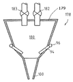
図8は、本発明による、新たなフォームを製造するための装置76と、生産機のヘッドボックス78とを示す。該図から分かるように、この具体例のヘッドボックス78は、主として、上方開放式のベイスン(basin; 水盤形容器)、又は少なくとも大気圧のベイスン80;フォーム用ノズル94;底部分98;及び開口部100;から成る。フォーム懸濁液は、ベイスン80中で造る。実際の生成物を造るのに必要な固形物の大部分は、1つ以上のパルパーの中に材料を導入するための従来技術の解決法で使用したのと同じ原理に従って、ベイスン80の中に導入する。換言すれば、ある製造のために、固形物用ベイスンの中に導入する量を測定し、繊維又は繊維マットは、カッターを用いて所望の長さに切断しておく。カッターの中に導入する繊維材料の量を厳密に調節することができる場合、繊維は、該カッター(図示せず)から直接ベイスンの中に導入することができる。繊維はまた、均一量のチョップトファイバー(chopped fibre;細断された繊維)を連続的にベイスン80の中に落下させるために、目盛付き運搬装置(calibrated conveyor)82を用いてベイスンの中に導入することもできる。図8はまた、ベイスン80の中に、例えば、充填材、結合剤、着色剤等、又はこれらの予備生成済み混合物(pre-produced mixture)を導入するのに、もう一台の目盛付き運搬装置83を使用する方法をも示している。本発明の要点は、前記の固形物の少なくとも一部分が、懸濁液の状態ではなく、実質的に乾燥した状態で該ベイスンの中に導かれることである。それら固形物は、必要に応じて、湿らすことができる;但し、如何なる場合でも、遊離水(free water)がそれら固形物と共に該ベイスンの中に全く導入されないようにして湿らすことができる。
FIG. 8 shows an
本発明の好ましい具体例の特徴は、生成物の構造(construction)を得るために必要な繊維成分の主要部分が、該ベイスンの中に「乾燥した状態で」導入されることである。この文脈における生成物の構造(construction of the product)とは、該生成物に特有な繊維網状構造を言い;多分、該生成物に属し且つ該生成物の使用中の特性に影響を及ぼす成分(例えば、活性炭、又は幾らかの液体吸収物質)を言う訳ではない。
これに加えて、特殊なフォームパルパー84中で生成したフォームは、ベイスン80の中に導入する。既に図1で示したように、フォームは、水、界面活性剤、及びガス(適当であるのは空気)からフォームパルパー84中で形成されるが、本方法には、他の如何なる材料も該パルパーの中に導入する必要がないという相違がある。しかし、ベイスン80の中に導入する前、フォームに固形物を混合することが望ましい場合、パルパー84中でフォームを形成する工程と絡めてそれを行うことができる。最適なフォームを形成するために、水及び界面活性剤の量は、パルパー84中に導入する時、互いに関連して割り当てる。所望のガス含有量と気泡寸法とを作り出すのに適した量の空気が、水と界面活性剤の混合物の中に取り込まれるように、該混合物は混合機を用いてかき混ぜる。
A feature of the preferred embodiment of the present invention is that the major part of the fiber components necessary to obtain the product construction is introduced “dry” into the basin. The construction of the product in this context refers to the fiber network that is unique to the product; presumably a component belonging to the product and affecting the properties of the product in use ( It does not mean, for example, activated carbon or some liquid absorbent material.
In addition, the foam generated in the
該図の点線で示すように、フォームの少なくとも一部分を、生産工程から管路86を経由して戻されるフォームと置換することは、可能であり且つ実用的である。パルパー84で造られてポンプ90を用いて管路92の中に送り込まれるフォームと、生産工程から管路86を経由して戻されるフォームの両者は、フォームのジェット(jets; 噴流)により生じる乱流によって、固形物が効果的に混合されるように、ノズル94を用いてベイスン80の中に時間単位当りの所望の量で噴霧するのが好ましい。フォーム懸濁液が形成される時、該懸濁液は、ベイスンの底部分98を経由して開口部100の方に、層流として導かれる。
フォームは、好ましくは各々の繊維の種類に適した速度(換言すれば、均質なフォーム懸濁液を形成するものの、それら繊維に大き過ぎる乱流を生じさせるほど大きくない速度)で、ノズル94から供給する。ある環境下では、ベイスンの中に機械混合機(図示せず)を配置するか;又は、超音波若しくはマイクロ波による混合を用いる;ことによって、混合工程を改善することができる。
As indicated by the dotted lines in the figure, it is possible and practical to replace at least a portion of the foam with a foam that is returned from the production process via
The foam is preferably from
本発明のこの具体例は、固形物が(好ましくは、生産機のワイヤの幅に対応する、ベイスン80の全長に渡って)定常流で導入しなければならないという点で、従来技術のフォーム懸濁液と相違する。このように、フォームもまた、約10cm間隔で配置されているノズル94からベイスンの中に導入する。フォームは、ベイスンの両側に配列されているヘッダー管(header tubes)96までポンプで送り込むのが好ましい(とは言え、場合によっては、ヘッダー管及びノズルは、ベイスンの一方側においてのみ必要である)。実際のノズル94は、ヘッダー管96からベイスンに通じており、他方、該ノズルは、当然、一層長いノズル管(nozzle tubes)と、該管の端部に配置されている実際のノズルとから成ることがある。もう1つの具体例によると、それらヘッダー管は、ベイスン80の上縁部(upper edge)と実質的に同じ高さに設置されており、そうすることによって、ノズルを備えたノズル管は、ベイスンの壁に穴を開けることなく、ベイスンの上部からベイスン80の中に導くことができる。それらノズル94は、必要に応じて、互いに向かい合わせてベイスン80の向かい側に配置するか;又はジグザグ(互い違い)に配置する;ことが可能であり、これは所望の乱流によって決まる。ノズル94は更に、ベイスン80のいずれか一方側か又は両側に幾つかの層を成して配置することができ、そうすることによって、繊維とフォームの多段階混合を計画することが可能となる。また、ベイスン80の1つの壁の全てのノズル94は一定方向である場合もあり、又はそれらの方向は所望通りに変えることができる。図8に示すように、本発明の好ましい具体例のベイスン80は、ベイスンの底部分98が実際上漏斗を形成するように、下向方向に狭くなっている。フォーム懸濁液は、底部分98から生産機のワイヤまで又はワイヤの間に、実質的に層流として供給する。しかし、ベイスンは場合によっては、それの底部分98に配置されている開口部100まで均一な幅であることもある。
This embodiment of the present invention is a prior art foam suspension in that solids must be introduced in a steady flow (preferably over the entire length of the
ウェブ形成プロセスのためには、ベイスン80中のフォーム懸濁液の液面レベル(surface level)を一定に維持することが極めて重要である。該液面レベルは、全ての成分(即ち、供給すべき固形物、及び管路92を経由して導入されるフォーム)が、厳密に測定された量でベイスンの中に導入されるという理由によって、既に一定に維持されている。これに加えて、レベル制御装置は当然、固形物及びフォームを導入することと、必要に応じて、新たなフォームを生成することの両方を制御するために、ベイスンと関連させて配置することができる。
For the web forming process, it is very important to keep the surface level of the foam suspension in the
三層ウェブを形成するのに適した、ヘッドボックスによる解決法を、図9と関連する好ましい具体例として示す。実際、該具体例におけるヘッドボックスは、図8に準じる3つの並列部分(78'、78''及び78''')に分割されているだけである。三層の完成品を検討する場合、並行部分(78'、78''及び78''')は、各々の直ぐ近くに配置することもできる。この場合、ヘッドボックスの並列部分(78'、78''及び78''')のベイスン(80'、80''及び80''')の底部分の開口部(101、102及び103)は並列であり、各々は、それら自体のフォーム懸濁液を、ワイヤ30の間のウェブ形成区域に供給する。開口部(101、102及び103)の1つ以上は、他の開口部と同時に(但し、僅かに早いか又は遅く)、ワイヤ30の間に開かないように計画することができる。この操作によって、ウェブの異なる層を相互に混合すべき量を制御することができる。例えば、中間の開口部102がウェブ形成部分の中に開くのが遅ければ遅いほど、表面層の形成はそれだけ先まで進んでおり、且つ、該中間層の繊維は、該表面層の繊維とそれだけ少ない量で混合させることができる。
A headbox solution suitable for forming a three-layer web is shown as a preferred embodiment in connection with FIG. In fact, the headbox in this example is only divided into three parallel parts (78 ′, 78 ″ and 78 ′ ″) according to FIG. When considering a three-layer finished product, the parallel portions (78 ', 78 "and 78'") can also be placed in close proximity to each other. In this case, the openings (101, 102 and 103) at the bottom of the basins (80 ′, 80 ″ and 80 ″ ′) of the parallel portions (78 ′, 78 ″ and 78 ′ ″) of the headbox are In parallel, each feeds its own foam suspension to the web forming area between the
図9による装置を用いて、釣り合いのとれた3種の異なる材料から三層ウェブを形成することが可能である。異なる固形物は、例えば、図8に関連させて記述した装置を用いて、ベイスン(80'、80''及び80''')の各々の中に供給することができる。しかし、ヘッダー管96から全てのベイスンに同一の新たなフォームを供給することが好ましく、そうすることによって、唯1台のフォームパルパーを使用することが可能となる。この文脈において、場合によっては、フォームの生成と絡めて、フォームパルパー内で、ウェブの全ての層に共通している固形物をフォームと混合することが好ましいと言うことができる。これの例は、例えば、全ての層に共通している結合剤又は繊維成分である。
Using the apparatus according to FIG. 9, it is possible to form a three-layer web from three different balanced materials. Different solids can be fed into each of the basins (80 ′, 80 ″ and 80 ′ ″) using, for example, the apparatus described in connection with FIG. However, it is preferred to supply the same new foam from the
しかし、場合によっては、ウェブの異なる層を得るために使用する材料は、互いに非常に異なっているので、全ての層に、よく似たフォームを使用することは好ましくない。この場合、異なるフォームは当然、異なるパルパーで生成されて、それら自体の管装置を経由して、ヘッドボックスのベイスンまで送り込む。この種の設備(arrangement; 配列)によって、例えば、ウェブの幾つかの層に、新たなフォームと一緒にある種の結合材を供給することが可能となる。
しかし、上記のことから、その設備は、単層、二層、三層、又は多層の生成物を製造するのに適用することができることに注目すべきである。このように、上記のことは、本発明の多くの変形の単なる一例に過ぎないものと見なすべきである。
図8及び図9に示す具体例のベイスンは、実質的に垂直に配置されている。2つの向き合ったワイヤ30と、それらワイヤの外側に配置されているサクションボックス32とから成っているウェブ形成区域も、実質的に垂直である。
However, in some cases, the materials used to obtain the different layers of the web are very different from each other, so it is not preferable to use a similar foam for all layers. In this case, different foams are naturally produced with different pulpers and fed through their own tubing to the basin of the headbox. This kind of arrangement makes it possible, for example, to supply some layers of the web together with a new form of some kind of binder.
However, it should be noted from the above that the equipment can be applied to produce single-layer, double-layer, triple-layer, or multilayer products. Thus, the above should be regarded as merely one example of the many variations of the present invention.
The example basins shown in FIGS. 8 and 9 are arranged substantially vertically. The web-forming area consisting of two
図10は更に、たとえ、実際のヘッドボックス;又は、フォーム懸濁液を混合するのに使用するそれらの上部ベイスン部分(80'、80''及び80''');が垂直であるとしても、ヘッドボックスの底部分(98'、98''及び98''')が所望により傾斜しているために、ワイヤ30とサクションボックス32とを水平に配置する方法を示している。
FIG. 10 further illustrates that even if the actual headboxes; or their upper basin portions (80 ′, 80 ″ and 80 ′ ″) used to mix the foam suspension, are vertical. FIG. 2 shows how the
上記の図8〜図10に示す、本発明による、ヘッドボックスを用いた解決法によって、これら具体例における、ヘッドボックスを上に向かって完全に開放する方法が明瞭に説明される。それによって、種々の材料を、形成すべきウェブに供給することが簡単に可能となる。一例を挙げれば、例えば、ガラス繊維、金属糸(metal thread)、リボン等を生成物の層の1つ以上の中に供給することが十分に可能である。他の使用可能な材料であって、上記のヘッドボックスを用いて、本発明による生成物の中に供給することのできる該材料は、例えば、種々の織物材料(textile)、炭素繊維、アラミド繊維及びポリエステル繊維のリボン等;導電性の糸(threads)、リボン又はケーブル;光ファイバー等;種々の抵抗ワイヤ又は網;他の網;温度の関数として色を変える物質;等である。 With the solution using the headbox according to the present invention shown in FIGS. 8 to 10 above, the method of completely opening the headbox upward in these embodiments is clearly described. This makes it possible to easily supply various materials to the web to be formed. In one example, it is well possible to feed, for example, glass fibers, metal threads, ribbons, etc. into one or more of the product layers. Other usable materials, which can be fed into the product according to the invention using the above-mentioned headbox are, for example, various textile materials, carbon fibers, aramid fibers And polyester fiber ribbons; conductive threads, ribbons or cables; optical fibers, etc .; various resistance wires or nets; other nets; materials that change color as a function of temperature;
これは、図11に例示する。図11は、図8に示す構造に類似する基本構造を有する装置を利用する、本発明の好ましい具体例に従って、生成物を製造する方法を示す。図11は、連続糸(continuous fibre)、連続ヤーン、連続リボン等を、ベイスン80を経由してウェブまで導く方法を示している。この図の具体例において、連続ヤーン106等は、ロール巻き(roll)等(図示せず)から;又は、場合によっては、生成物からまさに直接;2つの制御ローラー110の間の折り曲げローラー(folding roll)108から;糸巻きに巻く。制御ローラー110によって、連続ヤーン106の供給速度を調整して、生産機中のウェブ速度に対応させる。従って、連続ヤーン等がウェブに平行な直線のままであることは、この具体例の特徴である。連続ヤーンの真直度(straightness)は、ヘッドボックスの基本形態においてさえ、フォーム懸濁液を形成するのに必要な乱流が非常に弱いので、所望の方向から連続ヤーンの向きを大幅にそらすことはできないという事実によって、助けられている。ウォータ法により、このようにしてヤーンを供給することは可能ではない。なぜなら、ウォータ法では、ヘッドボックス内の乱流によって、連続ヤーンの波立ち(wave)が非常に強くなるので、最終生成物中の連続ヤーンの最終位置がランダムになるからである。
連続ヤーンが、最終生成物中の適切な位置に正確に達するのを確実にする方法は、適切な管を用いて、ヘッドボックスの乱流部を通って層流の領域まで、連続ヤーン等を導くことである。
This is illustrated in FIG. FIG. 11 illustrates a method for producing a product in accordance with a preferred embodiment of the present invention utilizing an apparatus having a basic structure similar to that shown in FIG. FIG. 11 shows a method of guiding continuous fiber, continuous yarn, continuous ribbon, etc. to the web via the
A method to ensure that the continuous yarn reaches exactly the right position in the final product is to use a suitable tube to move the continuous yarn etc. through the turbulence of the headbox to the laminar flow region. It is to guide.
図11に示す解決法は、連続ヤーン106の他に、ウェブの幅方向(width direction)又は生産機の幅方向が著しく広い寸法の生成物を導入するのに使用することができる。これらの一例は、生成すべき生成物の実質的に幅全体まで伸びる網(net)であって、ほとんどあらゆる所望の材料で造られている該網である。これの一例は、最終生成物を加温用電気装置に接続するための抵抗金網(resistor wire net)である。多くの可能性から選び得るもう1つのものは、ある理由により、本方法によって製造されている生成物と同時に造ることのできない予備成形済み補強用マットである。該マットは、ロール巻きから制御ローラーを経由してベイスンまで、更にそこからウェブの中に導く。第3の選び得るもう1つのものは、例えば、穿孔済み薄鋼板又は狭い鋼帯を、ベイスンを経由してウェブまで導くことである。該鋼板の穴を通して繊維と樹脂とを結合することによって、該鋼板をウェブに結合させることが確実となる。
The solution shown in FIG. 11 can be used to introduce products having dimensions that are significantly wider in the width direction of the web or in the width direction of the production machine in addition to the
ウェブが移動するのと同じ速度で、先ず、連続ヤーン、連続リボン、連続網等をウェブまで供給するための制御ローラー110を利用する解決法は、本明細書において、追加の具体例と言うことができる。製造が開始する時、それら制御ローラーは、連続ヤーン等の速度を僅かに落とすものと考えることができる。このことは、連続ヤーン等の気密度(tightness)を確保することであり、そのために、連続ヤーン等は生成物中の所望の位置に置かれて、いずれの方向にも動くことはできない。連続ヤーン等がそれの送り方向に対して垂直に動くのを停止させるもう1つの方法は、連続ヤーン等をウェブ中の適切な位置に導くための開口部100との関連でガイド(guides)を配置することである。また、ガイドを用いて、ベイスンの底部分までの層流領域へのみ;又は、所望により、ワイヤの間のウェブ形成区域の中の非常に深い所へ;連続ヤーン、連続リボン、連続網等を導くことも当然可能である。
A solution that utilizes the
図12は、本発明による、好ましいヘッドボックスによる解決法を示す。この解決法において、連続繊維、連続ヤーン等112は、中間ベイスン80''を経由して形成しているウェブの中に導く。該図は、制御ローラー110が、ウェブの速度を越える速度で連続ヤーン等112を導く方法を示している。その概念は、連続ヤーン等112とは別個の層(好ましくは、例えば、ガラス繊維であって、その層の上に連続繊維、連続ヤーン等が均一に覆われている該ガラス繊維)を形成することである。「たるんだ(loose; 緩んだ)」ヤーン等の要素をウェブの中に導入することは、ウォータ法では成功できる筈はない。なぜなら、ウォータ法では乱流が大きいため、繊維懸濁液中の繊維は、該ヤーンの上に捕らえることができず、そのため、生成物上に繊維を均一に分配することが不可能のようであるからである。また、この具体例の場合も、他の固形物(例えば、充填材、結合剤及び(又は)ある種の非連続繊維成分)をベイスン80''の中に供給するために、供給装置(feed apparatuses)(82及び83)をも使用する。
FIG. 12 shows a preferred headbox solution according to the present invention. In this solution, continuous fibers,
図11及び図12の場合、生成物の幅に沿って1つ以上の糸(threads)等が存在し得ることは明らかである。上記で既に述べたように、ヤーン等は積層物中の全層を形成するのに十分な量で供給することができる。更に、フォーム又はフォーム懸濁液を用いることなく、それら層の2つ以上の間のそれ自体の上に繊維、ヤーン等を供給することが可能である。また、例えば、図12に示すような解決法を用いて、ベイスン80'及び(又は)80'''を経由して、図11に示すように、形成されたウェブの中に連続繊維、連続ヤーン、連続網、連続ウェブ等を供給することも可能である。従って、連続ヤーン等を、ウェブの速度を越える速度でウェブのいずれの層の中にも導くことができることは明らかである。このように、図12に示すベイスン80''の送り込みによる解決法も、所望により、他のベイスン80'及び(又は)80'''と関連で配置することができる。
In the case of FIGS. 11 and 12, it is clear that there may be one or more threads or the like along the width of the product. As already mentioned above, the yarn or the like can be supplied in an amount sufficient to form all layers in the laminate. Furthermore, it is possible to feed fibers, yarns, etc. on itself between two or more of the layers without using a foam or foam suspension. Also, for example, using a solution such as that shown in FIG. 12, via the
図13は、本発明によるウェブ形成方法及びヘッドボックスのもう1つの好ましい具体例を示す。図13は、図7に絡めて既に解説したバンパ体の製法であって、新規なフォーム法を使用しているため、該バンパ体のために必要とされる全ての層が同一のウェブの中に送り込まれる該製法を示す。それによって、該バンパ体は、樹脂を単に添加することによって、単一積層マットから1つの製造段階で簡単に製造することができる。
図13は、2本の供給管(114及び116)が、ヘッドボックスの中間ベイスン80''を通って、該ヘッドボックスの開口部100を僅かに通り過ぎて、ウェブ形成区域のギャップ(gap; 隙間)に導かれる方法を示す。図7に示す生成物表面層64のために必要な材料は、ベイスン80'から供給し、表面層70のための材料は、室80'''から供給する。これに加えて、それら表面層の間のいわゆる流動層(flow layer)は、中間室80''から供給することが可能である。その層の樹脂は、生成物の全体に渡って均一に広がる。他方、管114は、もう1つのフォーム懸濁液を供給するのに使用され、図7の参照番号66によって示される、いっそう薄いマットウェブ(66及び68)で形成されるウェブであって、表面層(64及び70)の間に配置されている該ウェブを形成するのに必要である(それら管114の多くは、生成物の幅を横切って(across the width; 幅の端から端まで)(即ち、ヘッドボックスの長さ方向に)配置するのが好ましい)。従って、管116は、完成品中のマットウェブ68を形成するフォーム懸濁液を供給するのに使用される。図13は、管(114及び116)が、フォーム形態の繊維懸濁液を供給するのに使用されている状況を示している。同一の最終結果は、図11に示すウェブの上述の位置に、狭い繊維ウェブ又はリボンを供給することによって達成することができる。並行している多数の製品ブランク(product blanks)を有するウェブは、図13に例示される供給管(114及び116)を、ヘッドボックスの全長に沿って適切な間隔を置いて配列することによって製造することができる。次いで、それらブランクは後で切断して、例えば、生成物のローリング(rolling)との関連で、それら自身の別々のいっそう狭いウェブにすることができる。
FIG. 13 illustrates another preferred embodiment of a web forming method and headbox according to the present invention. FIG. 13 shows the bumper body manufacturing method already described with reference to FIG. 7 and uses a new foam method. Therefore, all layers required for the bumper body are contained in the same web. The manufacturing method to be sent to is shown. Thereby, the bumper body can be easily produced in one production stage from a single laminated mat by simply adding a resin.
FIG. 13 shows that two feed pipes (114 and 116) pass through the headbox
同一のフォーム懸濁液が管(114及び116)を通って供給されるということが、たとえ上記に開示されているとしても、それら管の各々の中に相違するフォーム懸濁液を導入することは、当然可能である。類似方法によって、フォーム懸濁液を用いて、いっそう狭い層の一方を形成し、また、完成ウェブを用いて他方を形成することができる。本発明のヘッドボックスによると、生成物の必要条件及び可能性(possibilities; 実現性)に従って、製造方法を自由に選定することが可能である。
2つの表面層の間の端部領域に補強用層を有する、図7による生成物が望まれる場合、図13による装置を用いるだけでなく;導入されるフォーム懸濁液の噴霧液の厚さが変化するように、単一の供給管の端部を形成することによって;該生成物を製造することができる。この場合、噴霧液のいっそう厚い部分は、重ね合わされる(superimposed)2枚の繊維ウェブ又はリボンに相当し、また、いっそう薄い部分は、これら繊維ウェブ又はリボンのいっそう広いものに相当する。
Introducing a different foam suspension into each of the tubes, even if disclosed above, that the same foam suspension is fed through the tubes (114 and 116). Is of course possible. In a similar manner, foam suspension can be used to form one of the narrower layers and the finished web can be used to form the other. According to the headbox of the present invention, it is possible to freely select the production method according to the requirements and possibilities of the product.
If a product according to FIG. 7 having a reinforcing layer in the end region between the two surface layers is desired, not only the device according to FIG. 13 is used; the thickness of the spray liquid of the foam suspension introduced The product can be produced by forming the end of a single feed tube such that In this case, the thicker part of the spray liquid corresponds to two fibrous webs or ribbons that are superimposed, and the thinner part corresponds to the wider of these fiber webs or ribbons.
図13は更に、フォーム懸濁液を、管(114,116)を経由してヘッドボックスに導く方法を示す。換言すれば、フォーム懸濁液は、所望により、目的に適した小型パルパーで別々に形成する。もう1つの可能性は、ベイスン中で生成され、該ベイスンから、層の間に形成すべきウェブの中に供給されるこのフォーム懸濁液のための、小型ベイスンを配置することである。
更に、ヘッドボックスの1つ以上の室を通って導かれる管は、完成ウェブ又はフォーム懸濁液の他に、生成物に必要な固形物をも、ウェブの中に供給するために使用することができる。それら固形物は、例えば、簡単に細かく切り刻んだ繊維(simply chopped fibres);結合材;結合材とチョップトファイバーの混合物;又は、実際の層形成に関係のない他のある種の材料;である場合がある。この場合、その材料は、例えば、液体を吸収するために使用されるSAP(高吸水性樹脂);又は、例えば、種(seeds)が一定間隔でリボンに固定される該リボン;である場合がある。
FIG. 13 further shows how the foam suspension is directed to the headbox via tubes (114, 116). In other words, the foam suspension is formed separately with a small pulper suitable for the purpose, if desired. Another possibility is to place a small basin for this foam suspension produced in the basin and fed into the web to be formed between the layers.
In addition, tubes that are routed through one or more chambers of the headbox should be used to supply the solids required for the product in addition to the finished web or foam suspension into the web. Can do. These solids are, for example, simply chopped fibers; binders; mixtures of binders and chopped fibers; or some other material not related to actual layering; There is a case. In this case, the material may be, for example, SAP (Super Absorbent Resin) used to absorb liquids; or, for example, the ribbon in which seeds are fixed to the ribbon at regular intervals. is there.
それら管(114及び(又は)116)を、ウェブの幅方向に伸びるフラットノズル溝(flat nozzle channels)と置き換えることができることは、更に明白である。それらフラットノズル溝によって、ウェブ中に幅の広いストリップを形成することができる。また、従来技術で開示したように、それら管又はジェット式溝(jet channels)は、長さ方向に移動することができ、それによって、ウェブ形成区域で材料を導入する地点を調整して、用途に適合させることができる。何らかの理由で、ウェブの長さ方向(longitudinal direction)に波状ストリップを形成することが望ましい場合、それら管及び(又は)ノズル溝はまた、当然、ウェブの垂直方向及び(又は)厚さ方向にも移動させることができる。 It is further evident that the tubes (114 and / or 116) can be replaced with flat nozzle channels extending in the width direction of the web. With these flat nozzle grooves, wide strips can be formed in the web. Also, as disclosed in the prior art, these tubes or jet channels can move in the length direction, thereby adjusting the point of introduction of material in the web forming area and Can be adapted. If for some reason it is desirable to form a wavy strip in the longitudinal direction of the web, these tubes and / or nozzle grooves will of course also be in the vertical and / or thickness direction of the web. Can be moved.
図14は、更に、本発明の好ましい具体例による、もう1つのヘッドボックス178による解決法を示す。上述のヘッドボックスとの主な相違点は、この具体例のヘッドボックスは閉じている(即ち、加圧されている)のに対して、他の具体例のヘッドボックスは大気圧であることである。実際面では、例えば、図8の具体例に対する図14の具体例の唯一の相違点は、チョップトファイバー及び他の固形物が、回転供給装置(rotary feeders)(182及び183)、又は他の相当する高圧供給装置を用いて、ヘッドボックス178の蓋179を通して導入されることである。全く同様に、もし用途が、ヘッドボックスを通って、形成すべきウェブまで、連続ヤーン、連続ケーブル、連続繊維等を供給することが必要ならば、該材料は、耐圧導管を経由して導入しなければならない。ヘッドボックスの蓋に対して密閉されている密封ロール(sealing rolls)は、連続ヤーン、連続リボン等を大気圧から加圧ヘッドボックスまで通過させる耐圧導管の例と見なすことができる。もう1つの解決法は、当然、加圧空間の中に、材料の完全なロール(roll)又はスプール(spool)を配置することである。
FIG. 14 further illustrates another
上述の典型的な具体例は、解説した新規なタイプのフォーム法によって、ほとんどあらゆる種類の繊維ベース生成物を製造することができることを開示する。このように、無機繊維と有機繊維の両者は、それら単独で又は互いと一緒に、繊維材料として使用することができる。無機繊維の例として、種々のガラス繊維、炭素繊維、石英繊維、セラミック繊維、ジルコニウム繊維、ボロン繊維、タングステン繊維、モリブデン繊維、ベリリウム繊維、及び種々の鋼繊維を挙げることができる。有機繊維の例には、ポリアミド繊維、ポリエステル繊維、ポリエチレン繊維、アセテート繊維、アクリル繊維、メラミン繊維、ナイロン繊維、モダクリル繊維、オレフィン繊維、ライオセル(lyocell)繊維、レイヨン繊維、アラミド繊維、及び種々の天然繊維(例えば、サイザル麻、ジュート繊維)が包含される。上述の繊維は、別個の単一繊維として、又は種々の繊維束として使用することができる。また、僅か2、3mmという非常に短い長さから十分連続した繊維まで、あらゆる繊維長さを使用することができる。 The exemplary embodiment described above discloses that almost any type of fiber-based product can be produced by the novel type of foam process described. Thus, both inorganic and organic fibers can be used as a fiber material, either alone or together with each other. Examples of inorganic fibers include various glass fibers, carbon fibers, quartz fibers, ceramic fibers, zirconium fibers, boron fibers, tungsten fibers, molybdenum fibers, beryllium fibers, and various steel fibers. Examples of organic fibers include polyamide fibers, polyester fibers, polyethylene fibers, acetate fibers, acrylic fibers, melamine fibers, nylon fibers, modacrylic fibers, olefin fibers, lyocell fibers, rayon fibers, aramid fibers, and various natural fibers. Fiber (eg, sisal, jute fiber) is included. The fibers described above can be used as separate single fibers or as various fiber bundles. Also, any fiber length can be used, from a very short length of only a few mm to a sufficiently continuous fiber.
上記から明らかなように、新規タイプの一連の生成物を開発した。これら生成物は、上述の新規な種類のフォームウェブ形成工程を用いてのみ製造することができる。上記の用語「フォーム(foam)」は、本明細書及び特許請求の範囲を通して、水及び界面活性剤から造られた新たなフォーム、又は生産機のサクションボックスから再循環された再使用可能なフォームを表現するものとして使用されてきて、該フォームによって、固形物の必須部分は、ワイヤ上の生成物に保持されてきたことに注目すべきである。このように、「フォーム」は、実質的に繊維を含有しないフォームを意味するものと規定することができよう。一方、用語「フォーム懸濁液(foam suspension)」は、繊維及び(又は)固形物を含有しているフォーム(即ち、原則として、それら固形物の必須部分をワイヤ上に与える生産機に近づいているフォーム)を意味する。 As is apparent from the above, a new type of product series has been developed. These products can only be produced using the new type of foam web forming process described above. The term “foam” is used throughout this specification and claims to refer to a new foam made from water and a surfactant, or a reusable foam recycled from the suction box of a production machine. It should be noted that the essential part of the solid has been retained in the product on the wire by the foam. Thus, “foam” could be defined to mean a foam that is substantially free of fibers. On the other hand, the term “foam suspension” refers to a foam that contains fibers and / or solids (ie, in principle, a production machine that provides the essential part of those solids on the wire. Form).
Claims (38)
Applications Claiming Priority (3)
| Application Number | Priority Date | Filing Date | Title |
|---|---|---|---|
| FI20012168 | 2001-11-09 | ||
| FI20012168A FI115512B (en) | 2001-11-09 | 2001-11-09 | Method and apparatus for performing foam molding |
| PCT/FI2002/000865 WO2003040469A1 (en) | 2001-11-09 | 2002-11-07 | Method and apparatus for foam forming |
Publications (2)
| Publication Number | Publication Date |
|---|---|
| JP2005508461A JP2005508461A (en) | 2005-03-31 |
| JP4276076B2 true JP4276076B2 (en) | 2009-06-10 |
Family
ID=8562215
Family Applications (1)
| Application Number | Title | Priority Date | Filing Date |
|---|---|---|---|
| JP2003542703A Expired - Lifetime JP4276076B2 (en) | 2001-11-09 | 2002-11-07 | Method and apparatus for forming foam |
Country Status (14)
| Country | Link |
|---|---|
| US (1) | US7416636B2 (en) |
| EP (1) | EP1461494B1 (en) |
| JP (1) | JP4276076B2 (en) |
| KR (1) | KR100866915B1 (en) |
| CN (1) | CN100529252C (en) |
| AT (1) | ATE361392T1 (en) |
| CA (1) | CA2466576C (en) |
| DE (1) | DE60219958T2 (en) |
| ES (1) | ES2286289T3 (en) |
| FI (1) | FI115512B (en) |
| NO (1) | NO20042381L (en) |
| PL (1) | PL210100B1 (en) |
| RU (1) | RU2304187C2 (en) |
| WO (1) | WO2003040469A1 (en) |
Families Citing this family (28)
| Publication number | Priority date | Publication date | Assignee | Title |
|---|---|---|---|---|
| FI115512B (en) * | 2001-11-09 | 2005-05-31 | Ahlstrom Glassfibre Oy | Method and apparatus for performing foam molding |
| US7641764B2 (en) * | 2004-12-03 | 2010-01-05 | Mitsubishi Paper Mills Limited | Non-woven fabric for gypsum board and process for producing the same |
| ES2610221T3 (en) * | 2012-07-20 | 2017-04-26 | Ahlstrom Corporation | A stitched unidirectional or multi-axial reinforcement and a method to produce the same |
| CN104487233B (en) * | 2012-07-20 | 2017-02-22 | 阿斯特罗姆公司 | A stitched unidirectional or multi-axial reinforcement and a method of producing the same |
| FI125024B (en) * | 2012-11-22 | 2015-04-30 | Teknologian Tutkimuskeskus Vtt | Moldable fibrous product and process for its preparation |
| FI127368B (en) * | 2013-06-20 | 2018-04-30 | Metsae Board Oyj | Process for the production of fiber web and fiber product |
| CN103437237B (en) * | 2013-08-07 | 2015-10-21 | 杭州诺邦无纺股份有限公司 | A kind of fiber web hygrometric state forming method and special purpose device thereof |
| FI126194B (en) * | 2013-09-13 | 2016-08-15 | Teknologian Tutkimuskeskus Vtt Oy | A method for forming a fibrous product |
| FI126699B (en) | 2014-05-15 | 2017-04-13 | Metsä Board Oyj | Process for making paperboard |
| SE539865C2 (en) * | 2014-10-03 | 2017-12-27 | Stora Enso Oyj | Method for producing a foam web involving electron beam radiation |
| AT517303B1 (en) * | 2015-06-11 | 2018-02-15 | Chemiefaser Lenzing Ag | Use of cellulosic fibers for producing a nonwoven fabric |
| MX2018004729A (en) | 2015-11-03 | 2018-07-06 | Kimberly Clark Co | Paper tissue with high bulk and low lint. |
| NZ743252A (en) | 2015-12-01 | 2019-09-27 | Essity Hygiene & Health Ab | Process for producing nonwoven with improved surface properties |
| FI127749B (en) * | 2016-05-23 | 2019-01-31 | Paptic Oy | Method for manufacturing a fibrous web |
| US10272399B2 (en) | 2016-08-05 | 2019-04-30 | United States Gypsum Company | Method for producing fiber reinforced cementitious slurry using a multi-stage continuous mixer |
| US11224990B2 (en) | 2016-08-05 | 2022-01-18 | United States Gypsum Company | Continuous methods of making fiber reinforced concrete panels |
| US10981294B2 (en) | 2016-08-05 | 2021-04-20 | United States Gypsum Company | Headbox and forming station for fiber-reinforced cementitious panel production |
| US11173629B2 (en) | 2016-08-05 | 2021-11-16 | United States Gypsum Company | Continuous mixer and method of mixing reinforcing fibers with cementitious materials |
| DK3507408T3 (en) | 2016-09-01 | 2021-04-06 | Essity Hygiene & Health Ab | PROCEDURE FOR MAKING THE NONWOVEN |
| RU2708341C2 (en) * | 2016-09-19 | 2019-12-05 | Федеральное Государственное Казенное Военное Образовательное Учреждение Высшего Образования "Военный Учебно-Научный Центр Сухопутных Войск "Общевойсковая Академия Вооруженных Сил Российской Федерации" | Gas-liquid plant for generation of water-air and hardening polymer foam with adaptive system for controlling physical parameters of foam camouflage coating |
| WO2018118683A1 (en) | 2016-12-22 | 2018-06-28 | Kimberly-Clark Worldwide, Inc. | Process and system for reorienting fibers in a foam forming process |
| AU2017441040B2 (en) * | 2017-11-29 | 2023-12-21 | Kimberly-Clark Worldwide, Inc. | Fibrous sheet with improved properties |
| FI20176206A1 (en) | 2017-12-31 | 2019-07-01 | Paptic Oy | Method of producing a fibrous product and a fibrous product |
| WO2020200403A1 (en) | 2019-03-29 | 2020-10-08 | Ahlstrom-Munksjö Oyj | A process of producing a heat storage material and a heat storage material |
| EP4085168A4 (en) | 2019-12-31 | 2024-01-17 | Kimberly Clark Co | Foam-based manufacturing system and process |
| CN115348850A (en) * | 2020-03-31 | 2022-11-15 | 金伯利-克拉克环球有限公司 | Zoned and/or layered substrates and methods and apparatus for making same |
| FI20205988A1 (en) | 2020-10-08 | 2022-04-09 | Munksjoe Ahlstrom Oyj | Filter sheet media and method for manufacturing a filter sheet media |
| DE102022115964A1 (en) | 2022-06-27 | 2023-12-28 | Andritz Küsters Gmbh | Method and device for producing a fiber web |
Family Cites Families (31)
| Publication number | Priority date | Publication date | Assignee | Title |
|---|---|---|---|---|
| US3007840A (en) * | 1958-04-03 | 1961-11-07 | Du Pont | Process of dispersing fibrous material in a foam and resulting product |
| DE1560872A1 (en) * | 1964-06-16 | 1970-06-11 | Kalle Ag | Process for the production of nonwovens |
| US3846232A (en) * | 1973-03-23 | 1974-11-05 | Valmet Oy | Twin-wire paper forming with wires wrapping around a suction web-forming breast roll and then following a curved path to a suction couch roll |
| GB1129757A (en) * | 1966-05-31 | 1968-10-09 | Wiggins Teape Res Dev | Method of producing a thixotropic liquid suspending medium particularly for the forming of non-woven fibrous webs |
| US3837999A (en) * | 1971-12-20 | 1974-09-24 | Kimberly Clark Co | Method of controlling the orientation of fibers in a foam formed sheet |
| FI65459C (en) * | 1972-04-07 | 1984-05-10 | Wiggins Teape Res Dev | FRAMEWORK FOR THE FRAMEWORK OF FIXED FIBERS |
| US3892622A (en) | 1973-12-05 | 1975-07-01 | Beloit Corp | Inlaying continuous filamentous reinforcement in a nonwoven web |
| US4062721A (en) * | 1976-10-26 | 1977-12-13 | Conwed Corporation | Use of surfactant to increase water removal from fibrous web |
| US4443299A (en) * | 1980-08-18 | 1984-04-17 | James River-Dixie/Northern, Inc. | Apparatus and method for the manufacture of a non-woven fibrous web |
| US4486268A (en) | 1981-05-04 | 1984-12-04 | Kimberly-Clark Corporation | Air/water hybrid former |
| US4543156A (en) * | 1982-05-19 | 1985-09-24 | James River-Norwalk, Inc. | Method for manufacture of a non-woven fibrous web |
| ATE48861T1 (en) | 1984-04-16 | 1990-01-15 | James River Norwalk Inc | DEVICE FOR PRODUCTION OF FIBER WEB. |
| US4686006A (en) * | 1984-04-16 | 1987-08-11 | James River - Norwalk, Inc. | Apparatus and method for the manufacture of fibrous webs |
| ATE140046T1 (en) * | 1990-10-17 | 1996-07-15 | James River Corp | FOAM-FORMING METHOD AND APPARATUS |
| US5164045A (en) * | 1991-03-04 | 1992-11-17 | James River Corporation Of Virginia | Soft, high bulk foam-formed stratified tissue and method for making same |
| US5200035A (en) * | 1992-01-24 | 1993-04-06 | James River Corporation Of Virginia | High uniformity foam forming |
| SE503065C2 (en) * | 1994-07-13 | 1996-03-18 | Moelnlycke Ab | Method and apparatus for producing a foam-shaped fiber or paper web |
| US5904809A (en) * | 1997-09-04 | 1999-05-18 | Ahlstrom Paper Group Oy | Introduction of fiber-free foam into, or near, a headbox during foam process web making |
| US6019871A (en) * | 1998-04-30 | 2000-02-01 | Ahlstrom Paper Group Oy | Effective utilization of sap in producing non-woven webs using the foam process |
| US6136153A (en) * | 1999-02-23 | 2000-10-24 | Ahlstrom Glassfibre Oy | Foam process web formation using pressure removal of fluid |
| US6238518B1 (en) * | 1999-03-02 | 2001-05-29 | Ahlstrom Paper Group Oy | Foam process for producing multi-layered webs |
| US6258203B1 (en) * | 1999-09-21 | 2001-07-10 | Ahlstrom Glassfibre Oy | Base webs for printed circuit board production using the foam process and acrylic fibers |
| BR0115032B1 (en) * | 2000-11-08 | 2012-01-10 | method of applying a liquid-based composition to a web of a fabric product. | |
| US20030031854A1 (en) * | 2001-08-07 | 2003-02-13 | Kajander Richard Emil | Method of making coated mat online and coated mat products |
| US6723670B2 (en) * | 2001-08-07 | 2004-04-20 | Johns Manville International, Inc. | Coated nonwoven fiber mat |
| FI115512B (en) | 2001-11-09 | 2005-05-31 | Ahlstrom Glassfibre Oy | Method and apparatus for performing foam molding |
| US6682215B2 (en) * | 2002-04-10 | 2004-01-27 | Fibermark, Inc. | Process and apparatus for making sheet of fibers using a foamed medium |
| US6835418B2 (en) * | 2002-05-31 | 2004-12-28 | Kimberly-Clark Worldwide, Inc. | Use of gaseous streams to aid in application of foam to tissue products |
| US6921459B2 (en) * | 2002-09-10 | 2005-07-26 | Fibermark, Inc. | Process for making a sheet of aramid fibers using a foamed medium |
| US7422660B2 (en) * | 2003-10-31 | 2008-09-09 | Sca Hygiene Products Ab | Method of producing a nonwoven material |
| SE0302875D0 (en) * | 2003-10-31 | 2003-10-31 | Sca Hygiene Prod Ab | Method of producing a nonwoven material |
-
2001
- 2001-11-09 FI FI20012168A patent/FI115512B/en not_active IP Right Cessation
-
2002
- 2002-11-07 AT AT02774805T patent/ATE361392T1/en not_active IP Right Cessation
- 2002-11-07 KR KR1020047006731A patent/KR100866915B1/en active IP Right Grant
- 2002-11-07 US US10/494,945 patent/US7416636B2/en active Active
- 2002-11-07 EP EP02774805A patent/EP1461494B1/en not_active Expired - Lifetime
- 2002-11-07 JP JP2003542703A patent/JP4276076B2/en not_active Expired - Lifetime
- 2002-11-07 DE DE60219958T patent/DE60219958T2/en not_active Expired - Lifetime
- 2002-11-07 WO PCT/FI2002/000865 patent/WO2003040469A1/en active IP Right Grant
- 2002-11-07 CA CA002466576A patent/CA2466576C/en not_active Expired - Lifetime
- 2002-11-07 ES ES02774805T patent/ES2286289T3/en not_active Expired - Lifetime
- 2002-11-07 PL PL368733A patent/PL210100B1/en unknown
- 2002-11-07 RU RU2004117524/12A patent/RU2304187C2/en active
- 2002-11-07 CN CNB02826875XA patent/CN100529252C/en not_active Expired - Lifetime
-
2004
- 2004-06-08 NO NO20042381A patent/NO20042381L/en unknown
Also Published As
| Publication number | Publication date |
|---|---|
| ATE361392T1 (en) | 2007-05-15 |
| NO20042381L (en) | 2004-06-08 |
| CN1612961A (en) | 2005-05-04 |
| DE60219958D1 (en) | 2007-06-14 |
| RU2304187C2 (en) | 2007-08-10 |
| PL368733A1 (en) | 2005-04-04 |
| RU2004117524A (en) | 2005-03-10 |
| CA2466576A1 (en) | 2003-05-15 |
| FI20012168A0 (en) | 2001-11-09 |
| KR100866915B1 (en) | 2008-11-04 |
| KR20050044346A (en) | 2005-05-12 |
| PL210100B1 (en) | 2011-12-30 |
| WO2003040469A1 (en) | 2003-05-15 |
| CA2466576C (en) | 2009-07-07 |
| US20050039870A1 (en) | 2005-02-24 |
| EP1461494A1 (en) | 2004-09-29 |
| ES2286289T3 (en) | 2007-12-01 |
| FI115512B (en) | 2005-05-31 |
| DE60219958T2 (en) | 2008-01-17 |
| CN100529252C (en) | 2009-08-19 |
| EP1461494B1 (en) | 2007-05-02 |
| JP2005508461A (en) | 2005-03-31 |
| FI20012168A (en) | 2003-05-10 |
| US7416636B2 (en) | 2008-08-26 |
Similar Documents
| Publication | Publication Date | Title |
|---|---|---|
| JP4276076B2 (en) | Method and apparatus for forming foam | |
| US8187418B2 (en) | Method of making multilayer nonwoven fibrous mats | |
| US6875308B2 (en) | Method of making foam coated mat online | |
| CA2396854C (en) | Method of making coated mat online and coated mat products | |
| US6238518B1 (en) | Foam process for producing multi-layered webs | |
| IE843322L (en) | Air-permeable sheet - like structure | |
| US5269049A (en) | Process and apparatus for dry forming of a material web from a long-fiber material | |
| US7597779B2 (en) | Shake mechanism for glass mat production line | |
| CN107378807A (en) | A kind of strong abrasive band paper | |
| US3384537A (en) | Multi-layer papermaking apparatus | |
| PL110071B1 (en) | Method of manufacturing multi-layer band of fibres | |
| EP1939351B1 (en) | Suction tube for nonwoven mat machine and method | |
| CN117144708A (en) | Automatic change layering paper apparatus for producing | |
| KR19980015181A (en) | Fiber-reinforced thermoplastic resin sheet and method and apparatus for manufacturing the same |
Legal Events
| Date | Code | Title | Description |
|---|---|---|---|
| A621 | Written request for application examination |
Free format text: JAPANESE INTERMEDIATE CODE: A621 Effective date: 20051017 |
|
| A977 | Report on retrieval |
Free format text: JAPANESE INTERMEDIATE CODE: A971007 Effective date: 20080731 |
|
| A131 | Notification of reasons for refusal |
Free format text: JAPANESE INTERMEDIATE CODE: A131 Effective date: 20080812 |
|
| A601 | Written request for extension of time |
Free format text: JAPANESE INTERMEDIATE CODE: A601 Effective date: 20081111 |
|
| RD04 | Notification of resignation of power of attorney |
Free format text: JAPANESE INTERMEDIATE CODE: A7424 Effective date: 20081017 |
|
| A602 | Written permission of extension of time |
Free format text: JAPANESE INTERMEDIATE CODE: A602 Effective date: 20081118 |
|
| A601 | Written request for extension of time |
Free format text: JAPANESE INTERMEDIATE CODE: A601 Effective date: 20081212 |
|
| A602 | Written permission of extension of time |
Free format text: JAPANESE INTERMEDIATE CODE: A602 Effective date: 20081219 |
|
| A521 | Request for written amendment filed |
Free format text: JAPANESE INTERMEDIATE CODE: A523 Effective date: 20090109 |
|
| TRDD | Decision of grant or rejection written | ||
| A01 | Written decision to grant a patent or to grant a registration (utility model) |
Free format text: JAPANESE INTERMEDIATE CODE: A01 Effective date: 20090206 |
|
| A01 | Written decision to grant a patent or to grant a registration (utility model) |
Free format text: JAPANESE INTERMEDIATE CODE: A01 |
|
| A61 | First payment of annual fees (during grant procedure) |
Free format text: JAPANESE INTERMEDIATE CODE: A61 Effective date: 20090305 |
|
| R150 | Certificate of patent or registration of utility model |
Ref document number: 4276076 Country of ref document: JP Free format text: JAPANESE INTERMEDIATE CODE: R150 Free format text: JAPANESE INTERMEDIATE CODE: R150 |
|
| FPAY | Renewal fee payment (event date is renewal date of database) |
Free format text: PAYMENT UNTIL: 20120313 Year of fee payment: 3 |
|
| FPAY | Renewal fee payment (event date is renewal date of database) |
Free format text: PAYMENT UNTIL: 20130313 Year of fee payment: 4 |
|
| R250 | Receipt of annual fees |
Free format text: JAPANESE INTERMEDIATE CODE: R250 |
|
| FPAY | Renewal fee payment (event date is renewal date of database) |
Free format text: PAYMENT UNTIL: 20130313 Year of fee payment: 4 |
|
| FPAY | Renewal fee payment (event date is renewal date of database) |
Free format text: PAYMENT UNTIL: 20140313 Year of fee payment: 5 |
|
| R250 | Receipt of annual fees |
Free format text: JAPANESE INTERMEDIATE CODE: R250 |
|
| R250 | Receipt of annual fees |
Free format text: JAPANESE INTERMEDIATE CODE: R250 |
|
| R250 | Receipt of annual fees |
Free format text: JAPANESE INTERMEDIATE CODE: R250 |
|
| R250 | Receipt of annual fees |
Free format text: JAPANESE INTERMEDIATE CODE: R250 |
|
| R250 | Receipt of annual fees |
Free format text: JAPANESE INTERMEDIATE CODE: R250 |
|
| R250 | Receipt of annual fees |
Free format text: JAPANESE INTERMEDIATE CODE: R250 |
|
| R250 | Receipt of annual fees |
Free format text: JAPANESE INTERMEDIATE CODE: R250 |
|
| R250 | Receipt of annual fees |
Free format text: JAPANESE INTERMEDIATE CODE: R250 |
|
| R250 | Receipt of annual fees |
Free format text: JAPANESE INTERMEDIATE CODE: R250 |
|
| R250 | Receipt of annual fees |
Free format text: JAPANESE INTERMEDIATE CODE: R250 |
|
| EXPY | Cancellation because of completion of term |