JP4274604B2 - Pouring cap - Google Patents
Pouring cap Download PDFInfo
- Publication number
- JP4274604B2 JP4274604B2 JP28827798A JP28827798A JP4274604B2 JP 4274604 B2 JP4274604 B2 JP 4274604B2 JP 28827798 A JP28827798 A JP 28827798A JP 28827798 A JP28827798 A JP 28827798A JP 4274604 B2 JP4274604 B2 JP 4274604B2
- Authority
- JP
- Japan
- Prior art keywords
- wall
- pouring
- inclined wall
- flexible
- upright
- Prior art date
- Legal status (The legal status is an assumption and is not a legal conclusion. Google has not performed a legal analysis and makes no representation as to the accuracy of the status listed.)
- Expired - Fee Related
Links
Images


Description
【0001】
【発明の属する技術分野】
本発明は、注出機能を備えた注出キャップに関するものであり、より詳細には、ガラス容器、剛性のプラスチック製容器、金属容器などのキャップとして用いられ、その一部を圧潰することにより、一定量の内容液を注出することが可能な注出キャップに関する。
【0002】
【従来の技術】
ガラス容器や剛性プラスチック製容器などに用いられる容器蓋としては、容器口部に装着され且つ注出用の孔を備えた中栓と、中栓を覆う様に設けられるオーバーキャップとから成り、容器を逆さまにして振ることにより中栓の注出用孔から内容液を注出するものが広く使用されている。この種の容器蓋は、例えば整髪料や香水等の化粧液を充填した容器に広く適用されているが、液垂れにより中栓が汚れるという欠点がある。また、容器を逆さまにして激しく振ることにより内容液を排出するため、排出される液量が一定でなく、さらに液をこぼし易いという欠点もある。
【0003】
上記の様な容器蓋の欠点を改善した容器蓋として、実開平6−81964号等には、中栓の天面に直立した内容液注出用のパイプ乃至ノズルを設け且つ該天面にドーム状に隆起部を設けることが提案されている。即ち、この容器蓋では、容器を逆さまにし、ドーム状隆起部を押圧して圧潰する(凹ます)ことにより、注出用のパイプ乃至ノズルから内容液が排出される。従って、排出される液量は、凹まされたドーム状隆起部の容積に相当し、ほぼ一定量の液を排出することができるという利点がある。また、凹まされたドーム状隆起部の弾性復帰により、注出用のパイプ乃至ノズルから外気が容器内に吸引され、これによって液垂れが有効に防止できるというものである。
【0004】
【発明が解決しようとする課題】
しかしながら、上記先行技術などに開示されている容器蓋は、容器口部が小径の容器、例えばバッグ等に入れて持ち運びする化粧品の様な小さな容器には適用が困難であるという問題がある。
即ち、このような容器に用いる容器蓋では、必然的に容器口部に装着される中栓の天面の大きさもかなり小さく、この小面積の天面内に注出用のパイプ乃至ノズルとドーム状隆起部の両方を形成しなければならない。従って、ドーム状隆起部も著しく小さなものとせざるを得ず、この結果として、ドーム状隆起部に十分な凹み容積を持たせることができなくなり、十分な液量を排出することが困難となり、一定量の液を取り出すためには、何回も繰り返し圧潰操作を行わなければならないからである。
また、ドーム状隆起部は、これを圧潰して凹ませた時に、元の形状に復帰しにくく、液垂れ防止機能が不十分になるとという問題もあり、このような傾向は、ドーム状隆起部が大きくなる程顕著である。即ち、ドーム隆起部を押圧して凹ませた時、ドーム状の壁部が完全に反転して安定な形状となり易く、このため、凹んだ形状がなかなか元に戻らなくなり、液垂れ防止機能が不満足なものとなる。従って、ドーム状隆起部は小さな形状とせざるを得ず、弾性復帰により液垂れ等を防止するためには、1回の圧潰により注出される液量はますます少量となってしまう。さらに、ドーム状隆起部が小さなものとなる程、液を排出するためのドーム状隆起部の圧潰操作が行い難くなってしまう。
【0005】
従って本発明の目的は、キャップの1回の圧潰により、十分な量で且つ一定量の液を安定して排出することができ、しかも、容器口部が小径の容器にも適用できる注出キャップを提供することにある。
本発明の他の目的は、容器内容液を排出するためのキャップの圧潰による弾性変形を容易に行うことができ、しかも、この弾性変形された部分の弾性復帰が瞬時に行われ、内容液の液垂れ等の問題も有効に防止された注出キャップを提供することにある。
【0006】
【課題を解決するための手段】
本発明によれば、
容器口部に保持固定され且つ上端に環状の水平フランジを備えた環状体と、該環状体上に設けられた注出筒とから成る注出キャップにおいて、
前記注出筒は、下端部が前記環状体の水平フランジに接続された筒状側壁を備えており、前記筒状側壁の上端部によって形成される上端面には、頂壁と、該頂壁から下方に傾斜したベース傾斜壁とが形成されており、該頂壁上に、筒状側壁内空間と通じ且つ直立した注出パイプが設けられ、該ベース傾斜壁上には、弾性の圧潰部が突出して設けられ、
該圧潰部は、少なくとも2個の半筒状の直立壁と、2個の可撓性傾斜壁とが交互に連なって複数段に形成され、該ベース傾斜壁上からは第1の直立壁が立ち上がり、該第1の直立壁の上端は第1の可撓性傾斜壁で閉じられ、該第1の可撓性傾斜壁上からは第2の直立壁が立ち上がり、該第2の直立壁の上端は第2の可撓性傾斜壁で閉じられ、該第1の可撓性傾斜壁及び該第2の可撓性傾斜壁は、それぞれ上端部分で該頂壁に連なっている、
ことを特徴とする注出キャップが提供される。
【0007】
上記の注出キャップにおいて、内容液の排出は、このキャップが装着されている容器を傾け、前記筒状側壁のベース傾斜壁に形成されている弾性圧潰部を押圧して圧潰することにより容易に行うことができる。即ち、この押圧により凹まされた弾性圧潰部の容積に対応して、一定量の液が注出パイプから排出される。従って、1回の圧潰により常に一定量の液を排出することができるし、また押圧力を加減して弾性圧潰部の凹みを調節することにより、液量を調節することができる。
さらに、押圧力を解除すれば、凹まされた圧潰部は、元の形状に弾性復帰し、注出パイプからの外気の流入により、液垂れ等が有効に防止される。
【0008】
本発明において、最も重要な特徴は、液を注出するための弾性圧潰部が、傾斜壁(ベース傾斜壁)上に形成されていることにあり、これにより、この注出キャップを口部の径が小さな容器にも適用することが可能となるのである。
即ち、この注出筒の水平壁に弾性圧潰部を形成すると、この水平壁は、当然のことながら容器口部の径よりも小さく、しかも、この水平壁には注出パイプも設けなければならない。従って、弾性圧潰部も小さなものとなってしまい、このような容器蓋は、口部径の小さな容器に適用することが困難となってしまうのである。
特に、これに対して、本発明にしたがって注出筒の筒状側壁にベース傾斜壁を形成し、このベース傾斜壁上に弾性圧潰部を形成した場合には、ベース傾斜壁の大きさが容器口部の径に依存せず、筒状側壁の長さやベース傾斜壁の傾斜角を調整することにより、このベース傾斜壁を大きくすることができる。即ち、この注出筒の上端に注出パイプが設けられている場合や口部径が小さな容器に適用する場合にも、ベース傾斜壁を大きく設定することにより、弾性圧潰部の容積を大きくすることができ、この結果、弾性圧潰部を押圧することにより注出される内容液の液量を多くし且つ押圧操作も容易に行うことができる。
このように本発明の注出キャップは、口部径の小さな容器に適用することができ、これは本発明の大きな利点である。
またベース傾斜壁上に形成される弾性圧潰部の特殊な形状により、圧潰された弾性圧潰部の元の形状への弾性復帰を瞬時に行うことが可能となり、液垂れ防止機能を著しく向上させることができることも本発明の大きな利点である。
【0009】
尚、本発明においては、筒状側壁の上端に上述したベース傾斜壁が形成されていることから、筒状側壁の上端に形成される頂壁は、通常、円の一部を切り欠いた三日月形状となり、この三日月形状の頂壁に内容液注出用の注出パイプが設けられることになる。
また、本発明の注出キャップは、通常、このキャップの注出筒を覆う様に、該注出キャップの環状体に係合固定されるオーバーキャップを組合せた複合容器蓋として使用に供される。このオーバーキャップは、天板と、天板の周縁から垂下しているスカート部とから形成されており、天板の内面には、該オーバーキャップを前記環状体に係合固定したときに、前記注出パイプの上端を閉じるための閉塞突起が形成されている。この閉塞突起と注出パイプ上端との係合により良好な密封性を保持することができる。例えば、注出パイプを直立させない場合には、この様な閉塞突起による密封が困難となる。
この様に、上述した注出キャップをオーバーキャップと組み合わせた複合容器蓋は、密封性が特に要求される容器、例えばバッグ等に入れて持ち運びされる化粧品などの容器に適用することができ、これも本発明の大きな利点である。
【0010】
【発明の実施の形態】
本発明においては、容器口部に保持固定される環状体と、容器内容液を注出するための注出パイプを備えた注出筒とを、一体に形成することもできるし、また両者を別体の部材として形成し、これらを組み合わせて使用することもできる。
環状体と注出筒とを一体に形成した場合には、この注出キャップを構成する部品数が少なくなるため、生産行程が簡略化されるというメリットがある。
一方、環状体と注出筒とを別体の部材として形成した場合には、構成部品数は多くなるが、環状体と注出筒とを別のプラスチックで形成することができるというメリットがある。即ち、環状体は、嵌合或いは螺子固定等の手段により容器口部の保持固定されるものであるため、比較的剛性を有し且つ強度の高いプラスチックで形成するのがよく、一方、注出筒は、弾性圧潰部を有するものであるため、可撓性の高い柔軟なプラスチックで形成するのがよい。このような特性に応じて、環状体と注出筒とを異なるプラスチックで形成することができるのが、この態様の利点である。
また、環状体と注出筒とを一体に形成する場合には、成形終了後の型抜きのために、注出筒の筒状側壁の内周面が環状体の水平フランジ内周面と合致しなければならず、従って、注出筒(筒状側壁)の内径が制限されるが、環状体と注出筒とを別体とした場合には、このような型抜きのための大きさの制限がない。即ち、注出筒(筒状側壁)の内径を大きくすることができ、従って、弾性圧潰部の容積も大きくすることができ、この結果、1回の圧潰により注出される内容液の液量を多くすることができるという利点もある。
【0011】
尚、環状体と注出筒とを別体とした場合には、環状体の水平フランジの上面に適当な突起を設け、この突起を利用して、注出筒の筒状側壁の下端を係合乃至嵌合させることにより、両者を結合させることができる。
また、筒状側壁の下端に水平フランジを設け、この水平フランジを環状体の水平フランジと容器口部上端との間で挟持せしめることにより、両者を結合させることもできる。この場合、筒状体は、可撓性の高い柔軟なプラスチックで形成されるため、筒状側壁下端の水平フランジがパッキンとして機能し、この結果、密封性を向上させることができる。
【0012】
本発明において、筒状側壁上端の頂壁に連なるベース傾斜壁上に形成される弾性圧潰部は、ベース傾斜壁から立ち上がって軸方向に延びており且つ上端が一定の角度で傾斜している半筒状の軸方向側壁と、該軸方向側壁上端を閉じる様に形成されている可撓性の傾斜壁とから形成するのが好ましい。この場合、軸方向側壁の周方向両端は、高さが実質上ゼロであり且つこの部分で前記頂壁に連なっており、可撓性の傾斜壁は、ベース傾斜壁と水平面とがなす傾斜角よりも小さい角度で前記頂壁に連なっている。
【0013】
弾性圧潰部の形状を上記の様にすると、この圧潰部の可撓性傾斜壁を押圧すると、この可撓性傾斜壁及び軸方向側壁は、何れも上端の頂壁との境界部を支点として下方に凹んでいくため、圧潰がスムーズに進行する。しかも、弾性圧潰部の凹み形状は、凸凹の不安定な形状となるため、押圧力を解除すると、瞬時に元の形状に弾性復帰する。従って、注出パイプに残存或いは付着した液は直ちに容器内に回収され、液垂れ等が有効に防止される。また、弾性圧潰部を押圧して内容液を排出する際、軸方向側壁を凹ます時に比較的大きな力を要するため、作業者に適度な触感を与えるという利点もある。
例えば、この圧潰部をドーム状に形成した場合、圧潰により凹まされた形状が安定なドーム反転形状となり易いため、押圧力を解除しても、元の形状に復帰しにくく、また圧潰する時に作業者に与える触感が鈍いという欠点があるが、弾性圧潰部を上述した形状とすることにより、このような問題は有効に解決される。
また、弾性圧潰部の形状を上記の様にすると、この圧潰部を圧潰する時及び元の形状に復帰する時に音が発生し、この結果、上記の触感と共に、圧潰作業を行ったという作業感が高められ、容器の商品価値が高められる。
【0014】
また本発明においては、弾性圧潰部の軸方向側壁の肉厚を、ベース傾斜壁の内周部(軸方向側壁の付け根部の近傍)及び軸方向側壁上端の可撓性傾斜壁の厚みよりも肉厚とすることが好ましい。これにより、軸方向側壁の自立性が強められるため、圧潰した時の弾性圧潰部の弾性復帰力が更に高められ、液垂れ防止機能を一層高めることができる。
【0015】
本発明においては更に、上述した半筒状の軸方向側壁と、軸方向側壁上端に連なる可撓性傾斜壁とを交互に連ねて弾性圧潰部を多段形状とすることも可能である。
ベース傾斜壁上に形成される中空の弾性圧潰部の容積を大きくする程、1回の圧潰により注出される液量を多くすることができ、軸方向側壁上端に連なる可撓性傾斜壁の水平面となす傾斜角度(軸方向側壁上端の傾斜角に相当)がゼロに近づく程(水平面に近くなる程)、弾性圧潰部の容積は大きくなる。しかしながら、この可撓性傾斜壁の傾斜角度がゼロに近づく程、弾性圧潰部をスムーズに凹ませることが困難となってしまう(圧潰性が低下する)。しかるに、上記のように、弾性圧潰部を多段に形成することにより、その圧潰性を損なうことなく、弾性圧潰部の内容積を可及的に大きくすることができる。
【0016】
また上述した種々の構造の弾性圧潰部においては、筒状側壁上端の頂壁に連なっている最上部の可撓性傾斜壁、特に該可撓性傾斜壁の上端部に、弾性圧潰部を圧潰するための押圧片を設けることが好ましい。このような押圧片をベース傾斜壁に押しつけることにより、この弾性圧潰部をスムーズに圧潰し、内容液の注出を容易に行うことができる。この場合、作業者は、押圧片がベース傾斜壁に当接したことにより、注出作業の終了を確認することができる。
【0017】
上述した弾性圧潰部の可撓性傾斜壁や半筒状の軸方向側壁が連なっている頂壁に設けられる注出パイプは、容器口部の中心、即ち注出筒の中心に配置されていてもよいが、特に好ましくは、その中心から偏心した位置に形成されていることが好ましい。このような偏心した位置に注出パイプを形成させることにより、頂壁を可及的に小さくし、前述したベース傾斜壁をできるだけ大きなものとすることができるため、弾性圧潰部の容積を大きくして圧潰による液の注出量を多くする上で有利となる。
【0018】
また、上述した構造の注出キャップをオーバーキャップと組み合わせて複合容器蓋として使用する場合、上記注出パイプが直立して設けられているため、オーバーキャップの天板内面には、オーバーキャップを環状体に係合固定して注出筒を覆った時に、注出パイプの上端を閉じる閉塞突起を設けることができる。この閉塞突起は、注出パイプの上端の内部に嵌め込まれるようなものでもよいし、これを環状とし、この内部に注出パイプの上端が嵌め込まれるようなものでもよい。
【0019】
上記の複合容器蓋においては、環状体とオーバーキャップとは、オーバーキャップが環状体に係合固定された状態で、両者が、外観上、一体の物品に見えるようにすることが商品価値を高める上で好ましい。このために、両者が係合固定された状態で上面から見たとき、上記環状体及びオーバーキャップはほぼ同一の外形を有しているのがよい。また、容器の胴部の水平断面形状が楕円形である時、上記の両者の外形も楕円形とするのがよい。
さらに、オーバーキャップの上面から見ての外形が楕円形である場合、前述した閉塞突起を2個形成し、これらの閉塞突起を、上記楕円形の長軸上で且つ短軸を中心として互いに線対称となる位置に配置しておくことが好ましい。このような位置に2個の閉塞突起を設けることにより、オーバーキャップの何れの方向で環状体に係合せしめた場合にも、確実に注出パイプの上端を閉じることが可能となり、オーバーキャップを装着する時に位置合わせの必要がなくなり、作業性が向上する。
また、オーバーキャップの上面から見ての形状を円形とした場合には、通常、注出パイプの位置は容器口部の中心に設定するのがよく、容器口部の中心から偏心した位置に注出パイプを配置した時には、注出パイプの上端を上記閉塞突起により確実に閉じるために、格別の位置決め機構を設けることが必要となる。
【0020】
上述した注出キャップ或いは複合容器蓋において、前記環状体は、嵌合或いは螺子係合により容器口部に装着されるが、使用済みの容器蓋を容器と分別して廃棄するという見地からは、螺子係合により容器口部に装着される構造とすることが好適である。
更にこの環状体は、内面に螺条を備えた内筒と、該内筒の外側に位置する外筒とを備えていることが好ましい。即ち、螺子係合により環状体を容器口部に固定する場合、螺条を有している容器口部の外周面の形状は円筒であるため、環状体の螺条を有する部分も円筒となる。しかるに、容器の胴部形状は円筒に限定されるものではなく、例えば平断面が楕円形のような偏平した形状の胴部を有する容器もある。例えば、胴部に貼られたラベルなどをよく見ることができるという利点を有しているため、小容積の容器などは、このような偏平した形状の胴部を有しているものが多く、特に化粧品などの分野によく見られる。従って、容器口部に螺子固定される環状体を、上記のように外筒と、螺条を備えた内筒とから構成することにより、内筒は円筒形状であるとしても、外筒の下端の外形を容器肩部(胴部から口部に連なる部分)の形状に滑らかに連続させることができる。即ち、容器の胴部がどのような形状であっても、環状体の外形を、この容器肩部の形状に連続させることができ、容器蓋が容器の一部分に見えるような形状とすることにより、容器の商品価値を高めることができ、特に容器の見栄えをが要求される化粧品などの分野では、このような内筒と外筒との二重壁構造の環状体を備えた注出キャップ或いは複合容器蓋は、極めて有用である。
【0021】
このような二重壁構造の環状体において、前記内筒の上端は、水平フランジの内面に連なっており、該水平フランジの外周縁に前記外筒の上端が連なった構造とする。この外筒の途中に水平段差部を形成し、且つ水平段差部よりも上方の外筒の外周面に、オーバーキャップを係止するための突条を形成するのがよい。
即ち、このような位置に形成されている環状体の突条に、オーバーキャップを係止して位置固定するような構造とし、オーバーキャップも容器肩部の外形と同じ形状とすることにより、この複合容器蓋と容器とが外観上、全体として一体物として観察され、商品価値が著しく高められるのである。
【0022】
【実施例】
本発明を、以下、添付図面に示す具体例に基づいて詳細に説明する。
(第1実施例)
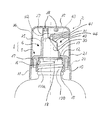
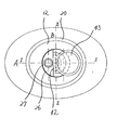
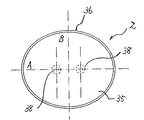
図1乃至乃至図5は、本発明の注出キャップの第1実施例を示すものであり、図1は、第1実施例の注出キャップの全体構造を、オーバーキャップ及び容器口部と共に示す側断面図であり、図2は、図1とは90度異なる方向からみた注出キャップの一部断面、一部側面を、オーバーキャップ及び容器口部と共に示す図であり、図3は、注出キャップの上面(オーバーキャップを取り外した状態)を容器と共に示す図であり、図4は、図1に示されている注出キャップ(環状体と注出筒との一体成形物)の側面を、オーバーキャップの側断面と共に示す図であり、図5は、図1の注出キャップに装着されるオーバーキャップの上面を示す図である。
尚、図1に示されている注出キャップの側断面は、図3のI−I断面に相当し、図2に示されている注出キャップの側断面(一部側面)は、図3のII−II断面に相当する。
【0023】
特に図1、図2及び図4を参照して、全体として1で示す注出キャップは、オーバーキャップ2と組み合わせて複合容器蓋として使用される。
この注出キャップ1は、容器口部100に螺子固定される環状体5と、容器内容液を注出するための注出筒6とから成っており、図1及び2から明らかな通り、環状体5と注出筒6とは一体に形成されている。
【0024】
また環状体5は、内筒10と外筒11とを備えており、両者は、上端の水平フランジ12を介して連なっている。水平フランジ12は、特に図3に示されている様に楕円形(長軸A,短軸B)であり、外筒11は、この水平フランジ12の外周縁から下方に延びており、内筒10は、外筒11よりも内側で水平フランジ12の内面から下方に延びている。
【0025】
内筒10の内面には,容器口部100の外周面に形成されている螺条100aと螺子係合する螺条15が設けられており,これら螺条同士の係合により、環状体5は、容器口部100に螺子固定される。従って、内筒10は、容器口部100と同様、円筒形状であり、その平断面は円形となっている。
また内筒10の内面には、上記螺条15の上方に、パッキン保持用の周状突起16が形成されており、さらに水平フランジ12の内面には、内筒10よりも内側となる位置にパッキン押圧用の下方突起17が形成されている。即ち、図1及び図2に示されている様に、上記内筒10の上方部分にパッキン18が落下しないように周状突起16により保持され、この状態で、内筒10を容器口部100にしっかりと螺子固定する。これにより、上記下方突起17がパッキン18を容器口部100の上端にしっかりと密着し、良好な密封性が確保される。
【0026】
また、図1から明らかな通り、外筒11の途中には水平段差部20が形成されており、水平段差部20よりも上方部分は小径で且つ下方部分は大径となっている。この外筒11の水平段差部20よりも上方部分の外周面に、オーバーキャップ2を係止するための係止突起21が形成されている。
さらに図3の上面図から明らかな通り、水平フランジ12の外形は楕円形となっており、従って水平フランジ12の外周縁から延びている外筒11の平断面形状も楕円形となっている。図1は、この楕円形の長軸A上の断面を示し、図2は短軸B上の断面を示すものであり、特に図2から理解されるように、短軸B上においては、内筒10の壁と外筒11の上方部分の壁とは重なっている。
【0027】
注出筒6は、筒状側壁25と、筒状側壁25の上端の一部を閉じる様に形成され且つ実質上水平方向に延びている頂壁26を備えており(図3及び図4参照)、頂壁26上には、注出パイプ27が設けられている。この注出筒6は、前述した環状体5と一体に形成されており、従って、筒状側壁25は、環状体5の水平フランジ12の内周縁から立ち上がったものとなっている。即ち、この筒状側壁25の内周面と水平フランジ12の内周縁との間に段差が存在すると、成形後の型抜きが困難となってしまうため、このような段差のない形状とすることが必要となる。
また、筒状側壁25の上端は一部が傾斜しており、特に図1,2及び4から明らかな通り、この傾斜した上端を閉じる様にしてベース傾斜壁30が形成され、このベース傾斜壁30は、頂壁26に連なっている。従って、図3に示されている様に、頂壁26は三日月形状を有し、且つ注出パイプ27は、容器口部100の中心(環状体5の中心)から偏心した位置に形成されることになる。
さらにベース傾斜壁30上には、弾性の圧潰部31が形成されており、この圧潰部31を指で押圧して凹ますことにより、注出パイプ27の先端から容器内容液の注出が行われる。この圧潰部31の構造については後述する。
【0028】
またオーバーキャップ2は、天板35と、天板35の周縁から下方に延びているスカート部36とから形成されており、スカート部36の内面には、前述した環状体5の外筒11の外周面に設けられている係止突起21と係合する突条37が形成されている。即ち、このオーバーキャップ2は、上記突条37と係止突起21との係合により、環状体5の外筒11に係止固定され、この状態において、スカート部36の下端は、外筒11に形成されている水平段差部20と密着するようになっている。従って、図5に示されているように、オーバーキャップ2の平断面形状は、環状体5の外筒11の平断面形状とほぼ一致する楕円形状となっており、これにより、容器口部100に装着されているこの複合容器蓋は、容器と一体に連なる外観を有し、商品価値の高いものとなっている。
【0029】
さらにオーバーキャップ2の天板35の内面には、閉塞突起38が2個形成されており、このオーバーキャップ2を環状体5に固定した時に、注出パイプ27の上端内部に、2個の閉塞突起38の何れか一方が嵌め込まれ、この嵌合により、閉塞突起38の外周面が注出パイプ27の上端の内周面に密着して注出パイプ27の上端が閉じられ、内容液の漏れが防止されるようになっている。
ところで、上述した楕円形状のオーバーキャップ2は、長軸A或いは短軸Bを中心として線対称の形状であるから、環状体5に係止固定されているオーバーキャップ2の向きは2通りある。一方、注出筒6に設けられている注出パイプ27は、環状体5の中心(容器口部100の中心に相当)から偏心する位置に形成されている。このため、環状体5に係止固定されているオーバーキャップ2の向きが何れの場合であっても、確実に閉塞突起38と注出パイプ27の上端とが嵌合するように、閉塞突起38を2個設けることが必要となる。この場合、図3に示されている様に、注出パイプ27の位置を、外筒11が形成する楕円(図5のオーバーキャップ2が形成する楕円と実質上同じ)の長軸A上に設定すると共に、2個の閉塞突起38を長軸A上で且つ短軸Bを中心として互いに線対称となる位置に設定するのがよい。
尚、閉塞突起38は、これを注出パイプ27の上端内部に嵌め込むようなものに限定されず、例えば、この閉塞突起38を環状にし、この内部に注出パイプ27の上端が嵌め込まれるようなものであってもよい。この場合には、注出パイプ27の上端の外周面に閉塞突起38の環状内周面が密着して注出パイプ27の上端が閉じられる。
【0030】
上述した本発明の注出キャップ1において、ベース傾斜壁30上に形成されている弾性の圧潰部31は、このキャップの軸方向を指向している半筒状の直立壁40と、この直立壁40の上端を閉じる様に形成されている可撓性の傾斜壁41とから形成されている。即ち、直立壁40の上端は傾斜しており、且つ可撓性傾斜壁41は、頂壁26にも連なっている。特に図1及び2から理解される様に、直立壁40の高さは、ベース傾斜壁30の上端の位置で丁度ゼロとなっている。即ち、ベース傾斜壁30、直立壁40及び可撓性傾斜壁41は何れも上端で水平方向に延びている頂壁26に連なっている形状となっており、ベース傾斜壁30の水平面に対する傾斜角αは、可撓性傾斜壁41の水平面に対する傾斜角βよりも大きくなっている(図3参照)。
【0031】
また可撓性傾斜壁41の上端には、筒状の支柱42を介して押圧片43が形成されており、この押圧片43の裏面の中央部分には、支柱42に連なるリブ44が形成されている。
即ち、容器を傾けた状態で、この押圧片43を指で押圧することによって弾性の圧潰部31が圧潰されて内容液の注出が行われる。この圧潰に際しては、先ず支柱42により可撓性傾斜壁41が凹まされ、次いでリブ44が直立壁40に当接することによって、ベース傾斜壁30の薄肉の内周部が下方に圧潰されて直立壁40がベース傾斜壁30側に傾倒し、次いで押圧片43の裏面がベース傾斜壁30の外周縁に密着した段階で圧潰部31が完全に凹まされ、この圧潰部31の容積に対応して一定量の内容液が注出パイプ27から注出される。
【0032】
かかる態様においては、圧潰部31がベース傾斜壁30に形成されているため、この圧潰部31の容積を大きくすることができ、特に容器口部100の径が小さい小容積の容器に、この注出キャップ1を有効に適用できる。即ち、容器口部100の径が小さい場合にも、注出筒6の高さや傾斜角αを調整することによって、ベース傾斜壁30を大きくすることが可能であり、従ってベース傾斜壁30を大きくすることにより、圧潰部31の容積を大きくし、1回の圧潰により注出される液量を多くすることができる。このベース傾斜壁30の傾斜角αは、目的とする圧潰部の容積が確保されるように、容器口部の径等に応じて設定すればよい。
【0033】
また、押圧片43を指で押圧して圧潰させていくと、直立壁40が凹み難いため、リブ44が直立壁40に当接した時点で、使用者に十分な触感を与える。また、押圧片43の裏面がベース傾斜壁30に密着したことにより、作業者は、圧潰部31が完全に凹んだ状態をはっきりと認識することができ、しかも、圧潰作業の終了点をはっきり認識できるため、1回の圧潰により注出される液量を一定にすることができる。さらに弾性圧潰部31を上記の様な半筒状の直立壁40と可撓性傾斜壁41とにより形成することにより、圧潰により凹まされた弾性圧潰部31の形状は、多数の凹凸を有する複雑な不安定な形状となるため、押圧力を解除すると、一気に元の形状に弾性復帰し、注出パイプ27内に残存し或いはその上端に付着した液は、速やかに容器内に回収され、従って、液垂れ等が有効に防止される。
【0034】
このような本発明の注出キャップ1において、直立壁40の厚みを、ベース傾斜壁30の内周部及び可撓性傾斜壁41の厚みよりも厚くすることが好ましく、一般に直立壁40の厚みを0.7mm程度とし、ベース傾斜壁30の内周部及び傾斜壁41の厚みを0.5mm程度とするのがよい。即ち、ベース傾斜壁30の内周部及び可撓性傾斜壁41の厚みをある程度薄肉とすることにより、押圧片43を押し込んでの圧潰作業をスムーズに行うことができる。また直立壁40をある程度厚肉とすることにより、直立壁40の自立性が高められるため、圧潰作業に際して、使用者に十分な触感を与えることができ、しかも、凹まされた直立壁40の自立性が高められて弾性復帰が一気に行われるため、注出パイプ27内に残存し或いは付着した内容液を容器内に吸引する効果が高められ、注出パイプ27の上端からの液垂れを一層有効に防止することができる。
【0035】
(第2実施例)
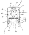
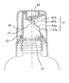
図6及び図7に、本発明の第2実施例の注出キャップの構造を示した。即ち、図6は、第2実施例の注出キャップの側断面をオーバーキャップ及び容器口部と共に示す図であり、図7は、図6の注出キャップの側面(オーバーキャップを取り除いた状態)を示す図である。
尚、これら図の注出キャップ乃至複合容器蓋は、環状体5(外筒11)の平断面外形が楕円形である等、基本的な構造は第1実施例と同じであるため、第1実施例と異なる部分及びその説明に必要な部分のみを印照数字で示した。
また、図6は、上記楕円形の長軸上での断面を示すものである。
【0036】
第1実施例の注出キャップ1においては、環状体5と注出筒6とが一体に形成されているが、第2実施例では、この環状体5と注出筒6とは、別体に形成されている。即ち、環状体5の上端の水平フランジ12の上面には、周状突起50が形成されており、注出筒6の筒状側壁25の下端には、上記周状突起50に対応する凹部が形成されており、この凹部内に周状突起50を嵌め込むことにより、注出筒6と環状体5とが結合される。
このように環状体5と注出筒6とを別体にすることにより、環状体5を比較的剛性のプラスチックで形成し、且つ注出筒6を弾性の大きい柔軟性に富んだプラスチックで形成することができる。
また第1の実施例のように、環状体5と注出筒6とを一体に形成した場合には、型抜きのために、筒状側壁25の内面と、水平フランジ12の内周縁とは直線状に形成されていることが必要である。しかしながら、第2実施例のように環状体5と注出筒6とを別体で形成した場合には、上記のような型抜き上の制限はないため、筒状側壁25の内面と水平フランジ12の内周縁との間には、段差51が形成されている。従って、筒状側壁25の内径を可及的に大きく設定することができ、ベース傾斜壁30を大きくし、弾性圧潰部31の容積を大きくすることができる。即ち、1回の圧潰操作によって注出される液量を多くすることができ、これは第2実施例の優れた利点である。
【0037】
さらに第2実施例においては、注出筒6の筒状側壁25に形成されているベース傾斜壁30上の弾性圧潰部31が多段となっている。即ち、この圧潰部31は、2個の半筒状の直立壁40a,40bと、2個の可撓性傾斜壁41a,41bとが交互に連なっている。
即ち、ベース傾斜壁30上からは、第1の直立壁40aが立ち上がっており、この直立壁40aの上端は第1の可撓性傾斜壁41aで閉じられ、この可撓性傾斜壁41a上からは第2の直立壁40bが立ち上がっており、直立壁40bの上端は第2の可撓性傾斜壁41bで閉じられている。また第1の直立壁40a及び第2の直立壁40bは,何れも、その両端の高さが実質上ゼロであり、この部分で頂壁26に連なっている。さらに第1の可撓性傾斜壁41a及び第2の可撓性傾斜壁41bの何れも、その上端部分で頂壁26に連なっている。
更に第1の可撓性傾斜壁41aの傾斜角は、ベース傾斜壁30の傾斜角αよりも小さく、第2の可撓性傾斜壁41bの傾斜角は、第1の可撓性傾斜壁41aの傾斜角よりもさらに小さくなっている。
従って、押圧片43を押し込んでいくと、第2の可撓性傾斜壁41b,第1の可撓性傾斜壁41a,第2の直立壁40b,ベース傾斜壁30の内周部及び第1の直立壁40aの順に圧潰がスムーズに進行し、押圧片43の裏面がベース傾斜壁30の外周縁に密着することにより、圧潰が終了することになる。
【0038】
このように、弾性圧潰部31を多段にすることによる大きな利点は、弾性圧潰部31の容積を大きくし、1回の圧潰により注出される液の量を多くできる点にある。即ち、第1実施例の図1を参照すると、弾性圧潰部31の容積を最大にするためには、可撓性傾斜壁41の傾斜角βをゼロ(傾斜壁41が水平面となる)にすればよい。しかしながら、この場合には、壁41が傾斜していないため、弾性圧潰部31を圧潰させることが困難となってしまう。しかるに、第2実施例に示されている様に、弾性圧潰部31を多段にすることにより、圧潰部31の圧潰性を損なうことなく、その容積を可及的に大きくし、1回の圧潰操作による注出液量を増量することが可能となるものである。
尚、図6及び7の例では、弾性圧潰部31が2段に形成されているが、筒状側壁25の内径に応じて、これを3段或いはそれ以上の段とすることも勿論可能である。
また、第2実施例においても、第1実施例と同様、直立壁40a,40bの厚みは、ベース傾斜壁30の内周部,可撓性傾斜壁41a,41bの厚みよりも厚くすることが好適である。
【0039】
(第3実施例)
図8には、第3実施例の注出キャップの側断面を、オーバーキャップ及び容器口部と共に示した。
この注出キャップは、パッキンが使用されていない点を除けば、第1実施例のと実質的に同じである。即ち、この例では、内筒10の内面にパッキン保持用の周状突起16は形成されておらず、さらに水平フランジ12の内周縁からは比較的肉厚の下方突起60が設けられている。この肉厚の下方突起60が直接容器口部100の上端に圧接することにより、良好なシール性が確保される。
また、この態様においては、上記下方突起60の下端に、周状の小突起61を設けることが好ましい。かかる小突起61により、容器口部100の上端への圧接力を高め、シール性をさらに向上させることができる。
尚、第3実施例の注出キャップ1に装着されるオーバーキャップ2においては、天板35の内面に設けられている2個の閉塞突起38,38は、注出パイプ27の上端外周面と密着して注出パイプ27の上端を閉じるようになっている。
【0040】
(その他の実施例)
上述した第1乃至第3実施例で示した具体例においては,種々の設計変更が可能である。例えば、第1実施例の注出キャップ1において、その弾性圧潰部31を、第2実施例で示した様に多段とすることができるし、その環状体5と注出筒6とを第2実施例で示した様に別体で形成することもできる。また、第2実施例の注出キャップ1において、第3実施例で示した様に、パッキンを用いないでシール性を確保する構造とすることもできる。
更に、第1乃至第3実施例では、環状体5及びオーバーキャップ2の平断面外形が楕円形となっているが、これを容器の形状に応じて、これを円形とすることも可能である。この場合、環状体5の側断面は、例えば図2で示したような形状となる。また、注出筒6に設けられている注出パイプ27は、環状体5の中心(容器口部100の中心に相当)に位置させることが好ましく、従って、オーバーキャップ2の閉塞突起38は、天板35の中心に1個形成しておくのがよい。但し、この場合は、ベース傾斜壁30を大きくすることが困難となり、弾性圧潰部31の容積を大きくすることができないため、1回の圧潰により排出される内容液の量を多量にするという点では好ましくない。さらにオーバーキャップ2の平断面形状を円形としつつ、注出パイプ27を偏心位置に形成させる場合には、閉塞突起38と注出パイプ27とが嵌合するように、何らかの位置決め機構を、オーバーキャップ2と環状体5との間に設けることが必要となる。
また第1乃至第3実施例において、弾性圧潰部31を構成する直立壁40等は若干傾斜していてもよく、また頂壁26を多少傾斜させることも可能である。
【0041】
(容器蓋素材)
本発明において、上述した種々の構造の注出キャップ及びオーバーキャップから成る複合容器蓋において、例えばオーバーキャップの成形に用いる樹脂としては、低−,中−又は高−密度ポリエチレン、線状低密度ポリエチレン、ポリプロピレン、熱可塑性ポリエステル、ポリアミド、スチレン系樹脂、ABS樹脂等の各種プラスチックを用いることができる。また、第1実施例に示されている様な環状体と注出筒とが一体に形成された注出キャップを成形するためには、弾性を有する圧潰部を形成することが必要であるため、上記の各種プラスチック、例えばポリプロピレンに、各種ゴム乃至熱可塑性エラストマーを配合したものが使用される。また、第2実施例に示されている様に、環状体と注出筒とが別体で形成されている場合、環状体は、ポリプロピレンなどの上記各種プラスチックで成形し、注出筒は,各種ゴムや熱可塑性エラストマーで成形するのがよい。さらに第1及び第2実施例で用いられるパッキンは、低密度ポリエチレン、エチレン系重合体、各種ゴム乃至熱可塑性エラストマー、アクリル樹脂プラスチゾル、塩化ビニル樹脂プラスチゾル等を用いて成形することができる。
【0042】
【発明の効果】
本発明の注出キャップは、容器内容液の注出を行うためにの弾性圧潰部がベース傾斜壁上に形成されており、このベース傾斜壁の大きさは容器口部径によって制限されず、容器口部径が小さくとも、このベース傾斜壁を大きく設定することにより、弾性圧潰部の容積を大きくし、1回の圧潰により注出される液量を多くすることができる。従って、本発明の注出キャップは、特に小容量の化粧品などの容器に有効に適用される。
また本発明では、上記弾性圧潰部を、ベース傾斜壁から軸方向に延びている半筒状の軸方向壁(直立壁)と、該軸方向壁の上端を閉じる様に形成されている可撓性傾斜壁とから形成することにより、圧潰性を高め、圧潰された弾性圧潰部を元の形状に瞬時に弾性復帰させることができる。特に弾性復帰が瞬時に行われることにより、注出パイプに残存或いは付着した内容液を容器内に迅速に戻すことが可能となるため、注出パイプ上端からの液垂れを有効に防止できる。さらに、上記軸方向壁の厚みを、ベース傾斜壁の内周部及び軸方向壁上端の傾斜壁の厚みよりも厚くすることにより、上記の弾性復帰機能を高め、液垂れ等の防止性能を一層向上させることができる。
【図面の簡単な説明】
【図1】第1実施例の注出キャップの全体構造を、オーバーキャップ及び容器口部と共に示す側断面図。
【図2】図1とは90度異なる方向からみた注出キャップの一部断面、一部側面をオーバーキャップ及び容器口部と共に示す図。
【図3】注出キャップの上面を容器と共に示す図。
【図4】図1に示されている注出キャップの側面を、オーバーキャップの側断面と共に示す図。
【図5】図1の注出キャップと組合せで使用されるオーバーキャップの上面を示す図。
【図6】第2実施例の注出キャップの側断面を、オーバーキャップ及び容器口部と共に示す図。
【図7】図6の注出キャップの側面を示す図。
【図8】第3実施例の注出キャップの側断面を、オーバーキャップ及び容器口部と共に示す図。
【符号の説明】
2:オーバーキャップ 5:環状体
6:注出筒 10:内筒
11:外筒 12:水平フランジ
20:水平段差部 25:筒状側壁
26:頂壁 27:注出パイプ
30:ベース傾斜壁 31:弾性圧潰部
40:半筒状直立壁 41:可撓性傾斜壁
43:押圧片[0001]
BACKGROUND OF THE INVENTION
The present invention relates to a pouring cap having a pouring function, and more specifically, used as a cap for glass containers, rigid plastic containers, metal containers, etc., by crushing a part thereof, The present invention relates to a dispensing cap capable of dispensing a certain amount of content liquid.
[0002]
[Prior art]
A container lid used for a glass container, a rigid plastic container, or the like is composed of an inner stopper attached to the container mouth portion and provided with a dispensing hole, and an overcap provided so as to cover the inner stopper. The one which pours the contents liquid from the hole for pouring the inside plug by shaking upside down is widely used. This type of container lid is widely applied to containers filled with cosmetic liquids such as hairdressing agents and perfumes, but has a drawback that the inner plug becomes dirty due to dripping. Further, since the content liquid is discharged by shaking the container upside down, the amount of liquid discharged is not constant, and there is a further disadvantage that the liquid is easily spilled.
[0003]
As a container lid that has improved the drawbacks of the container lid as described above, Japanese Utility Model Laid-Open No. 6-81964, etc. is provided with a pipe or nozzle for pouring the contents upright on the top surface of the inner plug, and a dome on the top surface. It has been proposed to provide a raised portion in a shape. That is, in this container lid, the container is turned upside down, and the dome-shaped raised portion is pressed and crushed (recessed), whereby the content liquid is discharged from the pipe or nozzle for pouring. Accordingly, the amount of liquid discharged corresponds to the volume of the recessed dome-shaped ridge, and there is an advantage that a substantially constant amount of liquid can be discharged. Further, due to the elastic return of the recessed dome-shaped bulge, outside air is sucked into the container from the pipe or nozzle for pouring, and thereby dripping can be effectively prevented.
[0004]
[Problems to be solved by the invention]
However, the container lid disclosed in the above prior art has a problem that it is difficult to apply to a container having a small container opening, for example, a small container such as cosmetics carried in a bag or the like.
That is, in the container lid used for such a container, the top surface of the inner plug attached to the container mouth is inevitably considerably small, and a pipe or nozzle for dispensing and a dome are placed in the top surface of this small area. Both ridges must be formed. Therefore, the dome-shaped ridges must also be extremely small, and as a result, the dome-shaped ridges cannot have a sufficient dent volume, and it becomes difficult to discharge a sufficient amount of liquid. This is because the crushing operation must be repeated many times in order to take out the amount of liquid.
In addition, when the dome-shaped bulge is crushed and dented, it is difficult to return to its original shape, and there is a problem that the dripping prevention function is insufficient. The larger the value, the more prominent. In other words, when the dome raised portion is pressed and recessed, the dome-shaped wall portion is completely reversed and easily becomes a stable shape. For this reason, the recessed shape does not easily return to its original shape, and the dripping prevention function is unsatisfactory. It will be something. Accordingly, the dome-shaped bulging portion must be small in shape, and the amount of liquid dispensed by one crushing becomes smaller and smaller in order to prevent liquid dripping by elastic recovery. Furthermore, the smaller the dome-shaped raised portion, the more difficult it is to perform the crushing operation of the dome-shaped raised portion for discharging the liquid.
[0005]
Accordingly, an object of the present invention is to provide a dispensing cap that can discharge a sufficient amount and a constant amount of liquid stably by a single crushing of the cap, and can be applied to a container having a small container opening. Is to provide.
Another object of the present invention is to easily perform elastic deformation by crushing the cap for discharging the liquid contained in the container, and the elastic deformation of the elastically deformed portion is instantaneously performed. An object of the present invention is to provide a dispensing cap in which problems such as dripping are effectively prevented.
[0006]
[Means for Solving the Problems]
According to the present invention,
In a pouring cap comprising an annular body that is held and fixed to the container mouth portion and provided with an annular horizontal flange at the upper end, and an ejection cylinder provided on the annular body,
The dispensing cylinder includes a cylindrical side wall having a lower end connected to the horizontal flange of the annular body, and an upper end surface formed by the upper end of the cylindrical side wall has a top wall and the top wall An inclined base wall inclined downward is formed on the top wall, and a pouring pipe that communicates with the cylindrical side wall inner space and stands upright is provided on the base inclined wall. Provided protrudingAnd
The crushing portion is formed in a plurality of stages by alternately connecting at least two semi-cylindrical upright walls and two flexible inclined walls, and the first upstanding wall is formed on the base inclined wall. The upper end of the first upright wall is closed by the first flexible inclined wall, and the second upright wall rises from above the first flexible inclined wall, and the second upright wall The upper end is closed with a second flexible inclined wall, and the first flexible inclined wall and the second flexible inclined wall are each connected to the top wall at the upper end portion.
A dispensing cap is provided.
[0007]
In the above-mentioned pouring cap, the content liquid can be easily discharged by tilting the container in which the cap is mounted and pressing and crushing the elastic crushing portion formed on the base inclined wall of the cylindrical side wall. It can be carried out. In other words, a certain amount of liquid is discharged from the dispensing pipe corresponding to the volume of the elastic crushing portion recessed by this pressing. Therefore, a constant amount of liquid can be always discharged by one crushing, and the amount of liquid can be adjusted by adjusting the pressing force to adjust the depression of the elastic crushing portion.
Furthermore, if the pressing force is released, the depressed crushing portion is elastically restored to its original shape, and dripping or the like is effectively prevented by the inflow of outside air from the extraction pipe.
[0008]
In the present invention, the most important feature is that an elastic crushing portion for pouring out the liquid is formed on the inclined wall (base inclined wall), whereby the dispensing cap is connected to the mouth portion. It is possible to apply to a container having a small diameter.
That is, when an elastic crushing portion is formed on the horizontal wall of the pouring cylinder, the horizontal wall is naturally smaller than the diameter of the container mouth, and the pouring pipe must be provided on the horizontal wall. . Therefore, the elastic crushing portion is also small, and it is difficult to apply such a container lid to a container having a small opening diameter.
In particular, when the base inclined wall is formed on the cylindrical side wall of the dispensing cylinder according to the present invention and the elastic crushing portion is formed on the base inclined wall, the size of the base inclined wall is the size of the container. Regardless of the diameter of the mouth portion, the base inclined wall can be enlarged by adjusting the length of the cylindrical side wall and the inclination angle of the base inclined wall. In other words, even when a pouring pipe is provided at the upper end of the pouring cylinder or when applying to a container having a small opening diameter, the volume of the elastic crushing portion is increased by setting the base inclined wall large. As a result, the amount of the content liquid poured out by pressing the elastic crushing portion can be increased and the pressing operation can be easily performed.
Thus, the pouring cap of the present invention can be applied to a container having a small opening diameter, which is a great advantage of the present invention.
In addition, the special shape of the elastic crushing part formed on the inclined base wall makes it possible to instantaneously return the crushed elastic crushing part back to its original shape, thereby significantly improving the dripping prevention function. This is a great advantage of the present invention.
[0009]
In the present invention, since the base inclined wall described above is formed at the upper end of the cylindrical side wall, the top wall formed at the upper end of the cylindrical side wall is usually a crescent with a part of a circle cut out. It becomes a shape, and a pouring pipe for pouring the content liquid is provided on the crescent-shaped top wall.
Further, the pouring cap of the present invention is usually used as a composite container lid in combination with an overcap engaged and fixed to the annular body of the pouring cap so as to cover the pouring cylinder of the cap. . The overcap is formed of a top plate and a skirt portion that hangs down from the periphery of the top plate. When the overcap is engaged and fixed to the annular body on the inner surface of the top plate, A closing projection for closing the upper end of the dispensing pipe is formed. Good sealing performance can be maintained by the engagement between the closing protrusion and the upper end of the dispensing pipe. For example, when the pouring pipe is not set upright, it is difficult to seal with such a closing projection.
As described above, the composite container lid in which the above-described dispensing cap is combined with the overcap can be applied to a container that is particularly required to be sealed, such as a cosmetic container that is carried in a bag. Is also a great advantage of the present invention.
[0010]
DETAILED DESCRIPTION OF THE INVENTION
In the present invention, the annular body that is held and fixed to the container mouth and the dispensing cylinder that includes the dispensing pipe for dispensing the container liquid can be formed integrally, or both They can be formed as separate members and used in combination.
When the annular body and the dispensing cylinder are integrally formed, the number of parts constituting the dispensing cap is reduced, so that there is an advantage that the production process is simplified.
On the other hand, when the annular body and the dispensing cylinder are formed as separate members, the number of components increases, but there is an advantage that the annular body and the dispensing cylinder can be formed of different plastics. . That is, the annular body is held and fixed to the container mouth by means such as fitting or screw fixing, so it is preferable to form it with a relatively rigid and high strength plastic. Since the cylinder has an elastic crushing portion, it is preferable to form the cylinder with a flexible plastic. It is an advantage of this aspect that the annular body and the dispensing cylinder can be formed of different plastics according to such characteristics.
In addition, when the annular body and the dispensing cylinder are integrally formed, the inner peripheral surface of the cylindrical side wall of the dispensing cylinder is aligned with the inner peripheral surface of the horizontal flange of the annular body for die cutting after the completion of molding. Therefore, the inner diameter of the dispensing cylinder (cylindrical side wall) is limited, but when the annular body and the dispensing cylinder are separated, the size for such die cutting There are no restrictions. That is, the inner diameter of the dispensing cylinder (cylindrical side wall) can be increased, and thus the volume of the elastic crushing part can also be increased. As a result, the amount of content liquid dispensed by one crushing can be reduced. There is also the advantage that you can do more.
[0011]
When the annular body and the dispensing cylinder are separated, an appropriate projection is provided on the upper surface of the horizontal flange of the annular body, and the projection is used to engage the lower end of the cylindrical side wall of the dispensing cylinder. Both can be combined by fitting or fitting.
Moreover, a horizontal flange can be provided in the lower end of a cylindrical side wall, and both can also be couple | bonded by pinching this horizontal flange between the horizontal flange of a cyclic | annular body, and a container mouth part upper end. In this case, since the cylindrical body is formed of a flexible plastic, the horizontal flange at the lower end of the cylindrical side wall functions as a packing, and as a result, the sealing performance can be improved.
[0012]
In the present invention, the elastic crushing portion formed on the base inclined wall connected to the top wall at the upper end of the cylindrical side wall rises from the base inclined wall and extends in the axial direction, and the upper end is inclined at a certain angle. It is preferable to form it from a cylindrical axial side wall and a flexible inclined wall formed so as to close the upper end of the axial side wall. In this case, both ends in the circumferential direction of the axial side wall are substantially zero in height and are connected to the top wall at this portion, and the flexible inclined wall has an inclination angle formed by the base inclined wall and the horizontal plane. It continues to the top wall at a smaller angle.
[0013]
When the shape of the elastic crushing portion is as described above, when the flexible inclined wall of the crushing portion is pressed, the flexible inclined wall and the axial side wall both have a boundary with the top wall at the upper end as a fulcrum. Since it dents downward, crushing proceeds smoothly. In addition, since the concave shape of the elastic crushing portion is an unstable irregular shape, when the pressing force is released, the elastic shape is instantaneously restored to the original shape. Accordingly, the liquid remaining or adhering to the dispensing pipe is immediately collected in the container, and dripping or the like is effectively prevented. Moreover, when discharging the content liquid by pressing the elastic crushing portion, since a relatively large force is required when the axial side wall is recessed, there is an advantage that an appropriate tactile sensation is given to the operator.
For example, when this crushing part is formed in a dome shape, the shape recessed by crushing tends to be a stable dome reversal shape, so even if the pressing force is released, it is difficult to return to the original shape and work when crushing However, such a problem is effectively solved by making the elastic crushing part into the shape described above.
In addition, when the shape of the elastic crushing part is as described above, a sound is generated when the crushing part is crushed and when it is restored to the original shape. And the commercial value of the container is increased.
[0014]
In the present invention, the thickness of the axial side wall of the elastic crushing portion is set to be larger than the thickness of the inner peripheral portion of the base inclined wall (near the base of the axial side wall) and the flexible inclined wall at the upper end of the axial side wall. It is preferable to make it thick. Thereby, since the self-supporting property of the axial side wall is strengthened, the elastic restoring force of the elastic crushing portion when crushing is further enhanced, and the dripping prevention function can be further enhanced.
[0015]
In the present invention, the elastic crushing portion can be formed in a multistage shape by alternately connecting the semi-cylindrical axial side wall and the flexible inclined wall connected to the upper end of the axial side wall.
As the volume of the hollow elastic crushing part formed on the base inclined wall is increased, the amount of liquid dispensed by one crushing can be increased, and the horizontal surface of the flexible inclined wall connected to the upper end in the axial direction side wall. As the tilt angle (corresponding to the tilt angle of the upper end of the axial side wall) approaches zero (closer to the horizontal plane), the volume of the elastic crushing portion increases. However, as the inclination angle of the flexible inclined wall approaches zero, it becomes difficult to smoothly dent the elastic crushing portion (decrease in crushing property). However, as described above, by forming the elastic crushing portion in multiple stages, the internal volume of the elastic crushing portion can be increased as much as possible without impairing the crushability.
[0016]
Further, in the above-described elastic crushing portions having various structures, the elastic crushing portion is crushed on the uppermost flexible inclined wall connected to the top wall of the upper end of the cylindrical side wall, particularly on the upper end portion of the flexible inclined wall. It is preferable to provide a pressing piece for this purpose. By pressing such a pressing piece against the base inclined wall, the elastic crushing portion can be smoothly crushed and the content liquid can be easily poured out. In this case, the operator can confirm the end of the extraction work when the pressing piece comes into contact with the base inclined wall.
[0017]
The pouring pipe provided on the top wall where the flexible inclined wall and the semi-cylindrical axial side wall of the elastic crushing part are connected is arranged at the center of the container mouth, that is, the center of the pouring cylinder. However, it is particularly preferably formed at a position eccentric from the center thereof. By forming the pouring pipe at such an eccentric position, the top wall can be made as small as possible, and the aforementioned base inclined wall can be made as large as possible. This is advantageous in increasing the amount of liquid discharged by crushing.
[0018]
In addition, when the dispensing cap having the structure described above is used as a composite container lid in combination with an overcap, the overcap is annularly formed on the top plate inner surface of the overcap because the dispensing pipe is provided upright. A closing protrusion can be provided that closes the upper end of the dispensing pipe when it is engaged and fixed to the body to cover the dispensing cylinder. The closing protrusion may be fitted into the upper end of the pouring pipe, or may be formed into an annular shape so that the upper end of the pouring pipe is fitted into the inside.
[0019]
In the above composite container lid, the annular body and the overcap increase the commercial value by making the overcap appear to be an integrated article in appearance with the overcap engaged and fixed to the annular body. Preferred above. For this reason, the annular body and the overcap preferably have substantially the same outer shape when viewed from the upper surface in a state where both are engaged and fixed. Moreover, when the horizontal cross-sectional shape of the trunk | drum of a container is an ellipse, it is good for both said external shapes to also be an ellipse.
Furthermore, when the outer shape of the overcap as viewed from the top is an ellipse, two of the above-described blocking protrusions are formed, and these blocking protrusions are lined up with each other on the major axis of the ellipse and the minor axis as a center. It is preferable to arrange in a symmetrical position. By providing two closing projections at such a position, it becomes possible to reliably close the upper end of the pouring pipe when the annular cap is engaged in any direction of the overcap. There is no need for alignment when mounting, improving workability.
In addition, when the shape of the overcap as viewed from the top is circular, it is usually better to set the pouring pipe at the center of the container mouth, and pouring it at a position eccentric from the center of the container mouth. When the outlet pipe is arranged, it is necessary to provide a special positioning mechanism in order to securely close the upper end of the outlet pipe by the closing protrusion.
[0020]
In the above-described dispensing cap or composite container lid, the annular body is attached to the container mouth portion by fitting or screw engagement. From the standpoint of separating and discarding the used container lid from the container, the screw It is preferable to have a structure that is attached to the container mouth by engagement.
Furthermore, it is preferable that the annular body includes an inner cylinder having a thread on the inner surface and an outer cylinder positioned outside the inner cylinder. That is, when the annular body is fixed to the container mouth portion by screw engagement, the shape of the outer peripheral surface of the container mouth portion having a thread is a cylinder, so the portion having the thread of the annular body is also a cylinder. . However, the body shape of the container is not limited to a cylinder, and there is also a container having a body having a flat shape such as an elliptical cross section. For example, because it has the advantage of being able to see the label affixed to the barrel well, many small-volume containers have such flat-shaped barrels, This is particularly common in the cosmetics field. Therefore, by configuring the annular body screwed to the container mouth portion from the outer cylinder and the inner cylinder provided with the thread as described above, even if the inner cylinder is cylindrical, the lower end of the outer cylinder The outer shape of the container can be smoothly continued to the shape of the container shoulder (portion extending from the trunk to the mouth). That is, regardless of the shape of the container body, the outer shape of the annular body can be continued to the shape of the container shoulder, and the container lid can be seen as a part of the container. In the field of cosmetics and the like that can increase the commercial value of the container, and in particular, the appearance of the container is required, a pouring cap provided with an annular body having such a double wall structure of an inner cylinder and an outer cylinder or A composite container lid is extremely useful.
[0021]
In such a double-walled annular body, the upper end of the inner cylinder is connected to the inner surface of the horizontal flange, and the upper end of the outer cylinder is connected to the outer peripheral edge of the horizontal flange. A horizontal stepped portion is preferably formed in the middle of the outer cylinder, and a protrusion for locking the overcap is formed on the outer peripheral surface of the outer cylinder above the horizontal stepped portion.
That is, the structure is such that the overcap is locked and fixed to the annular protrusion formed in such a position, and the overcap has the same shape as the outer shape of the container shoulder. The composite container lid and the container are observed as a whole as a whole in appearance, and the commercial value is remarkably increased.
[0022]
【Example】
Hereinafter, the present invention will be described in detail based on specific examples shown in the accompanying drawings.
(First embodiment)
1 to 5 show a first embodiment of a dispensing cap according to the present invention. FIG. 1 shows the entire structure of the dispensing cap of the first embodiment together with an overcap and a container mouth. FIG. 2 is a side sectional view, and FIG. 2 is a view showing a partial cross section and a partial side view of the pouring cap as viewed from a direction different from that of FIG. It is a figure which shows the upper surface (state which removed the overcap) of the output cap with a container, and FIG. 4 shows the side surface of the extraction cap (integral molding of an annular body and an extraction cylinder) shown by FIG. FIG. 5 is a view showing a side cross-section of the overcap, and FIG. 5 is a view showing an upper surface of the overcap attached to the dispensing cap of FIG. 1.
The side cross section of the extraction cap shown in FIG. 1 corresponds to the II cross section of FIG. 3, and the side cross section (partial side surface) of the extraction cap shown in FIG. It corresponds to the II-II cross section.
[0023]
With particular reference to FIGS. 1, 2, and 4, the dispensing cap generally indicated by 1 is used in combination with the
The pouring cap 1 is composed of an annular body 5 screwed to the
[0024]
The annular body 5 includes an
[0025]
An inner surface of the
Further, on the inner surface of the
[0026]
As is clear from FIG. 1, a horizontal stepped
Further, as apparent from the top view of FIG. 3, the outer shape of the
[0027]
The dispensing
Further, a part of the upper end of the
Further, an elastic crushing
[0028]
The
[0029]
Furthermore, two
By the way, the above-described
The closing
[0030]
In the above-described pouring cap 1 of the present invention, the elastic crushing
[0031]
A
That is, the elastic crushing
[0032]
In such an embodiment, since the crushing
[0033]
Further, when the
[0034]
In such a pouring cap 1 of the present invention, it is preferable that the thickness of the
[0035]
(Second embodiment)
6 and 7 show the structure of the dispensing cap of the second embodiment of the present invention. That is, FIG. 6 is a view showing a side cross section of the pouring cap of the second embodiment together with the overcap and the container mouth portion, and FIG. 7 is a side view of the pouring cap of FIG. 6 (a state where the overcap is removed). FIG.
In addition, since the basic structure of the pouring cap or the composite container lid in these drawings is the same as that of the first embodiment, such as the outer shape of the annular body 5 (outer cylinder 11) being elliptic, the first structure is the same as the first embodiment. Only the parts different from the examples and the parts necessary for the description are indicated by imprinted numerals.
FIG. 6 shows a cross section on the major axis of the ellipse.
[0036]
In the pouring cap 1 of the first embodiment, the annular body 5 and the pouring
Thus, by making the annular body 5 and the
When the annular body 5 and the
[0037]
Furthermore, in the second embodiment, the elastic crushing
That is, the first
Furthermore, the inclination angle of the first flexible inclined wall 41a is smaller than the inclination angle α of the base inclined
Accordingly, when the
[0038]
Thus, the big advantage by making the elastic crushing
In the example of FIGS. 6 and 7, the elastic crushing
Also in the second embodiment, as in the first embodiment, the thickness of the
[0039]
(Third embodiment)
In FIG. 8, the side cross section of the extraction | pouring cap of 3rd Example was shown with the overcap and the container opening part.
This dispensing cap is substantially the same as that of the first embodiment except that no packing is used. In other words, in this example, the
In this embodiment, it is preferable to provide a circumferential small protrusion 61 at the lower end of the
In the
[0040]
(Other examples)
In the specific examples shown in the first to third embodiments described above, various design changes are possible. For example, in the pouring cap 1 of the first embodiment, the elastic crushing
Further, in the first to third embodiments, the planar cross-sectional outlines of the annular body 5 and the
In the first to third embodiments, the
[0041]
(Container lid material)
In the present invention, in the composite container lid composed of the above-described pouring cap and overcap having various structures, for example, the resin used for molding the overcap may be low-, medium- or high-density polyethylene, linear low-density polyethylene. Various plastics such as polypropylene, thermoplastic polyester, polyamide, styrene resin, and ABS resin can be used. Moreover, in order to shape | mold the extraction cap in which the annular body and extraction pipe | tube which were shown by 1st Example were integrally formed, it is necessary to form the crushing part which has elasticity. The above-mentioned various plastics, for example, polypropylene blended with various rubbers or thermoplastic elastomers are used. Further, as shown in the second embodiment, when the annular body and the dispensing cylinder are formed separately, the annular body is molded from the above-mentioned various plastics such as polypropylene, It is preferable to mold with various rubbers and thermoplastic elastomers. Further, the packing used in the first and second embodiments can be molded using low density polyethylene, ethylene polymer, various rubbers or thermoplastic elastomers, acrylic resin plastisol, vinyl chloride resin plastisol, or the like.
[0042]
【The invention's effect】
In the pouring cap of the present invention, an elastic crushing portion for pouring the liquid in the container is formed on the base inclined wall, and the size of the base inclined wall is not limited by the container mouth diameter, Even if the diameter of the container opening is small, by setting the base inclined wall large, the volume of the elastic crushing portion can be increased and the amount of liquid dispensed by one crushing can be increased. Therefore, the dispensing cap of the present invention is effectively applied to containers such as cosmetics with a small capacity.
In the present invention, the elastic crushing portion is formed by closing the semi-cylindrical axial wall (upright wall) extending in the axial direction from the base inclined wall and the upper end of the axial wall. By forming it from the inclined wall, it is possible to enhance the crushability and to instantaneously return the crushed elastic crushing portion to its original shape. In particular, since the elastic recovery is instantaneously performed, it is possible to quickly return the content liquid remaining on or adhering to the extraction pipe into the container, so that dripping from the upper end of the extraction pipe can be effectively prevented. Furthermore, by making the thickness of the axial wall thicker than the thickness of the inner peripheral part of the base inclined wall and the inclined wall at the upper end of the axial wall, the above-described elastic return function is enhanced, and the ability to prevent liquid dripping is further improved. Can be improved.
[Brief description of the drawings]
FIG. 1 is a side sectional view showing an overall structure of a dispensing cap according to a first embodiment together with an overcap and a container mouth portion.
FIG. 2 is a view showing a partial cross-section and a partial side surface of the pouring cap viewed from a direction different from 90 ° from FIG. 1 together with an overcap and a container mouth portion.
FIG. 3 is a view showing an upper surface of a dispensing cap together with a container.
FIG. 4 is a view showing a side surface of the dispensing cap shown in FIG. 1 together with a side cross section of the overcap.
5 is a view showing an upper surface of an overcap used in combination with the dispensing cap of FIG. 1. FIG.
FIG. 6 is a view showing a side cross section of a dispensing cap according to a second embodiment together with an overcap and a container mouth portion.
7 is a view showing a side surface of the dispensing cap of FIG. 6. FIG.
FIG. 8 is a view showing a side cross section of the pouring cap of the third embodiment together with an overcap and a container mouth portion.
[Explanation of symbols]
2: Overcap 5: Ring
6: Injection cylinder 10: Inner cylinder
11: outer cylinder 12: horizontal flange
20: Horizontal step part 25: Cylindrical side wall
26: Top wall 27: Extraction pipe
30: Base inclined wall 31: Elastic crushing part
40: Semi-cylindrical upright wall 41: Flexible inclined wall
43: Pressing piece
Claims (5)
前記注出筒は、下端部が前記環状体の水平フランジに接続された筒状側壁を備えており、前記筒状側壁の上端部によって形成される上端面には、頂壁と、該頂壁から下方に傾斜したベース傾斜壁とが形成されており、該頂壁上に、筒状側壁内空間と通じ且つ直立した注出パイプが設けられ、該ベース傾斜壁上には、弾性の圧潰部が突出して設けられ、
該圧潰部は、少なくとも2個の半筒状の直立壁と、2個の可撓性傾斜壁とが交互に連なって複数段に形成され、該ベース傾斜壁上からは第1の直立壁が立ち上がり、該第1の直立壁の上端は第1の可撓性傾斜壁で閉じられ、該第1の可撓性傾斜壁上からは第2の直立壁が立ち上がり、該第2の直立壁の上端は第2の可撓性傾斜壁で閉じられ、該第1の可撓性傾斜壁及び該第2の可撓性傾斜壁は、それぞれ上端部分で該頂壁に連なっている、
ことを特徴とする注出キャップ。In a pouring cap comprising an annular body that is held and fixed to the container mouth portion and provided with an annular horizontal flange at the upper end, and an ejection cylinder provided on the annular body,
The dispensing cylinder includes a cylindrical side wall having a lower end connected to the horizontal flange of the annular body, and an upper end surface formed by the upper end of the cylindrical side wall has a top wall and the top wall An inclined base wall inclined downward is formed on the top wall, and a pouring pipe that communicates with the cylindrical side wall inner space and stands upright is provided on the base inclined wall. Is provided protruding,
The crushing portion is formed in a plurality of stages by alternately connecting at least two semi-cylindrical upright walls and two flexible inclined walls, and the first upstanding wall is formed on the base inclined wall. The upper end of the first upright wall is closed by the first flexible inclined wall, and the second upright wall rises from above the first flexible inclined wall, and the second upright wall The upper end is closed with a second flexible inclined wall, and the first flexible inclined wall and the second flexible inclined wall are each connected to the top wall at the upper end portion.
A pouring cap characterized by that.
前記オーバーキャップは、天板と、天板の周縁から垂下しているスカート部とから形成されており、天板の内面には、該オーバーキャップを前記環状体に係合固定したときに、前記注出パイプの上端を閉じるための閉塞突起が形成され、
該オーバーキャップ及び環状体は、上面から見ての外形が、ほぼ同じ楕円形状を有しており、
該注出パイプは、前記楕円形状の長軸上に位置しており、
前記閉塞突起は2個形成されており、2個の閉塞突起は、前記楕円形状の長軸上に位置し且つ短軸を中心として互いに線対称となる位置に形成され、
前記閉塞突起は、オーバーキャップを閉じた時に、注出パイプ上端の内周面又は外周面と密着して該注出パイプ上端を閉じる、
ことを特徴とする複合容器蓋。A pouring cap comprising: an annular body that is held and fixed to the container mouth and has an annular horizontal flange at the upper end; and a pouring cylinder provided on the annular body, the pouring cylinder having a lower end Has a cylindrical side wall connected to the horizontal flange of the annular body, and an upper end surface formed by an upper end portion of the cylindrical side wall has a top wall and a base inclined wall inclined downward from the top wall. Doo is formed, on said top top wall is provided with a pouring pipe to and upstanding through the cylindrical side wall space, the base to the inclined upper wall, the crush of the elastic is found protrudes, the The crushing portion is formed in a plurality of stages by alternately connecting at least two semi-cylindrical upright walls and two flexible inclined walls, and the first upstanding wall rises from above the base inclined wall. , The upper end of the first upright wall is closed by a first flexible sloping wall, on the first flexible sloping wall. The second upright wall rises, the upper end of the second upright wall is closed by a second flexible inclined wall, and the first flexible inclined wall and the second flexible inclined wall are Each of the upper end portions is connected to the top wall, and the pouring pipe is formed at a position deviated from the center of the container mouth portion so as to cover the pouring cap and the pouring cylinder of the pouring cap. And an overcap that is engaged with and fixed to the annular body of the pouring cap,
The overcap is formed from a top plate and a skirt portion depending from the periphery of the top plate, and when the overcap is engaged and fixed to the annular body on the inner surface of the top plate, A closing projection for closing the upper end of the dispensing pipe is formed,
The overcap and the annular body have substantially the same elliptical shape as viewed from above.
The pouring pipe is located on the major axis of the elliptical shape,
Two closing protrusions are formed, and the two closing protrusions are located on the elliptical long axis and are symmetrical with each other about the short axis .
The closing protrusion closes the upper end of the extraction pipe in close contact with the inner or outer peripheral surface of the upper end of the extraction pipe when the overcap is closed ;
A composite container lid.
Priority Applications (1)
| Application Number | Priority Date | Filing Date | Title |
|---|---|---|---|
| JP28827798A JP4274604B2 (en) | 1998-10-09 | 1998-10-09 | Pouring cap |
Applications Claiming Priority (1)
| Application Number | Priority Date | Filing Date | Title |
|---|---|---|---|
| JP28827798A JP4274604B2 (en) | 1998-10-09 | 1998-10-09 | Pouring cap |
Publications (3)
| Publication Number | Publication Date |
|---|---|
| JP2000109109A JP2000109109A (en) | 2000-04-18 |
| JP2000109109A5 JP2000109109A5 (en) | 2005-10-27 |
| JP4274604B2 true JP4274604B2 (en) | 2009-06-10 |
Family
ID=17728099
Family Applications (1)
| Application Number | Title | Priority Date | Filing Date |
|---|---|---|---|
| JP28827798A Expired - Fee Related JP4274604B2 (en) | 1998-10-09 | 1998-10-09 | Pouring cap |
Country Status (1)
| Country | Link |
|---|---|
| JP (1) | JP4274604B2 (en) |
Families Citing this family (6)
| Publication number | Priority date | Publication date | Assignee | Title |
|---|---|---|---|---|
| JP4817221B2 (en) * | 2004-12-28 | 2011-11-16 | 株式会社吉野工業所 | Container with lid |
| JP5820690B2 (en) * | 2011-10-28 | 2015-11-24 | 株式会社吉野工業所 | Discharge pump |
| JP6328438B2 (en) * | 2014-02-19 | 2018-05-23 | キタノ製作株式会社 | Squeeze cap |
| DE102017107526A1 (en) | 2017-04-07 | 2018-10-11 | Linhardt Gmbh & Co. Kg | Case packaging |
| JP7471158B2 (en) * | 2020-06-30 | 2024-04-19 | 株式会社吉野工業所 | Discharge Cap |
| JP7455028B2 (en) * | 2020-08-31 | 2024-03-25 | 株式会社吉野工業所 | discharge cap |
Family Cites Families (6)
| Publication number | Priority date | Publication date | Assignee | Title |
|---|---|---|---|---|
| DE8713197U1 (en) * | 1986-10-03 | 1988-02-04 | Bramlage Gmbh, 2842 Lohne, De | |
| JPH0617753Y2 (en) * | 1987-04-03 | 1994-05-11 | 株式会社吉野工業所 | Cream-like material dispensing container |
| JPH078444Y2 (en) * | 1987-04-13 | 1995-03-01 | 株式会社吉野工業所 | Cream-like material dispensing container |
| US5810203A (en) * | 1991-11-08 | 1998-09-22 | Novapharm Research Pty. Limited | Pressure dispensing pump |
| JP2558868Y2 (en) * | 1995-02-10 | 1998-01-14 | 日本クラウンコルク株式会社 | Synthetic resin container lid with proper drainage function |
| JPH09150855A (en) * | 1995-12-01 | 1997-06-10 | Shiseido Co Ltd | Over-cap for pump dispenser |
-
1998
- 1998-10-09 JP JP28827798A patent/JP4274604B2/en not_active Expired - Fee Related
Also Published As
| Publication number | Publication date |
|---|---|
| JP2000109109A (en) | 2000-04-18 |
Similar Documents
| Publication | Publication Date | Title |
|---|---|---|
| US6029866A (en) | Multiple injection, toggle-action dispensing structure | |
| EP1371579B1 (en) | Valve mechanism for tube-type fluid container | |
| US5638995A (en) | Bellows container | |
| US5850953A (en) | Drip-free dispensing structure with collecting reservoir | |
| EP2424785B1 (en) | Toggle-action dispensing closure with articulated rear flange | |
| US10124936B2 (en) | Closure with lid and removable membrane | |
| JP4274604B2 (en) | Pouring cap | |
| JP3344501B2 (en) | Bottle-shaped container | |
| JPH1072052A (en) | Liquid discharging utensil | |
| JP3309119B2 (en) | Refill container | |
| JP3744613B2 (en) | Spray cover for aerosol container | |
| JPH11130035A (en) | Thin container | |
| JP3603110B2 (en) | Liquid dispense container | |
| JP2001010683A (en) | Liquid ejection container with pump | |
| JP4067743B2 (en) | Liquid dispensing container | |
| JP4022057B2 (en) | Synthetic resin sealed container | |
| JP3993759B2 (en) | Blow bottle | |
| JP4415696B2 (en) | Cap with tamper-evident prevention and separation / collection function | |
| JP4102454B2 (en) | Composite cap for aerosol containers | |
| JP2023018821A (en) | Cap with discharge valve | |
| JP2016120938A (en) | Composite liquid discharge cap capable of discharging by small amount | |
| JP2527507Y2 (en) | Liquid dispense container | |
| JPH0717777U (en) | Cap with dripping prevention mechanism | |
| JP3949327B2 (en) | Liquid discharge container | |
| EP0957035A1 (en) | Pour spout having dosing means |
Legal Events
| Date | Code | Title | Description |
|---|---|---|---|
| A521 | Written amendment |
Free format text: JAPANESE INTERMEDIATE CODE: A523 Effective date: 20050803 |
|
| A621 | Written request for application examination |
Free format text: JAPANESE INTERMEDIATE CODE: A621 Effective date: 20050803 |
|
| A131 | Notification of reasons for refusal |
Free format text: JAPANESE INTERMEDIATE CODE: A131 Effective date: 20080729 |
|
| A521 | Written amendment |
Free format text: JAPANESE INTERMEDIATE CODE: A523 Effective date: 20080929 |
|
| A131 | Notification of reasons for refusal |
Free format text: JAPANESE INTERMEDIATE CODE: A131 Effective date: 20081118 |
|
| A521 | Written amendment |
Free format text: JAPANESE INTERMEDIATE CODE: A523 Effective date: 20090115 |
|
| TRDD | Decision of grant or rejection written | ||
| A01 | Written decision to grant a patent or to grant a registration (utility model) |
Free format text: JAPANESE INTERMEDIATE CODE: A01 Effective date: 20090217 |
|
| A01 | Written decision to grant a patent or to grant a registration (utility model) |
Free format text: JAPANESE INTERMEDIATE CODE: A01 |
|
| A61 | First payment of annual fees (during grant procedure) |
Free format text: JAPANESE INTERMEDIATE CODE: A61 Effective date: 20090303 |
|
| R150 | Certificate of patent or registration of utility model |
Free format text: JAPANESE INTERMEDIATE CODE: R150 |
|
| FPAY | Renewal fee payment (event date is renewal date of database) |
Free format text: PAYMENT UNTIL: 20120313 Year of fee payment: 3 |
|
| FPAY | Renewal fee payment (event date is renewal date of database) |
Free format text: PAYMENT UNTIL: 20120313 Year of fee payment: 3 |
|
| FPAY | Renewal fee payment (event date is renewal date of database) |
Free format text: PAYMENT UNTIL: 20130313 Year of fee payment: 4 |
|
| FPAY | Renewal fee payment (event date is renewal date of database) |
Free format text: PAYMENT UNTIL: 20140313 Year of fee payment: 5 |
|
| LAPS | Cancellation because of no payment of annual fees |