JP4272946B2 - Device for detecting displacement of measured object - Google Patents
Device for detecting displacement of measured object Download PDFInfo
- Publication number
- JP4272946B2 JP4272946B2 JP2003270260A JP2003270260A JP4272946B2 JP 4272946 B2 JP4272946 B2 JP 4272946B2 JP 2003270260 A JP2003270260 A JP 2003270260A JP 2003270260 A JP2003270260 A JP 2003270260A JP 4272946 B2 JP4272946 B2 JP 4272946B2
- Authority
- JP
- Japan
- Prior art keywords
- refractive index
- periodic structure
- light
- index periodic
- detection light
- Prior art date
- Legal status (The legal status is an assumption and is not a legal conclusion. Google has not performed a legal analysis and makes no representation as to the accuracy of the status listed.)
- Expired - Fee Related
Links
Images


Description
本発明は、被測定物から来る検出光の角度変化により被測定物の変位を検出する装置に関する。 The present invention relates to that equipment detecting the displacement of the object to be measured by the angular change of the detection light coming from the object to be measured.
近年、導体の電子構造を直接観察できる走査型トンネル顕微鏡(STM)の開発以来、原子間力顕微鏡(AFM)、走査型容量顕微鏡(SCaM)、近接場顕微鏡(SNOM)といった、先端の尖ったプローブを用いてサンプル上を走査することにより、サンプルの様々な情報とその分布を得る顕微鏡装置が次々と開発されている。現在、これらの顕微鏡は、走査型プローブ顕微鏡(SPM)と総称され、原子、分子レベルの解像度を持つ微細構造の観察手段として広く用いられている。 In recent years, since the development of the scanning tunneling microscope (STM) that can directly observe the electronic structure of conductors, probes with sharp tips such as atomic force microscope (AFM), scanning capacitive microscope (SCaM), and near-field microscope (SNOM) Microscope apparatuses that obtain various information and distributions of a sample by scanning the sample with the use of are continuously developed. At present, these microscopes are collectively referred to as scanning probe microscopes (SPM), and are widely used as observation means for fine structures having atomic and molecular resolution.
例えば、AFMは、プローブを有するレバー(カンチレバー)を用いて、プローブ先端とサンプル表面との間に働く原子間力の影響により生じるレバーの微小な撓み量を検出する。この撓みの検出方法の一つとして、カンチレバーの先端にレーザ光を照射し、その反射光の変位を計測する方式(光てこ方式)が知られている。 For example, the AFM uses a lever (cantilever) having a probe to detect a minute amount of bending of the lever caused by an atomic force acting between the probe tip and the sample surface. As one method of detecting this deflection, a method (optical lever method) is known in which laser light is irradiated to the tip of a cantilever and the displacement of the reflected light is measured.
一方、屈折率の異なる物質を波長程度の間隔で周期的に配列した「フォトニック結晶」と呼ばれる新しい人工結晶が提案され、注目を集めている(非特許文献1参照)。この人工結晶は、半導体のバンド構造に類似した、いわゆるフォトニックバンド構造に起因する光の禁制帯(フォトニックバンドギャップ)を有し、さらに見かけ上の屈折率異常に起因する特異な効果を有することから、光学素子としての研究開発が盛んに行われている(特許文献1参照)。このフォトニック結晶材料は、フォトニック結晶に外部から光を入射させた場合に、その光によって誘起される透過波がフォトニックバンドギャップ内に存在し、回折波がフォトニックバンドギャップ外に存在し、伝播方向が大きく変化する回折波のみが伝播する様に構成されている(この現象が上記見かけ上の屈折率異常に関わる)。このような効果をスーパープリズム効果と呼び、スーパープリズム効果とは、フォトニック結晶に光を入射させたとき、わずかな入射角の違いでフォトニック結晶構造中の光のエネルギーの進行方向が大きく変化する現象である(非特許文献2参照)。
上述した光てこ方式では、検出感度を上げるためには、例えば、検出光の光路を長くするなどの工夫が必要である。しかし、十分に長い光路を用いる場合、複雑な光学系が必要になり、装置の大型化やコストがかかるという問題点があった。特に、上述したAFMのように、非常に微小な角度変化を光てこ方式で検出しようとする場合に、この問題は顕著になる。 In the optical lever system described above, in order to increase the detection sensitivity, for example, it is necessary to devise measures such as increasing the optical path of the detection light. However, when a sufficiently long optical path is used, a complicated optical system is required, and there is a problem that the apparatus is increased in size and cost. This problem is particularly noticeable when an extremely small angle change is to be detected by the optical lever method as in the AFM described above.
本発明の変位検出装置は、被測定物の変位を、該被測定物から来る検出光の角度変化を利用して検出する変位検出装置であって、
前記被測定物から来る検出光が入射する様に配置された屈折率が周期的に変化する屈折率周期構造体(上記特許文献1の段落(0007)でも説明されている様に、一般に、フォトニック結晶とも呼ばれる。)と、
該屈折率周期構造体からの検出光の角度変化を計測する光検出手段と、を有し、
前記屈折率周期構造体は、前記検出光が該屈折率周期構造体に入射する角度の変化に比べて、該検出光が該屈折率周期構造体内を伝播する角度の変化が増幅されるように構成され、且つ該屈折率周期構造体を透過して出射した前記検出光が、前記伝播する角度を保持して前記光検出手段に入射するように構成されることを特徴とする。
上記伝播角度は、検出光が入射する屈折率周期構造体の入射面の法線に対して屈折率周期構造体内の伝播光の伝播方向が成す角度である。この基本構成に基づいて、以下のごとき態様が可能である。前記屈折率周期構造体は、屈折率周期構造体中の検出光の伝播角度と、屈折率周期構造体の端面から出射する検出光の出射角度(検出光が出射する屈折率周期構造体の出射面の法線に対して屈折率周期構造体外に出射する検出光の伝播方向が成す角度である)が等しくなるように、前記出射する端面が加工された形態をとり得る。また、前記検出光が出射する前記屈折率周期構造体の端面と前記光検出手段とが密着して設け得る。前記被測定物はカンチレバーであったりする。この場合、カンチレバーは、その中を伸びる光導波路を有し、検出光は、該光導波路を伝播して出射させて前記屈折率周期構造体に入射させ得る。さらには、カンチレバーは、その先端に前記光導波路と光学的に結合したマイクロレンズを有し、検出光は、該レンズを通って出射させて前記屈折率周期構造体に入射させ得る。或いは、検出光は、前記カンチレバーの反射面で反射させて前記屈折率周期構造体に入射させてもよい。前記屈折率周期構造体は、検出光の波長、偏光状態、この屈折率周期構造体への光の入射角を考慮して、入射面に対する伝播角度が屈折率周期構造体の上記屈折率異常のものとなる様に、その屈折率変調構造(周期、屈折率変化態様など)が設計されている。
また、本発明の他の変位検出装置は、カンチレバーの変位を、カンチレバーから来る検出光の角度変化を利用して検出する変位検出装置であって、
前記カンチレバーから来る検出光が入射する様に配置された屈折率が周期的に変化する屈折率周期構造体と、
前記屈折率周期構造体からの検出光の角度変化を計測する光検出手段と、を有し、
前記屈折率周期構造体は、前記検出光が該屈折率周期構造体に入射する角度の変化に比べて、該検出光が該屈折率周期構造体内を伝播する角度の変化が増幅されるように構成され、且つ該屈折率周期構造体を透過して出射した前記検出光が、前記伝播する角度を保持して前記光検出手段に入射するように構成され、
前記カンチレバーは、光導波路と、該カンチレバーの先端に該光導波路と光学的に結合したレンズと、を有し、
前記カンチレバーと前記屈折率周期構造体とは、
前記光導波路を伝播した前記検出光が、前記レンズで集光されて出射し、前記屈折率周期構造体に入射するように配置されることを特徴とする。
更に、本発明の他の変位検出装置は、プローブを有し、測定物と該プローブとの間に存在する物理量によって撓む被測定物の撓み量を検出するための変位検出装置であって、
光の入射角の変化を検出するための光検出手段と、
屈折率が周期的に変化するように構成される屈折率周期構造体と、を備え、
前記被測定物は、光を導波するための光導波路と、前記被測定物の先端の端面に密着されたレンズと、を有し、
前記光導波路により導波され且つ前記レンズにより集光された光が、前記屈折率周期構造体に入射するように構成されることを特徴とする。
Displacement detecting device of the present invention, there is provided a displacement detecting device to detect a displacement of the object to be measured, using the angular change of the detection light coming from the object to be measured,
Wherein As is also described in the refractive index periodic structure DUT arranged so that the detection light incident coming from index of refraction changes periodically (Patent Document 1 paragraph (0007), generally, Photo Also called a nick crystal.)
A light detecting means for measuring the angular change of the detection light from the refractive index periodic structure, and possess,
The refractive index periodic structure is amplified so that the change in the angle at which the detection light propagates through the refractive index periodic structure is amplified compared to the change in the angle at which the detection light is incident on the refractive index periodic structure. The detection light that is configured and is transmitted through the refractive index periodic structure is configured to be incident on the light detection unit while maintaining the propagation angle .
The propagation angle is an angle formed by the propagation direction of the propagation light in the refractive index periodic structure with respect to the normal line of the incident surface of the refractive index periodic structure on which the detection light enters. The following modes are possible based on this basic configuration. The refractive index periodic structure has a propagation angle of detection light in the refractive index periodic structure and an emission angle of detection light emitted from the end face of the refractive index periodic structure (emission of the refractive index periodic structure from which the detection light is emitted). as is the angle propagation direction forms a detection beam emitted to the refractive index periodic structure outside) it is equal to the normal of the surface may take the form of an end face of the emission is processed. Further, the end faces of the refractive index periodic structure in which the detection light is emitted and said light detecting means may be provided in close contact. The object to be measured may be a cantilever. In this case, the cantilever has an optical waveguide extending through the cantilever, and the detection light can propagate through the optical waveguide and be emitted to be incident on the refractive index periodic structure. Furthermore, the cantilever has a microlens optically coupled to the optical waveguide at its tip, and the detection light can be emitted through the lens and incident on the refractive index periodic structure. Alternatively, the detection light may be reflected by the reflecting surface of the cantilever and incident on the refractive index periodic structure. In consideration of the wavelength of the detection light, the polarization state, and the incident angle of light to the refractive index periodic structure, the refractive index periodic structure has a propagation angle with respect to the incident surface of the refractive index abnormality of the refractive index periodic structure. The refractive index modulation structure (period, refractive index change mode, etc.) is designed so as to be a thing.
Further, another displacement detection device of the present invention is a displacement detection device that detects the displacement of the cantilever using the change in angle of the detection light coming from the cantilever,
A refractive index periodic structure in which the refractive index is periodically changed so that detection light coming from the cantilever is incident;
Photodetection means for measuring an angle change of detection light from the refractive index periodic structure, and
The refractive index periodic structure is amplified so that the change in the angle at which the detection light propagates through the refractive index periodic structure is amplified compared to the change in the angle at which the detection light is incident on the refractive index periodic structure. The detection light transmitted through the refractive index periodic structure and emitted to the light detection means while maintaining the propagating angle;
The cantilever has an optical waveguide and a lens optically coupled to the optical waveguide at the tip of the cantilever,
The cantilever and the refractive index periodic structure are:
The detection light propagating through the optical waveguide is condensed and emitted by the lens, and is arranged so as to enter the refractive index periodic structure.
Furthermore, another displacement detection apparatus of the present invention is a displacement detection apparatus for detecting the amount of deflection of an object to be measured which has a probe and is bent by a physical quantity existing between the object to be measured.
A light detection means for detecting a change in the incident angle of the light;
A refractive index periodic structure configured such that the refractive index changes periodically,
The object to be measured includes an optical waveguide for guiding light, and a lens in close contact with the end surface of the tip of the object to be measured.
The light guided by the optical waveguide and condensed by the lens is configured to be incident on the refractive index periodic structure.
本発明の被測定物の変位を検出光の角度変化として検出する変位検出装置ないし方法によれば、検出光の光路中に角度変位を増幅させる素子を導入することによって、従来、高感度検出に必要であった長い光路を用いることなく、高感度な検出が可能になる。また、複雑な光学系が必要なくなり、単純な装置構成になり得る効果がある。また、比較的コンパクトで安価な装置になり得るという効果がある。 According to the displacement detection device or method for detecting the displacement of the object to be measured as the change in the angle of the detection light according to the present invention, by introducing an element that amplifies the angular displacement in the optical path of the detection light, it has been conventionally possible to detect with high sensitivity. High-sensitivity detection is possible without using a long optical path that is necessary. Further, there is an effect that a complicated optical system is not required and a simple apparatus configuration can be obtained. In addition, there is an effect that the device can be relatively compact and inexpensive.
本発明の好適な実施の形態について、図1を用いて説明する。本実施形態では、変位検出装置として、原子間力顕微鏡への適用例を示すが、これに限定されるものではなく、被測定物の変位を検出光の角度変化として検出するものであれば、どのような装置でもよい。 A preferred embodiment of the present invention will be described with reference to FIG. In the present embodiment, as a displacement detection device, an application example to an atomic force microscope is shown, but the present invention is not limited to this, as long as the displacement of the object to be measured is detected as an angle change of detection light. Any device is acceptable.
図1は、本実施形態における変位検出装置の構成を示す図である。本実施形態の検出装置は、偏向素子101、フォトディテクタ102、カンチレバー103、光源104で構成される。特に、カンチレバー103は、レバーの先端に非常に微細なプローブ103aを有している。
FIG. 1 is a diagram illustrating a configuration of a displacement detection device according to the present embodiment. The detection device of this embodiment includes a deflection element 101, a photodetector 102, a cantilever 103, and a light source 104. In particular, the cantilever 103 has a very
サンプル105とカンチレバー103のプローブ103aの先端が近接すると、サンプル105とプローブ103aの先端との間に存在する物理量(例えば原子間力)によってカンチレバー103が撓む。この撓み量を検出することでサンプル105の形状を観察することが可能になる。撓み量の検出には、偏向素子101、フォトディテクタ102、光源104を用いる。
When the sample 105 and the tip of the
撓み量の検出方法を述べる。光源104は、検出光として、所望の波長のレーザ光を出射する。この検出光は、カンチレバー103の先端に照射され、その反射光が偏向素子101に入射する。偏向素子101は、フォトニック結晶と呼ばれる素子内部の屈折率が周期的に変化する結晶で構成されている。フォトニック結晶特有の屈折率異常の効果(スーパープリズム効果)により、偏向素子101は、結晶に入射する検出光の伝播角度を増幅するような作用を行う。こうして伝播角度が増幅されることで、カンチレバー103の変位に伴う検出光の角度変位を増幅できることになる。フォトディテクタ102は、4分割フォトダイオードのように、光の入射位置によって出力が変化する素子で構成する。伝播角度が増幅した検出光を、フォトディテクタ102で検出することにより、カンチレバー103の撓み量が微小であっても、大きな角度変位としてカンチレバー103の撓み量を検出することができる。 A method for detecting the amount of deflection will be described. The light source 104 emits laser light having a desired wavelength as detection light. This detection light is applied to the tip of the cantilever 103, and the reflected light enters the deflection element 101. The deflection element 101 is made of a crystal called a photonic crystal whose refractive index inside the element changes periodically. Due to the refractive index anomaly characteristic (super prism effect) peculiar to the photonic crystal, the deflecting element 101 acts to amplify the propagation angle of detection light incident on the crystal. By amplifying the propagation angle in this way, the angular displacement of the detection light accompanying the displacement of the cantilever 103 can be amplified. The photodetector 102 is composed of an element whose output changes depending on the incident position of light, such as a quadrant photodiode. By detecting the detection light whose propagation angle is amplified by the photodetector 102, even if the amount of bending of the cantilever 103 is very small, the amount of bending of the cantilever 103 can be detected as a large angular displacement.
このように、被測定物の変位を検出光の角度変化として検出する測定系において、検出光の光路に伝播角度を増幅するように光を偏向する素子を導入することで、微小な被測定物の変位も簡単な構成で測定することが可能になる。 In this way, in a measurement system that detects the displacement of the object to be measured as the change in the angle of the detection light, by introducing an element that deflects light so as to amplify the propagation angle in the optical path of the detection light, It is also possible to measure the displacement of with a simple configuration.
更に具体的な実施例を以下に説明する。
図2に実施例1の構成を示す。図2中、上記のものと同一部に関しては同符号を用いる。本実施例の偏向素子101の出射面は、増幅された検出光の伝播角度と偏向素子101の端面から出射する検出光の出射角度が等しくなるように、加工されている(典型的には、検出光の入射位置をほぼ中心とする球面形状である)。そのため、偏向素子101によって、伝播角度が増幅された検出光は、増幅された角度を保持したまま、フォトディテクタ102に入射することができる。
Further specific examples will be described below.
FIG. 2 shows the configuration of the first embodiment. In FIG. 2, the same reference numerals are used for the same parts as those described above. The exit surface of the deflection element 101 of this embodiment is processed so that the propagation angle of the amplified detection light and the exit angle of the detection light exiting from the end surface of the deflection element 101 are equal (typically, It has a spherical shape with the detection light incident position at the center. Therefore, the detection light whose propagation angle is amplified by the deflecting element 101 can be incident on the photodetector 102 while maintaining the amplified angle.
フォトディテクタ102としては、4分割フォトニックダイオードを用いる。光源104としては、波長660nmのレーザを用いる。そして、偏向素子101はこのレーザ光の帯域において、屈折率異常(スーパープリズム効果)が起きるように、結晶構造が制御されている。 A quadrant photonic diode is used as the photodetector 102. As the light source 104, a laser having a wavelength of 660 nm is used. Then, the crystal structure of the deflecting element 101 is controlled so that the refractive index abnormality (super prism effect) occurs in the laser light band.
これらの素子を用いてサンプル105上をカンチレバー103で走査することにより、カンチレバー103の微小な変位も精度良く簡単な構成で観察することが可能になる。 By scanning the sample 105 with the cantilever 103 using these elements, a minute displacement of the cantilever 103 can be observed with high accuracy and a simple configuration.
図3に実施例2の構成を示す。図中、上記のものと同一部に関しては同符号を用いる。本実施例の偏向素子101は、フォトディテクタ102の光検出面と密着している。そのため、偏向素子101によって伝播角度が増幅された検出光は、増幅された角度を保持したまま、フォトディテクタ102に直接入射される。 FIG. 3 shows the configuration of the second embodiment. In the figure, the same reference numerals are used for the same parts as those described above. The deflection element 101 of this embodiment is in close contact with the light detection surface of the photodetector 102. Therefore, the detection light whose propagation angle is amplified by the deflecting element 101 is directly incident on the photodetector 102 while maintaining the amplified angle.
ここでも、フォトディテクタ102としては、4分割フォトニックダイオードを用いる。光源104としては、波長660nmのレーザを用いる。そして勿論、偏向素子101はこのレーザ光の帯域において、屈折率異常(スーパープリズム効果)が起きるように、結晶構造が制御されている。 Again, a quadrant photonic diode is used as the photodetector 102. As the light source 104, a laser having a wavelength of 660 nm is used. And of course, the crystal structure of the deflecting element 101 is controlled so that the refractive index abnormality (super prism effect) occurs in the laser light band.
これらの素子を用いても、サンプル105上をカンチレバー103で走査することにより、カンチレバー103の微小な変位も精度良く簡単な構成で観察することが可能になる。 Even if these elements are used, by scanning the sample 105 with the cantilever 103, a minute displacement of the cantilever 103 can be accurately observed with a simple configuration.
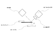
図4に実施例3の構成を示す。図中、上記のものと同一部に関しては同符号を用いる。本実施例のカンチレバー103は、内部に光導波路を有している。この導波路部は、カンチレバー103の外部にある導波路402と結合しており、光源104の光をカンチレバー103内部に導波させる。さらに、カンチレバー103先端の端面にはマイクロレンズ403が密着されており、導波されてきた光を集光させて外部に出力する。 FIG. 4 shows the configuration of the third embodiment. In the figure, the same reference numerals are used for the same parts as those described above. The cantilever 103 of the present embodiment has an optical waveguide inside. This waveguide section is coupled to a waveguide 402 outside the cantilever 103, and guides light from the light source 104 into the cantilever 103. Further, a microlens 403 is in close contact with the end face of the cantilever 103, and the guided light is condensed and output to the outside.
本実施例の偏向素子101の出射面は、増幅された検出光の伝播角度と偏向素子101の端面から出射する検出光の出射角度が等しくなるように、加工されている。そのため、偏向素子101によって伝播角度が増幅された検出光は、増幅された角度を保持したまま、フォトディテクタ102に入射することができる。 The exit surface of the deflection element 101 of this embodiment is processed so that the propagation angle of the amplified detection light and the exit angle of the detection light exiting from the end face of the deflection element 101 are equal. Therefore, the detection light whose propagation angle is amplified by the deflecting element 101 can be incident on the photodetector 102 while maintaining the amplified angle.
ここでも、フォトディテクタ102としては、4分割フォトニックダイオードを用いる。光源104としては、波長660nmのレーザを用いる。勿論、偏向素子101はこのレーザ光の帯域において、屈折率異常(スーパープリズム効果)が起きるように、結晶構造が制御されている。 Again, a quadrant photonic diode is used as the photodetector 102. As the light source 104, a laser having a wavelength of 660 nm is used. Of course, the crystal structure of the deflecting element 101 is controlled so that the refractive index abnormality (super prism effect) occurs in this laser light band.
本実施例では、光源104からの検出光はカンチレバー103先端のマイクロレンズ403から出射して、偏向素子101に入射する。したがって、カンチレバー103の変位に伴ってマイクロレンズ403からの出射方向が変位し、この変位が偏向素子101で増幅されることになる。これらの素子を用いても、サンプル105上をカンチレバー103で走査することにより、カンチレバー103の微小な変位も精度良く簡単な構成で観察することが可能になる。 In this embodiment, the detection light from the light source 104 is emitted from the microlens 403 at the tip of the cantilever 103 and enters the deflection element 101. Therefore, the emission direction from the microlens 403 is displaced with the displacement of the cantilever 103, and this displacement is amplified by the deflection element 101. Even if these elements are used, by scanning the sample 105 with the cantilever 103, a minute displacement of the cantilever 103 can be accurately observed with a simple configuration.
図5に実施例4の構成を示す。図中、上記のものと同一部に関しては同符号を用いる。本実施例のカンチレバー103も、実施例3のものと同じである。本実施例の偏向素子101は、フォトディテクタ102の光検出面と密着している。そのため、偏向素子101によって伝播角度が増幅された検出光は、増幅された角度を保持したまま、フォトディテクタ102に直接入射される。 FIG. 5 shows the configuration of the fourth embodiment. In the figure, the same reference numerals are used for the same parts as those described above. The cantilever 103 of the present embodiment is the same as that of the third embodiment. The deflection element 101 of this embodiment is in close contact with the light detection surface of the photodetector 102. Therefore, the detection light whose propagation angle is amplified by the deflecting element 101 is directly incident on the photodetector 102 while maintaining the amplified angle.
ここでも、フォトディテクタ102としては、4分割フォトニックダイオードを用いる。光源104としては、波長660nmのレーザを用いる。勿論、偏向素子101はこのレーザ光の帯域において、屈折率異常(スーパープリズム効果)が起きるように、結晶構造が制御されている。 Again, a quadrant photonic diode is used as the photodetector 102. As the light source 104, a laser having a wavelength of 660 nm is used. Of course, the crystal structure of the deflecting element 101 is controlled so that the refractive index abnormality (super prism effect) occurs in this laser light band.
これらの素子を用いても、サンプル105上をカンチレバー103で走査することにより、カンチレバー103の微小な変位も精度良く簡単な構成で観察することが可能になる。 Even if these elements are used, by scanning the sample 105 with the cantilever 103, a minute displacement of the cantilever 103 can be accurately observed with a simple configuration.
101 偏向素子
102 フォトディテクタ
103 カンチレバー
103a プローブ
104 光源
105 サンプル
402 導波路
403 レンズ
101 deflection element
102 Photo detector
103 Cantilever
103a probe
104 Light source
105 samples
402 waveguide
403 lens
Claims (7)
前記被測定物から来る検出光が入射する様に配置された屈折率が周期的に変化する屈折率周期構造体と、
該屈折率周期構造体からの検出光の角度変化を計測する光検出手段と、を有し、
前記屈折率周期構造体は、前記検出光が該屈折率周期構造体に入射する角度の変化に比べて、該検出光が該屈折率周期構造体内を伝播する角度の変化が増幅されるように構成され、且つ該屈折率周期構造体を透過して出射した前記検出光が、前記伝播する角度を保持して前記光検出手段に入射するように構成されることを特徴とする変位検出装置。 A displacement detection device that detects displacement of an object to be measured using a change in angle of detection light coming from the object to be measured,
A refractive index periodic structure in which the refractive index is periodically changed so that detection light coming from the object to be measured is incident;
Photodetection means for measuring the angle change of the detection light from the refractive index periodic structure,
The refractive index periodic structure is amplified so that the change in the angle at which the detection light propagates through the refractive index periodic structure is amplified compared to the change in the angle at which the detection light is incident on the refractive index periodic structure. A displacement detection device configured to be configured so that the detection light transmitted through and exiting the refractive index periodic structure is incident on the light detection means while maintaining the propagating angle.
前記検出光が前記入射面の中心に入射されるように構成されていることを特徴とする請求項1に記載の変位検出装置。 The refractive index periodic structure has a propagation angle formed by a propagation direction of light propagating through the refractive index periodic structure with respect to a normal line of an incident surface of the refractive index periodic structure on which the detection light is incident, and the incident The end surface of the refractive index periodic structure from which the detection light exits is spherical so that the exit angle formed by the propagation direction of the detection light exiting from the refractive index periodic structure with respect to the surface normal is equal. Processed,
The displacement detection device according to claim 1, wherein the detection light is configured to be incident on a center of the incident surface.
前記被測定物と前記屈折率周期構造体とは、
前記光導波路を伝播した前記検出光が、前記レンズで集光されて出射し、前記屈折率周期構造体に入射するように配置されることを特徴とする請求項1乃至3のいずれかに記載の変位検出装置。 The object to be measured includes an optical waveguide, and a lens optically coupled to the optical waveguide at a tip of the object to be measured;
The object to be measured and the refractive index periodic structure are:
4. The detection light propagating through the optical waveguide is condensed and emitted by the lens, and disposed so as to enter the refractive index periodic structure. Displacement detector.
測定物と前記プローブとの間に存在する物理量によって撓む前記カンチレバーの撓み量を検出することを特徴とする請求項1乃至4のいずれかに記載の変位検出装置。 The object to be measured is a cantilever, and the cantilever has a probe;
5. The displacement detection device according to claim 1, wherein an amount of bending of the cantilever which is bent by a physical quantity existing between a measurement object and the probe is detected.
前記光源が発生した光を前記光導波路に結合させるための導波路と、を有することを特徴とする請求項4に記載の変位検出装置。 A light source for generating light;
The displacement detection device according to claim 4 , further comprising: a waveguide for coupling light generated by the light source to the optical waveguide.
Priority Applications (1)
| Application Number | Priority Date | Filing Date | Title |
|---|---|---|---|
| JP2003270260A JP4272946B2 (en) | 2003-07-02 | 2003-07-02 | Device for detecting displacement of measured object |
Applications Claiming Priority (1)
| Application Number | Priority Date | Filing Date | Title |
|---|---|---|---|
| JP2003270260A JP4272946B2 (en) | 2003-07-02 | 2003-07-02 | Device for detecting displacement of measured object |
Publications (3)
| Publication Number | Publication Date |
|---|---|
| JP2005024490A JP2005024490A (en) | 2005-01-27 |
| JP2005024490A5 JP2005024490A5 (en) | 2006-08-17 |
| JP4272946B2 true JP4272946B2 (en) | 2009-06-03 |
Family
ID=34190265
Family Applications (1)
| Application Number | Title | Priority Date | Filing Date |
|---|---|---|---|
| JP2003270260A Expired - Fee Related JP4272946B2 (en) | 2003-07-02 | 2003-07-02 | Device for detecting displacement of measured object |
Country Status (1)
| Country | Link |
|---|---|
| JP (1) | JP4272946B2 (en) |
Cited By (1)
| Publication number | Priority date | Publication date | Assignee | Title |
|---|---|---|---|---|
| CN105091771A (en) * | 2015-05-25 | 2015-11-25 | 合肥工业大学 | Apparatus for measuring micro-deformation of connecting rod based on displacement amplification principle |
Families Citing this family (1)
| Publication number | Priority date | Publication date | Assignee | Title |
|---|---|---|---|---|
| US20080259918A1 (en) * | 2007-04-19 | 2008-10-23 | Craig Elliott Walker | Method and apparatus for managing telephone calls |
-
2003
- 2003-07-02 JP JP2003270260A patent/JP4272946B2/en not_active Expired - Fee Related
Cited By (1)
| Publication number | Priority date | Publication date | Assignee | Title |
|---|---|---|---|---|
| CN105091771A (en) * | 2015-05-25 | 2015-11-25 | 合肥工业大学 | Apparatus for measuring micro-deformation of connecting rod based on displacement amplification principle |
Also Published As
| Publication number | Publication date |
|---|---|
| JP2005024490A (en) | 2005-01-27 |
Similar Documents
| Publication | Publication Date | Title |
|---|---|---|
| JP4489804B2 (en) | Homodyne laser interferometer probe and displacement measurement system using the same | |
| JPH0921698A (en) | Optical sensor | |
| US6239426B1 (en) | Scanning probe and scanning probe microscope | |
| KR100486937B1 (en) | A concave ended interferometric Optical Fiber Sensor for Displacement measurement of Cantilever Probe of Atomic Force Microscope | |
| US7586084B2 (en) | Optical fiber probe, optical detection device, and optical detection method | |
| US6642517B1 (en) | Method and apparatus for atomic force microscopy | |
| Bruland et al. | Thermal tuning of a fiber-optic interferometer for maximum sensitivity | |
| JP4009197B2 (en) | Scanning near-field optical microscope | |
| EP0415838B1 (en) | Microscopic method and "near-field" reflection microscope | |
| JPH1144693A (en) | Method and apparatus for measurement of position of probe chip in near-field optical microscope and control device therefor | |
| JP4553240B2 (en) | Photodetection device and photodetection method | |
| EP0652414B1 (en) | Scanning near-field optic/atomic force microscope | |
| JP4272946B2 (en) | Device for detecting displacement of measured object | |
| US7319527B2 (en) | Sensor with cantilever and optical resonator | |
| WO2005003737A1 (en) | Photo-detection device and method | |
| Tiribilli et al. | Fibre‐top atomic force microscope probe with optical near‐field detection capabilities | |
| US20070012873A1 (en) | Scanning-type probe microscope | |
| KR100343813B1 (en) | Apparatus and method for measuring the refractive index profile of a optical fiber or waveguide surface | |
| JP3450460B2 (en) | Scanning probe microscope | |
| JP2007322159A (en) | Optical fiber probe, photodetector, and photodetection method | |
| JP2004257775A (en) | Method and device for measuring indentation depth of spherical indenter | |
| JPH1194859A (en) | Scanning near-field optical microscope utilizing optical resonator | |
| JP3242787B2 (en) | Photon scanning tunneling microscope | |
| JPH04131710A (en) | Scanning type probe microscope | |
| JPH0483137A (en) | Minute force detector |
Legal Events
| Date | Code | Title | Description |
|---|---|---|---|
| A521 | Written amendment |
Free format text: JAPANESE INTERMEDIATE CODE: A523 Effective date: 20060703 |
|
| A621 | Written request for application examination |
Free format text: JAPANESE INTERMEDIATE CODE: A621 Effective date: 20060703 |
|
| A977 | Report on retrieval |
Free format text: JAPANESE INTERMEDIATE CODE: A971007 Effective date: 20080605 |
|
| A131 | Notification of reasons for refusal |
Free format text: JAPANESE INTERMEDIATE CODE: A131 Effective date: 20080609 |
|
| A521 | Written amendment |
Free format text: JAPANESE INTERMEDIATE CODE: A523 Effective date: 20080728 |
|
| A131 | Notification of reasons for refusal |
Free format text: JAPANESE INTERMEDIATE CODE: A131 Effective date: 20081203 |
|
| A521 | Written amendment |
Free format text: JAPANESE INTERMEDIATE CODE: A523 Effective date: 20081212 |
|
| TRDD | Decision of grant or rejection written | ||
| A01 | Written decision to grant a patent or to grant a registration (utility model) |
Free format text: JAPANESE INTERMEDIATE CODE: A01 Effective date: 20090219 |
|
| A01 | Written decision to grant a patent or to grant a registration (utility model) |
Free format text: JAPANESE INTERMEDIATE CODE: A01 |
|
| A61 | First payment of annual fees (during grant procedure) |
Free format text: JAPANESE INTERMEDIATE CODE: A61 Effective date: 20090302 |
|
| FPAY | Renewal fee payment (event date is renewal date of database) |
Free format text: PAYMENT UNTIL: 20120306 Year of fee payment: 3 |
|
| R150 | Certificate of patent or registration of utility model |
Free format text: JAPANESE INTERMEDIATE CODE: R150 |
|
| FPAY | Renewal fee payment (event date is renewal date of database) |
Free format text: PAYMENT UNTIL: 20130306 Year of fee payment: 4 |
|
| FPAY | Renewal fee payment (event date is renewal date of database) |
Free format text: PAYMENT UNTIL: 20140306 Year of fee payment: 5 |
|
| LAPS | Cancellation because of no payment of annual fees |