JP4272674B2 - Footwear having a bottom structure incorporating a branched fluid-filled chamber - Google Patents
Footwear having a bottom structure incorporating a branched fluid-filled chamber Download PDFInfo
- Publication number
- JP4272674B2 JP4272674B2 JP2006520174A JP2006520174A JP4272674B2 JP 4272674 B2 JP4272674 B2 JP 4272674B2 JP 2006520174 A JP2006520174 A JP 2006520174A JP 2006520174 A JP2006520174 A JP 2006520174A JP 4272674 B2 JP4272674 B2 JP 4272674B2
- Authority
- JP
- Japan
- Prior art keywords
- chamber
- parison
- mold
- parting line
- forming
- Prior art date
- Legal status (The legal status is an assumption and is not a legal conclusion. Google has not performed a legal analysis and makes no representation as to the accuracy of the status listed.)
- Active
Links
- 239000012530 fluid Substances 0.000 title claims abstract description 53
- 238000000034 method Methods 0.000 claims abstract description 55
- 238000004519 manufacturing process Methods 0.000 claims abstract description 15
- 238000005452 bending Methods 0.000 claims description 16
- 238000000465 moulding Methods 0.000 claims description 5
- 238000004026 adhesive bonding Methods 0.000 claims 6
- 238000004891 communication Methods 0.000 abstract description 3
- 239000000463 material Substances 0.000 description 34
- 239000006261 foam material Substances 0.000 description 23
- 230000006835 compression Effects 0.000 description 20
- 238000007906 compression Methods 0.000 description 20
- 210000002683 foot Anatomy 0.000 description 20
- 239000006260 foam Substances 0.000 description 14
- 230000004044 response Effects 0.000 description 14
- 238000000071 blow moulding Methods 0.000 description 13
- 239000002861 polymer material Substances 0.000 description 12
- 238000006243 chemical reaction Methods 0.000 description 10
- 230000000694 effects Effects 0.000 description 10
- 239000000835 fiber Substances 0.000 description 9
- 239000002184 metal Substances 0.000 description 7
- 229920002635 polyurethane Polymers 0.000 description 7
- 239000004814 polyurethane Substances 0.000 description 7
- 229920002803 thermoplastic polyurethane Polymers 0.000 description 7
- 230000015572 biosynthetic process Effects 0.000 description 6
- 230000002093 peripheral effect Effects 0.000 description 5
- 230000008569 process Effects 0.000 description 5
- 239000004433 Thermoplastic polyurethane Substances 0.000 description 4
- 230000004888 barrier function Effects 0.000 description 4
- 230000008901 benefit Effects 0.000 description 4
- 239000013536 elastomeric material Substances 0.000 description 4
- 229920000642 polymer Polymers 0.000 description 4
- 238000007493 shaping process Methods 0.000 description 4
- 230000007704 transition Effects 0.000 description 4
- IJGRMHOSHXDMSA-UHFFFAOYSA-N Atomic nitrogen Chemical compound N#N IJGRMHOSHXDMSA-UHFFFAOYSA-N 0.000 description 3
- 230000000386 athletic effect Effects 0.000 description 3
- BFMKFCLXZSUVPI-UHFFFAOYSA-N ethyl but-3-enoate Chemical compound CCOC(=O)CC=C BFMKFCLXZSUVPI-UHFFFAOYSA-N 0.000 description 3
- 239000007789 gas Substances 0.000 description 3
- 229920000728 polyester Polymers 0.000 description 3
- 238000003856 thermoforming Methods 0.000 description 3
- 229920002725 thermoplastic elastomer Polymers 0.000 description 3
- 239000012815 thermoplastic material Substances 0.000 description 3
- RTZKZFJDLAIYFH-UHFFFAOYSA-N Diethyl ether Chemical compound CCOCC RTZKZFJDLAIYFH-UHFFFAOYSA-N 0.000 description 2
- 229920000219 Ethylene vinyl alcohol Polymers 0.000 description 2
- 230000009471 action Effects 0.000 description 2
- 238000013459 approach Methods 0.000 description 2
- 230000008859 change Effects 0.000 description 2
- 230000007423 decrease Effects 0.000 description 2
- 150000002148 esters Chemical class 0.000 description 2
- 239000004744 fabric Substances 0.000 description 2
- 230000006870 function Effects 0.000 description 2
- 239000010985 leather Substances 0.000 description 2
- 239000007788 liquid Substances 0.000 description 2
- 239000012528 membrane Substances 0.000 description 2
- 229920000570 polyether Polymers 0.000 description 2
- 229920001169 thermoplastic Polymers 0.000 description 2
- 239000004416 thermosoftening plastic Substances 0.000 description 2
- CRWSWMKELFKJMC-UHFFFAOYSA-N CC.F.F.F.F.F.F Chemical compound CC.F.F.F.F.F.F CRWSWMKELFKJMC-UHFFFAOYSA-N 0.000 description 1
- 229920006347 Elastollan Polymers 0.000 description 1
- VGGSQFUCUMXWEO-UHFFFAOYSA-N Ethene Chemical compound C=C VGGSQFUCUMXWEO-UHFFFAOYSA-N 0.000 description 1
- 239000005977 Ethylene Substances 0.000 description 1
- RYECOJGRJDOGPP-UHFFFAOYSA-N Ethylurea Chemical compound CCNC(N)=O RYECOJGRJDOGPP-UHFFFAOYSA-N 0.000 description 1
- 239000004721 Polyphenylene oxide Substances 0.000 description 1
- 229910018503 SF6 Inorganic materials 0.000 description 1
- 238000010521 absorption reaction Methods 0.000 description 1
- 239000000853 adhesive Substances 0.000 description 1
- 230000001070 adhesive effect Effects 0.000 description 1
- 238000005266 casting Methods 0.000 description 1
- 229920001577 copolymer Polymers 0.000 description 1
- 230000008878 coupling Effects 0.000 description 1
- 238000010168 coupling process Methods 0.000 description 1
- 238000005859 coupling reaction Methods 0.000 description 1
- 239000002178 crystalline material Substances 0.000 description 1
- 230000003247 decreasing effect Effects 0.000 description 1
- 238000013461 design Methods 0.000 description 1
- 238000009792 diffusion process Methods 0.000 description 1
- 229910001873 dinitrogen Inorganic materials 0.000 description 1
- 229920001971 elastomer Polymers 0.000 description 1
- 239000000806 elastomer Substances 0.000 description 1
- 238000001125 extrusion Methods 0.000 description 1
- 238000007373 indentation Methods 0.000 description 1
- 238000009940 knitting Methods 0.000 description 1
- 238000010030 laminating Methods 0.000 description 1
- 230000007246 mechanism Effects 0.000 description 1
- 238000012986 modification Methods 0.000 description 1
- 230000004048 modification Effects 0.000 description 1
- 229910052757 nitrogen Inorganic materials 0.000 description 1
- 229920001610 polycaprolactone Polymers 0.000 description 1
- 229920000515 polycarbonate Polymers 0.000 description 1
- 239000004417 polycarbonate Substances 0.000 description 1
- 229920005906 polyester polyol Polymers 0.000 description 1
- 229920006264 polyurethane film Polymers 0.000 description 1
- 238000003825 pressing Methods 0.000 description 1
- 230000009467 reduction Effects 0.000 description 1
- 238000001175 rotational moulding Methods 0.000 description 1
- 238000007789 sealing Methods 0.000 description 1
- 238000009958 sewing Methods 0.000 description 1
- 239000000126 substance Substances 0.000 description 1
- SFZCNBIFKDRMGX-UHFFFAOYSA-N sulfur hexafluoride Chemical compound FS(F)(F)(F)(F)F SFZCNBIFKDRMGX-UHFFFAOYSA-N 0.000 description 1
- 229960000909 sulfur hexafluoride Drugs 0.000 description 1
- 210000003813 thumb Anatomy 0.000 description 1
- 210000003371 toe Anatomy 0.000 description 1
- 238000012549 training Methods 0.000 description 1
- 238000009966 trimming Methods 0.000 description 1
Images


Classifications
-
- B—PERFORMING OPERATIONS; TRANSPORTING
- B29—WORKING OF PLASTICS; WORKING OF SUBSTANCES IN A PLASTIC STATE IN GENERAL
- B29D—PRODUCING PARTICULAR ARTICLES FROM PLASTICS OR FROM SUBSTANCES IN A PLASTIC STATE
- B29D35/00—Producing footwear
- B29D35/12—Producing parts thereof, e.g. soles, heels, uppers, by a moulding technique
- B29D35/122—Soles
-
- A—HUMAN NECESSITIES
- A43—FOOTWEAR
- A43B—CHARACTERISTIC FEATURES OF FOOTWEAR; PARTS OF FOOTWEAR
- A43B13/00—Soles; Sole-and-heel integral units
- A43B13/14—Soles; Sole-and-heel integral units characterised by the constructive form
- A43B13/18—Resilient soles
- A43B13/20—Pneumatic soles filled with a compressible fluid, e.g. air, gas
-
- A—HUMAN NECESSITIES
- A43—FOOTWEAR
- A43B—CHARACTERISTIC FEATURES OF FOOTWEAR; PARTS OF FOOTWEAR
- A43B17/00—Insoles for insertion, e.g. footbeds or inlays, for attachment to the shoe after the upper has been joined
- A43B17/02—Insoles for insertion, e.g. footbeds or inlays, for attachment to the shoe after the upper has been joined wedge-like or resilient
- A43B17/03—Insoles for insertion, e.g. footbeds or inlays, for attachment to the shoe after the upper has been joined wedge-like or resilient filled with a gas, e.g. air
-
- B—PERFORMING OPERATIONS; TRANSPORTING
- B29—WORKING OF PLASTICS; WORKING OF SUBSTANCES IN A PLASTIC STATE IN GENERAL
- B29C—SHAPING OR JOINING OF PLASTICS; SHAPING OF MATERIAL IN A PLASTIC STATE, NOT OTHERWISE PROVIDED FOR; AFTER-TREATMENT OF THE SHAPED PRODUCTS, e.g. REPAIRING
- B29C49/00—Blow-moulding, i.e. blowing a preform or parison to a desired shape within a mould; Apparatus therefor
- B29C49/02—Combined blow-moulding and manufacture of the preform or the parison
- B29C49/06905—Using combined techniques for making the preform
- B29C49/0691—Using combined techniques for making the preform using sheet like material, e.g. sheet blow-moulding from joined sheets
-
- B—PERFORMING OPERATIONS; TRANSPORTING
- B29—WORKING OF PLASTICS; WORKING OF SUBSTANCES IN A PLASTIC STATE IN GENERAL
- B29C—SHAPING OR JOINING OF PLASTICS; SHAPING OF MATERIAL IN A PLASTIC STATE, NOT OTHERWISE PROVIDED FOR; AFTER-TREATMENT OF THE SHAPED PRODUCTS, e.g. REPAIRING
- B29C51/00—Shaping by thermoforming, i.e. shaping sheets or sheet like preforms after heating, e.g. shaping sheets in matched moulds or by deep-drawing; Apparatus therefor
- B29C51/02—Combined thermoforming and manufacture of the preform
-
- B—PERFORMING OPERATIONS; TRANSPORTING
- B29—WORKING OF PLASTICS; WORKING OF SUBSTANCES IN A PLASTIC STATE IN GENERAL
- B29L—INDEXING SCHEME ASSOCIATED WITH SUBCLASS B29C, RELATING TO PARTICULAR ARTICLES
- B29L2031/00—Other particular articles
- B29L2031/48—Wearing apparel
- B29L2031/50—Footwear, e.g. shoes or parts thereof
- B29L2031/504—Soles
-
- Y—GENERAL TAGGING OF NEW TECHNOLOGICAL DEVELOPMENTS; GENERAL TAGGING OF CROSS-SECTIONAL TECHNOLOGIES SPANNING OVER SEVERAL SECTIONS OF THE IPC; TECHNICAL SUBJECTS COVERED BY FORMER USPC CROSS-REFERENCE ART COLLECTIONS [XRACs] AND DIGESTS
- Y10—TECHNICAL SUBJECTS COVERED BY FORMER USPC
- Y10T—TECHNICAL SUBJECTS COVERED BY FORMER US CLASSIFICATION
- Y10T156/00—Adhesive bonding and miscellaneous chemical manufacture
- Y10T156/10—Methods of surface bonding and/or assembly therefor
- Y10T156/1002—Methods of surface bonding and/or assembly therefor with permanent bending or reshaping or surface deformation of self sustaining lamina
Abstract
Description
本発明は履物(靴)に関する。さらに詳しくは、本発明は履物の用途に適した流体を充填したチャンバーであって、分岐構造(突出部を有する構造)を有するチャンバーに関する。 The present invention relates to footwear (shoes). More specifically, the present invention relates to a chamber filled with a fluid suitable for footwear use and having a branch structure (structure having a protrusion).
通常の靴は2つの主な要素、アッパーと底部(ソール)とを有する。運動靴(運動用の履物)に関しては、例えばアッパーは一般に織物、発泡体およびレザーのような複数の材料層を含んでおり、それらを縫い合わせ、または接着剤で貼り合わせて、足を確実にかつ快適に収容する空間を靴の内部に形成している。底部構造はインソール、ミッドソール、およびアウトソールを含む層状構造を有する。インソールは足に隣接して位置する薄いクッション部材で、靴の快適性を向上させる。ミッドソールは靴底構造の中間層をなし、通常ポリウレタンまたはエチルビニルアセテートなどのフォーム(発泡)材料で形成される。アウトソールはミッドソールの下面に固定され、地面を捕捉するための耐久性がある耐摩耗性の表面を構成している。 A typical shoe has two main elements: an upper and a bottom (sole). With regard to athletic shoes (athletic footwear), for example, the upper typically includes multiple layers of material such as fabric, foam and leather, which are stitched together or glued together to ensure the foot and A comfortable space is formed inside the shoe. The bottom structure has a layered structure including an insole, a midsole, and an outsole. The insole is a thin cushion member located adjacent to the foot and improves the comfort of the shoe. The midsole forms an intermediate layer of a sole structure and is usually formed of a foam (foam) material such as polyurethane or ethyl vinyl acetate. The outsole is secured to the lower surface of the midsole and constitutes a durable, wear-resistant surface for capturing the ground.
通常の発泡材料で形成されたミッドソールは、負荷を受けると柔軟性を持って収縮し、例えば歩行やランニングに伴う力を減衰させエネルギーを吸収する。ミッドソールの柔軟性のある収縮は、部分的には、内部の体積を規定する発泡体構造の中のセルが実質的に気体で置き換えられていることによる。すなわち、発泡材料は空気を密封した複数のポケットを含む。しかし収縮を繰り返すと、セル構造は永久的に壊れ始め、その結果発泡体の伸縮性が低下する。そのため、力を減衰させエネルギーを吸収するミッドソールの全体としての性能は、ミッドソールの耐用期間を通じて低下していく。 A midsole formed of a normal foam material contracts with flexibility when subjected to a load, for example, attenuates a force accompanying walking or running and absorbs energy. The flexible shrinkage of the midsole is due, in part, to the fact that the cells in the foam structure that define the interior volume have been substantially replaced with gas. That is, the foam material includes a plurality of pockets sealed with air. However, when the shrinkage is repeated, the cell structure starts to be permanently broken, and as a result, the stretchability of the foam is lowered. As a result, the overall performance of the midsole that attenuates force and absorbs energy decreases over the life of the midsole.
通常の発泡体におけるセル構造の壊れの影響を低減する1つの方法は、Rudyに特許を付与されてここに引用により組み込まれた下記特許文献1に開示されているように、流体充填チャンバーとして構成された構造を利用することである。前記流体充填チャンバーは、靴の全長にわたって長手方向に延びている複数の筒状部材を規定するエラストマー材料で形成された外部包囲部材を含む、袋状の構造を有する。前記各筒状部材は互いに流体的に連通状態にあり、共に靴の幅を横切って延びている。Rudyに特許を付与され、同様に引用により本明細書に組み込まれた下記特許文献2は、発泡体の中に封入された同様の流体充填チャンバーを開示しており、この場合、流体充填チャンバーと封止発泡体とを組み合わせたものがミッドソールとして機能する。 One way to reduce the effects of cell structure breakage in a normal foam is to configure it as a fluid-filled chamber, as disclosed in U.S. Pat. Is to make use of the structured. The fluid-filled chamber has a bag-like structure including an outer surrounding member formed of an elastomeric material that defines a plurality of cylindrical members extending longitudinally over the entire length of the shoe. The tubular members are in fluid communication with each other and both extend across the width of the shoe. The following US Pat. No. 6,057,097, which is patented to Rudy and also incorporated herein by reference, discloses a similar fluid-filled chamber enclosed in a foam, in which case a fluid-filled chamber and A combination with the sealing foam functions as a midsole.
Parker他に特許を付与されて引用により本明細書に組み込まれた下記特許文献3は、発泡体に封入された流体充填チャンバーであって、前記チャンバーの両側に沿って発泡体の中に開口部が形成されたものを開示している。ミッドソールが圧縮されると、チャンバーは前記開口部内に向かって膨張する。従ってミッドソールが圧縮されている間、開口部は剛性を低下させながら、靴の全重量を低下させる。更に発泡体中で開口部を適切に配置することにより、靴の特定の部位において全体の衝撃応答特性を調整することが出来る。 The following US Pat. No. 6,057,009, patented by Parker et al. And incorporated herein by reference, is a fluid-filled chamber enclosed in a foam, with openings in the foam along both sides of the chamber. Is disclosed. As the midsole is compressed, the chamber expands into the opening. Thus, while the midsole is compressed, the opening reduces the overall weight of the shoe while reducing stiffness. Further, by appropriately disposing the opening in the foam, the overall impact response characteristics can be adjusted at a specific part of the shoe.
上記の流体充填チャンバーは2枚の膜を使った方法で製造することができるが、これはエラストマーフィルムでできた独立した2つの層をチャンバーの全体形状に成形するものである。次に各層を外周に沿って接着してチャンバーの上面、下面および側壁を形成し、そして各層は内部の所定の位置で互いに接着されてチャンバーに所望の形状を与える。すなわち、各層の内側の部分を結合して、所望の位置に所定の形状および寸法のチャンバーを形成する。続いて、流体圧力源に接続されたノズルまたは針をチャンバー内に形成された充填口に差し込んで、各チャンバー内に大気圧よりも高い圧力を与える。チャンバーに圧力を与えた後でノズルを外し、例えば接着により充填口を封止する。 The fluid-filled chamber can be manufactured by a method using two membranes, which are formed by forming two independent layers made of an elastomer film into the overall shape of the chamber. The layers are then bonded along the outer periphery to form the top, bottom and sidewalls of the chamber, and the layers are bonded together at predetermined locations within the chamber to give the chamber the desired shape. That is, the inner portions of the layers are joined to form a chamber having a predetermined shape and size at a desired position. Subsequently, a nozzle or a needle connected to a fluid pressure source is inserted into a filling port formed in the chamber, and a pressure higher than the atmospheric pressure is applied in each chamber. After the pressure is applied to the chamber, the nozzle is removed, and the filling port is sealed by, for example, adhesion.
上記のタイプの流体充填チャンバーを製造するための別の製造方法として、ブロー成型法があり、これは所望の全体形状およびチャンバー形状を有する金型内に液状のエラストマー材料を入れる。金型は1箇所に開口部を有し、それを通して圧縮空気が供給される。圧縮空気は金型の内部表面に液状のエラストマー材料を押し付け、この材料を金型内で硬化させ、それにより所望の形状を有するチャンバーを形成する。 Another manufacturing method for manufacturing a fluid filled chamber of the type described above is a blow molding method, which places a liquid elastomeric material in a mold having the desired overall shape and chamber shape. The mold has an opening at one location, through which compressed air is supplied. The compressed air presses the liquid elastomeric material against the inner surface of the mold and cures the material in the mold, thereby forming a chamber having the desired shape.
靴のミッドソール内で利用される別のタイプのチャンバーが、共にRudyに特許を付与されて引用により本明細書に組み込まれた下記特許文献4および下記特許文献5に開示されている。これらチャンバーは、二重壁構造の繊維コアの上に接着固定された、気密に封止された外部バリア層を含む。二重壁構造の繊維コアは、通常互いに所定の距離を開けて配設された上部および下部の外部繊維層を有し、二重ニードルバー(針ざお)方式のラッシェル編み工程で製造することが出来る。多くの個別繊維を用いたマルチフィラメント(多繊維)糸の形態を有することのできる接続用糸が、繊維層同士の対向する各面の間の内部に延びており、繊維層に固定される。接続用糸の個別の繊維は、バリア層が所望の距離まで外に向かって移動するのを規制する引っ張り規制部材を構成する。 Another type of chamber utilized within a shoe midsole is disclosed in U.S. Pat. Nos. 5,057,049 and 5,056,097, both of which are patented to Rudy and incorporated herein by reference. These chambers include a hermetically sealed outer barrier layer that is adhesively bonded onto a double-walled fiber core. A fiber core having a double wall structure usually has upper and lower outer fiber layers arranged at a predetermined distance from each other, and can be manufactured by a Raschel knitting process of a double needle bar type. I can do it. A connecting yarn that can have the form of a multifilament (multifilament) yarn using a number of individual fibers extends to the inside between the opposing surfaces of the fiber layers and is fixed to the fiber layer. The individual fibers of the connecting yarn constitute a tension restricting member that restricts the barrier layer from moving outward to a desired distance.
どちらもGoodwin他に特許を付与されて両方とも引用により本明細書に組み込まれた下記特許文献6および下記特許文献7も二重壁構造の繊維コアを組み込んだチャンバーを開示しているが、チャンバーの上面と下面との中間の位置に周辺の継ぎ目は無い。その代わりに、継ぎ目はチャンバーの上面に隣接して配置されている。この設計の利点としては、側壁の曲がりが最大になる部分から継ぎ目を外すことと、接続用糸を含むチャンバー内部が見やすくなることとがある。このタイプのチャンバーの製作に採用される工程は、下面と側壁とを含む外殻を金型で形成することが含まれる。二重壁構造の繊維コアは被覆層の上に配置され、外郭は被覆層とをコアとを覆うように配置される。外郭、被覆層およびコアを組み合わせたものは積層ステーションに移送され、ここで高周波エネルギーでコアの両側面を外殻と被覆層とに接着し、また外殻の外周を被覆層に接着する。次に流体を注入してチャンバーに圧力を加え、接続用糸に張力を加える。
The following patent document 6 and the following
チャンバーを熱成形する工程が、Skaja他に特許を付与され引用により本明細書に組み込まれた下記特許文献8に開示されているが、これは一対の柔軟な熱可塑性樹脂層を熱し、そして各層を真空吸引により金型内に引き込むことで一対の金型に押し付ける。次に各層を互いに押し付けてチャンバーを形成する。
上で述べたチャンバーの外側層を形成する材料としては、熱可塑性エラストマーのような、チャンバー内の流体が実質的に浸透できないポリマーを使用できる。より具体的には、1つの適切な材料として、Mitchelに特許を付与され引用により本明細書に組み込まれた下記特許文献9および下記特許文献10に開示されているように、熱可塑性ポリウレタンとエチレンビニルアルコール共重合体との各層を交互に積層したフィルムがある。この材料の中央の層をエチレンビニルアルコール共重合体で形成した変形としては、中央層に隣接する2層が熱可塑性ポリウレタンで形成され、外側層が熱可塑性ポリウレタンおよびエチレンビニルアルコール共重合体の粉砕再生材料で形成されるものも利用できる。別の適切な材料としては、Bonk他に認可され両方とも引用により本明細書に組み込まれた下記特許文献11および下記特許文献12に開示されているように、ガスバリア材料の層とエラストマー材料との層を交互に重ねたものを含む柔軟なマイクロレイヤー膜がある。その他の適切な熱可塑性エラストマー材料またはフィルムとしては、ポリウレタン、ポリエステル、ポリエステルポリウレタン、ポリエーテルポリウレタン、鋳造または押出しなどにより成形されたエステル系ポリウレタンフィルムがある。その他の適切な材料が、上で引用したRudyの下記特許文献1および下記特許文献2に開示されている。更にDow Chemical社の製品であるPELLETHANE、BASF社の製品であるELASTOLLAN、B.F. Goodrich社の製品であるESTANEなど、数多くの熱可塑性ウレタン系材料を使用できるが、これらはすべてエステルまたはエーテル系の材料である。更に別の熱可塑性ウレタンでポリエステル、ポリエーテル、ポリカプロラクトンおよびポリカーボネートマクロゲルをベースとするものを使用でき、また様々な窒素遮蔽材料を使用することもできる。更なる適切な材料には、Rudyに特許を付与されて引用により本明細書に組み込まれた下記特許文献13および下記特許文献14に開示されているように、結晶性材料を含む熱可塑性フィルムが含まれ、またBonk他に特許を付与されて引用により本明細書に組み込まれた下記特許文献15、下記特許文献16および下記特許文献17に開示されているようにポリエステルポリオールを含むポリウレタンがある。
The process of thermoforming the chamber is disclosed in U.S. Pat. No. 6,056,097, patented to Skaja et al. And incorporated herein by reference, which heats a pair of flexible thermoplastic layers and each layer Is pressed into a pair of molds by being drawn into the mold by vacuum suction. The layers are then pressed together to form a chamber.
The material forming the outer layer of the chamber described above can be a polymer that is substantially impermeable to fluid in the chamber, such as a thermoplastic elastomer. More specifically, as one suitable material, thermoplastic polyurethane and ethylene, as disclosed in U.S. Pat. There is a film in which each layer with a vinyl alcohol copolymer is alternately laminated. As a deformation of the central layer of this material formed of ethylene vinyl alcohol copolymer, two layers adjacent to the central layer are formed of thermoplastic polyurethane, and the outer layer is pulverized of thermoplastic polyurethane and ethylene vinyl alcohol copolymer. Those made of recycled materials can also be used. Another suitable material includes a layer of gas barrier material and an elastomeric material, as disclosed in US Pat. There are flexible microlayer membranes, including alternating layers. Other suitable thermoplastic elastomer materials or films include polyurethane, polyester, polyester polyurethane, polyether polyurethane, ester polyurethane films formed by casting or extrusion, and the like. Other suitable materials are disclosed by Rudy in the following US Pat. In addition, many thermoplastic urethane materials can be used, such as PELLETHANE from Dow Chemical, ELASTOLLAN from BASF, and ESTANE from BF Goodrich, all of which are ester or ether materials. is there. Further thermoplastic urethanes based on polyesters, polyethers, polycaprolactones and polycarbonate macrogels can be used, and various nitrogen shielding materials can be used. Further suitable materials include thermoplastic films comprising crystalline materials as disclosed in U.S. Pat. Nos. 5,099,036 and 5,098,009, patented to Rudy and incorporated herein by reference. There are polyurethanes containing polyester polyols as disclosed in US Pat. Nos. 5,776, 797 and 5,836, incorporated herein by reference and incorporated by reference into Bonk et al.
チャンバー内に収容される流体は、Rudyに特許を付与された下記特許文献18に開示された気体のいずれか、例えば六フッ化エタンや六フッ化硫黄を含んでもよい。更に、圧力を加えた窒素ガスまたは空気を封入したチャンバーもある。
圧縮が進行すると剛性が高くなるチャンバー、それを含む履物の底構造、およびその履物の底構造を含む履物を提供する。 Provided are a chamber that becomes more rigid as compression progresses, a footwear bottom structure including the chamber, and a footwear including the footwear bottom structure.
本発明は、第一の表面とそれに対向する第二の表面と、前記第一の表面および第二の表面のそれぞれの縁の間で延びている側壁とを含む履物製品(靴)のためのチャンバーに関する。前記第一の表面の内側部分を前記第二の表面の内側部分に固定する内部の結合が存在しないような態様で、前記側壁は第一の表面および前記第二の表面と結合されている。前記チャンバー内には大気圧と大気圧+5psiとの間の圧力で流体が封入されている。更に、チャンバーの中央部分から外側に向かって複数の分岐部が延びている。前記分岐部は、第一の表面、第二の表面および側壁によって区画され、また前記分岐部は前記中央部分と流体的に連通している。 The present invention is for an article of footwear (shoes) comprising a first surface, a second surface opposite thereto, and sidewalls extending between the respective edges of the first surface and the second surface. Relating to the chamber. The sidewalls are bonded to the first surface and the second surface in such a manner that there is no internal bond that secures the inner portion of the first surface to the inner portion of the second surface. A fluid is sealed in the chamber at a pressure between atmospheric pressure and atmospheric pressure + 5 psi. Further, a plurality of branch portions extend outward from the central portion of the chamber. The bifurcation is defined by a first surface, a second surface and a sidewall, and the bifurcation is in fluid communication with the central portion.
前記第一の表面および第二の表面は平坦な形状を有することができる。あるいは、いずれかの表面を曲面とすることもできる。更に、各分岐部間に設けられた側壁の部分は傾斜していてもよく、また各分岐部の先端に隣接する側壁の部分は、実質的に鉛直の傾斜を有することができる。
各分岐部は中央部分から外側に向かって放射状に延びるような形状とすることができる。すなわち、各分岐部は、中央部分の外周から外側に向かって様々な方向に延びることができる。本発明の範囲内において、分岐部の数は大幅に異なっていてもよい。各分岐部は隣接する分岐部の間に位置する空間を規定する。靴の中に組み込まれた場合、チャンバーは少なくとも部分的には発泡ポリマー材料の内部に取り囲まれる。そのため、発泡ポリマーは各分岐部の間に延びて柱状部を形成する。一般に、柱状部の表面は側壁に接触し、隣接する分岐部の間に位置する空間の形状を有する。そのため、柱状部は側壁の傾斜に対応する傾斜した形状を有する。
The first surface and the second surface may have a flat shape. Alternatively, either surface can be a curved surface. Further, the portion of the side wall provided between the branch portions may be inclined, and the portion of the side wall adjacent to the tip of each branch portion may have a substantially vertical inclination.
Each branch part can be shaped to extend radially outward from the central part. That is, each branch part can extend in various directions from the outer periphery of the central portion toward the outside. Within the scope of the present invention, the number of branches may vary greatly. Each branch defines a space located between adjacent branches. When incorporated into a shoe, the chamber is at least partially enclosed within the foamed polymeric material. Therefore, the foamed polymer extends between the branch portions to form a columnar portion. In general, the surface of the columnar part contacts the side wall and has a shape of a space located between adjacent branch parts. Therefore, the columnar part has an inclined shape corresponding to the inclination of the side wall.
チャンバーを形成する材料は一般に熱可塑性エラストマーのようなポリマーであり、それにより袋状部材の構造を構成する。または、履物のミッドソール内の空洞としてチャンバーを形成してもよい。チャンバー内で複数の流体を使用することもできるが、一般に空気が本発明に適した特性を与える。
本発明はまた、履物のための流体充填チャンバーを製造する方法に関する。この方法は、金型の第一の部分および対応する第二の部分の間にパリソンを配置することを含む。次に、第一の部分と第二の部分とを互いに向けて移動して金型の外形にパリソンを曲げる。金型の外形は金型内部の空洞から離れて位置しており、前記空洞はチャンバーの形状を有する。次に、パリソンの対向する両側が、空洞内のチャンバーを形成するように形作られ、そしてパリソンの対向する両側が互いに接着される。
The material forming the chamber is typically a polymer such as a thermoplastic elastomer, thereby constituting the structure of the bag-like member. Alternatively, the chamber may be formed as a cavity in the midsole of the footwear. Although multiple fluids can be used in the chamber, air generally provides properties suitable for the present invention.
The invention also relates to a method of manufacturing a fluid-filled chamber for footwear. The method includes placing a parison between a first portion of the mold and a corresponding second portion. Next, the first portion and the second portion are moved toward each other to bend the parison into the outer shape of the mold. The outer shape of the mold is located away from the cavity inside the mold, and the cavity has the shape of a chamber. Next, the opposing sides of the parison are shaped to form a chamber within the cavity, and the opposing sides of the parison are glued together.
本発明を特徴付ける利点および新規な特徴は、添付の特許請求の範囲において具体的に指摘される。しかしこの利点および新規な特徴をより良く理解できるよう、本発明の様々な実施形態と概念とを説明する下記の記述および添付図面を参照する。
上記の発明の開示および下記の発明を実施するための最良の形態は、添付図面と共に読むことでよりよく理解されるであろう。
The advantages and novel features which characterize the invention are pointed out with particularity in the appended claims. However, in order to better understand this advantage and novel features, reference is made to the following description and accompanying drawings that illustrate various embodiments and concepts of the invention.
The above disclosure and the best mode for carrying out the invention will be better understood when read in conjunction with the appended drawings.
緒言
下記の記述および添付図面は、本発明に係る流体を充填したチャンバーを組み込んだ運動用の履物(靴)を開示する。前記靴、またより具体的には流体充填チャンバーに関わる概念を、ランニングに適した形状を有する靴に関して開示する。本発明はランニング用に設計された靴のみに限定されるものではなく、例えばバスケットボールシューズ、クロストレーニング用シューズ、ウォーキングシューズ、テニスシューズ、サッカーシューズ、およびハイキング用靴など、広範囲の運動靴に適用することが出来る。更に本発明は、ドレス用の靴、ローファー、サンダルおよび作業靴を含む、運動用でない靴にも適用することが出来る。従って当業者であれば、ここに開示される概念が下記の記述および添付図面によって説明される特定のスタイルに加えて、広範囲の様々なスタイルの靴に応用できることが理解されるであろう。
第一のチャンバー
図1に示す靴10はアッパー(上部)20と靴底構造30とを含む。アッパー20は概略従来の形状を有し、織物、発泡体およびレザーのような複数の要素を縫い合わせ、または接着剤で貼り合わせて足を確実にかつ快適に収容する内部空間を形成するようになされたものを含む。靴底構造30はアッパー20の下方に位置し、ミッドソール31およびアウトソール32の2つの主要要素を含む。ミッドソール31は、例えば縫い合わせまたは接着剤による貼り合わせによりアッパー20の下面に固定され、靴底構造30が地面に接触するときの力を減少させエネルギーを吸収するように作用する。すなわち、ミッドソール31は、例えば歩行またはランニング中の足にクッション作用を提供するように構成される。アウトソール32はミッドソール31の下面に固定され、地面を捕捉する耐摩耗性の耐久性のある材料で構成される。更に靴底構造30は、空洞内に配置され足に隣接して靴10の快適性を向上させる薄いクッション部材であるインソールを含んでいてもよい。
Introduction The following description and accompanying drawings disclose an exercise footwear (shoe) incorporating a fluid-filled chamber according to the present invention. The concept relating to the shoe, and more specifically to the fluid filled chamber, is disclosed with respect to a shoe having a shape suitable for running. The present invention is not limited to shoes designed for running, but applies to a wide range of athletic shoes such as basketball shoes, cross training shoes, walking shoes, tennis shoes, soccer shoes, and hiking shoes. I can do it. Furthermore, the present invention can be applied to non-exercise shoes, including dress shoes, loafers, sandals and work shoes. Accordingly, those skilled in the art will appreciate that the concepts disclosed herein can be applied to a wide variety of different styles of shoes in addition to the specific styles illustrated by the following description and the accompanying drawings.
First Chamber A
ミッドソール31は主に、流体充填チャンバー40を包囲するポリウレタンまたはエチルビニルアセテートなどの発泡ポリマー材料で形成されている。図2および図3に示すように、チャンバー40は、足を踏み下ろしたときに最初にかかる負荷が最大となる領域に対応する、ミッドソール31の踵領域内に位置する。ただし、チャンバー40は所望のレベルのクッション反応を得るために、ミッドソール31のいかなる領域に配置してもよい。更に、ミッドソール31はチャンバー40と大略的に同じ形状を有する複数の流体充填チャンバーを含んでいてもよい。
The
チャンバー40は袋状部材の構造を有するものとして示され、これはポリマー材料の各層を封止したものに流体を閉じ込める。あるいは、チャンバー40をミッドソール31内の空洞として形成することもできる。すなわち、ミッドソール31からチャンバー40の形状の材料を取り除くことで、チャンバー40が形成される。
従来のチャンバーと比較して、チャンバー40およびそのミッドソール31の発泡体内での配置により、最初の圧縮段階において、所定の負荷に対して比較的大きなたわみが生じる。しかし、チャンバー40の圧縮が進行すると、それに対応してチャンバー40の剛性が高くなる。圧縮に対するこの反応については以下でより詳しく説明するが、これはチャンバー40の構造と、ミッドソール31内へのチャンバー40の組み込み方とによるものである。一般にチャンバー40の構造は、単独のチャンバー構造を有し、流体が充填された袋状部材として特徴付けることができる。より具体的には図4〜図7に示すように、チャンバー40はそれぞれ先端部43a〜43eを有する5個の分岐部42a〜42eに取り囲まれた中央部分41を有する。分岐部42a〜42eは中央部分41から外に向かって放射状に延びている。そのため、分岐部42a〜42eは中央部分41の外周から様々な方向に外側に向かって延びることができる。分岐部42a〜42eの間の空間を満たすミッドソール31の発泡材料と組み合わせて、ミッドソール31は足の踵下の特定の部位において発泡材料に対する空気の割合が適切になっている。
Compared to a conventional chamber, the placement of the
参照のために、図6Aおよび図7において、長手方向の軸44が中央部分41と分岐部42cとを通って延びるように描かれている。チャンバー40は、軸44を通って延びる平面であって、図6Aおよび図7の平面に概略垂直である平面に関して対称であるが、その他では非対称である。従って、チャンバー40の構造は大略的にオークの葉の形に似ている。チャンバー40はまた第一の表面45、それに対向する第二の表面46、および第一の表面45と第二の表面46との間で延びている側壁47を含む。第一の表面45と第二の表面46とは両方とも大略的に平坦な形状を有し、互いに均一な間隔で離れている。第一の表面45は第二の表面46の一般的な形状を有するが、面積は小さくなっている。その結果、側壁47は個々の分岐部42a〜42eの間の領域で傾斜している。例えば、側壁47の傾斜は中央部分41に隣接する領域では約40度、先端部43a〜43eに隣接する領域では約80度、そしてそれらの領域の中間部では40度と80度との間で緩やかに変化する。ただし、先端部43a〜43eの位置では、側壁47は実質的に90度という垂直(鉛直)の傾斜を有する。側壁47は第一の表面45に関して角度をなすほぼ平坦な形状を有するか、または側壁47を曲面とすることができる。
For reference, in FIGS. 6A and 7, the
本発明の範囲内において、ミッドソール31の具体的な形状とチャンバー40の向きとを変えることが出来る。例えば、ミッドソール31内の発泡ポリマー材料によって取り囲まれている場合、先端部43a〜43eの一部はミッドソール31の縁33に向かって延び、靴10の外側から見えるように縁33を通って延びることができる。更にまた第一の表面45は、ミッドソール31の上面と同一の平面にあって、踵が第一の表面45に当たるようにしてもよい。あるいはまた、チャンバー40をミッドソール31の発泡材料内に完全に埋め込むか、または第二の表面46がミッドソール31の上面と同一の平面にあるように配置することができる。しかし、図1〜図3に示すように、先端部43a〜43eは縁33を通って延びず、第二の表面46はミッドソール31の下面に隣接して配置されている。この構成では、ミッドソール31内の発泡材料の一部が足と第一の表面45との間に配置されている。
Within the scope of the present invention, the specific shape of the
図6B〜6図Dの断面図に示されている側壁47の傾斜はチャンバー40の周囲で変化し、圧縮中にチャンバー40からミッドソール31の発泡ポリマー材料への滑らかな移行を実現する。上で述べたように、側壁47は隣接する分岐部42a〜42eの間で約40度から80度の間で傾斜しており、先端部43a〜43eで実質的に垂直の傾斜となる。隣接する分岐部42a〜42eの間の空間は、大略的にU字形の平面形状を有するが、これは側壁47の曲面によって作られる。隣接する分岐部42a〜42eの間に位置する側壁47の部分は、中央部分41に隣接する領域内よりも先端部43a〜43eに隣接する領域内での方が大きな傾斜を有する。より具体的には、側壁47は比較的浅い傾斜を中央部分41に隣接したところでは有するが、これはU字形状の丸い部分に対応する。側壁47が中央部分41と先端部43a〜43eとの間で延びるに従って、傾斜がきつくなる。ただし先端部43a〜43eでは、側壁47の傾斜は実質的に鉛直となる。しかし、本発明の別の実施形態では、側壁47の傾斜はここで述べる具体的な構成とは異なってもよく、圧縮中の移行の程度は異なる。
The slope of the
様々な分岐部42a〜42eの間の側壁47の傾斜に対して、ミッドソール31の弾力性のある発泡材料が反転して対応している。そのため、ミッドソール31は複数の柱34の形状を有し、これらは発泡材料で形成され、分岐部42a〜42eの間に延びて側壁47の様々な領域と接触している。各柱状部材34の高さは、第一の表面45に隣接する位置から第二の表面46に隣接する位置まで増加し、また各柱状部材34は側壁47に対応する仕方で傾斜している。更に、分岐部42a〜42eが中央部分42から外側に向かって放射状に延びていることに伴って、それらの間の間隔が広がるため、各柱状部材43の幅が増加する。
The resilient foam material of the
第一の表面45、第二の表面46および側壁47を形成するには、発明の背景で述べたように、靴の流体充填チャンバーの外側層を形成するために従来使用されてきたポリマー材料を含む様々な材料を使用できる。しかし、従来の大多数のチャンバー構造とは異なり、チャンバー40内の流体の圧力は大気圧か、または大気圧よりもわずかに高めた圧力である。従って、チャンバー40内の流体の圧力は、ゲージ圧力ゼロから5psi(ポンド/平方インチ)を越える値まで変化することができる。チャンバー40内の圧力がこのように比較的低いため、第一の表面45、第二の表面46および側壁47を形成する材料は、従来のチャンバーの比較的高い流体圧力を保持する働きをしたバリア特性を与える必要が無い。そのため、熱可塑性ウレタンのような広範囲のポリマー材料を使用して第一の表面45、第二の表面46および側壁47を形成でき、空気などの様々な流体をチャンバー40内で使用できる。更にまた、チャンバー40内に収容された流体の拡散を防ぐ材料の能力ではなく、動的係数や損失正接のような材料の工学的特性に基づいて、広範囲のポリマー材料を選択できる。熱可塑性ポリウレタンで形成された場合、第一の表面45、第二の表面46および側壁47は約0.040インチの厚みを有していてもよいが、この厚みは例えば0.018インチ〜0,060インチの範囲であってもよい。
To form the
チャンバー40内の圧力が比較的低いことはまた、チャンバー40と従来のチャンバーとの間の別の相違点をもたらす。従来のチャンバーでは比較的高い圧力のために、ポリマー層の間に内部結合を形成して、チャンバーが外に向かって大幅に膨張するのを防ぐ必要があった。つまり従来のチャンバーでは、チャンバーの全体的な厚みを制御するために内部結合が利用された。それに対して、チャンバー40では第一の表面45と第二の表面46との間には内部結合が無い。
The relatively low pressure in
チャンバー40は例えばブロー成型、熱成型および回転成型など、様々な製造技術により製造可能である。ブロー成型技術の場合、チャンバー40の一般的な形状を有する金型(鋳型)の中に熱可塑性材料を入れ、圧縮空気を利用して材料を金型の表面に付着させる。熱成形技術の場合、金型の対応する各部分の間に熱可塑性材料の複数の層を配置し、金型を利用してチャンバー40の周辺位置にあたる場所で各層を互いに圧縮する。熱可塑性材料の各層の間に正圧を加えて、各層を金型の表面形状にすることができる。更に、各層と金型との間を真空にして各層を金型の表面形状にすることもできる。
The
チャンバー40と、ミッドソール31の発泡材料内でのチャンバーの配置とにより、圧縮の初期段階における所定の負荷に対して、発明の背景で説明した流体充填チャンバーの場合よりも大きなたわみが生じる。しかし、チャンバー40の圧縮が進行すると、チャンバー40の構造と、チャンバー40がミッドソール31内に組み込まれている態様とに応じて、チャンバー40の剛性が高くなる。上に述べた効果は3つの現象が同時に作用して発生するものであり、その3つの現象とは圧力の勾配、ミッドソール31内の発泡材料の特性、およびフィルムの張力の増加である。これらの現象の各々を、以下詳しく説明する。
The
圧力の勾配とは、チャンバー40が圧縮される結果として、チャンバー40内の圧力が増加することである。ミッドソール31内で圧縮されていないときは、チャンバー40は事実上初期圧力と初期体積とを有する。しかしミッドソール31が圧縮されると、チャンバー40の有効体積が減少し、チャンバー40内の流体圧力が増加する。圧力の増加によりミッドソール31のクッション反応の一部が提供される。
A pressure gradient is an increase in pressure within the
発泡材料の特性もミッドソール31のクッション反応に影響を与えるものであり、ここでは発泡材料の形状と硬度とによりそれを説明する。形状に関しては、例えばAsker C硬度で50〜90の硬度を有するミッドソール31内の発泡材料が、隣接する縁33に集中して配置され、チャンバー40の中央部に対応する領域にはあまり存在しない。分岐部42a〜42eの数を変更することで、例えばミッドソール31の周辺部分における発泡材料に対する空気の比率を低減することができる。ミッドソール31内でのこのような変化を利用して、圧縮中のミッドソール31の全体としての剛性を高めることができる。このように、発泡材料の形状とそれに対応するチャンバー40の形状とが、クッション反応に影響を与える。
The characteristics of the foam material also affect the cushion reaction of the
最後に、フィルムの張力の概念がクッション反応に影響を与える。この効果は、圧力をかけた従来のチャンバーと比較すればよく理解できる。従来のチャンバーでは、チャンバー内の圧力が外側の層に張力を加えていた。しかし従来のチャンバーが圧縮されると、外側層の張力が解放されるかまたは低下していた。従って、従来のチャンバーの圧縮は外側層の張力を低下させるように作用していた。圧力をかけた従来のチャンバーと異なり、第一の表面45が曲がって生じた圧縮に応じ、第一の表面45の張力は増加する。このように張力が増加することは、上に述べたクッション反応に貢献する。第二の表面46が足に隣接して位置するようにチャンバー40が回転するような用途では、圧縮に応じて第二の表面46の張力が増加し、その結果クッション反応に貢献する。
Finally, the concept of film tension affects the cushion response. This effect can be well understood when compared with a conventional chamber in which pressure is applied. In conventional chambers, the pressure in the chamber exerts tension on the outer layer. However, when the conventional chamber was compressed, the tension in the outer layer was released or decreased. Thus, conventional chamber compression has acted to reduce the tension in the outer layer. Unlike a conventional chamber under pressure, the tension of the
発泡材料の特性である圧力の勾配とフィルムの張力増加とが組み合わされて、力を減衰させエネルギーを吸収するように作用する。発泡材料の特性である圧力の勾配とフィルムの張力増加とがクッション反応に与える具体的な影響は、チャンバー40との相対的な位置によって異なる。チャンバー40の外周位置は先端部43a〜43eの位置に対応するが、ここでは発泡材料の特性は低下したコンプライアンスを示し、その結果対応する剛性を高める。もっと中央部分41に近い場所では、柱34が細くなって比較的大きなたわみを許容し、力を減衰させエネルギーを吸収する上で主要な役割を果たす現象はフィルムの張力増加および圧力勾配となる。当業者であればわかるように、前述の議論に従えば、靴底構造30の特化されたクッション反応は、主にここに開示されたチャンバー40およびミッドソール31の発泡材料の一般的な形状に関連付けられるものである。
A combination of the pressure gradient characteristic of the foam material and the increase in film tension acts to damp forces and absorb energy. The specific effect of the pressure gradient, which is a characteristic of the foam material, and the increase in film tension on the cushion reaction varies depending on the relative position to the
圧力の勾配、発泡材料の特性、およびフィルムの張力の増加に関する議論に基づき、ミッドソール31のクッション反応を調整して力の減衰とエネルギーの吸収とを所望のレベルにすることができる。例えば、チャンバー40の体積、分岐部42a〜42eの数および形状、側壁47の傾斜、表面45および46の厚み、チャンバー40の外面を形成するのに使用される材料、ならびにミッドソール31内におけるチャンバー40の位置および向きを変更することで、クッション反応を調整することができる。それに加えて、硬度および厚みを含む発泡材料の特性を調整することでも、クッション反応を調整することができる。従ってこれらおよびその他のパラメータを変更することにより、ミッドソール31を特定の個人に合わせてカスタマイズし、または圧縮の間、特定のクッション反応を与えることができる。
第二のチャンバー
本発明の別の実施形態を図8に履物(靴)10’として示す。靴10’はアッパー20’および靴底構造30’を含む。アッパー20’は概略従来の形状を有し、足を確実かつ快適に収容するための内部空洞を形成している。靴底構造30’はアッパー20’の下側に位置し、ミッドソール31’およびアウトソール32’という2つの主要な要素を含む。ミッドソール31’はアッパー20’の下面に固定され、靴底構造30’が地面に接触するときの力を減少させエネルギーを吸収するように作用する。アウトソール32’はミッドソール31’の下面に固定され、地面を捕捉する耐摩耗性の耐久性のある材料で構成されている。更に靴底構造30’は、空洞内に配置され足に隣接して靴10’の快適性を向上させる薄いクッション部材であるインソールを含んでいてもよい。従って靴10’は一般に上で述べた靴10と同様の構造を有する。しかし、靴10’の主な相違点はミッドソール31’の構造にあり、より具体的にはミッドソール31’の発泡材料の中に埋め込まれたチャンバー40’の構造である。
Based on the discussion regarding pressure gradient, foam material properties, and increased film tension, the cushion response of the
Second Chamber Another embodiment of the present invention is shown as footwear (shoe) 10 'in FIG. The shoe 10 'includes an upper 20' and a sole structure 30 '. Upper 20 'has a generally conventional shape and forms an internal cavity for securely and comfortably receiving the foot. The sole structure 30 'is located below the upper 20' and includes two main elements, a midsole 31 'and an outsole 32'. The
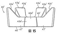
ミッドソール31’は主にポリウレタンまたはエチルビニルアセテートなどの発泡ポリマー材料で形成され、図9および図10に示すように、チャンバー40’はミッドソール31’の踵部分の中に配設されている。図11〜図15ではチャンバー40’だけを取り出して図示してあるが、中央部分41’、7つの分岐部42a’〜42g’、および対応する7つの先端部43a’〜43g’を含む。更にチャンバー40’は参照のための軸44’、第一の表面45’、第二の表面46’および側壁47’を有する。チャンバー40’は軸44’を通って延びる平面であって、第一の表面45’および第二の表面46’の平面に概略垂直である平面に関して対称であるが、その他では非対称である。チャンバー40’はほぼ平面的な形状の表面45および46を有するが、チャンバー40’の第一の表面45’はカーブした形状を有する。すなわち、第一の表面45’において、先端部43a’〜43c’および43e’〜43g’に隣接する部分は上に向かって曲がり、丸みのある、つまり凹形の構造を形成する。それに対して、第一の表面45’において、分岐部42d’上の部分はほぼ平面の形状を有する。
The midsole 31 'is mainly formed of a foamed polymer material such as polyurethane or ethyl vinyl acetate, and the chamber 40' is disposed in the heel portion of the midsole 31 'as shown in FIGS. . 11 to 15 show only the chamber 40 'taken out, it includes a central portion 41', seven
図9および図10において、ミッドソール31’内のチャンバー40’の位置が図示されている。チャンバー40’は概略、第二の表面46’がミッドソール31’内の発泡材料の下面と同一面内にあるように配設されている。この構成により、ミッドソール31’内の発泡材料の一部が足と第一の表面45’との間に配置されることになる。先端部43a’〜43c’および43e’〜43g’もまたミッドソール31’の縁と同じ面を共有する。そのため、先端部43a’〜43c’および43e’〜43g’は靴10’の外側から見える。第二の表面46’のカーブした形状のために、分岐部42a’〜42c’および42e’〜42g’は、中央部分41’から先端部43a’〜43c’および43e’〜43g’へと放射状に外に向かうにつれて高さおよび体積が増加する。体積が増加することにより、圧縮中により多くの流体が中央部分41’から先端部43a’〜43c’および43e’〜43g’へと移動することが可能になり、その結果比較的柔軟なクッション反応から比較的硬いクッション反応への、より緩やかな移行が実現する。更にまた、先端部43a’〜43c’および43e’〜43g’における体積の増加により、所定の程度の圧縮に対してチャンバー40’内に生じる全体の流体圧力が低減される。
9 and 10, the position of the chamber 40 'within the midsole 31' is illustrated. Chamber 40 'is generally arranged such that second surface 46' is flush with the lower surface of the foam material in midsole 31 '. This configuration results in a portion of the foam material in the midsole 31 'being disposed between the foot and the first surface 45'. The
図13B〜図13Dの断面図に示されている側壁47’の傾斜はチャンバー40’周辺で変化して、圧縮中の滑らかな移行を実現する。側壁47は隣接する先端部43a〜43g’の間で傾斜し、先端部43a’〜43e’において実質的に垂直の傾斜となる。隣接する分岐部42a’〜42g’の間の空間は一般にU字形の形状を有するが、これは側壁47’の曲面によって作られる。隣接する分岐部42a’〜42g’の間に位置する側壁47’の部分は、中央部分41’に隣接する領域よりも先端部43a’〜43g’に隣接する領域における方が大きな傾斜を有する。より具体的には、側壁47’は比較的浅い傾斜を中央部分41’に隣接して有するが、これはU字形状の丸い部分に対応する。側壁47’が中央部分41’と先端部43a’〜43e’との間で延びるに従って、傾斜がきつくなる。ただし先端部43a’〜43e’では、側壁47’の傾斜は実質的に垂直となる。
The slope of the side wall 47 'shown in the cross-sectional views of FIGS. 13B-13D varies around the chamber 40' to achieve a smooth transition during compression. The
ランニング中の足の典型的な動きは以下のようになる。先ず踵が地面に当たり、次に親指の付け根のふくらみが地面に当たる。踵が地面から離れると、足の接地点は前に移動してつま先が接触し、最後に足全体が地面から離れて次のサイクルが開始される。足が地面に接触して足の接地点が前に移動する間、接地点は同時に足の外側すなわち側方から内側すなわち中央部に移動するという回内運動と呼ばれるプロセスが行われる。足が空中にあり、次のサイクルの準備をするとき、反対のプロセス、いわゆる回外運動が起きる。チャンバー40は分岐部42a〜42eに対応する領域よりも大きなコンプライアンスを中央部分41に与えることにより、ランニング中の足の運動を補佐し、それにより足の中央側への回動に抵抗する。他の実施形態では、分岐部42a〜42eの寸法と発泡材料の特性または量とを変更して回内運動を制限することができる。同様の考え方がチャンバー40’にも適用される。
The typical movement of the foot while running is as follows. First, the heel hits the ground, then the bulge at the base of the thumb hits the ground. When the heel leaves the ground, the ground point of the foot moves forward and the toes touch, and finally the entire foot leaves the ground and the next cycle begins. While the foot is in contact with the ground and the ground point of the foot moves forward, a process called pronation is performed in which the ground point simultaneously moves from the outside of the foot, that is, from the side to the inside, that is, the center. When the foot is in the air and preparing for the next cycle, the opposite process, the so-called supination movement occurs. The
チャンバー40と同様に、チャンバー40’およびミッドソール31’の発泡体内でのその配置により、最初の圧縮段階で与えられる負荷に応じて生じるたわみが、発明の背景で説明した流体充填チャンバーと比べると、比較的大きなものとなる。しかし、チャンバー40’の圧縮が進行すると、ミッドソール31の構造に対応した態様でチャンバー40’の剛性が高くなる。この効果は、圧力の勾配、ミッドソール31’内の発泡材料の特性およびフィルムの張力の増加の結果でもある。そのため、チャンバー40’の体積、分岐部42a’〜42g’の数および形状、側壁47’の傾斜、表面45’および46’の厚み、チャンバー40’の外面を形成するのに使用される材料、ならびにミッドソール31’内におけるチャンバー40’の位置および向きを変更することで、クッション反応を調整することができる。それに加えて、発泡材料の量、硬度および厚みを含む発泡材料の特性を調整することでも、クッション反応を調整することができる。従って、これらおよびその他のパラメータを変更することにより、ミッドソール31’を特定の個人に合わせてカスタマイズし、または圧縮の間、特定のクッション反応を与えることができる。
Similar to
チャンバー40とチャンバー40’との間の1つの構造的な違いは、第一の表面45’のカーブした形状に関するものである。カーブした形状を有することで、フィルムの張力の増加がクッション反応に及ぼす影響が、第一の表面45’の下向きの角度による圧縮の間に、より迅速に起きることになる。すなわち、チャンバー40’の与えられた大きさのたわみに対して、第一の表面45’が曲がったときにフィルムの張力の増加がクッション反応に対してより大きな影響及ぼすことになる。更にまたカーブした形状により、チャンバー40’はチャンバー40の流体の体積よりも大きな流体の体積を有することができるが、剛性はほぼ同じままとなる。
One structural difference between
本発明の範囲内の多くのチャンバーの構成の例として、チャンバー40およびチャンバー40’を説明してきた。一般に、チャンバーは分岐部を形成する1対の対向する表面をチャンバー内に有する。ここまで、チャンバー40およびチャンバー40’はそれぞれ5つおよび7つの分岐部を有するものとして説明してきた。しかし他の実施形態においては、チャンバーは例えば3つから20までの範囲の任意の数の分岐部を有することができる。
製造方法
ブロー成型プロセスでチャンバー40’を製造する方法を、以下図16〜図25を参照して説明する。靴のチャンバーを形成するための従来のブロー成型プロセスでは、一般に中空で筒形構造の溶融ポリマー材料、別の言い方をすればパリソンが、金型の対応する部分の間に配設される。次に金型をパリソン上に閉じて、溶融ポリマー材料の一部を金型の中に引き込み、金型の形状に適合させる。最後に、金型がパリソンの対向する両側を互いに圧縮して、対向する両側の間に接合部を形成する。しかしある種のブロー成型プロセスでは、製造工程の後の段階で圧縮された流体を注入できるように入口が開放したまま残り、その後入口は封止される。
The
Manufacturing Method A method of manufacturing the
上で説明した従来のブロー成型プロセスでは、2つの対応する金型部分を有する金型が一般的に使用される。各金型部分は一般に平面の表面と、表面に形成された凹部とを有し、凹部の形状はチャンバーの形状の半分に対応する。そのため金型の各部分を閉じて合わせると、金型の中にチャンバーの形状の空洞が形成される。
従来の金型構造を使った場合の1つの結果は、パリソンが凹部内に広がるために伸びなければならず、また伸びることによってパリソンの壁の全体的な厚みを低減させることである。伸びることの影響を相殺するために、パリソンは一般に伸びたときに所望の薄い肉厚となるような初期の肉厚をもって構成される。パリソンが概略一様に伸びるような金型形状である場合、伸びることの影響をこのように相殺することが適切である。しかし、パリソンの伸びのある部分の膨張率が他の部分の膨張率よりも大きいような金型形状である場合、パリソンの肉厚を単に増加させただけでは、その結果生じるチャンバーの肉厚の変化のために、不適切となる場合がある。
In the conventional blow molding process described above, a mold having two corresponding mold parts is commonly used. Each mold part generally has a planar surface and a recess formed in the surface, the shape of the recess corresponding to half the shape of the chamber. Therefore, when each part of the mold is closed and matched, a chamber-shaped cavity is formed in the mold.
One consequence of using a conventional mold structure is that the parison must stretch in order to spread into the recess and reduce the overall thickness of the parison wall by stretching. In order to offset the effects of stretching, the parison is typically constructed with an initial wall thickness that will result in the desired thin wall thickness when stretched. If the parison has a mold shape that extends substantially uniformly, it is appropriate to offset the effects of elongation in this way. However, if the expansion rate of the part of the parison is larger than that of the other part, simply increasing the wall thickness of the parison will result in a reduction in the resulting chamber wall thickness. May be inappropriate due to change.
大略的に平面的な表面と、チャンバー40’の形状を有する空洞を形成する凹部とを有する従来の金型部分は一般に、パリソンの特定の部分を他の部分よりも実質的に長く伸ばすようなタイプのものである。例えば、先端部43a’〜43g’が第一の表面45’と接合するチャンバー40’の領域を形成するパリソンの部分は、中央部分41’を形成するパリソンの部分よりも実質的に長く伸びる。そのため、先端部43a’〜43g’と第一の表面45’との接合部でのチャンバー40’の厚みは、中央部分41’でのチャンバー40’の厚みよりも実質的に小さくなる。しかし、以下で説明するチャンバー40’を製造する方法は、実質的に一様な厚みを有する第一の表面45’、第二の表面46’および側壁47’の各々を形成するブロー成型方法を提供する。
A conventional mold part having a generally planar surface and a recess that forms a cavity having the shape of a chamber 40 'generally extends one part of the parison substantially longer than the other part. Of the type. For example, the portion of the parison that forms the region of the chamber 40 'where the
通常の金型構造の別の結果は、得られるチャンバーの側壁の中央に型割(分割)線が形成されることである。上で述べたように、金型がパリソンの対向する両側を互いに圧縮して、対向する両側の間に接合部を形成する。この接合部が型割線を表し、金型の対向する各部が接触した部分に対応する。ある種の靴の用途では、チャンバーの側壁が眼に見える。そのため側壁の中央に位置する型割線は、チャンバーの美観を損なう。しかし、チャンバー40’を製造する方法は、側壁47’の中央から離れた位置、特に先端部43a’〜43g’に対応する領域から離れた位置に型割線を形成するブロー成型方法を提供する。
Another result of the normal mold structure is that a parting line is formed in the center of the resulting chamber sidewall. As mentioned above, the mold compresses the opposing sides of the parison together to form a joint between the opposing sides. This joint portion represents a parting line, and corresponds to a portion where opposing portions of the mold are in contact with each other. In some shoe applications, the side walls of the chamber are visible. Therefore, the parting line located at the center of the side wall impairs the aesthetic appearance of the chamber. However, the method for manufacturing the
チャンバー40’の形成に利用できる金型(鋳型)100を図16〜図18に示す。金型100は第一の金型部分110と対応する第二の金型部分120を含む。金型部分110および120を合体すると、チャンバー40’の外部寸法とほぼ等しい寸法を有する空洞が形成される。ブロー成型プロセスで靴のチャンバーを形成するための従来の金型と異なり、金型部分110および120はチャンバー40’を形成する空洞に隣接する大略的に平面的な表面を持たない。その代わりに図16に示すように、第一の金型部分110には複数の凹み111a〜111cおよび111e〜111gが規定されており、第二の金型部分120には複数の突起121a〜121cおよび121e〜121gが規定されている。
A mold (mold) 100 that can be used to form the
第一の金型部分110だけを取り出して図17に示すが、これは第一の表面45’と中央部分41’とに隣接して位置する側壁47’の領域に対応するチャンバー40’の部分を形成する。第一の金型部分110はまた、先端部43d’に対応する側壁47’の領域も形成する。第一の金型部分110の中央に位置する領域を囲んで峰部112が延びている。以下でより詳しく説明するように、峰部112はチャンバー40’の型割線が形成される一因となる。そのため、峰部112によって囲まれた区域の中に位置する第一の金型部分110の領域は、第一の表面45’および側壁47’の部分を形成する。より具体的には、中央部分113に近接して位置する第一の金型部分110の表面は、概略中央部分41’を形成し、複数の分岐部の領域114a〜114gの周囲に位置する表面は概略第一の表面45’上の分岐部42a’〜42g’を形成し、側壁の領域115a〜115gの周囲に位置する表面は、概略中央部分41’に隣接して位置する側壁47’の部分を形成する。
Only the
先端部43a’〜43c’および43e’〜43g’に隣接する第一の表面45’の部分は上に向かって曲がり、チャンバー40’に関して述べたように、丸くなった、すなわち凹形の構造を形成する。この形状を形成するために、峰部112によって囲まれた区域の中に位置する第一の金型部分110の領域は、対応する凸形の形状を有する。従って、第一の金型部分110の表面は、中央領域113から側壁の領域114a〜114cおよび114e〜114gまでカーブした形状を有する。
The portion of the first surface 45 'adjacent to the
峰部112の延長部は側壁の領域114dから外側に延びてL字形の通路116を形成している。以下でより詳しく説明するように、チャンバー40’内に流体を注入するための管路を形成するために、通路116が使用される。第一の金型部分110のもう1つの特徴は、中央の領域113と側壁の領域114a〜114gとの全体に分布した複数の空気抜きスロット(孔)117である。空気抜きスロット117は、チャンバー40’を形成する際にパリソンを第一の金型部分110の中に引き込むための空気の出口となるものである。
An extension of the
第二の金型部分120だけを取り出して図18に示すが、これは第二の表面46’と先端部43a’〜43c’および43e’〜43g’に対応する側壁47’との領域に対応するチャンバー40’の部分を形成する。第二の金型部分120の中央に位置する区域を囲んで峰部122が延びており、峰部122は峰部112と協働してチャンバー40’に型割線を形成する。従って、第一の金型部分110と第二の金型部分120とを合体すると、峰部112は峰部122にすぐ隣接する位置に置かれる。峰部122によって囲まれた区域の中に位置する第二の金型部分120の領域は、第二の表面46’と、先端部43a’〜43c’および43e’〜43g’とに対応する側壁47’の部分とを形成する。より具体的には、中央部分123に近接して位置する第二の金型部分120の表面は、概略中央部分41’を形成し、複数の分岐部の領域124a〜124gの周囲に位置する表面は、概略第二の表面46’上の分岐部42a’〜42g’の部分を形成し、先端領域125a〜125cおよび125e〜125gの周囲に位置する表面は、概略先端部43a’〜43c’および43e’〜43g’に対応する側壁47’の部分を形成する。
Only the
チャンバー40’を参照して、第二の表面46’は大略的に平面的な形状を有する。中央部分123と分岐部の領域124a〜124gとに対応する第二の金型部分120の領域は第二の表面46’を形成しており、同様に大略的に平面的な形状を有する。先端領域125a〜125cおよび125e〜125gはそれぞれ分岐部の領域124a〜124cおよび124e〜124gから上向きに延びて先端部43a’〜43c’および43e’〜43g’を形成するための大略的に平面的な領域を与える。峰部122の延長部は分岐部の領域124dから外側に延びてL字形の通路126を形成している。通路116と組み合わされて、チャンバー40’内に流体を注入するための管路が形成される。第二の金型部分120もまた、中央の領域123と分岐部の領域124a〜124gとの全体に分布した複数の空気抜きスロット(孔)127を含む。空気抜きスロット117と同様に、空気抜きスロット127はチャンバー40’を形成する際に、パリソンを第二の金型部分120の中に引き込むための空気の出口となるものである。
Referring to chamber 40 ', second surface 46' has a generally planar shape. A region of the
凹み111a〜111cおよび111e〜111gと突起121a〜121cおよび121e〜121gは、チャンバー40’を形成する金型部分110および120の各部から外側に向かって延びている。具体的には、凹み111a〜111cおよび111e〜111gはそれぞれ、分岐部の領域114a〜114cおよび114e〜114gから外側に向かって放射状に延びている。同様に、突起121a〜121cおよび121e〜121gは分岐部の領域124a〜124cおよび124e〜124gから外側に向かって放射状に延びている。従って、凹み111a〜111cおよび111e〜111gと突起121a〜121cおよび121e〜121gは分岐部42a’〜42c’および42e’〜42g’を形成する金型100の各部分と概略位置を合わせて配置される。
The
パリソン130からチャンバー40’を形成するための金型100の使用の仕方について述べる。パリソン130は一般に中空で大略的に筒形の構造の溶融ポリマー材料である。ここで筒形構造という言葉は、円形の横断面を有する円筒形に限定されず、引き伸ばされた形状または長円形の横断面を有する形状をも含むものとする。パリソン130を形成する場合、溶融ポリマー材料をダイから押出す。パリソン130の肉厚はほぼ一定か、またはパリソン130の外周に沿って変化してもよい。従って、パリソン130の断面図は肉厚の異なる領域を示す可能性がある。パリソン130に適した材料は、チャンバー40およびチャンバー40’について上で述べた材料を含む。
A method of using the
上記のようにパリソン130を形成した後、図19に示すようにパリソン130は金型の部分110と部分120との間に垂れ下がることになる。説明のために、パリソン130は第一の金型部分110に面した第一の側131と第二の金型部分120に面した第二の側132とを有する。次に金型の部分110および120の位置を合わせて、凹み111a〜111cおよび111e〜111gが突起121a〜121cおよび121e〜121gにそれぞれ対応するようにする。この位置では、チャンバー40’を形成する金型の部分110と部分120との各領域はパリソン130の両側に配置され、同様に互いに位置合わせされている。次に金型の部分110および120を互いに向けて移動し、図20に示すように金型100がパリソン130に接触するようにする。具体的には、その中に凹み111a〜111cおよび111e〜111gが形成されている第一の金型部分110の表面が第一の側131に接触し、突起121a〜121cおよび121e〜121gを形成する第二の金型部分120の表面が第二の側132に接触する。
After the
金型100がパリソン130に接触するとパリソン130の各部が曲がり、図20に示すように、金型の各部110および120が互いに更に接近できるようになる。具体的には、第一の表面131は凹み111a〜111cおよび111e〜111gの中に入るように曲がり、第二の表面132は突起121a〜121cおよび121e〜121gの周囲に位置するように曲がる。その結果、金型の各部110および120が互いに接近する間、パリソン130は曲がり続ける。
When the
金型の各部110および120が互いに更に接近すると、突起121a〜121cおよび121e〜121gは完全に凹み111a〜111cおよび111e〜111gの中に入り、パリソン130の片側131はパリソン130の片側132に押し付けられ、図21に示すように片側131の部分を片側132に接着する。しかし、パリソン130の中央部分は、チャンバー40’を形成するための金型100の表面に接触してそれに形を合わせる。そのため、第一の片側131の中央領域は中央部分113、分岐部114a〜114g、および側壁領域115a〜115gに接触してその形状に適合する。同様に、第二の片側132の中央領域は中央部分123、分岐部124a〜124g、および先端部の領域125a〜125cおよび125e〜125gに接触してその形状に適合する。更に、峰部112および122は片側131および132を互いに押し付けることにより、チャンバー40’の外周部分を封止する接着を行なう。
As the
金型100を閉じると、大気圧に対してプラスの圧力を有する空気などの流体を片側131および132の間に注入することができ、それによりパリソン130を金型部分110および120に接触させてその形状に適合させる。最初、流体はパリソン130を形成するダイ機構から供給し、パリソン130の長手方向に沿って流し、片側131および132が互いに接触するのを防止することができる。しかし、金型100がパリソン130をはさんで閉じると、流体を通路116および126によって形成された管路を通して流すことができる。例えば、針でパリソン130の管路への入口部分に穴を開け、流体を管路を通してチャンバー40’形成領域に流し込むことができる。パリソン130と金型部分110および120との間の空気は空気抜きスロット117および127を通して抜き出すことができ、それによりパリソン130を金型部分110および120の表面に吸引する。
When the
金型100内にチャンバー40’が形成されると、金型部分110および120を分離して、図23〜図24に示すようにパリソンを金型100から取り出すことができる。そして、パリソン130を形成するポリマー材料を冷却し、通路116および126によって形成された管路を封止して流体をチャンバー40’内に大気圧で封入することができる。あるいは、圧縮した流体を管路を通って注入してから封止することもできる。更に、パリソン130の余分な部分をトリミングその他の方法でチャンバー40’から取り除くことができる。余分な部分はリサイクルするか、または他のパリソンを形成するときに利用できる。
Once the chamber 40 'is formed in the
上の議論によれば、金型部分110および120は各々一般にそれぞれ異なる機能を有する屈曲ゾーンと形成ゾーンとを含む。第一の金型部分110では、屈曲ゾーンは凹み111a〜111cおよび111e〜111gを含む。従って、屈曲ゾーンは接着前のパリソン130を曲げる役割を果たす。形成ゾーンは中央部分113、分岐部の領域114a〜114gおよび側壁の領域115a〜115gを含む。従って、形成ゾーンはチャンバー40’の実際の形状をパリソンに与える役割を果たす。すなわち、形成ゾーンはチャンバー40’の第一の表面45’と側壁47’の部分とを実際に形成する。同様に、第二の金型部分120の屈曲ゾーンは突起121a〜121cおよび121e〜121gを含み、やはり接着前のパリソン130を曲げる役割を果たす。第二の金型部分120の形成ゾーンは中央部分123、分岐部の領域124a〜124gならびに先端領域125a〜125cおよび125e〜125gを含み、形成ゾーンはチャンバー40’の第二の表面46’と側壁47’の他の部分とを実際に形成する。このように、金型の部分110および120は各々、パリソンを曲げる屈曲ゾーンとチャンバー47’の各部を形成する形成ゾーンとを含み、屈曲ゾーンは形成ゾーンとは別である。
According to the above discussion,
上で述べたように、金型の部分110および120が最初にパリソン130に接触するとき、片側131および132は曲げられる。しかし、パリソン130のある部分は、接触してチャンバー40’を形成する様々な表面に適合するために伸びることができる。金型の部分110および120が最初にパリソン130に接触するときに各片側131および132を曲げる目的は、パリソン130の伸びを一様にすることである。すなわち、パリソン130を曲げることにより、各片側131および132が大略的に一様な仕方で伸びることが保証され、それによりチャンバー40’の第一の表面45’、第二の表面46’および側壁47’の厚みがほぼ一様になる。
As noted above, when
各片側131および132を曲げることの別の利点は、金型の対向する各部が袋状部材40’に隣接して出合う領域に対応する型割線133の位置に関するものである。すなわち型割線133は、峰部112および122によって形成される片側131および132の間でのチャンバー40’内の接合部である。図26では型割線133の位置は参照のために破線で示されている。通常のブロー成型工程で形成された従来の多くのチャンバーでは、型割線は側壁を水平に横切って真っ直ぐ延び、側壁の部分をぼかしてしまう。しかしチャンバー40’では、型割線133は側壁47’を横切って上下(垂直方向)に延びるだけではない。型割線133は先端部43a’〜43g’の周囲に延びて波状のパターンを有する非直線的なコースをたどるのである。より具体的には、型割線133は先端部43a’〜43c’および43e’〜43g’の上端において、側壁47’と第一の表面45’との間を水平に延びる。次に、型割線133は側壁47’を横切り、先端部43a’〜43c’および43e’〜43g’の側面に沿って上下に延びる。従って、型割線133の少なくとも一部は第一の表面45’と第二の表面46’との間を通って延びている。型割線133はまた、分岐部42a’〜42g’の間の領域で、側壁47’と第二の表面46’との間を水平に延びる。図8に示すように靴の中に組み込まれると、型割線133は一般に眼に見えず、チャンバー40’の見える部分である先端部43a’〜43g’を横切って延びることはない。従って、型割線133は側壁47’の中央には位置しない。
Another advantage of bending each
非直線的な型割線133を形成することの1つの結果は、側壁47’の特定の部分が片側131または132から形成されるということである。例えば、中央部分41’に隣接する側壁47’の領域をここで第一の領域と呼ぶことにすると、この領域は第一の片側131によって形成される。従って、側壁47’の第一の領域は第一の表面45’から第二の表面46’に向かって延び、第一の片側131から形成される。同様に、先端部43a’〜43c’および43e’〜43g’を形成する側壁47’の領域をここで第二の領域と呼ぶことにすると、この領域は第二の片側132から形成される。従って、側壁47’の第二の領域もまた、第一の表面45’から第二の表面46’に向かって延び、第二の片側132から形成される。概して、第一の領域と第二の領域とが互いにからんで側壁47’を形成するように、第一の領域と第二の領域は交互に現れる。
One result of forming the
上で説明したブロー成型工程は、靴のチャンバーを形成するための通常のブロー成型工程とは異なる。例えば、金型100はパリソン130を接着するまたは伸ばす前にそれを曲げるために複数の凹み111a〜111cおよび111e〜111gと複数の突起121a〜121cおよび121e〜121gとを含み、それによりチャンバー40’の肉厚を一様にする。更に、パリソン130を曲げることにより、側壁47’の見える部分を横切って延びることがなく、中央に位置しない型割線133が形成される。
結論
添付図面を参照し、様々な実施形態について本発明を説明してきた。しかし、この説明の目的は本発明に関わる様々な特徴および考え方の一例を示すことであり、本発明の範囲を限定することではない。当業者であれば、本発明の範囲から逸脱することなく、多くの変形や変更を上記の実施形態に対して行なうことができることを理解するであろう。本発明の範囲は添付の特許請求の範囲によって規定されるものである。
The blow molding process described above is different from the normal blow molding process for forming a shoe chamber. For example, the
CONCLUSION The present invention has been described in terms of various embodiments with reference to the accompanying drawings. However, the purpose of this description is to show an example of various features and concepts related to the present invention, and not to limit the scope of the present invention. Those skilled in the art will appreciate that many variations and modifications can be made to the above-described embodiments without departing from the scope of the present invention. The scope of the present invention is defined by the appended claims.
Claims (40)
金型の第一の部分と、対応する第二の部分との間にパリソンを配置する工程と、
前記第一の部分と前記第二の部分とが互いに向かって移動する際に、前記金型の外形に合わせて前記パリソンを曲げる工程であって、前記金型の外形は前記金型内部の空洞から離れて配置され、前記空洞は前記チャンバーの形状を有している工程と、
前記パリソンの両側部分を成形して、前記空洞内に前記チャンバーを形成する工程と、
前記パリソンの対向する両側部分を互いに接着する工程とを含む方法。A method for manufacturing a fluid-filled chamber for footwear, comprising:
Placing a parison between the first part of the mold and the corresponding second part;
Bending the parison according to the outer shape of the mold when the first part and the second part move toward each other, the outer shape of the mold being a cavity inside the mold Disposed away from the cavity, the cavity having the shape of the chamber;
Molding both sides of the parison to form the chamber in the cavity;
Adhering opposing opposing portions of the parison together.
金型の第一の部分と、対応する第二の部分との間にパリソンを配置する工程と、
前記パリソンの両側部分を成形して、前記金型内部の空洞内でチャンバーを形成する工程であって、前記空洞が前記チャンバーの形状を有している工程と、
前記パリソンの前記両側部分を互いに接着して、型割線を規定する工程であって、前記型割線の少なくとも一部分が前記チャンバーの第一の表面およびこの第一の表面に対向する第二の表面に関して中心から外れるように配置される工程とを含む方法。A method for manufacturing a fluid-filled chamber for footwear, comprising:
Placing a parison between the first part of the mold and the corresponding second part;
Forming both sides of the parison and forming a chamber in the cavity inside the mold, wherein the cavity has the shape of the chamber;
Adhering the two side portions of the parison together to define a parting line, wherein at least a portion of the parting line relates to a first surface of the chamber and a second surface opposite the first surface And a step of being disposed off-center.
金型の第一の部分と、対応する第二の部分との間にパリソンを配置する工程であって、前記パリソンが前記第一の部分に面する第一の側を有するとともに、前記パリソンが前記第二の部分に面する第二の側を有する工程と、
前記第一の部分と前記第二の部分とを互いに向けて移動する際に、前記金型の外形に合わせて前記パリソンを曲げる工程と、
前記パリソンを成形して前記チャンバーの第一の表面、第二の表面および側壁を規定する工程であって、前記側壁の少なくとも第一の領域が前記第一の側から形成され、前記第一の領域は前記第一の表面から前記第二の表面まで延び、前記側壁の少なくとも第二の領域が前記第二の側から形成され、前記第二の領域もまた前記第一の表面から前記第二の表面まで延びる工程と、
前記パリソンの前記第一の側を前記パリソンの前記第二の側に接着して型割線を形成する工程とを含む方法。A method for manufacturing a fluid-filled chamber for footwear, comprising:
Placing a parison between a first part of a mold and a corresponding second part, the parison having a first side facing the first part, the parison being Having a second side facing the second portion;
Bending the parison according to the outer shape of the mold when moving the first part and the second part toward each other;
Forming the parison to define a first surface, a second surface and a sidewall of the chamber, wherein at least a first region of the sidewall is formed from the first side; A region extends from the first surface to the second surface, at least a second region of the sidewall is formed from the second side, and the second region is also from the first surface to the second surface. Extending to the surface of
Bonding the first side of the parison to the second side of the parison to form a parting line.
第一の部分および対応する第二の部分を有する金型を用意する工程であって、前記第一の部分および前記第二の部分の一方が突起を含み、前記第一の部分および前記第二の部分の他方が前記突起を受ける凹みを含み、前記凹みおよび前記突起が前記金型の前記チャンバーを形成する領域から離れて配置されるようになされた金型を用意する工程と、
前記金型の前記第一の部分と前記第二の位置との間にパリソンを配置する工程であって、前記パリソンが前記第一の部分に面する第一の側を有するとともに、前記パリソンが前記第二の部分に面する第二の側を有するようにする工程と、
前記第一の部分と前記第二の部分とを互いに向け移動して前記パリソンに接触させる際に、前記突起を回り込み前記凹みに入るように前記パリソンを曲げる工程と、
前記第一の側から第一の表面を形成し、前記第二の側から第二の表面を形成して前記パリソンを成形する工程であって、前記第一の側と前記第二の側とが組み合わされて前記チャンバーの側壁の少なくとも一部分を形成する工程と、
前記パリソンの対向する両側を互いに接着する工程とを含む方法。A method for manufacturing a fluid-filled chamber for footwear, comprising:
Providing a mold having a first part and a corresponding second part, wherein one of the first part and the second part includes a protrusion, the first part and the second part; Providing a mold in which the other part includes a recess for receiving the protrusion, and the recess and the protrusion are arranged apart from a region of the mold forming the chamber;
Placing a parison between the first portion of the mold and the second position, the parison having a first side facing the first portion, the parison being Having a second side facing the second portion;
When the first part and the second part are moved toward each other and brought into contact with the parison, bending the parison around the protrusion and entering the recess;
Forming the first surface from the first side and forming the second surface from the second side to form the parison, wherein the first side and the second side; In combination to form at least a portion of the sidewall of the chamber;
Adhering opposing sides of the parison to each other.
Applications Claiming Priority (2)
| Application Number | Priority Date | Filing Date | Title |
|---|---|---|---|
| US10/620,843 US7128796B2 (en) | 2003-07-16 | 2003-07-16 | Footwear with a sole structure incorporating a lobed fluid-filled chamber |
| PCT/US2004/019092 WO2005009164A1 (en) | 2003-07-16 | 2004-06-23 | Footwear with a sole structure incorporating a lobed fluid-filled chamber |
Publications (2)
| Publication Number | Publication Date |
|---|---|
| JP2007530308A JP2007530308A (en) | 2007-11-01 |
| JP4272674B2 true JP4272674B2 (en) | 2009-06-03 |
Family
ID=34062857
Family Applications (1)
| Application Number | Title | Priority Date | Filing Date |
|---|---|---|---|
| JP2006520174A Active JP4272674B2 (en) | 2003-07-16 | 2004-06-23 | Footwear having a bottom structure incorporating a branched fluid-filled chamber |
Country Status (12)
| Country | Link |
|---|---|
| US (2) | US7128796B2 (en) |
| EP (1) | EP1643876B1 (en) |
| JP (1) | JP4272674B2 (en) |
| CN (1) | CN100409783C (en) |
| AT (1) | ATE416643T1 (en) |
| AU (1) | AU2004258843B2 (en) |
| BR (1) | BRPI0412431B1 (en) |
| CA (1) | CA2531720C (en) |
| DE (1) | DE602004018316D1 (en) |
| HK (1) | HK1084837A1 (en) |
| WO (1) | WO2005009164A1 (en) |
| ZA (1) | ZA200600199B (en) |
Cited By (1)
| Publication number | Priority date | Publication date | Assignee | Title |
|---|---|---|---|---|
| KR102061710B1 (en) | 2013-02-21 | 2020-01-02 | 나이키 이노베이트 씨.브이. | Article of footwear incorporating a chamber system and methods for manufacturing the chamber system |
Families Citing this family (30)
| Publication number | Priority date | Publication date | Assignee | Title |
|---|---|---|---|---|
| US7707744B2 (en) * | 2003-07-16 | 2010-05-04 | Nike, Inc. | Footwear with a sole structure incorporating a lobed fluid-filled chamber |
| US7707745B2 (en) | 2003-07-16 | 2010-05-04 | Nike, Inc. | Footwear with a sole structure incorporating a lobed fluid-filled chamber |
| US7562469B2 (en) | 2003-12-23 | 2009-07-21 | Nike, Inc. | Footwear with fluid-filled bladder and a reinforcing structure |
| US7401369B2 (en) * | 2005-04-14 | 2008-07-22 | Nike, Inc. | Fluid-filled bladder for footwear and other applications |
| US7513066B2 (en) * | 2005-04-14 | 2009-04-07 | Nike, Inc. | Fluid-filled bladder for footwear and other applications |
| US20060273496A1 (en) * | 2005-06-02 | 2006-12-07 | Tay-Yuo Chen | Method of making outsole |
| ITBO20060288A1 (en) * | 2006-04-14 | 2007-10-15 | Ideaslab Snc | SHOE MAKING AND RELATIVE PROCEDURE OF REALIZATION. |
| US7810255B2 (en) | 2007-02-06 | 2010-10-12 | Nike, Inc. | Interlocking fluid-filled chambers for an article of footwear |
| DE102007008741A1 (en) * | 2007-02-22 | 2008-08-28 | Siemens Ag | Cushion for fixing shoulders of patients in magnetic resonance imaging |
| US7941941B2 (en) | 2007-07-13 | 2011-05-17 | Nike, Inc. | Article of footwear incorporating foam-filled elements and methods for manufacturing the foam-filled elements |
| FR2919155B1 (en) * | 2007-07-25 | 2009-10-16 | Bernard Favraud | "WEAR SOLE FOR FOOTWEAR AND METHOD AND MOLD FOR MANUFACTURING SAID SOLE" |
| US8241450B2 (en) | 2007-12-17 | 2012-08-14 | Nike, Inc. | Method for inflating a fluid-filled chamber |
| US8178022B2 (en) | 2007-12-17 | 2012-05-15 | Nike, Inc. | Method of manufacturing an article of footwear with a fluid-filled chamber |
| US8863408B2 (en) | 2007-12-17 | 2014-10-21 | Nike, Inc. | Article of footwear having a sole structure with a fluid-filled chamber |
| US8341857B2 (en) * | 2008-01-16 | 2013-01-01 | Nike, Inc. | Fluid-filled chamber with a reinforced surface |
| US8572867B2 (en) * | 2008-01-16 | 2013-11-05 | Nike, Inc. | Fluid-filled chamber with a reinforcing element |
| US7867435B2 (en) * | 2008-03-21 | 2011-01-11 | Boston Scientific Scimed, Inc. | Manufacture of inflatable member for bifurcation catheter assembly |
| US8650775B2 (en) | 2009-06-25 | 2014-02-18 | Nike, Inc. | Article of footwear having a sole structure with perimeter and central elements |
| US9119439B2 (en) | 2009-12-03 | 2015-09-01 | Nike, Inc. | Fluid-filled structure |
| US8991072B2 (en) | 2010-02-22 | 2015-03-31 | Nike, Inc. | Fluid-filled chamber incorporating a flexible plate |
| US8470113B2 (en) * | 2010-05-12 | 2013-06-25 | Nike, Inc. | Method of manufacturing a contoured fluid-filled chamber with a tensile member |
| US9144265B2 (en) | 2011-09-14 | 2015-09-29 | Shoes For Crews, Llc | Shoe with support system |
| US9380832B2 (en) | 2012-12-20 | 2016-07-05 | Nike, Inc. | Article of footwear with fluid-filled chamber lacking an inflation channel and method for making the same |
| US10806214B2 (en) | 2013-03-08 | 2020-10-20 | Nike, Inc. | Footwear fluid-filled chamber having central tensile feature |
| US9480298B2 (en) * | 2013-08-01 | 2016-11-01 | Nike, Inc. | Article of footwear with support assembly having primary and secondary members |
| US9687044B2 (en) | 2014-07-24 | 2017-06-27 | Nike, Inc. | Footwear with sole structure incorporating lobed fluid-filled chamber with protruding end wall portions |
| WO2017115402A1 (en) * | 2015-12-28 | 2017-07-06 | 株式会社アシックス | Footwear |
| EP3568034B1 (en) * | 2017-04-11 | 2022-03-02 | NIKE Innovate C.V. | Articles of footwear including a multi-part sole structure |
| USD876057S1 (en) * | 2019-02-01 | 2020-02-25 | Nike, Inc. | Shoe |
| KR20220098248A (en) * | 2019-11-19 | 2022-07-11 | 나이키 이노베이트 씨.브이. | Sole structure for articles of footwear |
Family Cites Families (142)
| Publication number | Priority date | Publication date | Assignee | Title |
|---|---|---|---|---|
| US1323610A (en) | 1919-12-02 | price | ||
| US900867A (en) | 1907-06-24 | 1908-10-13 | Benjamin N B Miller | Cushion for footwear. |
| US1069001A (en) * | 1913-01-14 | 1913-07-29 | William H Guy | Cushioned sole and heel for shoes. |
| US1240153A (en) | 1916-01-07 | 1917-09-11 | Keene Shock Absorber Company | Pneumatic cushion for shoes. |
| US1304915A (en) * | 1918-07-31 | 1919-05-27 | Burton A Spinney | Pneumatic insole. |
| US1584034A (en) * | 1922-06-05 | 1926-05-11 | Klotz Alfred | Pneumatic insertion for shoes |
| US1514468A (en) | 1922-08-02 | 1924-11-04 | John P W Schopf | Arch cushion |
| US1625582A (en) * | 1924-11-10 | 1927-04-19 | Airubber Corp | Flexible hollow articles and method of making the same |
| US1793703A (en) * | 1925-02-27 | 1931-02-24 | Krichbaum Ora | Rubber article |
| US1869257A (en) * | 1929-12-10 | 1932-07-26 | Hitzler Theodor | Insole |
| US1916483A (en) * | 1930-03-14 | 1933-07-04 | Krichbaum Ora | Inflatable article |
| US1970803A (en) * | 1932-10-03 | 1934-08-21 | Johnson John Herbert | Method of making an inflatable rubber structure |
| US2080469A (en) * | 1933-05-17 | 1937-05-18 | Levi L Gilbert | Pneumatic foot support |
| US2004906A (en) * | 1934-03-05 | 1935-06-11 | Joseph Farese | Pneumatic shoe |
| US2086389A (en) * | 1936-09-24 | 1937-07-06 | Pearson Susan Clare | Inflated arch support and ventilated heel cushion |
| US2269342A (en) * | 1938-05-31 | 1942-01-06 | K & W Rubber Corp | Inflatable rubber goods |
| US2365807A (en) | 1943-04-17 | 1944-12-26 | Emmanuel M Dialynas | Pneumatic or cushion arch support for shoes |
| US2488382A (en) | 1946-06-07 | 1949-11-15 | Whitman W Davis | Pneumatic foot support |
| US2546827A (en) * | 1948-10-02 | 1951-03-27 | Lavinthal Albert | Arch supporting device |
| US2600239A (en) * | 1949-11-01 | 1952-06-10 | Levi L Gilbert | Pneumatic insole |
| US2703770A (en) * | 1952-04-15 | 1955-03-08 | Melzer Jean | Manufacture of flat inflatable objects |
| US2748401A (en) * | 1952-06-30 | 1956-06-05 | Hedwin Corp | Extruded flexible and hollow articles and method of making same |
| US2645865A (en) * | 1952-07-25 | 1953-07-21 | Edward W Town | Cushioning insole for shoes |
| US2677906A (en) * | 1952-08-14 | 1954-05-11 | Reed Arnold | Cushioned inner sole for shoes and meth od of making the same |
| US2762134A (en) | 1954-07-30 | 1956-09-11 | Edward W Town | Cushioning insoles for shoes |
| US3048514A (en) * | 1958-09-17 | 1962-08-07 | Us Rubber Co | Methods and apparatus for making inflatable cushions |
| US3030640A (en) * | 1960-01-13 | 1962-04-24 | Air Pillow & Cushions Inc | Inflated articles |
| US3121430A (en) * | 1960-05-10 | 1964-02-18 | Edwin L O'reilly | Inflatable insole with self-fitting arch support |
| US3120712A (en) * | 1961-08-30 | 1964-02-11 | Menken Lester Lambert | Shoe construction |
| DE1454947B1 (en) * | 1963-07-08 | 1971-03-11 | Battenfeld Geb | METHOD AND DEVICE FOR INFLATING OPENED HOLLOW BODIES |
| US3300558A (en) | 1963-07-19 | 1967-01-24 | Walker Mfg Co | Method of removing the cell walls of a resilient cellular filter material |
| US3366525A (en) * | 1964-02-06 | 1968-01-30 | Hexcel Corp | Method of making thermoplastic honeycomb |
| US3204678A (en) | 1964-02-14 | 1965-09-07 | Gurdon S Worcester | Beach bag |
| US3335045A (en) | 1964-06-15 | 1967-08-08 | Post Louis | Method for making an inflatable article |
| US3284264A (en) | 1965-03-01 | 1966-11-08 | Gerald J O'rourke | Method of making a bellows structure of thermosetting material |
| US3251076A (en) * | 1965-03-19 | 1966-05-17 | Daniel M Burke | Impact absorbing mat |
| US3469576A (en) | 1966-10-05 | 1969-09-30 | Henry M Smith | Footwear |
| US3568227A (en) * | 1968-04-10 | 1971-03-09 | Philips Maine Corp | Inflatable cushion and apparatus for making same |
| US3589037A (en) * | 1969-05-27 | 1971-06-29 | John P Gallagher | Foot cushioning support member |
| US3608215A (en) | 1969-06-14 | 1971-09-28 | Tatsuo Fukuoka | Footwear |
| US3685176A (en) * | 1970-07-02 | 1972-08-22 | Marion F Rudy | Inflatable article of footwear |
| US3758964A (en) | 1971-10-25 | 1973-09-18 | Onitsuka Co Ltd | Sports shoe |
| US3765422A (en) | 1971-12-27 | 1973-10-16 | H Smith | Fluid cushion podiatric insole |
| US4129951A (en) | 1976-04-20 | 1978-12-19 | Charles Petrosky | Air cushion shoe base |
| US4017931A (en) * | 1976-05-20 | 1977-04-19 | The Jonathan-Alan Corporation | Liquid filled insoles |
| US4054960A (en) | 1976-06-25 | 1977-10-25 | Pettit John E | Inflatable body support cushion, particularly to support a woman during pregnancy |
| US4183156A (en) * | 1977-01-14 | 1980-01-15 | Robert C. Bogert | Insole construction for articles of footwear |
| US4115934A (en) | 1977-02-11 | 1978-09-26 | Hall John M | Liquid shoe innersole |
| US4217705A (en) * | 1977-03-04 | 1980-08-19 | Donzis Byron A | Self-contained fluid pressure foot support device |
| US4287250A (en) | 1977-10-20 | 1981-09-01 | Robert C. Bogert | Elastomeric cushioning devices for products and objects |
| US4167795A (en) | 1978-04-14 | 1979-09-18 | Liberty Vinyl Corporation | Motion suppressing fluid mattress |
| US4340626A (en) * | 1978-05-05 | 1982-07-20 | Rudy Marion F | Diffusion pumping apparatus self-inflating device |
| US4187620A (en) * | 1978-06-15 | 1980-02-12 | Selner Allen J | Biomechanical shoe |
| US4219945B1 (en) | 1978-06-26 | 1993-10-19 | Robert C. Bogert | Footwear |
| US4305212A (en) | 1978-09-08 | 1981-12-15 | Coomer Sven O | Orthotically dynamic footwear |
| US4297797A (en) | 1978-12-18 | 1981-11-03 | Meyers Stuart R | Therapeutic shoe |
| US4328599A (en) * | 1979-06-27 | 1982-05-11 | Mollura Carlos A | Firmness regulated waterbed mattress |
| US4292702A (en) | 1979-07-20 | 1981-10-06 | Phillips Raymond M | Surge dampened water bed mattress |
| US4271606A (en) * | 1979-10-15 | 1981-06-09 | Robert C. Bogert | Shoes with studded soles |
| US4358902A (en) | 1980-04-02 | 1982-11-16 | Cole George S | Thrust producing shoe sole and heel |
| US4423000A (en) | 1980-10-17 | 1983-12-27 | Syoichi Teraoka | Method for molding hollow plastic articles |
| SE8102124L (en) * | 1981-04-02 | 1982-10-03 | Lars Gustaf Birger Peterson | SOLE |
| AT387323B (en) * | 1981-12-01 | 1989-01-10 | Konsumex Kuelkereskedelmi Vall | Orthopedic shoe insert and / or flat foot insert |
| US4483030A (en) | 1982-05-03 | 1984-11-20 | Medisearch Pr, Inc. | Air pad |
| US4486964A (en) | 1982-06-18 | 1984-12-11 | Rudy Marion F | Spring moderator for articles of footwear |
| US4506460A (en) * | 1982-06-18 | 1985-03-26 | Rudy Marion F | Spring moderator for articles of footwear |
| US4446634A (en) * | 1982-09-28 | 1984-05-08 | Johnson Paul H | Footwear having improved shock absorption |
| US4547919A (en) | 1983-02-17 | 1985-10-22 | Cheng Chung Wang | Inflatable article with reforming and reinforcing structure |
| US4823682A (en) * | 1983-08-12 | 1989-04-25 | Bowles Fluidics Corporation | Vehicle windshield defrost apparatus with reduced dashboard space requirements |
| US4662087A (en) * | 1984-02-21 | 1987-05-05 | Force Distribution, Inc. | Hydraulic fit system for footwear |
| US5104477A (en) * | 1984-10-17 | 1992-04-14 | Bridgestone/Firestone, Inc. | Elastomeric structures having controlled surface release characteristics |
| US4670995A (en) * | 1985-03-13 | 1987-06-09 | Huang Ing Chung | Air cushion shoe sole |
| JPS61226084A (en) * | 1985-03-30 | 1986-10-07 | 株式会社タチエス | Skin member of seat for vehicle and its production |
| US4920591A (en) | 1985-07-16 | 1990-05-01 | Hiroshi Sekido | Air support for chair and method for manufacturing chair utilizing the air support |
| US4803029A (en) * | 1986-01-28 | 1989-02-07 | Pmt Corporation | Process for manufacturing an expandable member |
| US5158767A (en) | 1986-08-29 | 1992-10-27 | Reebok International Ltd. | Athletic shoe having inflatable bladder |
| US4744157A (en) * | 1986-10-03 | 1988-05-17 | Dubner Benjamin B | Custom molding of footgear |
| US4829682A (en) * | 1987-04-27 | 1989-05-16 | Gasbarro Mark A | Sandal sole |
| US5025575A (en) * | 1989-03-14 | 1991-06-25 | Nikola Lakic | Inflatable sole lining for shoes and boots |
| US4991317A (en) * | 1987-05-26 | 1991-02-12 | Nikola Lakic | Inflatable sole lining for shoes and boots |
| US4823482A (en) * | 1987-09-04 | 1989-04-25 | Nikola Lakic | Inner shoe with heat engine for boot or shoe |
| US4782602A (en) | 1987-05-26 | 1988-11-08 | Nikola Lakic | Shoe with foot warmer including an electrical generator |
| US4845338A (en) * | 1988-04-04 | 1989-07-04 | Nikola Lakic | Inflatable boot liner with electrical generator and heater |
| IT1204662B (en) * | 1987-05-29 | 1989-03-10 | Armenak Moumdjian | PNEUMATIC CHAMBER INSOLE FOR FOOTWEAR, MOLD AND FORMING METHOD RELATED |
| US5199191A (en) * | 1987-05-29 | 1993-04-06 | Armenak Moumdjian | Athletic shoe with inflatable mobile inner sole |
| US4779359A (en) | 1987-07-30 | 1988-10-25 | Famolare, Inc. | Shoe construction with air cushioning |
| US4817304A (en) * | 1987-08-31 | 1989-04-04 | Nike, Inc. And Nike International Ltd. | Footwear with adjustable viscoelastic unit |
| US4874640A (en) | 1987-09-21 | 1989-10-17 | Donzis Byron A | Impact absorbing composites and their production |
| US5235715A (en) * | 1987-09-21 | 1993-08-17 | Donzis Byron A | Impact asborbing composites and their production |
| US5046267A (en) * | 1987-11-06 | 1991-09-10 | Nike, Inc. | Athletic shoe with pronation control device |
| US4829882A (en) * | 1987-12-31 | 1989-05-16 | Jackson James S | Crawl space ventilation system |
| US5083361A (en) * | 1988-02-05 | 1992-01-28 | Robert C. Bogert | Pressurizable envelope and method |
| MY106949A (en) * | 1988-02-05 | 1995-08-30 | Rudy Marion F | Pressurizable envelope and method |
| US4906502A (en) * | 1988-02-05 | 1990-03-06 | Robert C. Bogert | Pressurizable envelope and method |
| CA1338369C (en) * | 1988-02-24 | 1996-06-11 | Jean-Pierre Vermeulen | Shock absorbing system for footwear application |
| US4912861A (en) * | 1988-04-11 | 1990-04-03 | Huang Ing Chung | Removable pressure-adjustable shock-absorbing cushion device with an inflation pump for sports goods |
| US4972611A (en) | 1988-08-15 | 1990-11-27 | Ryka, Inc. | Shoe construction with resilient, absorption and visual components based on spherical pocket inclusions |
| US4891855A (en) * | 1988-11-14 | 1990-01-09 | Team Worldwide Corporation | Inflatable suntanner with speedy and homogeneous suntan effect |
| US5042176A (en) * | 1989-01-19 | 1991-08-27 | Robert C. Bogert | Load carrying cushioning device with improved barrier material for control of diffusion pumping |
| US4936029A (en) * | 1989-01-19 | 1990-06-26 | R. C. Bogert | Load carrying cushioning device with improved barrier material for control of diffusion pumping |
| US4999932A (en) * | 1989-02-14 | 1991-03-19 | Royce Medical Company | Variable support shoe |
| US5014449A (en) * | 1989-09-22 | 1991-05-14 | Avia Group International, Inc. | Shoe sole construction |
| US5238231A (en) * | 1990-02-26 | 1993-08-24 | Huang Ing Chung | Shock-absorbing units interconnectable to form shock-absorbing structures |
| US5224277A (en) * | 1990-05-22 | 1993-07-06 | Kim Sang Do | Footwear sole providing ventilation, shock absorption and fashion |
| US5044030A (en) | 1990-06-06 | 1991-09-03 | Fabrico Manufacturing Corporation | Multiple layer fluid-containing cushion |
| US5022109A (en) * | 1990-06-11 | 1991-06-11 | Dielectrics Industries | Inflatable bladder |
| DE4114551C2 (en) * | 1990-11-07 | 2000-07-27 | Adidas Ag | Shoe bottom, in particular for sports shoes |
| US5155927A (en) | 1991-02-20 | 1992-10-20 | Asics Corporation | Shoe comprising liquid cushioning element |
| US5179792A (en) * | 1991-04-05 | 1993-01-19 | Brantingham Charles R | Shoe sole with randomly varying support pattern |
| US5193246A (en) * | 1991-07-23 | 1993-03-16 | Huang Ing Chung | Air cushion grip with a cubic supporting structure and shock-absorbing function |
| US5572804A (en) * | 1991-09-26 | 1996-11-12 | Retama Technology Corp. | Shoe sole component and shoe sole component construction method |
| EP0605485B2 (en) * | 1991-09-26 | 2005-03-30 | Skydex Technologies, Inc. | Shoe sole component |
| US5406719A (en) * | 1991-11-01 | 1995-04-18 | Nike, Inc. | Shoe having adjustable cushioning system |
| US5228156A (en) * | 1992-05-08 | 1993-07-20 | John Wang | Fluid operated device |
| US5224278A (en) * | 1992-09-18 | 1993-07-06 | Jeon Pil D | Midsole having a shock absorbing air bag |
| US5335382A (en) * | 1992-11-23 | 1994-08-09 | Huang Yin Jun | Inflatable cushion device |
| US5625964A (en) * | 1993-03-29 | 1997-05-06 | Nike, Inc. | Athletic shoe with rearfoot strike zone |
| US5425184A (en) * | 1993-03-29 | 1995-06-20 | Nike, Inc. | Athletic shoe with rearfoot strike zone |
| US5771606A (en) * | 1994-10-14 | 1998-06-30 | Reebok International Ltd. | Support and cushioning system for an article of footwear |
| US5595004A (en) * | 1994-03-30 | 1997-01-21 | Nike, Inc. | Shoe sole including a peripherally-disposed cushioning bladder |
| US5952065A (en) * | 1994-08-31 | 1999-09-14 | Nike, Inc. | Cushioning device with improved flexible barrier membrane |
| US5753061A (en) * | 1995-06-05 | 1998-05-19 | Robert C. Bogert | Multi-celled cushion and method of its manufacture |
| PL187071B1 (en) * | 1995-06-07 | 2004-05-31 | Nike International Ltd | Membranes made of polyurethane-based materials containing polyol esters |
| US5802739A (en) * | 1995-06-07 | 1998-09-08 | Nike, Inc. | Complex-contoured tensile bladder and method of making same |
| US6013340A (en) * | 1995-06-07 | 2000-01-11 | Nike, Inc. | Membranes of polyurethane based materials including polyester polyols |
| US5741568A (en) * | 1995-08-18 | 1998-04-21 | Robert C. Bogert | Shock absorbing cushion |
| TW318139B (en) * | 1996-06-15 | 1997-10-21 | Ing-Jiunn Hwang | Parent-and-child air cushion for buffer |
| TW316226B (en) * | 1996-06-15 | 1997-09-21 | Ing-Jiunn Hwang | Sneaker of combination |
| US6065150A (en) * | 1996-06-15 | 2000-05-23 | Huang; Ing Chung | Protective air cushion gloves |
| TW323982B (en) * | 1996-06-15 | 1998-01-01 | Ing-Jiunn Hwang | The manufacturing method for air-pad and its assisting device |
| US6027683A (en) * | 1996-06-17 | 2000-02-22 | Huang; Ing Chung | Extrusion molding process and apparatus |
| TW394675B (en) * | 1996-06-17 | 2000-06-21 | Huang Ying Jiun | Automatic inflatable air cushion |
| US6029962A (en) * | 1997-10-24 | 2000-02-29 | Retama Technology Corporation | Shock absorbing component and construction method |
| US6253466B1 (en) * | 1997-12-05 | 2001-07-03 | New Balance Athletic Shoe, Inc. | Shoe sloe cushion |
| US5993585A (en) | 1998-01-09 | 1999-11-30 | Nike, Inc. | Resilient bladder for use in footwear and method of making the bladder |
| US6127026A (en) * | 1998-09-11 | 2000-10-03 | Nike, Inc. | Flexible membranes |
| US6082025A (en) * | 1998-09-11 | 2000-07-04 | Nike, Inc. | Flexible membranes |
| US6217977B1 (en) * | 1999-03-08 | 2001-04-17 | Li-Chieh Lin | Gas blow shaped air cushion with multiple cells |
| US6571490B2 (en) * | 2000-03-16 | 2003-06-03 | Nike, Inc. | Bladder with multi-stage regionalized cushioning |
| US6374514B1 (en) * | 2000-03-16 | 2002-04-23 | Nike, Inc. | Footwear having a bladder with support members |
| US6457262B1 (en) * | 2000-03-16 | 2002-10-01 | Nike, Inc. | Article of footwear with a motion control device |
| US7000335B2 (en) * | 2003-07-16 | 2006-02-21 | Nike, Inc. | Footwear with a sole structure incorporating a lobed fluid-filled chamber |
-
2003
- 2003-07-16 US US10/620,843 patent/US7128796B2/en not_active Expired - Lifetime
-
2004
- 2004-06-23 DE DE602004018316T patent/DE602004018316D1/en active Active
- 2004-06-23 CA CA002531720A patent/CA2531720C/en active Active
- 2004-06-23 CN CNB200480019813XA patent/CN100409783C/en active Active
- 2004-06-23 BR BRPI0412431-6A patent/BRPI0412431B1/en active IP Right Grant
- 2004-06-23 ZA ZA200600199A patent/ZA200600199B/en unknown
- 2004-06-23 JP JP2006520174A patent/JP4272674B2/en active Active
- 2004-06-23 AU AU2004258843A patent/AU2004258843B2/en active Active
- 2004-06-23 EP EP04755334A patent/EP1643876B1/en active Active
- 2004-06-23 AT AT04755334T patent/ATE416643T1/en not_active IP Right Cessation
- 2004-06-23 WO PCT/US2004/019092 patent/WO2005009164A1/en active Application Filing
-
2005
- 2005-11-15 US US11/274,697 patent/US7434339B2/en active Active
-
2006
- 2006-06-29 HK HK06107358A patent/HK1084837A1/en unknown
Cited By (3)
| Publication number | Priority date | Publication date | Assignee | Title |
|---|---|---|---|---|
| KR102061710B1 (en) | 2013-02-21 | 2020-01-02 | 나이키 이노베이트 씨.브이. | Article of footwear incorporating a chamber system and methods for manufacturing the chamber system |
| KR20200000484A (en) * | 2013-02-21 | 2020-01-02 | 나이키 이노베이트 씨.브이. | Article of footwear incorporating a chamber system and methods for manufacturing the chamber system |
| KR102209944B1 (en) | 2013-02-21 | 2021-02-01 | 나이키 이노베이트 씨.브이. | Article of footwear incorporating a chamber system and methods for manufacturing the chamber system |
Also Published As
| Publication number | Publication date |
|---|---|
| HK1084837A1 (en) | 2006-08-11 |
| CA2531720C (en) | 2009-02-03 |
| AU2004258843A1 (en) | 2005-02-03 |
| US20050011607A1 (en) | 2005-01-20 |
| CA2531720A1 (en) | 2005-02-03 |
| EP1643876A1 (en) | 2006-04-12 |
| CN100409783C (en) | 2008-08-13 |
| BRPI0412431A (en) | 2006-09-05 |
| ATE416643T1 (en) | 2008-12-15 |
| ZA200600199B (en) | 2007-05-30 |
| DE602004018316D1 (en) | 2009-01-22 |
| EP1643876B1 (en) | 2008-12-10 |
| US7434339B2 (en) | 2008-10-14 |
| US7128796B2 (en) | 2006-10-31 |
| US20060064901A1 (en) | 2006-03-30 |
| JP2007530308A (en) | 2007-11-01 |
| CN1822777A (en) | 2006-08-23 |
| WO2005009164A1 (en) | 2005-02-03 |
| AU2004258843B2 (en) | 2008-09-11 |
| BRPI0412431B1 (en) | 2014-07-15 |
Similar Documents
| Publication | Publication Date | Title |
|---|---|---|
| JP5017389B2 (en) | Footwear having a bottom structure incorporating a branched fluid-filled chamber | |
| JP4272674B2 (en) | Footwear having a bottom structure incorporating a branched fluid-filled chamber | |
| US10477919B2 (en) | Tethered fluid-filled chamber with multiple tether configurations | |
| AU2004264905B2 (en) | Footwear sole structure incorporating a cushioning component | |
| EP2053937B1 (en) | Footwear with a sole structure incorporating a lobed fluid-filled chamber | |
| US8631588B2 (en) | Footwear with a sole structure incorporating a lobed fluid-filled chamber | |
| US6402879B1 (en) | Method of making bladder with inverted edge seam | |
| EP2958740B1 (en) | Article of footwear incorporating a chamber system | |
| AU2004308319B2 (en) | Fluid-filled bladder with a reinforcing structure | |
| JP2011251190A (en) | Footwear with reinforcing structure having fluid-filled bladder | |
| TWI286468B (en) | Footwear with a sole structure incorporating a lobed fluid-filled chamber |
Legal Events
| Date | Code | Title | Description |
|---|---|---|---|
| A977 | Report on retrieval |
Free format text: JAPANESE INTERMEDIATE CODE: A971007 Effective date: 20090122 |
|
| TRDD | Decision of grant or rejection written | ||
| A01 | Written decision to grant a patent or to grant a registration (utility model) |
Free format text: JAPANESE INTERMEDIATE CODE: A01 Effective date: 20090129 |
|
| A01 | Written decision to grant a patent or to grant a registration (utility model) |
Free format text: JAPANESE INTERMEDIATE CODE: A01 |
|
| A61 | First payment of annual fees (during grant procedure) |
Free format text: JAPANESE INTERMEDIATE CODE: A61 Effective date: 20090227 |
|
| FPAY | Renewal fee payment (event date is renewal date of database) |
Free format text: PAYMENT UNTIL: 20120306 Year of fee payment: 3 |
|
| R150 | Certificate of patent or registration of utility model |
Ref document number: 4272674 Country of ref document: JP Free format text: JAPANESE INTERMEDIATE CODE: R150 Free format text: JAPANESE INTERMEDIATE CODE: R150 |
|
| FPAY | Renewal fee payment (event date is renewal date of database) |
Free format text: PAYMENT UNTIL: 20120306 Year of fee payment: 3 |
|
| S111 | Request for change of ownership or part of ownership |
Free format text: JAPANESE INTERMEDIATE CODE: R313113 |
|
| FPAY | Renewal fee payment (event date is renewal date of database) |
Free format text: PAYMENT UNTIL: 20120306 Year of fee payment: 3 |
|
| R350 | Written notification of registration of transfer |
Free format text: JAPANESE INTERMEDIATE CODE: R350 |
|
| FPAY | Renewal fee payment (event date is renewal date of database) |
Free format text: PAYMENT UNTIL: 20120306 Year of fee payment: 3 |
|
| FPAY | Renewal fee payment (event date is renewal date of database) |
Free format text: PAYMENT UNTIL: 20130306 Year of fee payment: 4 |
|
| R250 | Receipt of annual fees |
Free format text: JAPANESE INTERMEDIATE CODE: R250 |
|
| FPAY | Renewal fee payment (event date is renewal date of database) |
Free format text: PAYMENT UNTIL: 20130306 Year of fee payment: 4 |
|
| FPAY | Renewal fee payment (event date is renewal date of database) |
Free format text: PAYMENT UNTIL: 20140306 Year of fee payment: 5 |
|
| R250 | Receipt of annual fees |
Free format text: JAPANESE INTERMEDIATE CODE: R250 |
|
| R250 | Receipt of annual fees |
Free format text: JAPANESE INTERMEDIATE CODE: R250 |
|
| S111 | Request for change of ownership or part of ownership |
Free format text: JAPANESE INTERMEDIATE CODE: R313113 |
|
| R360 | Written notification for declining of transfer of rights |
Free format text: JAPANESE INTERMEDIATE CODE: R360 |
|
| R360 | Written notification for declining of transfer of rights |
Free format text: JAPANESE INTERMEDIATE CODE: R360 |
|
| R371 | Transfer withdrawn |
Free format text: JAPANESE INTERMEDIATE CODE: R371 |
|
| S111 | Request for change of ownership or part of ownership |
Free format text: JAPANESE INTERMEDIATE CODE: R313113 |
|
| R350 | Written notification of registration of transfer |
Free format text: JAPANESE INTERMEDIATE CODE: R350 |
|
| R250 | Receipt of annual fees |
Free format text: JAPANESE INTERMEDIATE CODE: R250 |
|
| R250 | Receipt of annual fees |
Free format text: JAPANESE INTERMEDIATE CODE: R250 |
|
| R250 | Receipt of annual fees |
Free format text: JAPANESE INTERMEDIATE CODE: R250 |
|
| R250 | Receipt of annual fees |
Free format text: JAPANESE INTERMEDIATE CODE: R250 |
|
| R250 | Receipt of annual fees |
Free format text: JAPANESE INTERMEDIATE CODE: R250 |
|
| R250 | Receipt of annual fees |
Free format text: JAPANESE INTERMEDIATE CODE: R250 |
|
| R250 | Receipt of annual fees |
Free format text: JAPANESE INTERMEDIATE CODE: R250 |
|
| R250 | Receipt of annual fees |
Free format text: JAPANESE INTERMEDIATE CODE: R250 |
|
| R250 | Receipt of annual fees |
Free format text: JAPANESE INTERMEDIATE CODE: R250 |
|
| R250 | Receipt of annual fees |
Free format text: JAPANESE INTERMEDIATE CODE: R250 |