JP4270318B2 - Support for magnetic recording medium and magnetic recording medium - Google Patents
Support for magnetic recording medium and magnetic recording medium Download PDFInfo
- Publication number
- JP4270318B2 JP4270318B2 JP2007536545A JP2007536545A JP4270318B2 JP 4270318 B2 JP4270318 B2 JP 4270318B2 JP 2007536545 A JP2007536545 A JP 2007536545A JP 2007536545 A JP2007536545 A JP 2007536545A JP 4270318 B2 JP4270318 B2 JP 4270318B2
- Authority
- JP
- Japan
- Prior art keywords
- recording medium
- magnetic recording
- support
- metal
- layer
- Prior art date
- Legal status (The legal status is an assumption and is not a legal conclusion. Google has not performed a legal analysis and makes no representation as to the accuracy of the status listed.)
- Expired - Fee Related
Links
- 230000005291 magnetic effect Effects 0.000 title claims abstract description 207
- 229920006267 polyester film Polymers 0.000 claims abstract description 79
- 238000002834 transmittance Methods 0.000 claims abstract description 22
- 229910044991 metal oxide Inorganic materials 0.000 claims abstract description 9
- 229910052751 metal Inorganic materials 0.000 claims description 93
- 239000002184 metal Substances 0.000 claims description 92
- 239000000203 mixture Substances 0.000 claims description 26
- 125000004429 atom Chemical group 0.000 claims description 16
- TWNQGVIAIRXVLR-UHFFFAOYSA-N oxo(oxoalumanyloxy)alumane Chemical group O=[Al]O[Al]=O TWNQGVIAIRXVLR-UHFFFAOYSA-N 0.000 claims description 11
- AZDRQVAHHNSJOQ-UHFFFAOYSA-N alumane Chemical group [AlH3] AZDRQVAHHNSJOQ-UHFFFAOYSA-N 0.000 claims description 10
- 125000002887 hydroxy group Chemical group [H]O* 0.000 claims description 9
- 150000004706 metal oxides Chemical class 0.000 claims description 8
- 125000004430 oxygen atom Chemical group O* 0.000 claims description 8
- 230000007613 environmental effect Effects 0.000 abstract description 4
- 239000000758 substrate Substances 0.000 abstract 3
- 239000010410 layer Substances 0.000 description 108
- 239000010408 film Substances 0.000 description 83
- MYMOFIZGZYHOMD-UHFFFAOYSA-N Dioxygen Chemical compound O=O MYMOFIZGZYHOMD-UHFFFAOYSA-N 0.000 description 58
- 229910001882 dioxygen Inorganic materials 0.000 description 58
- 238000000034 method Methods 0.000 description 56
- 238000007740 vapor deposition Methods 0.000 description 44
- 239000008188 pellet Substances 0.000 description 37
- 229920000139 polyethylene terephthalate Polymers 0.000 description 37
- 239000005020 polyethylene terephthalate Substances 0.000 description 37
- LYCAIKOWRPUZTN-UHFFFAOYSA-N Ethylene glycol Chemical compound OCCO LYCAIKOWRPUZTN-UHFFFAOYSA-N 0.000 description 35
- 239000002245 particle Substances 0.000 description 35
- 238000005259 measurement Methods 0.000 description 32
- 238000007254 oxidation reaction Methods 0.000 description 31
- 230000003647 oxidation Effects 0.000 description 27
- 238000010894 electron beam technology Methods 0.000 description 26
- 238000006243 chemical reaction Methods 0.000 description 25
- -1 polyethylene terephthalate Polymers 0.000 description 21
- 229920000642 polymer Polymers 0.000 description 20
- 229910052760 oxygen Inorganic materials 0.000 description 19
- 239000001301 oxygen Substances 0.000 description 19
- QVGXLLKOCUKJST-UHFFFAOYSA-N atomic oxygen Chemical compound [O] QVGXLLKOCUKJST-UHFFFAOYSA-N 0.000 description 18
- 238000001816 cooling Methods 0.000 description 18
- XAGFODPZIPBFFR-UHFFFAOYSA-N aluminium Chemical compound [Al] XAGFODPZIPBFFR-UHFFFAOYSA-N 0.000 description 15
- 238000010438 heat treatment Methods 0.000 description 15
- 238000006116 polymerization reaction Methods 0.000 description 15
- VYPSYNLAJGMNEJ-UHFFFAOYSA-N Silicium dioxide Chemical compound O=[Si]=O VYPSYNLAJGMNEJ-UHFFFAOYSA-N 0.000 description 13
- 239000004793 Polystyrene Substances 0.000 description 12
- 229910052782 aluminium Inorganic materials 0.000 description 12
- 229920002223 polystyrene Polymers 0.000 description 12
- 230000008859 change Effects 0.000 description 11
- 239000011248 coating agent Substances 0.000 description 11
- 238000000576 coating method Methods 0.000 description 11
- 238000001704 evaporation Methods 0.000 description 11
- 230000008020 evaporation Effects 0.000 description 11
- 230000009477 glass transition Effects 0.000 description 11
- 230000008569 process Effects 0.000 description 11
- 230000000052 comparative effect Effects 0.000 description 10
- 239000007769 metal material Substances 0.000 description 10
- ZWEHNKRNPOVVGH-UHFFFAOYSA-N methyl ethyl ketone Substances CCC(C)=O ZWEHNKRNPOVVGH-UHFFFAOYSA-N 0.000 description 10
- 229920003207 poly(ethylene-2,6-naphthalate) Polymers 0.000 description 10
- 239000011112 polyethylene naphthalate Substances 0.000 description 10
- 230000015572 biosynthetic process Effects 0.000 description 9
- 238000004519 manufacturing process Methods 0.000 description 9
- 229920000728 polyester Polymers 0.000 description 9
- PNEYBMLMFCGWSK-UHFFFAOYSA-N aluminium oxide Inorganic materials [O-2].[O-2].[O-2].[Al+3].[Al+3] PNEYBMLMFCGWSK-UHFFFAOYSA-N 0.000 description 8
- ADCOVFLJGNWWNZ-UHFFFAOYSA-N antimony trioxide Chemical compound O=[Sb]O[Sb]=O ADCOVFLJGNWWNZ-UHFFFAOYSA-N 0.000 description 8
- 230000000694 effects Effects 0.000 description 8
- 238000005809 transesterification reaction Methods 0.000 description 8
- OFOBLEOULBTSOW-UHFFFAOYSA-N Malonic acid Chemical compound OC(=O)CC(O)=O OFOBLEOULBTSOW-UHFFFAOYSA-N 0.000 description 7
- 239000003054 catalyst Substances 0.000 description 7
- 238000001883 metal evaporation Methods 0.000 description 7
- 239000004814 polyurethane Substances 0.000 description 7
- 229920002635 polyurethane Polymers 0.000 description 7
- YXFVVABEGXRONW-UHFFFAOYSA-N toluene Substances CC1=CC=CC=C1 YXFVVABEGXRONW-UHFFFAOYSA-N 0.000 description 7
- IJGRMHOSHXDMSA-UHFFFAOYSA-N Atomic nitrogen Chemical compound N#N IJGRMHOSHXDMSA-UHFFFAOYSA-N 0.000 description 6
- KKEYFWRCBNTPAC-UHFFFAOYSA-N Terephthalic acid Chemical compound OC(=O)C1=CC=C(C(O)=O)C=C1 KKEYFWRCBNTPAC-UHFFFAOYSA-N 0.000 description 6
- 238000010521 absorption reaction Methods 0.000 description 6
- 239000006229 carbon black Substances 0.000 description 6
- 229920001577 copolymer Polymers 0.000 description 6
- 230000007423 decrease Effects 0.000 description 6
- 238000000151 deposition Methods 0.000 description 6
- MTHSVFCYNBDYFN-UHFFFAOYSA-N diethylene glycol Chemical compound OCCOCCO MTHSVFCYNBDYFN-UHFFFAOYSA-N 0.000 description 6
- 239000007789 gas Substances 0.000 description 6
- IPCSVZSSVZVIGE-UHFFFAOYSA-N hexadecanoic acid Chemical compound CCCCCCCCCCCCCCCC(O)=O IPCSVZSSVZVIGE-UHFFFAOYSA-N 0.000 description 6
- 239000003973 paint Substances 0.000 description 6
- 238000012545 processing Methods 0.000 description 6
- 230000003014 reinforcing effect Effects 0.000 description 6
- 230000007847 structural defect Effects 0.000 description 6
- 125000000542 sulfonic acid group Chemical group 0.000 description 6
- 238000012360 testing method Methods 0.000 description 6
- XLYOFNOQVPJJNP-UHFFFAOYSA-N water Chemical compound O XLYOFNOQVPJJNP-UHFFFAOYSA-N 0.000 description 6
- 238000004804 winding Methods 0.000 description 6
- 239000002253 acid Substances 0.000 description 5
- 125000001931 aliphatic group Chemical group 0.000 description 5
- 125000003118 aryl group Chemical group 0.000 description 5
- 125000004432 carbon atom Chemical group C* 0.000 description 5
- 150000001875 compounds Chemical class 0.000 description 5
- 230000008021 deposition Effects 0.000 description 5
- 238000001035 drying Methods 0.000 description 5
- 239000000314 lubricant Substances 0.000 description 5
- 235000012771 pancakes Nutrition 0.000 description 5
- 238000006068 polycondensation reaction Methods 0.000 description 5
- 229920005989 resin Polymers 0.000 description 5
- 239000011347 resin Substances 0.000 description 5
- 239000000377 silicon dioxide Substances 0.000 description 5
- 239000010409 thin film Substances 0.000 description 5
- 238000005019 vapor deposition process Methods 0.000 description 5
- VTYYLEPIZMXCLO-UHFFFAOYSA-L Calcium carbonate Chemical compound [Ca+2].[O-]C([O-])=O VTYYLEPIZMXCLO-UHFFFAOYSA-L 0.000 description 4
- PPBRXRYQALVLMV-UHFFFAOYSA-N Styrene Chemical compound C=CC1=CC=CC=C1 PPBRXRYQALVLMV-UHFFFAOYSA-N 0.000 description 4
- MCMNRKCIXSYSNV-UHFFFAOYSA-N Zirconium dioxide Chemical compound O=[Zr]=O MCMNRKCIXSYSNV-UHFFFAOYSA-N 0.000 description 4
- 125000002723 alicyclic group Chemical group 0.000 description 4
- 238000004458 analytical method Methods 0.000 description 4
- 239000002216 antistatic agent Substances 0.000 description 4
- TZCXTZWJZNENPQ-UHFFFAOYSA-L barium sulfate Chemical compound [Ba+2].[O-]S([O-])(=O)=O TZCXTZWJZNENPQ-UHFFFAOYSA-L 0.000 description 4
- WERYXYBDKMZEQL-UHFFFAOYSA-N butane-1,4-diol Chemical compound OCCCCO WERYXYBDKMZEQL-UHFFFAOYSA-N 0.000 description 4
- 230000001276 controlling effect Effects 0.000 description 4
- WOZVHXUHUFLZGK-UHFFFAOYSA-N dimethyl terephthalate Chemical compound COC(=O)C1=CC=C(C(=O)OC)C=C1 WOZVHXUHUFLZGK-UHFFFAOYSA-N 0.000 description 4
- 150000002009 diols Chemical class 0.000 description 4
- 239000010954 inorganic particle Substances 0.000 description 4
- 238000004898 kneading Methods 0.000 description 4
- 238000003475 lamination Methods 0.000 description 4
- 239000000463 material Substances 0.000 description 4
- 239000011146 organic particle Substances 0.000 description 4
- XNGIFLGASWRNHJ-UHFFFAOYSA-N phthalic acid Chemical compound OC(=O)C1=CC=CC=C1C(O)=O XNGIFLGASWRNHJ-UHFFFAOYSA-N 0.000 description 4
- 239000002002 slurry Substances 0.000 description 4
- 238000004544 sputter deposition Methods 0.000 description 4
- 230000003746 surface roughness Effects 0.000 description 4
- WVLBCYQITXONBZ-UHFFFAOYSA-N trimethyl phosphate Chemical compound COP(=O)(OC)OC WVLBCYQITXONBZ-UHFFFAOYSA-N 0.000 description 4
- FOKDITTZHHDEHD-PFONDFGASA-N 2-ethylhexyl (z)-octadec-9-enoate Chemical compound CCCCCCCC\C=C/CCCCCCCC(=O)OCC(CC)CCCC FOKDITTZHHDEHD-PFONDFGASA-N 0.000 description 3
- PEDCQBHIVMGVHV-UHFFFAOYSA-N Glycerine Chemical compound OCC(O)CO PEDCQBHIVMGVHV-UHFFFAOYSA-N 0.000 description 3
- OKKJLVBELUTLKV-UHFFFAOYSA-N Methanol Chemical compound OC OKKJLVBELUTLKV-UHFFFAOYSA-N 0.000 description 3
- 235000021314 Palmitic acid Nutrition 0.000 description 3
- 239000004697 Polyetherimide Substances 0.000 description 3
- 239000000956 alloy Substances 0.000 description 3
- 229910045601 alloy Inorganic materials 0.000 description 3
- 238000003490 calendering Methods 0.000 description 3
- 229910052802 copper Inorganic materials 0.000 description 3
- 239000010949 copper Substances 0.000 description 3
- 230000006866 deterioration Effects 0.000 description 3
- 238000010586 diagram Methods 0.000 description 3
- 125000003700 epoxy group Chemical group 0.000 description 3
- 238000001125 extrusion Methods 0.000 description 3
- 230000001771 impaired effect Effects 0.000 description 3
- 230000008018 melting Effects 0.000 description 3
- 238000002844 melting Methods 0.000 description 3
- 238000002156 mixing Methods 0.000 description 3
- WQEPLUUGTLDZJY-UHFFFAOYSA-N n-Pentadecanoic acid Natural products CCCCCCCCCCCCCCC(O)=O WQEPLUUGTLDZJY-UHFFFAOYSA-N 0.000 description 3
- 229910052757 nitrogen Inorganic materials 0.000 description 3
- 229920001601 polyetherimide Polymers 0.000 description 3
- 229920001228 polyisocyanate Polymers 0.000 description 3
- 239000005056 polyisocyanate Substances 0.000 description 3
- 239000011164 primary particle Substances 0.000 description 3
- 239000002904 solvent Substances 0.000 description 3
- 238000003756 stirring Methods 0.000 description 3
- 238000001771 vacuum deposition Methods 0.000 description 3
- 230000037303 wrinkles Effects 0.000 description 3
- 229910052725 zinc Inorganic materials 0.000 description 3
- 239000011701 zinc Substances 0.000 description 3
- PUPZLCDOIYMWBV-UHFFFAOYSA-N (+/-)-1,3-Butanediol Chemical compound CC(O)CCO PUPZLCDOIYMWBV-UHFFFAOYSA-N 0.000 description 2
- SMZOUWXMTYCWNB-UHFFFAOYSA-N 2-(2-methoxy-5-methylphenyl)ethanamine Chemical compound COC1=CC=C(C)C=C1CCN SMZOUWXMTYCWNB-UHFFFAOYSA-N 0.000 description 2
- NIXOWILDQLNWCW-UHFFFAOYSA-N 2-Propenoic acid Natural products OC(=O)C=C NIXOWILDQLNWCW-UHFFFAOYSA-N 0.000 description 2
- ALYNCZNDIQEVRV-UHFFFAOYSA-N 4-aminobenzoic acid Chemical compound NC1=CC=C(C(O)=O)C=C1 ALYNCZNDIQEVRV-UHFFFAOYSA-N 0.000 description 2
- PLIKAWJENQZMHA-UHFFFAOYSA-N 4-aminophenol Chemical compound NC1=CC=C(O)C=C1 PLIKAWJENQZMHA-UHFFFAOYSA-N 0.000 description 2
- FJKROLUGYXJWQN-UHFFFAOYSA-N 4-hydroxybenzoic acid Chemical compound OC(=O)C1=CC=C(O)C=C1 FJKROLUGYXJWQN-UHFFFAOYSA-N 0.000 description 2
- RYGMFSIKBFXOCR-UHFFFAOYSA-N Copper Chemical compound [Cu] RYGMFSIKBFXOCR-UHFFFAOYSA-N 0.000 description 2
- 239000004677 Nylon Substances 0.000 description 2
- 229910000831 Steel Inorganic materials 0.000 description 2
- GWEVSGVZZGPLCZ-UHFFFAOYSA-N Titan oxide Chemical compound O=[Ti]=O GWEVSGVZZGPLCZ-UHFFFAOYSA-N 0.000 description 2
- HCHKCACWOHOZIP-UHFFFAOYSA-N Zinc Chemical compound [Zn] HCHKCACWOHOZIP-UHFFFAOYSA-N 0.000 description 2
- YIMQCDZDWXUDCA-UHFFFAOYSA-N [4-(hydroxymethyl)cyclohexyl]methanol Chemical compound OCC1CCC(CO)CC1 YIMQCDZDWXUDCA-UHFFFAOYSA-N 0.000 description 2
- 238000005299 abrasion Methods 0.000 description 2
- WNLRTRBMVRJNCN-UHFFFAOYSA-N adipic acid Chemical compound OC(=O)CCCCC(O)=O WNLRTRBMVRJNCN-UHFFFAOYSA-N 0.000 description 2
- 230000032683 aging Effects 0.000 description 2
- 125000002947 alkylene group Chemical group 0.000 description 2
- 239000004760 aramid Substances 0.000 description 2
- 125000002029 aromatic hydrocarbon group Chemical group 0.000 description 2
- 229920003235 aromatic polyamide Polymers 0.000 description 2
- 230000004888 barrier function Effects 0.000 description 2
- 239000011230 binding agent Substances 0.000 description 2
- 230000005540 biological transmission Effects 0.000 description 2
- 239000011575 calcium Substances 0.000 description 2
- 229910000019 calcium carbonate Inorganic materials 0.000 description 2
- 239000001506 calcium phosphate Substances 0.000 description 2
- 229910000389 calcium phosphate Inorganic materials 0.000 description 2
- 235000011010 calcium phosphates Nutrition 0.000 description 2
- 239000003795 chemical substances by application Substances 0.000 description 2
- 239000004927 clay Substances 0.000 description 2
- 229910052570 clay Inorganic materials 0.000 description 2
- 239000008119 colloidal silica Substances 0.000 description 2
- 230000008602 contraction Effects 0.000 description 2
- 238000007334 copolymerization reaction Methods 0.000 description 2
- JHIVVAPYMSGYDF-UHFFFAOYSA-N cyclohexanone Chemical compound O=C1CCCCC1 JHIVVAPYMSGYDF-UHFFFAOYSA-N 0.000 description 2
- 230000006837 decompression Effects 0.000 description 2
- TVIDDXQYHWJXFK-UHFFFAOYSA-N dodecanedioic acid Chemical compound OC(=O)CCCCCCCCCCC(O)=O TVIDDXQYHWJXFK-UHFFFAOYSA-N 0.000 description 2
- BXKDSDJJOVIHMX-UHFFFAOYSA-N edrophonium chloride Chemical compound [Cl-].CC[N+](C)(C)C1=CC=CC(O)=C1 BXKDSDJJOVIHMX-UHFFFAOYSA-N 0.000 description 2
- 230000005611 electricity Effects 0.000 description 2
- 238000011156 evaluation Methods 0.000 description 2
- 230000005294 ferromagnetic effect Effects 0.000 description 2
- 239000003063 flame retardant Substances 0.000 description 2
- 230000005606 hygroscopic expansion Effects 0.000 description 2
- 229910052738 indium Inorganic materials 0.000 description 2
- 230000006698 induction Effects 0.000 description 2
- XEEYBQQBJWHFJM-UHFFFAOYSA-N iron Substances [Fe] XEEYBQQBJWHFJM-UHFFFAOYSA-N 0.000 description 2
- QQVIHTHCMHWDBS-UHFFFAOYSA-N isophthalic acid Chemical compound OC(=O)C1=CC=CC(C(O)=O)=C1 QQVIHTHCMHWDBS-UHFFFAOYSA-N 0.000 description 2
- 229910052749 magnesium Inorganic materials 0.000 description 2
- 239000011777 magnesium Substances 0.000 description 2
- 239000010445 mica Substances 0.000 description 2
- 229910052618 mica group Inorganic materials 0.000 description 2
- RXOHFPCZGPKIRD-UHFFFAOYSA-N naphthalene-2,6-dicarboxylic acid Chemical compound C1=C(C(O)=O)C=CC2=CC(C(=O)O)=CC=C21 RXOHFPCZGPKIRD-UHFFFAOYSA-N 0.000 description 2
- 229920001778 nylon Polymers 0.000 description 2
- 230000001590 oxidative effect Effects 0.000 description 2
- 239000005022 packaging material Substances 0.000 description 2
- 238000005240 physical vapour deposition Methods 0.000 description 2
- 229920003023 plastic Polymers 0.000 description 2
- 239000004033 plastic Substances 0.000 description 2
- 229920001721 polyimide Polymers 0.000 description 2
- 229920001296 polysiloxane Polymers 0.000 description 2
- 239000000843 powder Substances 0.000 description 2
- 239000000047 product Substances 0.000 description 2
- CYIDZMCFTVVTJO-UHFFFAOYSA-N pyromellitic acid Chemical compound OC(=O)C1=CC(C(O)=O)=C(C(O)=O)C=C1C(O)=O CYIDZMCFTVVTJO-UHFFFAOYSA-N 0.000 description 2
- 239000002994 raw material Substances 0.000 description 2
- 230000002787 reinforcement Effects 0.000 description 2
- CXMXRPHRNRROMY-UHFFFAOYSA-N sebacic acid Chemical compound OC(=O)CCCCCCCCC(O)=O CXMXRPHRNRROMY-UHFFFAOYSA-N 0.000 description 2
- 229910052710 silicon Inorganic materials 0.000 description 2
- 229910052709 silver Inorganic materials 0.000 description 2
- 238000007711 solidification Methods 0.000 description 2
- 230000008023 solidification Effects 0.000 description 2
- 230000003068 static effect Effects 0.000 description 2
- 239000010959 steel Substances 0.000 description 2
- 238000003860 storage Methods 0.000 description 2
- TYFQFVWCELRYAO-UHFFFAOYSA-N suberic acid Chemical compound OC(=O)CCCCCCC(O)=O TYFQFVWCELRYAO-UHFFFAOYSA-N 0.000 description 2
- 239000000126 substance Substances 0.000 description 2
- 239000000454 talc Substances 0.000 description 2
- 229910052623 talc Inorganic materials 0.000 description 2
- 229920001187 thermosetting polymer Polymers 0.000 description 2
- 229910052718 tin Inorganic materials 0.000 description 2
- 239000011135 tin Substances 0.000 description 2
- 229910052719 titanium Inorganic materials 0.000 description 2
- 239000010936 titanium Substances 0.000 description 2
- 150000003609 titanium compounds Chemical class 0.000 description 2
- OGIDPMRJRNCKJF-UHFFFAOYSA-N titanium oxide Inorganic materials [Ti]=O OGIDPMRJRNCKJF-UHFFFAOYSA-N 0.000 description 2
- QORWJWZARLRLPR-UHFFFAOYSA-H tricalcium bis(phosphate) Chemical compound [Ca+2].[Ca+2].[Ca+2].[O-]P([O-])([O-])=O.[O-]P([O-])([O-])=O QORWJWZARLRLPR-UHFFFAOYSA-H 0.000 description 2
- ARCGXLSVLAOJQL-UHFFFAOYSA-N trimellitic acid Chemical compound OC(=O)C1=CC=C(C(O)=O)C(C(O)=O)=C1 ARCGXLSVLAOJQL-UHFFFAOYSA-N 0.000 description 2
- 238000007738 vacuum evaporation Methods 0.000 description 2
- DNIAPMSPPWPWGF-VKHMYHEASA-N (+)-propylene glycol Chemical compound C[C@H](O)CO DNIAPMSPPWPWGF-VKHMYHEASA-N 0.000 description 1
- DNIAPMSPPWPWGF-GSVOUGTGSA-N (R)-(-)-Propylene glycol Chemical compound C[C@@H](O)CO DNIAPMSPPWPWGF-GSVOUGTGSA-N 0.000 description 1
- WZCQRUWWHSTZEM-UHFFFAOYSA-N 1,3-phenylenediamine Chemical compound NC1=CC=CC(N)=C1 WZCQRUWWHSTZEM-UHFFFAOYSA-N 0.000 description 1
- YPFDHNVEDLHUCE-UHFFFAOYSA-N 1,3-propanediol Substances OCCCO YPFDHNVEDLHUCE-UHFFFAOYSA-N 0.000 description 1
- CBCKQZAAMUWICA-UHFFFAOYSA-N 1,4-phenylenediamine Chemical compound NC1=CC=C(N)C=C1 CBCKQZAAMUWICA-UHFFFAOYSA-N 0.000 description 1
- RNFJDJUURJAICM-UHFFFAOYSA-N 2,2,4,4,6,6-hexaphenoxy-1,3,5-triaza-2$l^{5},4$l^{5},6$l^{5}-triphosphacyclohexa-1,3,5-triene Chemical compound N=1P(OC=2C=CC=CC=2)(OC=2C=CC=CC=2)=NP(OC=2C=CC=CC=2)(OC=2C=CC=CC=2)=NP=1(OC=1C=CC=CC=1)OC1=CC=CC=C1 RNFJDJUURJAICM-UHFFFAOYSA-N 0.000 description 1
- YIFFAEJYCUTZAO-UHFFFAOYSA-N 2-(4-propylphenoxy)ethanol Chemical compound CCCC1=CC=C(OCCO)C=C1 YIFFAEJYCUTZAO-UHFFFAOYSA-N 0.000 description 1
- DNUYOWCKBJFOGS-UHFFFAOYSA-N 2-[[10-(2,2-dicarboxyethyl)anthracen-9-yl]methyl]propanedioic acid Chemical compound C1=CC=C2C(CC(C(=O)O)C(O)=O)=C(C=CC=C3)C3=C(CC(C(O)=O)C(O)=O)C2=C1 DNUYOWCKBJFOGS-UHFFFAOYSA-N 0.000 description 1
- ISPYQTSUDJAMAB-UHFFFAOYSA-N 2-chlorophenol Chemical compound OC1=CC=CC=C1Cl ISPYQTSUDJAMAB-UHFFFAOYSA-N 0.000 description 1
- WVDRSXGPQWNUBN-UHFFFAOYSA-N 4-(4-carboxyphenoxy)benzoic acid Chemical compound C1=CC(C(=O)O)=CC=C1OC1=CC=C(C(O)=O)C=C1 WVDRSXGPQWNUBN-UHFFFAOYSA-N 0.000 description 1
- NEQFBGHQPUXOFH-UHFFFAOYSA-N 4-(4-carboxyphenyl)benzoic acid Chemical compound C1=CC(C(=O)O)=CC=C1C1=CC=C(C(O)=O)C=C1 NEQFBGHQPUXOFH-UHFFFAOYSA-N 0.000 description 1
- NJWZAJNQKJUEKC-UHFFFAOYSA-N 4-[4-[2-[4-[(1,3-dioxo-2-benzofuran-4-yl)oxy]phenyl]propan-2-yl]phenoxy]-2-benzofuran-1,3-dione Chemical compound C=1C=C(OC=2C=3C(=O)OC(=O)C=3C=CC=2)C=CC=1C(C)(C)C(C=C1)=CC=C1OC1=CC=CC2=C1C(=O)OC2=O NJWZAJNQKJUEKC-UHFFFAOYSA-N 0.000 description 1
- 229940090248 4-hydroxybenzoic acid Drugs 0.000 description 1
- QCSIRLGSMWDFMF-UHFFFAOYSA-K 5-sulfonatobenzene-1,3-dicarboxylate tetrabutylphosphanium Chemical compound [O-]C(=O)c1cc(cc(c1)S([O-])(=O)=O)C([O-])=O.CCCC[P+](CCCC)(CCCC)CCCC.CCCC[P+](CCCC)(CCCC)CCCC.CCCC[P+](CCCC)(CCCC)CCCC QCSIRLGSMWDFMF-UHFFFAOYSA-K 0.000 description 1
- JCJUKCIXTRWAQY-UHFFFAOYSA-N 6-hydroxynaphthalene-1-carboxylic acid Chemical compound OC1=CC=C2C(C(=O)O)=CC=CC2=C1 JCJUKCIXTRWAQY-UHFFFAOYSA-N 0.000 description 1
- 229910018072 Al 2 O 3 Inorganic materials 0.000 description 1
- 229910002706 AlOOH Inorganic materials 0.000 description 1
- 229920002799 BoPET Polymers 0.000 description 1
- OYPRJOBELJOOCE-UHFFFAOYSA-N Calcium Chemical compound [Ca] OYPRJOBELJOOCE-UHFFFAOYSA-N 0.000 description 1
- OKTJSMMVPCPJKN-UHFFFAOYSA-N Carbon Chemical compound [C] OKTJSMMVPCPJKN-UHFFFAOYSA-N 0.000 description 1
- LFQSCWFLJHTTHZ-UHFFFAOYSA-N Ethanol Chemical compound CCO LFQSCWFLJHTTHZ-UHFFFAOYSA-N 0.000 description 1
- 238000005033 Fourier transform infrared spectroscopy Methods 0.000 description 1
- WHXSMMKQMYFTQS-UHFFFAOYSA-N Lithium Chemical compound [Li] WHXSMMKQMYFTQS-UHFFFAOYSA-N 0.000 description 1
- FYYHWMGAXLPEAU-UHFFFAOYSA-N Magnesium Chemical compound [Mg] FYYHWMGAXLPEAU-UHFFFAOYSA-N 0.000 description 1
- 238000005481 NMR spectroscopy Methods 0.000 description 1
- ALQSHHUCVQOPAS-UHFFFAOYSA-N Pentane-1,5-diol Chemical compound OCCCCCO ALQSHHUCVQOPAS-UHFFFAOYSA-N 0.000 description 1
- 239000004642 Polyimide Substances 0.000 description 1
- 229910007266 Si2O Inorganic materials 0.000 description 1
- XUIMIQQOPSSXEZ-UHFFFAOYSA-N Silicon Chemical compound [Si] XUIMIQQOPSSXEZ-UHFFFAOYSA-N 0.000 description 1
- BQCADISMDOOEFD-UHFFFAOYSA-N Silver Chemical compound [Ag] BQCADISMDOOEFD-UHFFFAOYSA-N 0.000 description 1
- ATJFFYVFTNAWJD-UHFFFAOYSA-N Tin Chemical compound [Sn] ATJFFYVFTNAWJD-UHFFFAOYSA-N 0.000 description 1
- RTAQQCXQSZGOHL-UHFFFAOYSA-N Titanium Chemical compound [Ti] RTAQQCXQSZGOHL-UHFFFAOYSA-N 0.000 description 1
- 229920004738 ULTEM® Polymers 0.000 description 1
- 229920004748 ULTEM® 1010 Polymers 0.000 description 1
- 238000000026 X-ray photoelectron spectrum Methods 0.000 description 1
- XDODWINGEHBYRT-UHFFFAOYSA-N [2-(hydroxymethyl)cyclohexyl]methanol Chemical compound OCC1CCCCC1CO XDODWINGEHBYRT-UHFFFAOYSA-N 0.000 description 1
- LUSFFPXRDZKBMF-UHFFFAOYSA-N [3-(hydroxymethyl)cyclohexyl]methanol Chemical compound OCC1CCCC(CO)C1 LUSFFPXRDZKBMF-UHFFFAOYSA-N 0.000 description 1
- MUBKMWFYVHYZAI-UHFFFAOYSA-N [Al].[Cu].[Zn] Chemical compound [Al].[Cu].[Zn] MUBKMWFYVHYZAI-UHFFFAOYSA-N 0.000 description 1
- 239000006096 absorbing agent Substances 0.000 description 1
- 230000001133 acceleration Effects 0.000 description 1
- 239000000654 additive Substances 0.000 description 1
- 239000001361 adipic acid Substances 0.000 description 1
- 235000011037 adipic acid Nutrition 0.000 description 1
- 230000002411 adverse Effects 0.000 description 1
- 238000013019 agitation Methods 0.000 description 1
- 229960004050 aminobenzoic acid Drugs 0.000 description 1
- 239000003963 antioxidant agent Substances 0.000 description 1
- 238000005452 bending Methods 0.000 description 1
- 239000007844 bleaching agent Substances 0.000 description 1
- 229920001400 block copolymer Polymers 0.000 description 1
- 229910052791 calcium Inorganic materials 0.000 description 1
- 229910052799 carbon Inorganic materials 0.000 description 1
- 238000005266 casting Methods 0.000 description 1
- 239000000919 ceramic Substances 0.000 description 1
- 239000007795 chemical reaction product Substances 0.000 description 1
- 238000005229 chemical vapour deposition Methods 0.000 description 1
- 229910052804 chromium Inorganic materials 0.000 description 1
- 239000003086 colorant Substances 0.000 description 1
- 238000009833 condensation Methods 0.000 description 1
- 230000005494 condensation Effects 0.000 description 1
- 239000006258 conductive agent Substances 0.000 description 1
- 230000002596 correlated effect Effects 0.000 description 1
- 230000000875 corresponding effect Effects 0.000 description 1
- 238000005336 cracking Methods 0.000 description 1
- 238000004132 cross linking Methods 0.000 description 1
- 239000013078 crystal Substances 0.000 description 1
- 239000003484 crystal nucleating agent Substances 0.000 description 1
- 238000002425 crystallisation Methods 0.000 description 1
- 230000008025 crystallization Effects 0.000 description 1
- 125000002993 cycloalkylene group Chemical group 0.000 description 1
- QYQADNCHXSEGJT-UHFFFAOYSA-N cyclohexane-1,1-dicarboxylate;hydron Chemical compound OC(=O)C1(C(O)=O)CCCCC1 QYQADNCHXSEGJT-UHFFFAOYSA-N 0.000 description 1
- 238000001514 detection method Methods 0.000 description 1
- GYUVMLBYMPKZAZ-UHFFFAOYSA-N dimethyl naphthalene-2,6-dicarboxylate Chemical compound C1=C(C(=O)OC)C=CC2=CC(C(=O)OC)=CC=C21 GYUVMLBYMPKZAZ-UHFFFAOYSA-N 0.000 description 1
- BTVWZWFKMIUSGS-UHFFFAOYSA-N dimethylethyleneglycol Natural products CC(C)(O)CO BTVWZWFKMIUSGS-UHFFFAOYSA-N 0.000 description 1
- LQZZUXJYWNFBMV-UHFFFAOYSA-N dodecan-1-ol Chemical compound CCCCCCCCCCCCO LQZZUXJYWNFBMV-UHFFFAOYSA-N 0.000 description 1
- 239000000975 dye Substances 0.000 description 1
- 238000005566 electron beam evaporation Methods 0.000 description 1
- 238000004049 embossing Methods 0.000 description 1
- 238000005886 esterification reaction Methods 0.000 description 1
- 238000005530 etching Methods 0.000 description 1
- RTZKZFJDLAIYFH-UHFFFAOYSA-N ether Substances CCOCC RTZKZFJDLAIYFH-UHFFFAOYSA-N 0.000 description 1
- 230000005284 excitation Effects 0.000 description 1
- 238000009499 grossing Methods 0.000 description 1
- 229910052735 hafnium Inorganic materials 0.000 description 1
- 229910052736 halogen Inorganic materials 0.000 description 1
- 150000002367 halogens Chemical class 0.000 description 1
- 239000012760 heat stabilizer Substances 0.000 description 1
- 230000006872 improvement Effects 0.000 description 1
- 230000000415 inactivating effect Effects 0.000 description 1
- APFVFJFRJDLVQX-UHFFFAOYSA-N indium atom Chemical compound [In] APFVFJFRJDLVQX-UHFFFAOYSA-N 0.000 description 1
- 229910052742 iron Inorganic materials 0.000 description 1
- 230000009191 jumping Effects 0.000 description 1
- 238000010030 laminating Methods 0.000 description 1
- 229910052744 lithium Inorganic materials 0.000 description 1
- 229940018564 m-phenylenediamine Drugs 0.000 description 1
- 229940097364 magnesium acetate tetrahydrate Drugs 0.000 description 1
- XKPKPGCRSHFTKM-UHFFFAOYSA-L magnesium;diacetate;tetrahydrate Chemical compound O.O.O.O.[Mg+2].CC([O-])=O.CC([O-])=O XKPKPGCRSHFTKM-UHFFFAOYSA-L 0.000 description 1
- 230000005415 magnetization Effects 0.000 description 1
- 229910052748 manganese Inorganic materials 0.000 description 1
- 239000011572 manganese Substances 0.000 description 1
- CESXSDZNZGSWSP-UHFFFAOYSA-L manganese(2+);diacetate;tetrahydrate Chemical compound O.O.O.O.[Mn+2].CC([O-])=O.CC([O-])=O CESXSDZNZGSWSP-UHFFFAOYSA-L 0.000 description 1
- WPBNNNQJVZRUHP-UHFFFAOYSA-L manganese(2+);methyl n-[[2-(methoxycarbonylcarbamothioylamino)phenyl]carbamothioyl]carbamate;n-[2-(sulfidocarbothioylamino)ethyl]carbamodithioate Chemical compound [Mn+2].[S-]C(=S)NCCNC([S-])=S.COC(=O)NC(=S)NC1=CC=CC=C1NC(=S)NC(=O)OC WPBNNNQJVZRUHP-UHFFFAOYSA-L 0.000 description 1
- 238000000691 measurement method Methods 0.000 description 1
- IJFXRHURBJZNAO-UHFFFAOYSA-N meta--hydroxybenzoic acid Natural products OC(=O)C1=CC=CC(O)=C1 IJFXRHURBJZNAO-UHFFFAOYSA-N 0.000 description 1
- 238000004930 micro-infrared spectroscopy Methods 0.000 description 1
- 229910052750 molybdenum Inorganic materials 0.000 description 1
- DNIAPMSPPWPWGF-UHFFFAOYSA-N monopropylene glycol Natural products CC(O)CO DNIAPMSPPWPWGF-UHFFFAOYSA-N 0.000 description 1
- 238000000465 moulding Methods 0.000 description 1
- ABMFBCRYHDZLRD-UHFFFAOYSA-N naphthalene-1,4-dicarboxylic acid Chemical compound C1=CC=C2C(C(=O)O)=CC=C(C(O)=O)C2=C1 ABMFBCRYHDZLRD-UHFFFAOYSA-N 0.000 description 1
- DFFZOPXDTCDZDP-UHFFFAOYSA-N naphthalene-1,5-dicarboxylic acid Chemical compound C1=CC=C2C(C(=O)O)=CC=CC2=C1C(O)=O DFFZOPXDTCDZDP-UHFFFAOYSA-N 0.000 description 1
- SLCVBVWXLSEKPL-UHFFFAOYSA-N neopentyl glycol Chemical compound OCC(C)(C)CO SLCVBVWXLSEKPL-UHFFFAOYSA-N 0.000 description 1
- 229910052759 nickel Inorganic materials 0.000 description 1
- 229910052758 niobium Inorganic materials 0.000 description 1
- 238000001225 nuclear magnetic resonance method Methods 0.000 description 1
- 125000000962 organic group Chemical group 0.000 description 1
- 238000004806 packaging method and process Methods 0.000 description 1
- WXZMFSXDPGVJKK-UHFFFAOYSA-N pentaerythritol Chemical compound OCC(CO)(CO)CO WXZMFSXDPGVJKK-UHFFFAOYSA-N 0.000 description 1
- DGTNSSLYPYDJGL-UHFFFAOYSA-N phenyl isocyanate Chemical compound O=C=NC1=CC=CC=C1 DGTNSSLYPYDJGL-UHFFFAOYSA-N 0.000 description 1
- 229910052698 phosphorus Inorganic materials 0.000 description 1
- 239000011574 phosphorus Substances 0.000 description 1
- 238000001420 photoelectron spectroscopy Methods 0.000 description 1
- 230000000704 physical effect Effects 0.000 description 1
- 239000000049 pigment Substances 0.000 description 1
- 238000009832 plasma treatment Methods 0.000 description 1
- 239000004014 plasticizer Substances 0.000 description 1
- 229920001515 polyalkylene glycol Polymers 0.000 description 1
- 229920001225 polyester resin Polymers 0.000 description 1
- 239000004645 polyester resin Substances 0.000 description 1
- 239000009719 polyimide resin Substances 0.000 description 1
- 229920002959 polymer blend Polymers 0.000 description 1
- 229920000166 polytrimethylene carbonate Polymers 0.000 description 1
- 238000002360 preparation method Methods 0.000 description 1
- 238000007639 printing Methods 0.000 description 1
- 235000013772 propylene glycol Nutrition 0.000 description 1
- 238000005143 pyrolysis gas chromatography mass spectroscopy Methods 0.000 description 1
- 238000011002 quantification Methods 0.000 description 1
- 230000035484 reaction time Effects 0.000 description 1
- 230000002040 relaxant effect Effects 0.000 description 1
- 230000000630 rising effect Effects 0.000 description 1
- 239000004576 sand Substances 0.000 description 1
- 239000010703 silicon Substances 0.000 description 1
- 239000004332 silver Substances 0.000 description 1
- 239000010944 silver (metal) Substances 0.000 description 1
- 239000002356 single layer Substances 0.000 description 1
- 238000000992 sputter etching Methods 0.000 description 1
- 239000002344 surface layer Substances 0.000 description 1
- 238000004381 surface treatment Methods 0.000 description 1
- 238000010301 surface-oxidation reaction Methods 0.000 description 1
- 238000003786 synthesis reaction Methods 0.000 description 1
- 229910052715 tantalum Inorganic materials 0.000 description 1
- 229920005992 thermoplastic resin Polymers 0.000 description 1
- 238000012546 transfer Methods 0.000 description 1
- 230000007704 transition Effects 0.000 description 1
- ZIBGPFATKBEMQZ-UHFFFAOYSA-N triethylene glycol Chemical compound OCCOCCOCCO ZIBGPFATKBEMQZ-UHFFFAOYSA-N 0.000 description 1
- 229910052721 tungsten Inorganic materials 0.000 description 1
- 229910052720 vanadium Inorganic materials 0.000 description 1
- 229910052727 yttrium Inorganic materials 0.000 description 1
- 229910052726 zirconium Inorganic materials 0.000 description 1
Images


Classifications
-
- G—PHYSICS
- G11—INFORMATION STORAGE
- G11B—INFORMATION STORAGE BASED ON RELATIVE MOVEMENT BETWEEN RECORD CARRIER AND TRANSDUCER
- G11B5/00—Recording by magnetisation or demagnetisation of a record carrier; Reproducing by magnetic means; Record carriers therefor
- G11B5/62—Record carriers characterised by the selection of the material
- G11B5/73—Base layers, i.e. all non-magnetic layers lying under a lowermost magnetic recording layer, e.g. including any non-magnetic layer in between a first magnetic recording layer and either an underlying substrate or a soft magnetic underlayer
- G11B5/739—Magnetic recording media substrates
- G11B5/73923—Organic polymer substrates
- G11B5/73927—Polyester substrates, e.g. polyethylene terephthalate
- G11B5/73931—Two or more layers, at least one layer being polyester
-
- G—PHYSICS
- G11—INFORMATION STORAGE
- G11B—INFORMATION STORAGE BASED ON RELATIVE MOVEMENT BETWEEN RECORD CARRIER AND TRANSDUCER
- G11B5/00—Recording by magnetisation or demagnetisation of a record carrier; Reproducing by magnetic means; Record carriers therefor
- G11B5/74—Record carriers characterised by the form, e.g. sheet shaped to wrap around a drum
- G11B5/78—Tape carriers
Abstract
Description
本発明は、磁気テープなどの磁気記録媒体に用いられる支持体と、該支持体を用いた磁性層を有する磁気記録媒体とに関する。 The present invention relates to a support used for a magnetic recording medium such as a magnetic tape, and a magnetic recording medium having a magnetic layer using the support.
二軸延伸ポリエステルフィルムはその優れた熱特性、寸法安定性、機械特性および表面形態の制御のし易さから各種用途に使用されており、特に磁気記録媒体などの支持体としての有用性がよく知られている。近年、磁気テープなどの磁気記録媒体は、機材の軽量化、小型化、大容量化のため高密度化が要求されている。高密度記録化のためには、記録波長を短くし、記録トラックを小さくすることが有用である。しかしながら、記録トラックを小さくすると、テープ走行時における熱やテープ保管時の温湿度変化による変形により、記録トラックのずれが起こりやすくなるという問題がある。したがって、テープの使用環境および保管環境での寸法安定性といった特性の改善に対する要求がますます強まっている。 Biaxially stretched polyester film is used for various applications because of its excellent thermal properties, dimensional stability, mechanical properties, and ease of control of surface morphology, and is particularly useful as a support for magnetic recording media. Are known. In recent years, magnetic recording media such as magnetic tapes have been required to have higher density in order to reduce the weight, size, and capacity of equipment. For high density recording, it is useful to shorten the recording wavelength and the recording track. However, if the recording track is made small, there is a problem that the recording track is liable to shift due to deformation due to heat during tape running or temperature and humidity changes during tape storage. Therefore, there is an increasing demand for improvement of characteristics such as dimensional stability in the usage environment and storage environment of the tape.
この観点から、支持体には、強度、寸法安定性の点で二軸延伸ポリエステルフィルムよりも優れた剛性の高い芳香族ポリアミドが用いられることがある。しかしながら芳香族ポリアミドは高価格でコストがかかり、汎用記録媒体の支持体としては現実的ではない。 From this point of view, the support may be made of an aromatic polyamide having high rigidity superior to the biaxially stretched polyester film in terms of strength and dimensional stability. However, aromatic polyamide is expensive and expensive, and is not practical as a support for general-purpose recording media.
一方、ポリエチレンテレフタレートやポリエチレンナフタレートなどを用いたポリエステルフィルムにおいても、延伸技術を用いて高強度化した磁気記録媒体用支持体が開発されている。しかしながら、温度や湿度に対する寸法安定性などの厳しい要求を満足することはいまだ困難である。 On the other hand, for a polyester film using polyethylene terephthalate, polyethylene naphthalate, or the like, a support for a magnetic recording medium that has been strengthened by using a stretching technique has been developed. However, it is still difficult to satisfy strict requirements such as dimensional stability with respect to temperature and humidity.
また、温度や湿度に対する寸法安定性を向上するために、ポリエステルフィルムの片面または両面に金属などの補強層を設ける方法(特許文献1)が開示されている。しかしながら、補強層が金属の場合、金属結合のため導電性が高く光を反射する性質を持つ。そのため、磁性層を塗布する際の膜厚管理に透過光を用いているものの、金属の補強膜の影響で光が透過しないという問題がある。そのため膜厚管理が困難となり、磁性層の膜厚にバラツキが生じ、エラーレートの多い磁気テープとなり易い。また、導電性が高いため静電気や漏れ電流によって磁気テープに電流が流れてしまい、その電流のために磁気ヘッドがショートしたり、故障することがある。さらに、金属は酸化物と比較して、強度が弱く、ポリエステルフィルムの膨張・収縮を抑制する効果が小さいという問題もある。一方、補強層が酸化物やその他の化合物の場合、イオン結合のため、硬いがもろく延性がない性質を持つ。そのため、張力によって割れを生じたり、湾曲による割れが生じたりする。また、酸化物は吸湿性をもつため、湿度に対する寸法安定性向上効果が小さく、補強層自体の吸湿膨張により寸法安定性を悪化させる場合もある。 Moreover, in order to improve the dimensional stability with respect to temperature and humidity, the method (patent document 1) which provides a reinforcement layer, such as a metal, on the single side | surface or both surfaces of a polyester film is disclosed. However, when the reinforcing layer is a metal, it has a property of reflecting light with high conductivity because of metal bonding. Therefore, although transmitted light is used for controlling the film thickness when the magnetic layer is applied, there is a problem that light does not transmit due to the influence of the metal reinforcing film. For this reason, it becomes difficult to manage the film thickness, and the film thickness of the magnetic layer varies, and the magnetic tape tends to have a high error rate. In addition, since the electrical conductivity is high, current flows in the magnetic tape due to static electricity or leakage current, which may cause the magnetic head to short-circuit or break down. Furthermore, the metal has a problem that the strength is weaker than the oxide and the effect of suppressing the expansion and contraction of the polyester film is small. On the other hand, when the reinforcing layer is an oxide or other compound, it has a property of being hard but not ductile due to ionic bonds. Therefore, a crack is generated due to the tension, or a crack is generated due to bending. In addition, since the oxide has a hygroscopic property, the effect of improving the dimensional stability against humidity is small, and the dimensional stability may be deteriorated by the hygroscopic expansion of the reinforcing layer itself.
そこで、鋭意検討した結果、金属を完全に酸化させるのではなく、補強層の酸化度を制御することで寸法安定性が飛躍的に向上し、上記の多くの課題を解決することを見出した。 Thus, as a result of intensive studies, it has been found that the dimensional stability is dramatically improved by controlling the degree of oxidation of the reinforcing layer rather than completely oxidizing the metal, thereby solving the above-mentioned many problems.
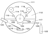
なお、酸化度を制御した酸化金属層を蒸着する技術はガスバリア性フィルムで開示されている(特許文献2)。しかし、この文献に記載のフィルムはガスバリアが目的の包装材料用フィルムであり、透明性が問われるため、蒸着膜厚が40nm以下と薄く、ポリエステルフィルムの膨張・収縮を抑制する効果が小さい。また、酸化度を制御して50nm以上の酸化金属層を蒸着するには、アルミニウムの蒸発量を増加する必要があり、それに合わせて酸素導入量も増やす必要がある。しかしながら、この文献に記載の方法では図3に示すような真空蒸着装置を用いるので厚膜化が困難である。すなわち、この真空蒸着装置111においては、真空チャンバ112の内部をポリエステルフィルムが巻出しロール部113から冷却ドラム116を経て巻取りロール部118へと走行する。このときに、るつぼ123内の金属材料119を電子銃120から照射した電子ビーム121で加熱蒸発させるとともに、酸素供給ノズル124から酸素ガスを導入し、蒸発した金属を酸化反応させながら冷却ドラム116上のポリエステルフィルムに蒸着する。しかしながら、酸素供給ノズル124が冷却ドラム116に近いため、酸素導入量を増やすとその酸素ガスの吹出流によって金属蒸気が飛ばされ、酸化度を制御することが難しい。また、金属と酸素が反応する空間が小さいこともあり、50nm以上といった金属酸化物の蒸着膜を形成することが難しく、形成された蒸着膜は不安定なものとなりやすい。そして不安定な蒸着膜は構造欠陥を多く生成させ寸法安定性の悪化を招く。さらに、これらのガスバリア性フィルムは包装材料用途であるため、ベースフィルムの厚みが10μm以上と厚く、また表面が平滑ではないため、容易に蒸着ができるのに対し、磁気記録媒体用支持体に用いられるポリエステルフィルムは一般的に厚みが薄く、平滑であるために、これらの方法のように工夫無く蒸着すると熱による変形などにより、蒸着中にフィルム破れが多発する。
本発明の目的は、上記の問題を解決し、寸法安定性に優れ、クラックしにくい磁気記録媒体用支持体を提供することにある。詳しくは、磁気記録媒体とした際に環境変化による寸法変化が少なく、クラック発生やエラーレートも少ない、走行耐久性に優れた高密度磁気記録媒体とすることができる支持体を提供することにある。 An object of the present invention is to solve the above-mentioned problems, and to provide a support for a magnetic recording medium that is excellent in dimensional stability and hardly cracks. More specifically, the present invention provides a support that can be used as a high-density magnetic recording medium excellent in running durability with little dimensional change due to environmental changes when the magnetic recording medium is used, and less cracking and error rate. .
上記課題を解決するための本発明は、次の(1)〜(5)を特徴とするものである。
(1)ポリエステルフィルムの両面に平均組成における酸素原子含有量が10at.%以上である金属系酸化物を含む層(M層)が設けられ、これらM層の厚みがそれぞれ50〜200nmである磁気記録媒体用支持体であって、該磁気記録媒体用支持体の全光線透過率が0〜75%であり、各表面の表面抵抗率が1×10²〜1×10¹³[Ω]であることを特徴とする磁気記録媒体用支持体。
(2)少なくとも一方の表面の中心線平均粗さRaが0.5〜10nmである、上記(1)に記載の磁気記録媒体用支持体。
(3)長手方向のヤング率が5〜13GPaである、上記(3)に記載の磁気記録媒体用支持体。
(4)前記ポリエステルフィルムの厚みが2〜6μmである、上記(1)〜(3)のいずれかに記載の磁気記録媒体用支持体。
(5) M層の金属元素濃度が10〜70at.%である、上記(1)〜(4)のいずれかに記載の磁気記録媒体用支持体。
(6) M層の金属結合している金属原子の存在比が1〜20at.%である、上記(1)〜(5)のいずれかに記載の磁気記録媒体用支持体。
(7) M層の金属系酸化物が酸化アルミニウムであり、水酸基と結合しているアルミニウム原子の存在比が0〜60at.%である、上記(1)〜(6)のいずれかに記載の磁気記録媒体用支持体。
(8)上記(1)〜(7)のいずれかに記載の磁気記録媒体用支持体の少なくとも片面に磁性層が設けられた磁気記録媒体。
The present invention for solving the above-described problems is characterized by the following (1) to (5).
(1) The oxygen atom content in the average composition is 10 at. % Of the metal-containing oxide layer (M layer), and the thickness of each of the M layers is 50 to 200 nm. A support for a magnetic recording medium having a light transmittance of 0 to 75% and a surface resistivity of each surface of 1 × 10 2 to 1 × 10 13 [Ω].
(2) The support for a magnetic recording medium according to (1), wherein the center line average roughness Ra of at least one surface is 0.5 to 10 nm.
(3) The support for a magnetic recording medium according to (3), wherein the Young's modulus in the longitudinal direction is 5 to 13 GPa.
(4) The support for a magnetic recording medium according to any one of (1) to (3), wherein the polyester film has a thickness of 2 to 6 μm.
(5) The metal element concentration of the M layer is 10 to 70 at. %, The support for a magnetic recording medium according to any one of the above (1) to (4).
(6) The abundance ratio of metal atoms in the M layer that are metal-bonded is 1 to 20 at. %, The magnetic recording medium support according to any one of (1) to (5) above.
(7) The metal oxide of the M layer is aluminum oxide, and the abundance ratio of aluminum atoms bonded to hydroxyl groups is 0 to 60 at. %, The magnetic recording medium support according to any one of (1) to (6) above.
(8) A magnetic recording medium in which a magnetic layer is provided on at least one side of the magnetic recording medium support according to any one of (1) to (7).
本発明の磁気記録媒体用支持体は、寸法安定性に優れクラックも発生しにくい支持体であって、特に磁気記録媒体とした際に環境変化による寸法変化が小さく、クラック発生、エラーレートが少ない高密度磁気記録媒体とすることができる支持体を得ることができる。 The support for a magnetic recording medium of the present invention is a support that has excellent dimensional stability and is less likely to generate cracks. Particularly, when used as a magnetic recording medium, the dimensional change due to environmental changes is small, crack generation, and error rate are low. A support that can be used as a high-density magnetic recording medium can be obtained.
本発明の磁気記録媒体用支持体は、ポリエステルフィルムの両方の表面上に金属系酸化物を含む層(M層)が形成されてなる。金属系酸化物とは、例えば、Cu、Zn、Al、Si、Fe、Ag、Ti、Mg、Sn、Zr、In、Cr、Mn、V、Ni、Mo、Ce、Ga、Hf、Nb、Ta、Y、Wなどの金属成分を酸化させたものであって、組成分析を行った場合の平均組成における酸素原子含有量が10at.%以上となっているものをいう。なお、at.%とは、atomic%の略であり、atomic%とは原子数100個当たりの該原子数の個数を示したものである。 The support for a magnetic recording medium of the present invention is formed by forming a layer (M layer) containing a metal-based oxide on both surfaces of a polyester film. Examples of the metal oxide include Cu, Zn, Al, Si, Fe, Ag, Ti, Mg, Sn, Zr, In, Cr, Mn, V, Ni, Mo, Ce, Ga, Hf, Nb, and Ta. , Y, W, and the like, and the oxygen atom content in the average composition when the composition analysis is performed is 10 at. The thing which is more than%. At. “%” Is an abbreviation of “atomic%”, and “atomic%” indicates the number of atoms per 100 atoms.
上記の金属系酸化物は、全光線透過率や表面抵抗率が後述するような範囲内であれば両表面で異なる金属成分を含んでいても良く、また、複数種の金属成分を混合して含んでいても構わないが、より好ましくは両表面で同一種の金属成分を含む方が良い。中でも、金属系酸化物は、酸化度の制御性、寸法安定性、生産性、環境性の観点から、アルミニウム、銅、亜鉛、銀、珪素元素の少なくとも一種を含んでいることが好ましく、より好ましくはアルミニウム元素が主成分となっていることが好ましい。 The above metal-based oxide may contain different metal components on both surfaces as long as the total light transmittance and surface resistivity are within the ranges described later, and a plurality of types of metal components may be mixed. It may be included, but it is more preferable that both surfaces contain the same type of metal component. Among these, the metal-based oxide preferably contains at least one of aluminum, copper, zinc, silver, and silicon elements from the viewpoints of controllability of the degree of oxidation, dimensional stability, productivity, and environmental properties, and more preferably. Is preferably composed mainly of an aluminum element.
M層の金属元素濃度は10〜70at.%であることが好ましい。金属元素濃度が10at.%より少ないと、金属原子に対して酸素原子が多すぎるため、不完全な構造(金属原子や酸素原子が未結合で存在する)を取りやすく、補強する効果が小さくなり寸法安定性が低下してしまう。70at.%より多い場合、ほぼ金属の特性を持つため、導電性によるショートの問題や強度が低く寸法安定性が低いなどの問題がある。より好ましくは20〜60at.%であり、さらに好ましくは30〜50at.%である。金属元素濃度は金属蒸発量と酸素ガス導入量から制御することができる。金属元素濃度を小さくするには、金属蒸発量を少なくし、酸素ガス導入量を多くすればよく、金属元素濃度を大きくするにはその逆にすればよい。 The metal element concentration of the M layer is 10 to 70 at. % Is preferred. Metal element concentration is 10 at. If it is less than%, there are too many oxygen atoms relative to the metal atoms, so an incomplete structure (metal atoms or oxygen atoms are present in an unbonded state) is likely to be obtained, and the effect of reinforcement is reduced, reducing dimensional stability. End up. 70 at. If it exceeds 50%, it has almost metal characteristics, so there are problems such as short-circuit due to conductivity and low strength and low dimensional stability. More preferably 20 to 60 at. %, And more preferably 30 to 50 at. %. The metal element concentration can be controlled from the metal evaporation amount and the oxygen gas introduction amount. In order to reduce the metal element concentration, it is only necessary to reduce the amount of metal evaporation and increase the amount of oxygen gas introduced, and in order to increase the metal element concentration, the opposite is necessary.
また、M層の金属結合している金属原子の存在比は1〜20at.%であることが好ましい。金属結合の存在比が1at.%より小さいと、たとえ上述するような金属元素濃度であっても靭性のある金属結合が少ないためクラックが起こりやすい。20at.%より大きいと、たとえ上述するような金属元素濃度であっても金属の特性を持つため導電性によるショートの問題が起こりやすくなる。金属結合している金属原子は吸湿しないため、構造欠陥を作りにくく寸法安定性の悪化を防ぐことができる。より好ましくは2〜15at.%、さらに好ましくは3〜10at.%である。金属結合の存在比は金属の蒸発量と酸素ガス導入量から制御することができるが金属元素濃度よりもさらにミクロな構造を示した組成であり、酸化反応の制御が重要となる。金属結合の存在比は金属と酸素ガスの反応効率が影響するため、酸素ガス導入の方法が重要となる。酸素ガス導入方法は蒸着源の真横から金属蒸気の流れる方向と同じ方向に供給することが好ましい。これは、金属蒸気と酸素ガスの反応が促進され、酸化反応が完了した状態でポリエステルフィルムに到達するため、過剰な酸素ガスを取り込んで金属結合存在比が小さくなったり、酸素ガスと反応できずに金属原子同士が結合し、金属結合存在比が大きくなってしまったりすることがなくなる。また、金属蒸気や酸素ガスを高エネルギー化することで反応が促進されるため、電子ビーム蒸着法により金属蒸気を高エネルギー化し、プラズマ処理などで酸素ガスを高エネルギー化することが好ましい。 The abundance ratio of metal atoms in the M layer that are metal-bonded is 1 to 20 at. % Is preferred. The abundance ratio of metal bonds is 1 at. If it is smaller than%, cracks are likely to occur because there are few tough metal bonds even at the metal element concentrations as described above. 20 at. If it is larger than%, even if the metal element concentration is as described above, the problem of short-circuiting due to conductivity is likely to occur because of the metal characteristics. Since metal atoms that are metal-bonded do not absorb moisture, it is difficult to form structural defects, and deterioration of dimensional stability can be prevented. More preferably 2 to 15 at. %, More preferably 3 to 10 at. %. The abundance ratio of the metal bond can be controlled from the amount of evaporation of the metal and the amount of oxygen gas introduced, but it is a composition that shows a more micro structure than the metal element concentration, and the control of the oxidation reaction is important. Since the abundance ratio of metal bonds is influenced by the reaction efficiency between the metal and oxygen gas, the method of introducing oxygen gas is important. The oxygen gas introduction method is preferably supplied in the same direction as the flow direction of the metal vapor from the side of the vapor deposition source. This is because the reaction between the metal vapor and the oxygen gas is promoted and reaches the polyester film in a state where the oxidation reaction is completed, so the excess oxygen gas is taken in and the metal bond abundance ratio becomes small, or it cannot react with the oxygen gas. The metal atoms are not bonded to each other and the metal bond abundance ratio is not increased. Further, since the reaction is promoted by increasing the energy of the metal vapor or oxygen gas, it is preferable to increase the energy of the metal vapor by electron beam evaporation and increase the energy of the oxygen gas by plasma treatment or the like.
M層の金属成分は上述にあるようにアルミニウム元素が好ましく、M層は酸化アルミニウムであることが好ましい。さらに酸化アルミニウム中のアルミニウムの結合状態は、水酸基と結合しているアルミニウム原子の存在比が0〜60at.%であることが好ましい。一般的に酸化アルミニウムは水蒸気を吸湿して水和物(Al(OH)3)を形成する。本願では水和物も酸化アルミニウムとして考える。水酸基と結合しているとはアルミニウム原子が吸湿して水和物になっていることを表し、光電子分光法(XPS)にてアルミニウムの結合状態を分析することで存在比を測定することができる。水和物の形成により部分的に体積変化が起こりM層内にひずみができ構造欠陥が発生する。水和物形成は寸法安定性を悪化させる要因となるため、60at.%以下であることが好ましい。より好ましくは50at.%以下、さらに好ましくは40at.%以下である。水酸基と結合しているアルミニウム原子の存在比を小さくさせるには、水和物を形成させないこと、すなわち水分を吸湿させないことが好ましい。アルミニウム原子と酸素原子がしっかり結合していて、未結合のアルミニウム原子や酸素原子を減らし、不完全な構造をなくすように形成することで水分の吸湿を防ぐことができる。不完全な構造はないことが好ましいが、形成時に生成してしまった場合は強制的に一気に吸湿させ、M層全体から未結合のアルミニウムや酸素原子をなくすことが好ましい。つまり、M層形成後は未結合原子をなくすための強制加湿処理を行うことが好ましい。加湿処理を行わず、未結合原子が残存していると、部分的に吸湿が起こり、その吸湿による体積変化などでM層に構造欠陥を作りやすくなる。構造欠陥はさらなる吸湿を発生させる原因ともなり、加湿処理を行わない場合より、水酸基と結合しているアルミニウム原子の存在比が高くなってしまう場合もある。 The metal component of the M layer is preferably an aluminum element as described above, and the M layer is preferably aluminum oxide. Furthermore, the bonding state of aluminum in aluminum oxide is such that the abundance ratio of aluminum atoms bonded to hydroxyl groups is 0 to 60 at. % Is preferred. In general, aluminum oxide absorbs water vapor to form a hydrate (Al (OH) 3 ). In this application, the hydrate is also considered as aluminum oxide. Bonding with a hydroxyl group means that the aluminum atom absorbs moisture to form a hydrate, and the abundance ratio can be measured by analyzing the bonding state of aluminum by photoelectron spectroscopy (XPS). . Due to the formation of the hydrate, a volume change occurs partially and the M layer is distorted and a structural defect is generated. Since hydrate formation causes deterioration in dimensional stability, 60 at. % Or less is preferable. More preferably, 50 at. % Or less, more preferably 40 at. % Or less. In order to reduce the abundance ratio of the aluminum atom bonded to the hydroxyl group, it is preferable not to form a hydrate, that is, not to absorb moisture. Moisture absorption can be prevented by forming aluminum atoms and oxygen atoms so that unbonded aluminum atoms and oxygen atoms are reduced and an incomplete structure is eliminated. It is preferable that there is no incomplete structure, but if it is formed at the time of formation, it is preferable to forcibly absorb moisture all at once and to remove unbonded aluminum and oxygen atoms from the entire M layer. That is, after the M layer is formed, it is preferable to perform a forced humidification process for eliminating unbonded atoms. If the unbonded atoms remain without performing the humidification process, partial moisture absorption occurs, and it becomes easy to create a structural defect in the M layer due to a volume change due to the moisture absorption. The structural defect may cause further moisture absorption, and the abundance ratio of aluminum atoms bonded to the hydroxyl group may be higher than when no humidification treatment is performed.
また、M層を形成する時にポリエステルフィルムが吸湿していると、形成時の熱負荷などによりポリエステルフィルムから水分が放出され、M層の中に水分を取り込むこととなり、水和物を形成してしまうことがある。M層を形成する前にポリエステルフィルム内の水分量を減らしておくことが好ましい。 In addition, if the polyester film absorbs moisture when forming the M layer, moisture is released from the polyester film due to heat load during formation, and moisture is taken into the M layer, forming a hydrate. It may end up. It is preferable to reduce the water content in the polyester film before forming the M layer.
M層の厚みは、それぞれ50〜200nmである必要がある。M層の厚みが50nmより小さい場合、補強効果が小さく、寸法安定性が改善されない。M層の厚みの下限は、好ましくは60nm、より好ましくは70nmである。一方、M層の厚みが200nmより大きい場合は、クラックを生じやすく寸法安定性が悪化しやすい。また走行を繰り返すことで剥離や脱落が発生し易く、結果として寸法安定性が悪化する傾向にある。また、全光線透過率や表面抵抗率を本発明の範囲内にするには酸素の導入量を増やす必要があるが、真空製膜装置を使って200nm以上の厚みのM層を形成しようとすると、真空度が低下してしまい金属蒸気が蒸発しにくく不安定になる。その結果、M層が不完全な構造になり、寸法安定性、走行耐久性の悪い磁気記録媒体となってしまう。また、スパッタ法では酸素導入量が多いとターゲットの表面を酸化させてしまい、スパッタによる金属原子の飛び出しが不安定となる。その結果、真空蒸着法と同様、不完全な構造になってしまい、寸法安定性、走行耐久性の悪い磁気記録媒体となってしまう。M層の厚みの上限は、好ましくは180nm、より好ましくは150nmである。好ましい範囲としては、60〜180nm、より好ましい範囲としては、70〜150nmである。 Each of the M layers needs to have a thickness of 50 to 200 nm. When the thickness of the M layer is smaller than 50 nm, the reinforcing effect is small and the dimensional stability is not improved. The lower limit of the thickness of the M layer is preferably 60 nm, more preferably 70 nm. On the other hand, if the thickness of the M layer is greater than 200 nm, cracks are likely to occur and dimensional stability is likely to deteriorate. Further, repeated running tends to cause peeling and dropping, and as a result, dimensional stability tends to deteriorate. In order to make the total light transmittance and surface resistivity within the range of the present invention, it is necessary to increase the amount of oxygen introduced. However, when an M layer having a thickness of 200 nm or more is to be formed using a vacuum film forming apparatus. The degree of vacuum is lowered and the metal vapor is difficult to evaporate and becomes unstable. As a result, the M layer has an incomplete structure, resulting in a magnetic recording medium having poor dimensional stability and running durability. Further, in the sputtering method, if the amount of oxygen introduced is large, the surface of the target is oxidized, and the jumping out of metal atoms by sputtering becomes unstable. As a result, like the vacuum deposition method, the structure becomes incomplete, resulting in a magnetic recording medium with poor dimensional stability and running durability. The upper limit of the thickness of the M layer is preferably 180 nm, more preferably 150 nm. A preferable range is 60 to 180 nm, and a more preferable range is 70 to 150 nm.
本発明の磁気記録媒体用支持体は、全光線透過率が0〜75%である必要がある。75%より高い場合、酸化が進みすぎているため、M層が硬く脆くなり、張力や湾曲によってクラックを生じやすく、また、酸化物の吸湿膨張が起こり易く寸法安定性が劣る傾向にある。全光線透過の下限は、より好ましくは1%であり、さらに好ましくは5%である。一方、上限は70%が好ましく、さらに好ましくは65%である。なお、本発明の支持体としては全光線透過率が0%のものも包含される。これは、支持体が、上記したような金属成分を少しだけ酸化させた金属系酸化物を含む層を有する場合、表面抵抗率が後述するような範囲になるものの、全光線透過率が0%、すなわち、検出限界以下という場合があるからである。より好ましい範囲としては、1〜70%、より好ましい範囲としては、5〜65%である。 The support for a magnetic recording medium of the present invention needs to have a total light transmittance of 0 to 75%. If it is higher than 75%, the oxidation has progressed too much, so the M layer becomes hard and brittle, and cracks are likely to occur due to tension and curvature, and the hygroscopic expansion of the oxide tends to occur and the dimensional stability tends to be poor. The lower limit of the total light transmission is more preferably 1%, still more preferably 5%. On the other hand, the upper limit is preferably 70%, more preferably 65%. The support of the present invention includes those having a total light transmittance of 0%. This is because, when the support has a layer containing a metal-based oxide obtained by slightly oxidizing the metal component as described above, the surface resistivity is in the range described later, but the total light transmittance is 0%. That is, it may be below the detection limit. A more preferable range is 1 to 70%, and a more preferable range is 5 to 65%.
本発明の磁気記録媒体用支持体は、表面抵抗率が1×102〜1×1013Ωであり、好ましくは1.0×102〜9.9×1012Ωである。表面抵抗率とは、表面比抵抗(Ω/□)とも表記される特性値であり、純粋な表面抵抗(面積によって変わる抵抗値)や線抵抗(導線などの抵抗)とは異なるものである。表面抵抗率が1.0×102Ωより低い場合、導電性が高すぎるため、静電気や漏れ電流によって磁気テープに電流が流れてしまい、その電流のために磁気ヘッドがショートし故障する危険性がある。表面抵抗率の下限は、好ましくは1.0×104Ωであり、より好ましくは1.0×105Ωである。一方、表面抵抗率が1×1013Ω、特に9.9×1012Ωより高い場合、透過率が高い場合と同様に酸化が進みすぎているために、クラックの発生や寸法安定性の悪化の傾向がある。表面抵抗率の上限は、好ましくは9.9×1011Ω、より好ましくは9.9×1010Ωである。好ましい範囲としては、1.0×104〜9.9×1011Ω、より好ましい範囲としては、1.0×105〜9.9×1010Ωである。なお、磁性層を設ける側の表面(A)と磁性層を設けない側の表面、すなわちバックコート層側の表面(B)とでは、表面抵抗率の値が同じでもよいが、バックコート層側の表面(B)の表面抵抗率が低い方が好ましい。 The support for a magnetic recording medium of the present invention has a surface resistivity of 1 × 10 2 to 1 × 10 13 Ω, preferably 1.0 × 10 2 to 9.9 × 10 12 Ω. The surface resistivity is a characteristic value also expressed as a surface specific resistance (Ω / □), and is different from a pure surface resistance (resistance value that varies depending on the area) and line resistance (resistance such as a conducting wire). If the surface resistivity is lower than 1.0 × 10 2 Ω, the electrical conductivity is too high, so that the current flows in the magnetic tape due to static electricity or leakage current, and the risk of the magnetic head shorting and failure due to the current. There is. The lower limit of the surface resistivity is preferably 1.0 × 10 4 Ω, more preferably 1.0 × 10 5 Ω. On the other hand, if the surface resistivity is higher than 1 × 10 13 Ω, especially 9.9 × 10 12 Ω, the oxidation has progressed too much as in the case of high transmittance. There is a tendency. The upper limit of the surface resistivity is preferably 9.9 × 10 11 Ω, more preferably 9.9 × 10 10 Ω. A preferable range is 1.0 × 10 4 to 9.9 × 10 11 Ω, and a more preferable range is 1.0 × 10 5 to 9.9 × 10 10 Ω. Note that the surface resistivity value may be the same on the surface (A) on the side where the magnetic layer is provided and the surface on the side where the magnetic layer is not provided, that is, the surface (B) on the backcoat layer side. It is preferable that the surface resistivity of the surface (B) is lower.
そして、本発明の磁気記録媒体用支持体において、磁性層を設ける側の表面(A)の中心線平均粗さRaが0.5nm〜10nmであることが好ましい。磁性層を設ける側の表面(A)のRaが0.5nmより小さい場合は、フィルム製造、加工工程などで、搬送ロールなどとの摩擦係数が大きくなり、工程トラブルを起こすことがあり、磁気テープとして用いる場合に、磁気ヘッドとの摩擦が大きくなり、磁気テープ特性が低下しやすい。また、Raが10nmより大きい場合は、高密度記録の磁気テープとして用いる場合に、電磁変換特性が低下することがある。磁性層を設ける側の表面(A)のRaの下限は、より好ましくは2nm、さらに好ましくは3nmであり、上限は9nm、さらに好ましくは8nmである。より好ましい範囲としては、2〜9nm、さらに好ましい範囲としては、3〜8nmである。 In the support for a magnetic recording medium of the present invention, the center line average roughness Ra of the surface (A) on the side where the magnetic layer is provided is preferably 0.5 nm to 10 nm. If Ra on the surface (A) on the side where the magnetic layer is provided is smaller than 0.5 nm, the friction coefficient with the transport roll, etc. may increase during film production, processing, etc., which may cause process troubles. When used as a magnetic head, the friction with the magnetic head increases and the magnetic tape characteristics tend to deteriorate. When Ra is larger than 10 nm, electromagnetic conversion characteristics may be deteriorated when used as a magnetic tape for high-density recording. The lower limit of Ra on the surface (A) on the side where the magnetic layer is provided is more preferably 2 nm, still more preferably 3 nm, and the upper limit is 9 nm, more preferably 8 nm. A more preferable range is 2 to 9 nm, and a further preferable range is 3 to 8 nm.
一方、バックコート層側の表面(B)の中心線平均粗さRaは3〜30nmであることが好ましい。バックコート層側の表面(B)のRaが3nmより小さい場合は、フィルム製造、加工工程などで、搬送ロールなどとの摩擦係数が大きくなり、工程トラブルを起こすことがあり、磁気テープとして用いる場合に、ガイドロールとの摩擦が大きくなり、テープ走行性が低下することがある。また、Raが30nmより大きい場合は、フィルムロールやパンケーキとして保管する際に、表面突起が反対側の表面に転写し、電磁変換特性が低下する傾向がある。バックコート層側の表面(B)のRaの下限は、より好ましくは5nm、さらに好ましくは7nmであり、上限は20nm、さらに好ましくは15nmである。より好ましい範囲としては、5〜20nm、さらに好ましい範囲としては7〜15nmである。 On the other hand, the center line average roughness Ra of the surface (B) on the back coat layer side is preferably 3 to 30 nm. When Ra on the surface (B) on the backcoat layer side is smaller than 3 nm, the friction coefficient with the transport rolls, etc. may increase in film production and processing processes, etc., which may cause process troubles. When used as a magnetic tape In addition, the friction with the guide roll is increased, and the tape running property may be lowered. On the other hand, when Ra is larger than 30 nm, when stored as a film roll or pancake, the surface protrusion tends to be transferred to the surface on the opposite side, and the electromagnetic conversion characteristics tend to deteriorate. The lower limit of Ra on the surface (B) on the backcoat layer side is more preferably 5 nm, still more preferably 7 nm, and the upper limit is 20 nm, more preferably 15 nm. A more preferable range is 5 to 20 nm, and a further preferable range is 7 to 15 nm.
本発明の磁気記録媒体用支持体は、幅方向の湿度膨張係数が−3〜10ppm/%RHであることも好ましい。湿度膨張係数が上記範囲内であることは、磁気記録媒体への加工工程や磁気記録媒体の記録再生時の高湿条件での寸法安定性の観点から好ましい。幅方向の湿度膨張係数の上限は、より好ましくは8ppm/%RH、さらに好ましくは7ppm/%RHである。幅方向の湿度膨張係数の下限はより好ましくは−1ppm/%RH、さらに好ましくは0ppm/%RHである。より好ましい範囲としては、−1〜8ppm/%RH、さらに好ましい範囲としては0〜7ppm/%RHである。 The magnetic recording medium support of the present invention preferably has a humidity expansion coefficient in the width direction of -3 to 10 ppm /% RH. It is preferable that the humidity expansion coefficient is in the above range from the viewpoint of dimensional stability under high humidity conditions during processing of the magnetic recording medium and recording / reproduction of the magnetic recording medium. The upper limit of the humidity expansion coefficient in the width direction is more preferably 8 ppm /% RH, and even more preferably 7 ppm /% RH. The lower limit of the humidity expansion coefficient in the width direction is more preferably -1 ppm /% RH, and still more preferably 0 ppm /% RH. A more preferable range is -1 to 8 ppm /% RH, and a further preferable range is 0 to 7 ppm /% RH.
本発明の磁気記録媒体用支持体は、長手方向のヤング率が5〜13GPaであることが好ましい。長手方向のヤング率が5GPaより小さい場合、テープドライブ内での長手方向への張力によって長手方向に伸び、この伸び変形により幅方向に収縮し、記録トラックずれという問題が発生しやすい。長手方向のヤング率の下限は、より好ましくは6GPa、さらに好ましくは7GPaである。一方、長手方向のヤング率が13GPaより大きい場合、幅方向のヤング率を好ましい範囲に制御することが難しくなり、幅方向のヤング率が不足し、エッジダメージの原因となる。長手方向のヤング率の上限は、より好ましくは12GPa、さらに好ましくは11GPaである。より好ましい範囲としては、6〜12GPa、さらに好ましい範囲としては7〜11GPaである。 The magnetic recording medium support of the present invention preferably has a Young's modulus in the longitudinal direction of 5 to 13 GPa. When the Young's modulus in the longitudinal direction is smaller than 5 GPa, the film stretches in the longitudinal direction due to the tension in the longitudinal direction in the tape drive, and contracts in the width direction due to the elongation deformation, so that a problem of recording track deviation is likely to occur. The lower limit of the Young's modulus in the longitudinal direction is more preferably 6 GPa, still more preferably 7 GPa. On the other hand, when the Young's modulus in the longitudinal direction is larger than 13 GPa, it becomes difficult to control the Young's modulus in the width direction within a preferable range, and the Young's modulus in the width direction becomes insufficient, causing edge damage. The upper limit of the Young's modulus in the longitudinal direction is more preferably 12 GPa, still more preferably 11 GPa. A more preferable range is 6 to 12 GPa, and a further preferable range is 7 to 11 GPa.
本発明の磁気記録媒体用支持体は、幅方向のヤング率が5〜13GPaの範囲であることが好ましい。幅方向のヤング率が5GPaより小さい場合、エッジダメージの原因となったりすることがある。幅方向のヤング率の下限は、より好ましくは6GPa、さらに好ましくは7GPaである。一方、幅方向のヤング率が13GPaより大きい場合、長手方向のヤング率を好ましい範囲に制御することが難しくなり長手方向の張力により変形しやすくなったり、スリット性が悪化することがある。幅方向のヤング率の上限は、より好ましくは12GPa、さらに好ましくは11GPaである。より好ましい範囲としては、6〜12GPa、さらに好ましい範囲としては7〜11GPaである。 The support for a magnetic recording medium of the present invention preferably has a Young's modulus in the width direction in the range of 5 to 13 GPa. If the Young's modulus in the width direction is less than 5 GPa, edge damage may be caused. The lower limit of the Young's modulus in the width direction is more preferably 6 GPa, and even more preferably 7 GPa. On the other hand, when the Young's modulus in the width direction is larger than 13 GPa, it is difficult to control the Young's modulus in the longitudinal direction within a preferable range, and it may be easily deformed by the tension in the longitudinal direction, or the slit property may be deteriorated. The upper limit of the Young's modulus in the width direction is more preferably 12 GPa, still more preferably 11 GPa. A more preferable range is 6 to 12 GPa, and a further preferable range is 7 to 11 GPa.
なお、本発明において、支持体の長手方向とは、一般的にMD方向といわれる方向であって、ポリエステルフィルム製造工程時の長手方向と同じ方向を指し、支持体の幅方向とは、一般的にTD方向といわれる方向であって、ポリエステルフィルム製造工程時の幅方向と同じ方向を指す。 In addition, in this invention, the longitudinal direction of a support body is a direction generally called MD direction, Comprising: The same direction as the longitudinal direction at the time of a polyester film manufacturing process is pointed out, and the width direction of a support body is general It is a direction called TD direction, and refers to the same direction as the width direction during the polyester film manufacturing process.
本発明において、ポリエステルフィルムとは、例えば、芳香族ジカルボン酸、脂環族ジカルボン酸または脂肪族ジカルボン酸などの酸成分やジオール成分を構成単位(重合単位)とするポリマーで構成されたものである。 In the present invention, the polyester film is composed of, for example, a polymer having an acid component or a diol component such as aromatic dicarboxylic acid, alicyclic dicarboxylic acid or aliphatic dicarboxylic acid as a structural unit (polymerization unit). .
芳香族ジカルボン酸成分としては、例えば、テレフタル酸、イソフタル酸、フタル酸、1,4−ナフタレンジカルボン酸、1,5−ナフタレンジカルボン酸、2,6−ナフタレンジカルボン酸、4,4’−ジフェニルジカルボン酸、4,4’−ジフェニルエーテルジカルボン酸、4,4’−ジフェニルスルホンジカルボン酸等を用いることができ、なかでも好ましくは、テレフタル酸、フタル酸、2,6−ナフタレンジカルボン酸を用いることができる。脂環族ジカルボン酸成分としては、例えば、シクロヘキサンジカルボン酸等を用いることができる。脂肪族ジカルボン酸成分としては、例えば、アジピン酸、スベリン酸、セバシン酸、ドデカンジオン酸等を用いることができる。これらの酸成分は一種のみを用いてもよく、二種以上を併用してもよい。 Examples of the aromatic dicarboxylic acid component include terephthalic acid, isophthalic acid, phthalic acid, 1,4-naphthalenedicarboxylic acid, 1,5-naphthalenedicarboxylic acid, 2,6-naphthalenedicarboxylic acid, and 4,4′-diphenyldicarboxylic acid. Acid, 4,4′-diphenyl ether dicarboxylic acid, 4,4′-diphenylsulfone dicarboxylic acid, and the like can be used. Among them, terephthalic acid, phthalic acid, and 2,6-naphthalenedicarboxylic acid can be preferably used. . As the alicyclic dicarboxylic acid component, for example, cyclohexane dicarboxylic acid or the like can be used. As the aliphatic dicarboxylic acid component, for example, adipic acid, suberic acid, sebacic acid, dodecanedioic acid and the like can be used. These acid components may be used alone or in combination of two or more.
ジオール成分としては、例えば、エチレングリコール、1,2−プロパンジオール、1,3−プロパンジオール、ネオペンチルグリコール、1,3−ブタンジオール、1,4−ブタンジオール、1,5−ペンタンジオール、1,6−ヘキサンジオール、1,2−シクロヘキサンジメタノール、1,3−シクロヘキサンジメタノール、1,4−シクロヘキサンジメタノール、ジエチレングリコール、トリエチレングリコール、ポリアルキレングリコール、2,2’−ビス(4’−β−ヒドロキシエトキシフェニル)プロパン等を用いることができ、なかでも、エチレングリコール、1,4−ブタンジオール、1,4−シクロヘキサンジメタノール、ジエチレングリコール等を好ましく用いることができ、特に好ましくは、エチレングリコール等を用いることができる。これらのジオール成分は一種のみを用いてもよく、二種以上を併用してもよい。 Examples of the diol component include ethylene glycol, 1,2-propanediol, 1,3-propanediol, neopentyl glycol, 1,3-butanediol, 1,4-butanediol, 1,5-pentanediol, , 6-hexanediol, 1,2-cyclohexanedimethanol, 1,3-cyclohexanedimethanol, 1,4-cyclohexanedimethanol, diethylene glycol, triethylene glycol, polyalkylene glycol, 2,2'-bis (4'- β-hydroxyethoxyphenyl) propane and the like can be used, and among them, ethylene glycol, 1,4-butanediol, 1,4-cyclohexanedimethanol, diethylene glycol and the like can be preferably used, and ethylene glycol is particularly preferable. etc It can be used. These diol components may be used alone or in combination of two or more.
ポリエステルには、ラウリルアルコール、イソシアン酸フェニル等の単官能化合物が共重合されていてもよいし、トリメリット酸、ピロメリット酸、グリセロール、ペンタエリスリトール、2,4−ジオキシ安息香酸、等の3官能化合物などが、過度に分枝や架橋をせずポリマーが実質的に線状である範囲内で共重合されていてもよい。さらに酸成分、ジオール成分以外に、p−ヒドロキシ安息香酸、m−ヒドロキシ安息香酸、2,6−ヒドロキシナフトエ酸などの芳香族ヒドロキシカルボン酸およびp−アミノフェノール、p−アミノ安息香酸などを本発明の効果が損なわれない程度の少量であればさらに共重合せしめることができる。 The polyester may be copolymerized with a monofunctional compound such as lauryl alcohol or phenyl isocyanate, or a trifunctional compound such as trimellitic acid, pyromellitic acid, glycerol, pentaerythritol, or 2,4-dioxybenzoic acid. A compound or the like may be copolymerized within a range in which the polymer is substantially linear without excessive branching or crosslinking. In addition to the acid component and diol component, the present invention includes aromatic hydroxycarboxylic acids such as p-hydroxybenzoic acid, m-hydroxybenzoic acid, and 2,6-hydroxynaphthoic acid, p-aminophenol, and p-aminobenzoic acid. As long as the effect is not impaired, the copolymerization can be further carried out.
ポリエステルとしては、ポリエチレンテレフタレート、ポリエチレンナフタレートが好ましい。また、これらの共重合体、および変性体でもよく、他の熱可塑性樹脂とのポリマーアロイでも良い。ここでいうポリマーアロイとは高分子多成分系のことであり、共重合によるブロックコポリマーであってもよいし、混合などによるポリマーブレンドでも良い。特に、上記ポリエステル樹脂とポリイミド系樹脂のポリマーアロイは混合割合によって耐熱性(ガラス転移温度)を制御できるため、使用条件に合わせたポリマー設計ができるため好ましい。ポリマーの混合割合はNMR法(核磁気共鳴法)や顕微FT−IR法(フーリエ変換顕微赤外分光法)を用いて調べることができる。 Polyester is preferably polyethylene terephthalate or polyethylene naphthalate. Further, these copolymers and modified products may be used, and polymer alloys with other thermoplastic resins may be used. The polymer alloy here is a polymer multi-component system, and may be a block copolymer by copolymerization or a polymer blend by mixing. In particular, the polymer alloy of the polyester resin and the polyimide resin is preferable because the heat resistance (glass transition temperature) can be controlled by the mixing ratio, and the polymer can be designed according to the use conditions. The mixing ratio of the polymer can be examined using NMR method (nuclear magnetic resonance method) or microscopic FT-IR method (Fourier transform microinfrared spectroscopy).
ポリイミド系樹脂としては、例えば、下記一般式で示されるような構造単位を含有するものが好ましい。 As a polyimide-type resin, what contains a structural unit as shown by the following general formula, for example is preferable.

ただし、式中のR1は、 However, R 1 in the formula is
などの脂肪族炭化水素基、脂環族炭化水素基、芳香族炭化水素基から選ばれた一種もしくは二種以上の基を表している。また、式中のR2は、 Represents one or two or more groups selected from an aliphatic hydrocarbon group, an alicyclic hydrocarbon group, and an aromatic hydrocarbon group. R 2 in the formula is
などの脂肪族炭化水素基、脂環族炭化水素基、芳香族炭化水素基から選ばれた一種もしくは二種以上の基を表している。 Represents one or two or more groups selected from an aliphatic hydrocarbon group, an alicyclic hydrocarbon group, and an aromatic hydrocarbon group.
溶融成形性やポリエステルとの親和性などの点から、下記一般式で示されるような、ポリイミド構成成分にエーテル結合を含有するポリエーテルイミドが特に好ましい。 From the viewpoints of melt moldability and affinity with polyester, a polyetherimide containing an ether bond in the polyimide component as shown by the following general formula is particularly preferred.
(ただし、上記式中R3は、6〜30個の炭素原子を有する2価の芳香族または脂肪族残基、R4は6〜30個の炭素原子を有する2価の芳香族残基、2〜20個の炭素原子を有するアルキレン基、2〜20個の炭素原子を有するシクロアルキレン基、および2〜8個の炭素原子を有するアルキレン基で連鎖停止されたポリジオルガノシロキサン基からなる群より選択された2価の有機基である。)
上記R3、R4としては、例えば、下記式群に示される芳香族残基を挙げることができる。
(Wherein R 3 is a divalent aromatic or aliphatic residue having 6 to 30 carbon atoms, R 4 is a divalent aromatic residue having 6 to 30 carbon atoms, From the group consisting of alkylene groups having 2 to 20 carbon atoms, cycloalkylene groups having 2 to 20 carbon atoms, and polydiorganosiloxane groups chain-terminated with alkylene groups having 2 to 8 carbon atoms Selected divalent organic group.)
Examples of R 3 and R 4 include aromatic residues represented by the following formula group.
本発明では、ポリエステルとの親和性、コスト、溶融成形性等の観点から、2,2−ビス[4−(2,3−ジカルボキシフェノキシ)フェニル]プロパン二無水物とm−フェニレンジアミン、またはp−フェニレンジアミンとの縮合物である、下記式で示される繰り返し単位を有するポリマーが好ましい In the present invention, 2,2-bis [4- (2,3-dicarboxyphenoxy) phenyl] propane dianhydride and m-phenylenediamine from the viewpoint of affinity with polyester, cost, melt moldability, and the like, or A polymer having a repeating unit represented by the following formula, which is a condensate with p-phenylenediamine, is preferable.
または Or
(nは2以上の整数、好ましくは20〜50の整数)
このポリエーテルイミドは、“ウルテム”(登録商標)の商品名で、ジーイープラスチックス社より入手可能である。
(N is an integer of 2 or more, preferably an integer of 20 to 50)
This polyetherimide is available from GE Plastics under the trade name “Ultem” (registered trademark).
本発明において、ポリエステルフィルムは2層以上の積層構成であることが好ましい。特に、本発明の支持体は、磁気記録媒体に用いるため、一方の表面には、優れた電磁変換特性を得るための平滑さが求められ、他方の表面には、製膜・加工工程での搬送や、磁気テープの走行性や走行耐久性を付与するための粗さが求められる。そのため、ポリエステルフィルムを2層以上の積層構成にすることが好ましい。 In the present invention, the polyester film preferably has a laminated structure of two or more layers. In particular, since the support of the present invention is used for a magnetic recording medium, one surface is required to have smoothness for obtaining excellent electromagnetic conversion characteristics, and the other surface is subjected to film formation / processing steps. Roughness is required for imparting transportability and running durability of the magnetic tape. Therefore, it is preferable that the polyester film has a laminated structure of two or more layers.
ポリエステルフィルムには、その表面に易滑性や耐摩耗性、耐スクラッチ性などを付与するため、無機粒子、有機粒子、例えば、クレー、マイカ、酸化チタン、炭酸カルシウム、カリオン、タルク、湿式シリカ、乾式シリカ、コロイド状シリカ、リン酸カルシウム、硫酸バリウム、アルミナ、ジルコニア等の無機粒子、アクリル酸類、スチレン系樹脂、熱硬化樹脂、シリコーン、イミド系化合物等を構成成分とする有機粒子、ポリエステル重合反応時に添加する触媒等によって析出する粒子(いわゆる内部粒子)などが添加されていてもよい。粒子の粒径はTEMなどによって調べることができ、粒子の添加量はX線マイクロアナライザーや熱分解ガスクロマト質量分析などによって調べることができる。 The polyester film is provided with inorganic and organic particles such as clay, mica, titanium oxide, calcium carbonate, carion, talc, wet silica, and the like in order to impart slipperiness, abrasion resistance, scratch resistance and the like to the surface. Inorganic particles such as dry silica, colloidal silica, calcium phosphate, barium sulfate, alumina, zirconia, organic particles containing acrylic acid, styrene resin, thermosetting resin, silicone, imide compound, etc., added during polyester polymerization reaction Particles (so-called internal particles) that are precipitated by the catalyst or the like may be added. The particle size of the particles can be examined by TEM or the like, and the addition amount of the particles can be examined by an X-ray microanalyzer or pyrolysis gas chromatography mass spectrometry.
本発明において、支持体としての厚みは、用途に応じて適宜決定できるが、通常磁気記録媒体用途では2〜7μmが好ましい。この厚みが2μmより小さい場合、磁気テープにした際に電磁変換特性が低下することがある。一方、この厚みが7μmより大きい場合は、テープ1巻あたりのテープ長さが短くなるため、磁気テープの小型化、高容量化が困難になる場合がある。したがって、高密度磁気記録媒体用途の場合、厚みの下限は、好ましくは3μm、より好ましくは4μmであり、上限は、好ましくは6.5μm、より好ましくは6μmである。より好ましい範囲としては3〜6.5μm、より好ましい範囲としては4〜6μmである。 In the present invention, the thickness of the support can be appropriately determined according to the use, but usually 2 to 7 μm is preferable for the magnetic recording medium. When this thickness is smaller than 2 μm, electromagnetic conversion characteristics may be deteriorated when a magnetic tape is used. On the other hand, when the thickness is larger than 7 μm, the tape length per one tape is shortened, so that it may be difficult to reduce the size and increase the capacity of the magnetic tape. Therefore, in the case of high density magnetic recording medium applications, the lower limit of the thickness is preferably 3 μm, more preferably 4 μm, and the upper limit is preferably 6.5 μm, more preferably 6 μm. A more preferable range is 3 to 6.5 μm, and a more preferable range is 4 to 6 μm.
また、本発明の支持体を構成するポリエステルフィルムの厚みは、2〜6μmであることが好ましい。この厚みが2μmより小さい場合は、磁気テープにした際にテープに腰がなくなるため、電磁変換特性が低下することがある。ポリエステルフィルムの厚みの下限は、より好ましくは3μm、さらに好ましくは4μmである。一方、ポリエステルフィルムの厚みが6μmより大きい場合は、テープ1巻あたりのテープ長さが短くなるため、磁気テープの小型化、高容量化が困難になる場合がある。ポリエステルフィルムの厚みの上限は、より好ましくは5.8μm、さらに好ましくは5.6μmである。より好ましい範囲としては3〜5.8μm、さらに好ましい範囲としては4〜5.6μmである。 Moreover, it is preferable that the thickness of the polyester film which comprises the support body of this invention is 2-6 micrometers. When this thickness is smaller than 2 μm, the magnetic conversion characteristics may be deteriorated because the tape becomes stiff when it is formed into a magnetic tape. The lower limit of the thickness of the polyester film is more preferably 3 μm, and even more preferably 4 μm. On the other hand, when the thickness of the polyester film is larger than 6 μm, since the tape length per one tape is shortened, it may be difficult to reduce the size and increase the capacity of the magnetic tape. The upper limit of the thickness of the polyester film is more preferably 5.8 μm, still more preferably 5.6 μm. A more preferable range is 3 to 5.8 μm, and a further preferable range is 4 to 5.6 μm.
上記したような本発明の磁気記録媒体用支持体は、たとえば次のように製造される。 The magnetic recording medium support of the present invention as described above is manufactured, for example, as follows.
まず、支持体を構成するポリエステルフィルムを製造する。ポリエステルフィルムを製造するには、たとえばポリエステルのペレットを、押出機を用いて溶融し、口金から吐出した後、冷却固化してシート状に成形する。このとき、繊維焼結ステンレス金属フィルターによりポリマーを濾過することが、ポリマー中の未溶融物を除去するために好ましい。また、ポリエステルフィルムの表面に易滑性や耐摩耗性、耐スクラッチ性などを付与するため、無機粒子、有機粒子、例えば、クレー、マイカ、酸化チタン、炭酸カルシウム、カリオン、タルク、湿式シリカ、乾式シリカ、コロイド状シリカ、リン酸カルシウム、硫酸バリウム、アルミナ、ジルコニア等の無機粒子、アクリル酸類、スチレン系樹脂、熱硬化樹脂、シリコーン、イミド系化合物等を構成成分とする有機粒子、ポリエステル重合反応時に添加する触媒等によって析出する粒子(いわゆる内部粒子)などを添加することも好ましい。さらに、本発明を阻害しない範囲内であれば、各種添加剤、例えば、相溶化剤、可塑剤、耐候剤、酸化防止剤、熱安定剤、滑剤、帯電防止剤、増白剤、着色剤、導電剤、結晶核剤、紫外線吸収剤、難燃剤、難燃助剤、顔料、染料、などが添加されてもよい。 First, the polyester film which comprises a support body is manufactured. In order to produce a polyester film, for example, polyester pellets are melted using an extruder, discharged from a die, and then cooled and solidified to form a sheet. At this time, it is preferable to filter the polymer with a fiber-sintered stainless metal filter in order to remove unmelted material in the polymer. In addition, in order to impart easy slipping, abrasion resistance, scratch resistance, etc. to the surface of the polyester film, inorganic particles and organic particles such as clay, mica, titanium oxide, calcium carbonate, carion, talc, wet silica, dry type Inorganic particles such as silica, colloidal silica, calcium phosphate, barium sulfate, alumina, zirconia, organic particles containing acrylic acid, styrene resin, thermosetting resin, silicone, imide compound, etc., added during polyester polymerization reaction It is also preferable to add particles precipitated by a catalyst or the like (so-called internal particles). Furthermore, various additives such as compatibilizers, plasticizers, weathering agents, antioxidants, heat stabilizers, lubricants, antistatic agents, whitening agents, colorants, and the like, provided that they do not inhibit the present invention. Conductive agents, crystal nucleating agents, ultraviolet absorbers, flame retardants, flame retardant aids, pigments, dyes, and the like may be added.
続いて、上記シートを長手方向と幅方向の二軸に延伸した後、熱処理する。延伸工程は、特に限定されないが、各方向において2段階以上に分けることが好ましい。すなわち再縦、再横延伸を行う方法が高密度記録の磁気テープとして最適な高強度のフィルムが得られ易いために好ましい。 Then, after extending | stretching the said sheet | seat to the biaxial of a longitudinal direction and the width direction, it heat-processes. Although an extending process is not specifically limited, It is preferable to divide into two or more steps in each direction. That is, the method of performing re-longitudinal and re-lateral stretching is preferable because a high-strength film optimum for a magnetic tape for high-density recording can be easily obtained.
延伸形式としては、長手方向に延伸した後に幅方向に延伸を行うなどの逐次二軸延伸法や、同時二軸テンター等を用いて長手方向と幅方向を同時に延伸する同時二軸延伸法、さらに、逐次二軸延伸法と同時二軸延伸法を組み合わせた方法などが包含される。 As the stretching method, a sequential biaxial stretching method such as stretching in the width direction after stretching in the longitudinal direction, a simultaneous biaxial stretching method in which the longitudinal direction and the width direction are simultaneously stretched using a simultaneous biaxial tenter, etc. Further, a method of combining a sequential biaxial stretching method and a simultaneous biaxial stretching method is included.
特に同時二軸延伸法を用いることが好ましい。逐次二軸延伸法に比べて同時二軸延伸法は、製膜工程で長手方向、幅方向に結晶が均一に成長するため、安定して高倍率に延伸しやすい。なお、ここでいう同時二軸延伸とは、長手方向と幅方向の延伸が同時に行われる工程を含む延伸方式である。必ずしも、すべての区間で長手方向と幅方向が同時に延伸されている必要はなく、長手方向の延伸が先にはじまり、その途中から幅方向にも延伸を行い(同時延伸)、長手方向の延伸が先に終了し、残りを幅方向のみ延伸するような方式でもよい。延伸装置としては、例えば同時二軸延伸テンターなどが好ましく例示され、中でもリニアモータ駆動式の同時二軸テンターが破れなくフィルムを延伸する方法として特に好ましい。 It is particularly preferable to use a simultaneous biaxial stretching method. Compared with the sequential biaxial stretching method, the simultaneous biaxial stretching method is easy to stretch stably at a high magnification because crystals grow uniformly in the longitudinal direction and the width direction in the film forming process. Here, the simultaneous biaxial stretching is a stretching method including a step in which stretching in the longitudinal direction and the width direction is performed simultaneously. The longitudinal direction and the width direction do not necessarily have to be stretched at the same time in all sections, the longitudinal stretching starts first, and the stretching is performed in the width direction from the middle (simultaneous stretching). A method may be adopted in which the process is terminated first and the rest is stretched only in the width direction. As the stretching apparatus, for example, a simultaneous biaxial stretching tenter is preferably exemplified, and among them, a linear motor driven simultaneous biaxial tenter is particularly preferable as a method of stretching a film without breaking.
次に、上記のようにして得られたポリエステルフィルムの両面に金属系酸化物を含む層(M層)を設ける。このとき、全光線透過率と表面抵抗率の値を上述のとおりとするために、金属系酸化物の酸化状態を制御する。 M層の形成方法としては物理蒸着法や化学蒸着法を用いることができる。ポリエステルフィルムへの物理蒸着法には真空蒸着法、スパッタリング法があり、特に酸化度の制御しやすさから真空蒸着法が好ましく、さらに金属蒸気の高エネルギー化が可能な電子ビーム蒸着法が好ましい。 Next, the layer (M layer) containing a metal oxide is provided on both sides of the polyester film obtained as described above. At this time, the oxidation state of the metal-based oxide is controlled so that the values of the total light transmittance and the surface resistivity are as described above. As a method for forming the M layer, physical vapor deposition or chemical vapor deposition can be used. The physical vapor deposition method on the polyester film includes a vacuum vapor deposition method and a sputtering method. Particularly, the vacuum vapor deposition method is preferable from the viewpoint of easy control of the degree of oxidation, and an electron beam vapor deposition method capable of increasing the energy of the metal vapor is preferable.
M層を構成する金属系酸化物の酸化度を制御するには、基本的には金属蒸発量と酸素ガス導入量を制御する必要がある。金属蒸発量が一定であれば、酸素ガス導入量を減らせば酸化度が低くなり、酸素ガス導入量を増やせば酸化度が高くなる。逆に酸素ガス導入量が一定であれば、金属蒸発量を減らせば酸化度が高くなり、金属蒸発量を増やせば酸化度が低くなる。 In order to control the degree of oxidation of the metal oxide composing the M layer, it is basically necessary to control the amount of metal evaporation and the amount of oxygen gas introduced. If the amount of metal evaporation is constant, the degree of oxidation decreases if the amount of introduced oxygen gas is reduced, and the degree of oxidation increases if the amount of introduced oxygen gas is increased. On the contrary, if the amount of introduced oxygen gas is constant, the degree of oxidation increases if the amount of metal evaporation is reduced, and the degree of oxidation decreases if the amount of metal evaporation is increased.
このとき、酸素ガスは、蒸着源の真横から金属蒸気の流れる方向と同じ方向に供給することが好ましい。金属蒸気の流れる方向と同じ方向に供給することで、酸素ガスによる金属蒸気の乱れが少なくなり、所望の厚みや酸化度に制御し易くなる。また、酸素ガスと金属蒸気の反応空間が大きくなるため、ポリエステルフィルム上に達するまでに酸化反応が完了し、安定した構造欠陥のない蒸着膜を製膜することが可能となり、寸法安定性が向上する。冷却ドラムに近い一般的な酸素供給ノズル位置(図3、124)ではガス流が金属蒸気と垂直に当たるため、所望の厚みに制御しづらく、特に厚膜化が困難となる。さらに、反応空間が小さくなるため金属原子が不完全な酸化反応でポリエステルフィルムに到着するため、不完全な構造になり、寸法安定性を悪化させる。それ以外にもポリエステルフィルムへの堆積始めと堆積終わりの部分に酸素供給ノズルがあるため、ポリエステルフィルムとの界面やM層の表面で酸素濃度が高くなる層構造になりやすい。M層中に異組成の層があると、構造が乱れやすく寸法安定性が低下する傾向がある。 At this time, the oxygen gas is preferably supplied in the same direction as the flow direction of the metal vapor from the side of the vapor deposition source. By supplying in the same direction as the flow direction of the metal vapor, the disturbance of the metal vapor due to the oxygen gas is reduced, and the desired thickness and degree of oxidation can be easily controlled. In addition, since the reaction space between oxygen gas and metal vapor becomes large, the oxidation reaction is completed before reaching the polyester film, and it becomes possible to form a stable deposited film without structural defects, improving dimensional stability. To do. At a general oxygen supply nozzle position close to the cooling drum (FIG. 3, 124), the gas flow hits the metal vapor perpendicularly, so that it is difficult to control the desired thickness, and it is particularly difficult to increase the film thickness. Furthermore, since the reaction space becomes small, metal atoms arrive at the polyester film by an incomplete oxidation reaction, resulting in an incomplete structure, which deteriorates dimensional stability. In addition, since there are oxygen supply nozzles at the beginning and the end of deposition on the polyester film, a layer structure in which the oxygen concentration is high at the interface with the polyester film and the surface of the M layer tends to be obtained. If there is a layer having a different composition in the M layer, the structure tends to be disturbed and the dimensional stability tends to be lowered.
逆に本願でおこなう酸素供給ノズルの位置は、必然的に冷却ドラムから離れる方向となるため、未反応の酸素ガスがチャンバ内に充満して減圧度を低下させやすく、また、るつぼ内の溶融金属の表面を酸化させるため通常は採用されない。特に、50nm以下の薄い膜形成では金属蒸気量が少ないため、問題が顕著となり、細かい酸化度制御は困難となる。しかし、本願では50nm以上の厚膜で酸化度制御を行うため、金属蒸気量が多く、酸素ガスとよく反応し減圧度を下げる未反応酸素ガスが発生しない。また、るつぼ表面で溶融、蒸発がすぐに行われるため表面酸化の問題を回避できる。 On the contrary, the position of the oxygen supply nozzle used in the present application is inevitably away from the cooling drum, so that the unreacted oxygen gas easily fills the chamber and lowers the degree of decompression, and the molten metal in the crucible It is not usually employed because it oxidizes the surface of the surface. In particular, in the formation of a thin film of 50 nm or less, since the amount of metal vapor is small, the problem becomes remarkable, and fine oxidation degree control becomes difficult. However, in this application, since the degree of oxidation is controlled with a thick film of 50 nm or more, the amount of metal vapor is large, and unreacted oxygen gas that reacts well with oxygen gas and lowers the degree of decompression is not generated. Moreover, since melting and evaporation are performed immediately on the surface of the crucible, the problem of surface oxidation can be avoided.
全光線透過率は、酸化度が高いほど高くなるため、蒸着時の酸素ガス導入量や酸素ガス供給ノズルの位置、金属成分の蒸発量、フィルム搬送速度を調整することで制御することができる。具体的には、酸化度を高くして全光線透過率を高める場合は、酸素ガス導入量を増やし反応できる酸素ガスを増やしたり、酸素ガス供給ノズルの位置を反応しやすい位置に設置し反応を進め易くしたり、金属成分の蒸発量を減らし酸素濃度を高めたり、フィルム搬送速度を遅くして反応時間を長くしたりすることで制御する。特に酸素ガス導入量の影響が大きい。 Since the total light transmittance increases as the degree of oxidation increases, it can be controlled by adjusting the amount of oxygen gas introduced during vapor deposition, the position of the oxygen gas supply nozzle, the evaporation amount of the metal component, and the film conveyance speed. Specifically, to increase the total light transmittance by increasing the degree of oxidation, increase the amount of oxygen gas introduced and increase the amount of oxygen gas that can be reacted, or install the oxygen gas supply nozzle at a position where it can easily react. Control is performed by facilitating the advancement, reducing the evaporation amount of the metal component, increasing the oxygen concentration, and slowing the film transport speed to increase the reaction time. In particular, the influence of the oxygen gas introduction amount is large.
表面抵抗率も、酸化度が高いほど高くなるため、全光線透過率と同様に、蒸着時の酸素ガス導入量や酸素ガス供給ノズルの位置、金属成分の蒸発量、フィルム搬送速度を調整することで制御することができる。特に金属の蒸発量やフィルム搬送速度の影響が大きい。 Since the surface resistivity also increases as the degree of oxidation increases, the oxygen gas introduction amount during deposition, the position of the oxygen gas supply nozzle, the evaporation amount of metal components, and the film transport speed must be adjusted, as with the total light transmittance. Can be controlled. In particular, the effects of metal evaporation and film transport speed are large.
全光線透過率や表面抵抗率はM層内の金属元素濃度と相関があるが、金属元素濃度が同じでも金属原子の結合状態によっても変化する。特に金属−金属結合の存在比が影響する。 Although the total light transmittance and the surface resistivity are correlated with the metal element concentration in the M layer, it varies depending on the bonding state of metal atoms even when the metal element concentration is the same. In particular, the abundance ratio of metal-metal bonds is affected.
また、支持体の表面の中心線平均粗さRaを上記範囲内とするためには、ポリエステルフィルムの表面粗さを変更することで制御できる。金属成分の種類やM層の膜厚、酸化度を変更することでも制御できる。ポリエステルフィルムの表面粗さは不活性粒子の粒径を大きくするか、添加量を増やすことで粗くすることができる。表面を粗くすれば、支持体表面の中心線平均粗さRaも大きくなる。また、M層の膜厚を厚くすることでも支持体表面の中心線平均粗さRaは大きくなる。M層の厚みを厚くするとM層の構造が柱状構造になりやすく、その結果、局部的に堆積成長した柱状構造が表面を粗くする。さらに上記したように酸化度を高めることでも、支持体表面の中心線平均粗さRaを大きくすることができる。中でもM層の厚みの影響が大きい。 Moreover, in order to make centerline average roughness Ra of the surface of a support body into the said range, it can control by changing the surface roughness of a polyester film. It can also be controlled by changing the type of metal component, the thickness of the M layer, and the degree of oxidation. The surface roughness of the polyester film can be roughened by increasing the particle size of the inert particles or increasing the addition amount. If the surface is roughened, the center line average roughness Ra of the support surface also increases. Further, the center line average roughness Ra of the support surface is increased by increasing the thickness of the M layer. When the thickness of the M layer is increased, the structure of the M layer tends to be a columnar structure, and as a result, the columnar structure that is locally deposited and grown roughens the surface. Furthermore, the center line average roughness Ra of the support surface can also be increased by increasing the degree of oxidation as described above. In particular, the influence of the thickness of the M layer is large.
支持体の湿度膨張係数は、M層の金属成分の種類や厚み、酸化度、金属元素濃度、金属原子の結合状態などで制御することができる。 The humidity expansion coefficient of the support can be controlled by the type and thickness of the metal component of the M layer, the degree of oxidation, the concentration of metal elements, the bonding state of metal atoms, and the like.
支持体の長手方向のヤング率は、ポリエステルフィルムの長手方向のヤング率でほとんど決まる。一方、支持体の幅方向のヤング率も、ポリエステルフィルムの幅方向のヤング率でほとんど決まる。したがって、ポリエステルフィルムの長手方向、幅方向のヤング率を制御すればよい。ポリエステルフィルムのヤング率は、延伸倍率や延伸温度によって制御できる。基本的には、総面積延伸倍率を高くしたり、延伸温度を低くすれば、製造したポリエステルフィルムのヤング率は高くなる。 The Young's modulus in the longitudinal direction of the support is almost determined by the Young's modulus in the longitudinal direction of the polyester film. On the other hand, the Young's modulus in the width direction of the support is also almost determined by the Young's modulus in the width direction of the polyester film. Therefore, the Young's modulus in the longitudinal direction and the width direction of the polyester film may be controlled. The Young's modulus of the polyester film can be controlled by the draw ratio and the draw temperature. Basically, if the total area draw ratio is increased or the draw temperature is lowered, the Young's modulus of the produced polyester film is increased.
また、支持体のヤング率は、M層を構成する金属成分の種類やM層の厚み、酸化度によっても制御できる。M層自体の強度を高く、膜厚を厚くすることで支持体のヤング率を高めることができる。 The Young's modulus of the support can also be controlled by the type of metal component constituting the M layer, the thickness of the M layer, and the degree of oxidation. The Young's modulus of the support can be increased by increasing the strength of the M layer itself and increasing the film thickness.
磁気記録媒体の寸法安定性は支持体の湿度膨張係数やヤング率が影響を与える。特に湿度膨張係数の影響が大きい。つまり、M層の組成制御が寸法安定性向上にきわめて重要である。 The dimensional stability of the magnetic recording medium is influenced by the humidity expansion coefficient and Young's modulus of the support. In particular, the influence of the humidity expansion coefficient is great. That is, the composition control of the M layer is extremely important for improving the dimensional stability.
なお、本発明においては、ポリエステルフィルムやそのポリエステルフィルムを用いて得られた支持体に、必要に応じて、熱処理、マイクロ波加熱、成形、表面処理、ラミネート、コーティング、印刷、エンボス加工、エッチング、などの任意の加工を行ってもよい。 In the present invention, a polyester film or a support obtained using the polyester film, if necessary, heat treatment, microwave heating, molding, surface treatment, lamination, coating, printing, embossing, etching, Arbitrary processing such as may be performed.
以下、本発明の支持体の製造方法について、ポリエチレンテレフタレート(PET)をポリエステルとして用いた例を代表例として説明する。もちろん、本願はPETフィルムを用いた支持体に限定されるものではなく、他のポリマーを用いたものものでもよい。例えば、ガラス転移温度や融点の高いポリエチレン−2,6−ナフタレンジカルボキシレートなどを用いてポリエステルフィルムを構成する場合は、以下に示す温度よりも高温で押出や延伸を行えばよい。 Hereinafter, the method for producing the support of the present invention will be described as an example in which polyethylene terephthalate (PET) is used as polyester. Of course, the present application is not limited to a support using a PET film, but may be one using another polymer. For example, when a polyester film is formed using polyethylene-2,6-naphthalenedicarboxylate having a high glass transition temperature or a high melting point, it may be extruded or stretched at a temperature higher than the following temperature.
まず、ポリエチレンテレフタレートを準備する。ポリエチレンテレフタレートは、次のいずれかのプロセスで製造される。すなわち、(1)テレフタル酸とエチレングリコールを原料とし、直接エステル化反応によって低分子量のポリエチレンテレフタレートまたはオリゴマーを得、さらにその後の三酸化アンチモンやチタン化合物を触媒に用いた重縮合反応によってポリマーを得るプロセス、(2)ジメチルテレフタレートとエチレングリコールを原料とし、エステル交換反応によって低分子量体を得、さらにその後の三酸化アンチモンやチタン化合物を触媒に用いた重縮合反応によってポリマーを得るプロセスである。ここで、エステル化は無触媒でも反応は進行するが、エステル交換反応においては、通常、マンガン、カルシウム、マグネシウム、亜鉛、リチウム、チタン等の化合物を触媒に用いて進行させ、またエステル交換反応が実質的に完結した後に、該反応に用いた触媒を不活性化する目的で、リン化合物を添加する場合もある。 First, polyethylene terephthalate is prepared. Polyethylene terephthalate is manufactured by one of the following processes. (1) Using terephthalic acid and ethylene glycol as raw materials, a low molecular weight polyethylene terephthalate or oligomer is obtained by direct esterification reaction, and then a polymer is obtained by polycondensation reaction using antimony trioxide or titanium compound as a catalyst. Process (2) A process in which dimethyl terephthalate and ethylene glycol are used as raw materials, a low molecular weight product is obtained by transesterification, and then a polymer is obtained by polycondensation reaction using antimony trioxide or a titanium compound as a catalyst. Here, the reaction proceeds even without a catalyst, but the transesterification usually proceeds using a compound such as manganese, calcium, magnesium, zinc, lithium, titanium as a catalyst, and the transesterification reaction is carried out. After the completion of the reaction, a phosphorus compound may be added for the purpose of inactivating the catalyst used in the reaction.
フィルムを構成するポリエステルに不活性粒子を含有させる場合には、エチレングリコールに不活性粒子を所定割合にてスラリーの形で分散させ、このエチレングリコールを重合時に添加する方法が好ましい。不活性粒子を添加する際には、例えば、不活性粒子の合成時に得られる水ゾルやアルコールゾル状態の粒子を一旦乾燥させることなく添加すると粒子の分散性がよい。また、不活性粒子の水スラリーを直接PETペレットと混合し、ベント式二軸混練押出機を用いて、PETに練り込む方法も有効である。不活性粒子の含有量を調節する方法としては、上記方法で高濃度の不活性粒子のマスターペレットを作っておき、それを製膜時に不活性粒子を実質的に含有しないPETで希釈して不活性粒子の含有量を調節する方法が有効である。 When the polyester constituting the film contains inert particles, it is preferable to disperse the inert particles in a predetermined proportion in the form of a slurry in ethylene glycol and add this ethylene glycol during polymerization. When adding inert particles, for example, water sol or alcohol sol particles obtained at the time of synthesis of the inert particles are added without drying once, the dispersibility of the particles is good. It is also effective to mix an aqueous slurry of inert particles directly with PET pellets and knead them into PET using a vented biaxial kneading extruder. As a method for adjusting the content of the inert particles, a master pellet of a high concentration of inert particles is prepared by the above method, and this is diluted with PET that does not substantially contain inert particles during film formation. A method for adjusting the content of the active particles is effective.
次に、得られたPETのペレットを、180℃で3時間以上減圧乾燥した後、固有粘度が低下しないように窒素気流下あるいは減圧下で、270〜320℃に加熱された押出機に供給し、スリット状のダイから押出し、キャスティングロール上で冷却して未延伸フィルムを得る。この際、異物や変質ポリマーを除去するために各種のフィルター、例えば、焼結金属、多孔性セラミック、サンド、金網などの素材からなるフィルターを用いることが好ましい。また、必要に応じて、定量供給性を向上させるためにギアポンプを設けてもよい。フィルムを積層する場合には、2台以上の押出機およびマニホールドまたは合流ブロックを用いて、複数の異なるポリマーを溶融積層する。 Next, the obtained PET pellets are dried under reduced pressure at 180 ° C. for 3 hours or more, and then supplied to an extruder heated to 270 to 320 ° C. under a nitrogen stream or under reduced pressure so that the intrinsic viscosity does not decrease. The film is extruded from a slit-shaped die and cooled on a casting roll to obtain an unstretched film. At this time, it is preferable to use various types of filters, for example, filters made of materials such as sintered metal, porous ceramics, sand, and wire mesh, in order to remove foreign substances and altered polymers. Moreover, you may provide a gear pump as needed in order to improve fixed_quantity | feed_rate supply property. When laminating films, a plurality of different polymers are melt laminated using two or more extruders and manifolds or merging blocks.
次に、この未延伸フィルムを同時二軸延伸テンターに導いて、長手および幅方向に同時に二軸延伸を行う。延伸速度は長手、幅方向ともに100〜20,000%/分の範囲で行うのが好ましい。より好ましくは、500〜10,000%/分、さらに好ましくは2,000〜7,000%/分である。延伸速度が100%/分よりも小さい場合には、フィルムが熱にさらされる時間が長くなるため、特にエッジ部分が結晶化して延伸破れの原因となり製膜性が低下したり、十分に分子配向が進まず、製造したフィルムのヤング率が低下することがある。また、20,000%/分よりも大きい場合には、延伸時点で分子間の絡み合いが生成しやすくなり、延伸性が低下して、高倍率の延伸が困難となることがある。 Next, the unstretched film is guided to a simultaneous biaxial stretching tenter, and biaxial stretching is performed simultaneously in the longitudinal and width directions. The stretching speed is preferably 100 to 20,000% / min in both the longitudinal and width directions. More preferably, it is 500-10,000% / min, More preferably, it is 2,000-7,000% / min. When the stretching speed is less than 100% / min, the film is exposed to heat for a long time. In particular, the edge portion is crystallized to cause stretching breakage, and the film-forming property is lowered. However, the Young's modulus of the produced film may be lowered. On the other hand, if it is higher than 20,000% / min, entanglement between molecules is likely to occur at the time of stretching, and the stretchability may be lowered, making it difficult to stretch at a high magnification.
また、1段目の延伸温度は、用いるポリマーの種類によって異なるが、未延伸フィルムのガラス転移温度Tgを目安として決めることができる。長手方向および幅方向それぞれの1段目の延伸工程における温度は、Tg〜Tg+30℃の範囲であることが好ましく、より好ましくはTg+5℃〜Tg+20℃である。上記範囲より延伸温度が低い場合には、フィルム破れが多発して生産性が低下したり、再延伸性が低下して、高倍率に安定して延伸することが困難となることがある。また、上記範囲よりも延伸温度が高い場合には、特にエッジ部分が結晶化して延伸破れの原因となり製膜性が低下したり、十分に分子配向が進まず、製造したフィルムのヤング率が低下することがある。 The first stage stretching temperature varies depending on the type of polymer used, but can be determined using the glass transition temperature Tg of the unstretched film as a guide. The temperature in the first stretching step in each of the longitudinal direction and the width direction is preferably in the range of Tg to Tg + 30 ° C, more preferably Tg + 5 ° C to Tg + 20 ° C. When the stretching temperature is lower than the above range, film tearing frequently occurs and the productivity is lowered, or the redrawability is lowered, and it may be difficult to stably stretch at a high magnification. In addition, when the stretching temperature is higher than the above range, particularly the edge portion is crystallized to cause stretching breakage, the film forming property is lowered, the molecular orientation does not advance sufficiently, and the Young's modulus of the produced film is lowered. There are things to do.
延伸倍率は、用いるポリマーの種類や延伸温度によって異なり、また多段延伸の場合も異なるが、総面積延伸倍率(総縦延伸倍率×総横延伸倍率)が、20〜40倍の範囲になるようにすることが好ましい。より好ましくは25〜35倍である。長手方向、幅方向の一方向の総延伸倍率としては、2.5〜8倍が好ましく、より好ましくは、3〜7倍である。延伸倍率が上記範囲より小さい場合には、延伸ムラなどが発生しフィルムの加工適性が低下することがある。また、延伸倍率が上記範囲より大きい場合には、延伸破れが多発して、生産性が低下する場合がある。なお、各方向に関して延伸を多段で行う場合、1段目の長手、幅方向それぞれにおける延伸倍率は、2.5〜5倍が好ましく、より好ましくは3〜4倍である。また、1段目における好ましい面積延伸倍率は8〜16倍であり、より好ましくは、9〜14倍である。これらの延伸倍率の値は、特に同時二軸延伸法を採用する場合に好適な値であるが、逐次二軸延伸法でも適用できる。 The stretching ratio varies depending on the type of polymer used and the stretching temperature, and also in the case of multistage stretching, but the total area stretching ratio (total longitudinal stretching ratio × total transverse stretching ratio) is in the range of 20 to 40 times. It is preferable to do. More preferably, it is 25 to 35 times. The total draw ratio in one direction of the longitudinal direction and the width direction is preferably 2.5 to 8 times, and more preferably 3 to 7 times. If the draw ratio is smaller than the above range, uneven drawing or the like may occur and the processability of the film may be reduced. Moreover, when a draw ratio is larger than the said range, stretch breaks occur frequently and productivity may fall. In addition, when extending | stretching by multistage regarding each direction, 2.5 to 5 times are preferable, and, as for the draw ratio in the longitudinal direction and width direction of the 1st stage, More preferably, it is 3 to 4 times. Moreover, the preferable area draw ratio in the first stage is 8 to 16 times, and more preferably 9 to 14 times. These stretch ratio values are particularly suitable when the simultaneous biaxial stretching method is employed, but can also be applied to the sequential biaxial stretching method.
本発明のポリエステルフィルムの製造方法が多段延伸、すなわち再延伸工程を含む場合、2段目の延伸温度はTg+40℃〜Tg+120℃が好ましく、さらに好ましくはTg+60℃〜Tg+100℃である。(なお、3段の延伸を行う場合、2段目の延伸温度としては上記温度範囲の中でも比較的低い延伸温度とする方がよい)。延伸温度が上記範囲を外れる場合には、熱量不足や結晶化の進みすぎによって、フィルム破れが多発して生産性が低下したり、十分に配向を高めることができず、強度が低下する場合がある。さらに3段目の延伸を行う場合には、3段目の延伸温度は2段目の延伸温度よりも高く、後述する熱処理の温度よりも低いことが好ましい。なお、3段目の延伸を行うとはヤング率や熱的寸法安定性が向上し易い。 When the method for producing a polyester film of the present invention includes multi-stage stretching, that is, a re-stretching step, the second stage stretching temperature is preferably Tg + 40 ° C. to Tg + 120 ° C., more preferably Tg + 60 ° C. to Tg + 100 ° C. (Note that, when the third stage stretching is performed, the second stage stretching temperature is preferably a relatively low stretching temperature in the above temperature range). When the stretching temperature is out of the above range, the film may be broken frequently due to insufficient heat amount or excessive crystallization, resulting in a decrease in productivity or a sufficient decrease in orientation, resulting in a decrease in strength. is there. Further, when the third stage stretching is performed, the third stage stretching temperature is preferably higher than the second stage stretching temperature and lower than the heat treatment temperature described below. When the third stage of stretching is performed, Young's modulus and thermal dimensional stability are easily improved.
また、再延伸を行う場合の一方向における延伸倍率は、1.05〜2.5倍が好ましく、より好ましくは1.2〜1.8倍である。再延伸の面積延伸倍率としては、1.4〜4倍が好ましく、より好ましくは1.9〜3倍である。さらに3段目の延伸を行う場合には、3段目の延伸倍率(一方向)は、1.05〜1.2倍が好ましく、面積延伸倍率は1.1〜1.4が好ましい。 Moreover, 1.05-2.5 times are preferable and, as for the draw ratio in one direction in the case of performing redrawing, More preferably, it is 1.2-1.8 times. The area stretching ratio for re-stretching is preferably 1.4 to 4 times, more preferably 1.9 to 3 times. Furthermore, when extending | stretching the 3rd step | paragraph, the draw ratio (one direction) of the 3rd step | paragraph is preferable 1.05-1.2 times, and 1.1-1.4 are preferable for an area draw ratio.
続いて、この延伸フィルムを緊張下または幅方向に弛緩しながら熱処理する。熱処理条件は、ポリマーの種類によっても異なるが、熱処理温度は、150℃〜230℃が好ましく、熱処理時間は0.5〜10秒の範囲で行うのが好ましい。さらに、蒸着適性を向上させるために、熱処理温度は160℃〜190℃の比較的低温で行うことが好ましく、熱処理時間も0.5〜2秒の比較的短時間で行うことが好ましい。こうすることでポリエステルフィルムの冷却ドラムへの密着性が向上し、熱によるシワや破れなどを回避することができる。また、作製されたポリエステルフィルムは水分を吸湿しないように、低湿度の環境下で保存することが好ましく、輸送時などもできるだけ吸湿を防ぐような梱包が好ましい。ポリエステルフィルムの吸湿はM層形成時に悪影響を及ぼすためである。 Subsequently, this stretched film is heat-treated under tension or while relaxing in the width direction. The heat treatment conditions vary depending on the type of polymer, but the heat treatment temperature is preferably 150 ° C. to 230 ° C., and the heat treatment time is preferably 0.5 to 10 seconds. Furthermore, in order to improve vapor deposition suitability, the heat treatment temperature is preferably 160 ° C. to 190 ° C. and the heat treatment time is preferably 0.5 to 2 seconds. By doing so, the adhesion of the polyester film to the cooling drum is improved, and wrinkles or tears due to heat can be avoided. Moreover, it is preferable to store the produced polyester film in a low humidity environment so as not to absorb moisture, and packaging that prevents moisture absorption as much as possible during transportation is preferable. This is because moisture absorption of the polyester film adversely affects the formation of the M layer.
次に、上記のようにして得られたポリエステルフィルムの両面に金属系酸化物を含む層(M層)を設ける方法を説明する。 Next, a method for providing layers (M layer) containing a metal-based oxide on both sides of the polyester film obtained as described above will be described.
ポリエステルフィルム表面にM層を形成するには、たとえば図2に示すような真空蒸着装置を用いる。この真空蒸着装置11においては、真空チャンバ12の内部をポリエステルフィルムが巻出しロール部13から冷却ドラム16を経て巻取りロール部18へと走行する。そのときに、るつぼ23内の金属材料19を電子銃20から照射した電子ビーム21で加熱蒸発させるとともに、酸素供給ノズル24から酸素ガスを導入し、蒸発した金属を酸化反応させながら冷却ドラム16上のポリエステルフィルムに蒸着する。本発明は両面にM層が必要なため、片方の表面(1面目)に金属系酸化物を蒸着した後巻取りロール部18から片面蒸着ポリエステルフィルムを取り外し、それを巻出しロール部13にセットし同じように反対側の表面(2面目)に金属系酸化物を蒸着する。なお、この真空蒸着装置11は、酸化度を容易に制御できるように、酸素供給ノズル24を蒸着源であるるつぼ23の真横に設置し、かつ、金属蒸気と酸素ガスとが同じ方向に流れるようにしている。その結果、金属蒸気と酸素ガスとの反応空間も大きくなっている。
In order to form the M layer on the polyester film surface, for example, a vacuum vapor deposition apparatus as shown in FIG. 2 is used. In this vacuum
ここで、真空チャンバ12の内部は1.0×10⁻⁸〜1.0×10²Paに減圧することが好ましい。さらに緻密で劣化部分の少ないM層を形成させるために好ましくは、1.0×10⁻⁶〜1.0×10⁻¹Paに減圧することが好ましい。
Here, the inside of the
冷却ドラム16は、その表面温度を−40〜60℃の範囲内にすることが好ましい。より好ましくは−35〜30℃、さらに好ましくは−30〜0℃である。 The cooling drum 16 preferably has a surface temperature in the range of −40 to 60 ° C. More preferably, it is -30-30 degreeC, More preferably, it is -30-30 degreeC.
電子ビーム21は、その出力が2.0〜8.0kWの範囲内のもので行うのが好ましい。より好ましくは3.0〜7.0kW、さらに好ましくは4.0〜6.0kWの範囲内である。なお、直接ルツボを加熱することで金属材料19を加熱蒸発させてもよい。
The
酸素ガスは、ガス流量制御装置26を用いて0.5〜10L/minの流量で真空チャンバ12内部に導入する。より好ましくは1.5〜8L/min、さらに好ましくは2.0〜5L/minである。
Oxygen gas is introduced into the
真空チャンバ12の内部におけるポリエステルフィルムの搬送速度は20〜200m/minが好ましい。より好ましくは30〜100m/min、さらに好ましくは40〜80m/minである。搬送速度が20m/minより遅すぎる場合、上記のようなM層厚みに制御するためには金属の蒸発量をかなり小さくする必要がある。そのため、酸素ガス導入量も減らす必要がでてくるために、酸化度の制御が非常に難しくなる。搬送速度が200m/minより速くなると、冷却ドラムとの接触時間が短くなるため熱による破れやシワが発生し、生産性が損なわれる。また、金属蒸気と酸素ガスとが不充分な反応状態で成膜されやすく、酸化度の制御が難しくなる。
As for the conveyance speed of the polyester film in the inside of the
真空チャンバ12の内部におけるポリエステルフィルムの搬送張力は50〜150N/mが好ましい。より好ましくは70〜120N/m、さらに好ましくは80〜100N/mである。ただし、2面目の蒸着時には搬送張力を1面目より弱めることが好ましい。2面目の搬送張力は1面目の搬送張力より5〜30N/m低いことが好ましく、より好ましくは7〜25N/m低く、さらに好ましくは10〜20N/m低いことが好ましい。これは、1面目の蒸着時にポリエステルフィルムが熱負荷を受け収縮しようとする力を失うため、2面目の蒸着時に1面目と同様の搬送張力で走行させると、熱による破れやシワが発生し、生産性が損なわれるからである。さらに、ポリエステルフィルムの表面粗さが面によって異なる場合は、先に粗い方の面を蒸着することが好ましい。これは2面目蒸着時に冷却ドラムへの密着性を高めるためである。蒸着は片面ずつ行っても良いし、両面を1工程で行っても良い。
The conveying tension of the polyester film inside the
蒸着後、M層を安定化させ、緻密性を高めるためには、真空蒸着装置内を常圧に戻して、巻取ったフィルムを巻き返すことが好ましい。特に、未結合原子を減らすために加湿巻き返しを行うことが水蒸気とM層が接触する機会が長くなるため好ましい。加湿巻き返しは20〜40℃で60〜80%RHで行うことが好ましい。さらに20〜50℃の温度で1〜3日間エージングすることが好ましく、さらに好ましくは湿度60%以上の結露しない程度の環境下でエージングすることが好ましい。 In order to stabilize the M layer and improve the denseness after the deposition, it is preferable to return the inside of the vacuum deposition apparatus to normal pressure and to rewind the wound film. In particular, it is preferable to perform humidification rewinding in order to reduce unbonded atoms because the chance of contact between water vapor and the M layer is increased. The humidification rewinding is preferably performed at 20 to 40 ° C. and 60 to 80% RH. Further, aging is preferably performed at a temperature of 20 to 50 ° C. for 1 to 3 days, and more preferably, aging is performed in an environment with a humidity of 60% or more and no condensation.
次に、磁気記録媒体を製造する方法を説明する。上記のようにして得られた磁気記録媒体用支持体を、たとえば0.1〜3m幅にスリットし、速度20〜300m/min、張力50〜300N/mで搬送しながら、一方の面(A)に磁性塗料および非磁性塗料をエクストルージョンコーターにより重層塗布する。なお、上層に磁性塗料を厚み0.1〜0.3μmで塗布し、下層に非磁性塗料を厚み0.5〜1.5μmで塗布する。その後、磁性塗料および非磁性塗料が塗布された支持体を磁気配向させ、温度80〜130℃で乾燥させる。次いで、反対側の面(B)にバックコートを厚み0.3〜0.8μmで塗布し、カレンダー処理した後、巻き取る。なお、カレンダー処理は、小型テストカレンダー装置(スチール/ナイロンロール、5段)を用い、温度70〜120℃、線圧0.5〜5kN/cmで行う。その後、60〜80℃にて24〜72時間エージング処理し、1/2インチ(1.27cm)幅にスリットし、パンケーキを作製する。次いで、このパンケーキから特定の長さ分をカセットに組み込んで、カセットテープ型磁気記録媒体とする。 Next, a method for manufacturing a magnetic recording medium will be described. The magnetic recording medium support obtained as described above is slit, for example, into a width of 0.1 to 3 m, and conveyed on one side (A) while being conveyed at a speed of 20 to 300 m / min and a tension of 50 to 300 N / m. A magnetic coating and a non-magnetic coating are applied to each other by an extrusion coater. A magnetic paint is applied to the upper layer with a thickness of 0.1 to 0.3 μm, and a nonmagnetic paint is applied to the lower layer with a thickness of 0.5 to 1.5 μm. Thereafter, the support coated with the magnetic coating material and the nonmagnetic coating material is magnetically oriented and dried at a temperature of 80 to 130 ° C. Next, a back coat is applied to the opposite surface (B) with a thickness of 0.3 to 0.8 μm, calendered, and then wound up. The calendering is performed using a small test calender (steel / nylon roll, 5 stages) at a temperature of 70 to 120 ° C. and a linear pressure of 0.5 to 5 kN / cm. Thereafter, the film is aged at 60 to 80 ° C. for 24 to 72 hours, slit to a width of 1/2 inch (1.27 cm), and a pancake is produced. Next, a specific length from this pancake is incorporated into a cassette to obtain a cassette tape type magnetic recording medium.
ここで、磁性塗料などの組成は例えば以下のような組成が挙げられる。
(磁性塗料の組成)
・強磁性金属粉末 : 100重量部
・変成塩化ビニル共重合体 : 10重量部
・変成ポリウレタン : 10重量部
・ポリイソシアネート : 5重量部
・2−エチルヘキシルオレート : 1.5重量部
・パルミチン酸 : 1重量部
・カーボンブラック : 1重量部
・アルミナ : 10重量部
・メチルエチルケトン : 75重量部
・シクロヘキサノン : 75重量部
・トルエン : 75重量部
(バックコートの組成)
・カーボンブラック(平均粒径20nm) : 95重量部
・カーボンブラック(平均粒径280nm): 10重量部
・アルミナ : 0.1重量部
・変成ポリウレタン : 20重量部
・変成塩化ビニル共重合体 : 30重量部
・シクロヘキサノン : 200重量部
・メチルエチルケトン : 300重量部
・トルエン : 100重量部
磁気記録媒体は、例えば、データ記録用途、具体的にはコンピュータデータのバックアップ用途(LTO4やLTO5など)や映像などのデジタル画像の記録用途などに好適に用いることができる。
Here, examples of the composition of the magnetic paint include the following compositions.
(Composition of magnetic paint)
Ferromagnetic metal powder: 100 parts by weight Modified vinyl chloride copolymer: 10 parts by weight Modified polyurethane: 10 parts by weight Polyisocyanate: 5 parts by weight 2-ethylhexyl oleate: 1.5 parts by weight Palmitic acid: 1 Part by weight-Carbon black: 1 part by weight-Alumina: 10 parts by weight-Methyl ethyl ketone: 75 parts by weight-Cyclohexanone: 75 parts by weight-Toluene: 75 parts by weight (composition of back coat)
Carbon black (
(物性の測定方法ならびに効果の評価方法)
本発明における特性値の測定方法並びに効果の評価方法は次の通りである。例えば、磁気テープから本願の支持体を取り出すためには、メチルエチルケトンを用いて磁性層やバックコート層を拭き剥がすことで評価が可能となる。
(1)M層の厚み
下記条件にて断面観察を行い、得られた合計9点の厚み[nm]の平均値を算出し、M層の厚み[nm]とする。
(Methods for measuring physical properties and methods for evaluating effects)
The characteristic value measurement method and effect evaluation method in the present invention are as follows. For example, in order to take out the support of the present application from the magnetic tape, evaluation can be performed by wiping off the magnetic layer and the back coat layer using methyl ethyl ketone.
(1) Thickness of M layer A cross-sectional observation is performed under the following conditions, and an average value of the obtained thicknesses [nm] of 9 points in total is calculated as the thickness [nm] of the M layer.
測定装置:透過型電子顕微鏡(TEM) 日立製H−7100FA型
測定条件:加速電圧 100kV
測定倍率:20万倍
試料調整:超薄膜切片法
観察面 :TD−ZD断面
測定回数:1視野につき3点、3視野を測定する。
(2)組成分析
下記条件にて、深さ方向の組成分析を行う。炭素濃度が50at.%を越える深さをM層とポリエステルフィルムとの界面とし、表層から界面までを等分に5分割し、それぞれの区間の中央点を測定点として組成分析を行う。得られた各測定点の組成から平均値を算出し、本発明における平均組成とする。
Measuring device: Transmission electron microscope (TEM) Hitachi H-7100FA type Measurement conditions: Acceleration voltage 100 kV
Measurement magnification: 200,000 times Sample preparation: Ultrathin film section method Observation surface: TD-ZD cross section Number of measurements: 3 points per field, 3 fields are measured.
(2) Composition analysis A composition analysis in the depth direction is performed under the following conditions. The carbon concentration is 50 at. The depth exceeding% is defined as the interface between the M layer and the polyester film, the surface layer to the interface are divided equally into 5 parts, and the composition analysis is performed with the center point of each section as the measurement point. An average value is calculated from the composition of each measurement point obtained, and is defined as the average composition in the present invention.
測定装置:X線光電子分光機 Quantera−SXM 米国PHI社製
励起X線:monochromatic AlKα1,2線(1486.6eV)
X線径 :100[μm]
光電子脱出角度:45°
ラスター領域:2×2[mm]
Arイオンエッチング: 2.0[kV] 1.5×10⁻⁷[Torr]
スパッタ速度:3.68nm/min(Si2O換算値)
データ処理:9−point smoothing
ピークの結合エネルギー値から元素情報が得られ、各ピークの面積比を用いて組成を定量化(at.%)する。さらに、金属元素のピークは結合状態(メタル−酸素,メタル−水酸基,メタル−メタルなど)によってそれぞれ結合状態のピークへ分割ができ、それぞれの結合状態のピークの面積比から結合状態の存在比を定量化[at.%]することができる。例えば、M層の金属成分がアルミニウムの場合、金属結合(Al−Al)、アルミニウム−酸素結合(Al2O3)、アルミニウム−酸素−水酸基結合(AlOOH)、アルミニウム−水酸基結合(Al(OH)3)の4種類に分割することができる。本願の水酸基と結合するアルミニウムの存在比は4つめのアルミニウム−水酸基結合(Al(OH)3)の存在比のことである。
Measuring apparatus: X-ray photoelectron spectrometer Quantera-SXM manufactured by PHI, USA Excitation X-ray: monochromatic AlKα1,2 line (1486.6 eV)
X-ray diameter: 100 [μm]
Photoelectron escape angle: 45 °
Raster area: 2 x 2 [mm]
Ar ion etching: 2.0 [kV] 1.5 × 10 −7 [Torr]
Sputtering speed: 3.68 nm / min (Si2O equivalent value)
Data processing: 9-point smoothing
Element information is obtained from the peak binding energy value, and the composition is quantified (at.%) Using the area ratio of each peak. Furthermore, the peak of the metal element can be divided into the peak of the bonded state according to the bonding state (metal-oxygen, metal-hydroxyl group, metal-metal, etc.), and the abundance ratio of the bonding state can be determined from the area ratio of the respective peak of the bonding state. Quantification [at. %]can do. For example, when the metal component of the M layer is aluminum, a metal bond (Al—Al), an aluminum-oxygen bond (Al 2 O 3 ), an aluminum-oxygen-hydroxyl bond (AlOOH), an aluminum-hydroxyl bond (Al (OH)) 3 ) It can be divided into four types. The abundance ratio of aluminum bonded to the hydroxyl group of the present application is the abundance ratio of the fourth aluminum-hydroxyl bond (Al (OH) 3 ).
なお、結合状態のピーク分割についてはB.Vincent Crist著Handbook of Monochromatic XPS Spectra(2000年10月、Wiley社発行)を参考にして行う。
(3)全光線透過率
JIS−K7105(1981)に準拠し、下記測定装置を用いて測定する。5回の測定結果の平均値を本発明における全光線透過率とする。
The peak splitting of the combined state is performed with reference to B. Vincent Crist Handbook of Monochromatic XPS Spectra (October 2000, published by Wiley).
(3) Total light transmittance It measures using the following measuring apparatus based on JIS-K7105 (1981). The average value of five measurement results is defined as the total light transmittance in the present invention.
測定装置:直読ヘーズメーターHGM−2DP(C光源用) スガ試験機社製
光源 :ハロゲンランプ12V、50W
受光特性:395〜745nm
測定環境:温度23℃湿度65%RH
測定回数:5回測定する。
(4)表面抵抗率
表面抵抗率の範囲によって、測定可能な装置が異なるため、まずi)の方法で測定を行い、表面抵抗率が低すぎて測定不可能なサンプルをii)の方法で測定する。5回の測定結果の平均値を本発明における表面抵抗率とする。
Measuring device: Direct reading haze meter HGM-2DP (for C light source) Suga Test Instruments Co., Ltd. Light source: Halogen lamp 12V, 50W
Light receiving characteristics: 395 to 745 nm
Measurement environment:
Number of measurements:
(4) Surface resistivity Since the devices that can be measured differ depending on the range of surface resistivity, measurement is first performed by the method i), and a sample that is too low to be measured by the surface resistivity is measured by the method ii). To do. The average value of five measurement results is defined as the surface resistivity in the present invention.
i)高抵抗率測定 JIS−C2151(1990)に準拠し、下記測定装置を用いて測定する。 i) High resistivity measurement Measured with the following measuring device in accordance with JIS-C2151 (1990).
測定装置:デジタル超高抵抗/微小電流計R8340 アドバンテスト(株)製
印加電圧:100V
印加時間:10秒間
測定単位:Ω
測定環境:温度23℃湿度65%RH
測定回数:5回測定する。
Measuring device: Digital ultra-high resistance / micro ammeter R8340 manufactured by Advantest Corporation Applied voltage: 100V
Application time: 10 seconds Measurement unit: Ω
Measurement environment:
Number of measurements:
ii)低抵抗率測定
JIS−K7194(1994)に準拠し、下記測定装置を用いて測定する。
ii) Low resistivity measurement Measured using the following measuring device in accordance with JIS-K7194 (1994).
測定装置:ロレスターEP MCP−T360 三菱化学製
測定環境:温度23℃湿度65%RH
測定回数:5回測定する。
(5)中心線平均粗さRa
触針式表面粗さ計を用いて下記条件にて中心線平均粗さRaを測定する。フィルム幅方向に20回走査して測定を行い、得られた結果の平均値を本発明における中心線平均粗さRaとする。
Measuring device: Lorester EP MCP-T360 Made by Mitsubishi Chemical Measuring environment:
Number of measurements:
(5) Centerline average roughness Ra
The center line average roughness Ra is measured under the following conditions using a stylus type surface roughness meter. Measurement is performed by scanning 20 times in the film width direction, and the average value of the obtained results is defined as the centerline average roughness Ra in the present invention.
測定装置 :小坂研究所製高精度薄膜段差測定器ET−10
触針先端半径:0.5μm
触針荷重 :5mg
測定長 :1mm
カットオフ値:0.08mm
測定環境 :温度23℃湿度65%RH
(6)湿度膨張係数
下記条件にて測定を行い、3回の測定結果の平均値を本発明における湿度膨張係数とする。
Measuring device: Kosaka Laboratory high-precision thin film level difference measuring instrument ET-10
Stitch tip radius: 0.5 μm
Stylus load: 5mg
Measurement length: 1mm
Cut-off value: 0.08mm
Measurement environment:
(6) Humidity expansion coefficient Measurement is performed under the following conditions, and an average value of three measurement results is defined as a humidity expansion coefficient in the present invention.
測定装置:大倉インダストリー製テープ伸び試験機
試料サイズ:幅10mm×試長間200mm
荷重:10g
測定回数:3回
測定温度:30℃
測定湿度:40%RHで6時間保持し寸法を測定し、昇湿速度1[%RH/分]で80%RHまで昇湿し、80%RHで6時間保持したあと寸法変化量ΔL[mm]を測定した。次式から湿度膨張係数[ppm/%RH]を算出した。
Measuring device: Okura Industry Tape Elongation Tester Sample size:
Load: 10g
Number of measurements: 3 times Measurement temperature: 30 ° C
Measurement humidity: Dimension is measured by holding for 6 hours at 40% RH, increasing the humidity to 80% RH at a humidity increase rate of 1 [% RH / min], and holding for 6 hours at 80% RH. ] Was measured. The humidity expansion coefficient [ppm /% RH] was calculated from the following equation.
湿度膨張係数[ppm/%RH]=106×{(ΔL/200)/(80−40)}
(7)ヤング率
ASTM−D882(1997)に準拠して測定する。なお、インストロンタイプの引張試験機を用い、条件は下記のとおりとする。5回の測定結果の平均値を本発明におけるヤング率とする。
Humidity expansion coefficient [ppm /% RH] = 106 × {(ΔL / 200) / (80-40)}
(7) Young's modulus Measured according to ASTM-D882 (1997). Instron type tensile tester is used and the conditions are as follows. The average value of the five measurement results is defined as the Young's modulus in the present invention.
測定装置:オリエンテック(株)製フィルム強伸度自動測定装置
“テンシロンAMF/RTA−100”
試料サイズ:幅10mm×試長間100mm
引張り速度:200mm/分
測定環境:温度23℃、湿度65%RH
測定回数:5回測定し、平均値から算出する。
(8)固有粘度
オルトクロロフェノール中、25℃で測定した溶液粘度から下式に基づいて計算する。
Measuring device: Orientec Co., Ltd. film strong elongation automatic measuring device
“Tensilon AMF / RTA-100”
Sample size: width 10mm x test length 100mm
Tensile speed: 200 mm / min Measurement environment:
Number of measurements: Measured 5 times and calculated from the average value.
(8) Intrinsic viscosity It calculates based on the following formula from the solution viscosity measured in orthochlorophenol at 25 degreeC.
ηsp/C=[η]+K[η]2・C
ここで、ηsp=(溶液粘度/溶媒粘度)−1、Cは溶媒100mlあたりの溶解ポリマー重量(g/100ml、通常1.2)、Kはハギンス定数(0.343とする)である。また、溶液粘度、溶媒粘度はオストワルド粘度計を用いて測定する。
(9)ガラス転移温度(Tg)
下記装置および条件で比熱測定を行い、JIS K7121(1987)に従って決定する。
ηsp / C = [η] + K [η] 2 · C
Here, ηsp = (solution viscosity / solvent viscosity) −1, C is the dissolved polymer weight per 100 ml of solvent (g / 100 ml, usually 1.2), and K is the Huggins constant (assuming 0.343). The solution viscosity and solvent viscosity are measured using an Ostwald viscometer.
(9) Glass transition temperature (Tg)
Specific heat is measured with the following equipment and conditions, and determined according to JIS K7121 (1987).
装置 :TA Instrument社製温度変調DSC
測定条件:
加熱温度 :270〜570K(RCS冷却法)
温度校正 :高純度インジウムおよびスズの融点
温度変調振幅:±1K
温度変調周期:60秒
昇温ステップ:5K
試料重量 :5mg
試料容器 :アルミニウム製開放型容器(22mg)
参照容器 :アルミニウム製開放型容器(18mg)
なお、ガラス転移温度は下記式により算出する。
Apparatus: Temperature modulation DSC manufactured by TA Instrument
Measurement condition:
Heating temperature: 270-570K (RCS cooling method)
Temperature calibration: Melting point of high purity indium and tin Temperature modulation amplitude: ± 1K
Temperature modulation period: 60 seconds Temperature rising step: 5K
Sample weight: 5mg
Sample container: Aluminum open container (22 mg)
Reference container: Aluminum open container (18mg)
The glass transition temperature is calculated by the following formula.
ガラス転移温度=(補外ガラス転移開始温度+補外ガラス転移終了温度)/2
(10)耐クラック性
引張試験機を使用し、ある特定の伸び量で引張った後、微分干渉顕微鏡にて表面状態を観察する。条件は下記のとおりとする。
Glass transition temperature = (extrapolated glass transition start temperature + extrapolated glass transition end temperature) / 2
(10) Crack resistance After using a tensile tester and pulling at a specific elongation, the surface state is observed with a differential interference microscope. The conditions are as follows.
引張試験機
測定装置:オリエンテック(株)製フィルム強伸度自動測定装置
“テンシロンAMF/RTA−100”
試料サイズ:幅10mm×試長間100mm、
引張り速度:10%/分
引張り伸度:0.5%〜10%(所定の伸度になった時点で引っ張り試験機を停止させる)
測定環境:温度23℃、湿度65%RH
微分干渉顕微鏡
測定装置:ライカDMLB HC ライカマイクロシステムズ(株)製
観察倍率:1,000倍
伸度0.9%のサンプルを作製し無作為に10視野を観察し、クラックが8カ所以上観察される場合をクラック有りとする。クラックがない場合は伸度を大きくし、クラック発生が観察できる伸度のサンプルまで観察し、次の基準で耐クラック性を評価する。×を不合格とする。
Tensile tester Measuring device: Automatic measuring device for film strength and elongation made by Orientec Co., Ltd.
“Tensilon AMF / RTA-100”
Sample size:
Tensile speed: 10% / min Tensile elongation: 0.5% to 10% (When the predetermined elongation is reached, the tensile tester is stopped)
Measurement environment:
Differential interference microscope Measuring device: Leica DMLB HC manufactured by Leica Microsystems Co., Ltd. Observation magnification: 1,000 times Samples with an elongation of 0.9% were prepared, 10 fields were randomly observed, and cracks were observed at 8 or more locations. If there is a crack, When there is no crack, the elongation is increased, and a sample having an elongation at which crack generation can be observed is observed, and the crack resistance is evaluated according to the following criteria. X is rejected.
◎:伸び5%以上でクラックが発生した場合
○:伸び2%以上5%未満でクラックが発生した場合
△:伸び1%以上2%未満でクラックが発生した場合
×:伸び1%未満でクラックが発生した場合
(11)幅寸法測定
1m幅にスリットした支持体を、張力20kg/mで搬送させ、支持体の一方の表面(A)に下記組成の磁性塗料および非磁性塗料をエクストルージョンコーターにより重層塗布し(上層が磁性塗料で、塗布厚0.2μm、下層が非磁性塗料で塗布厚0.9μm)、磁気配向させ、乾燥温度100℃で乾燥させる。次いで反対側の表面(B)に下記組成のバックコートを塗布した後、小型テストカレンダー装置(スチール/ナイロンロール、5段)で、温度85℃、線圧200kg/cmでカレンダー処理した後、巻き取る。上記テープ原反を1/2インチ(1.27cm)幅にスリットし、パンケーキを作成する。次いで、このパンケーキから長さ200m分をカセットに組み込んで、カセットテープとする。
(磁性塗料の組成)
・強磁性金属粉末 : 100重量部
〔Fe:Co:Ni:Al:Y:Ca=70:24:1:2:2:1(重量比)〕
〔長軸長:0.09μm、軸比:6、保磁力:153kA/m(1,922Oe)、飽和磁化:146Am2 /kg(146emu/g)、BET比表面積:53m2 /g、X線粒径:15nm〕
・変成塩化ビニル共重合体(結合剤) : 10重量部
(平均重合度:280、エポキシ基含有量:3.1重量%、スルホン酸基含有量:8×10⁻⁵当量/g)
・変成ポリウレタン(結合剤) : 10重量部
(数平均分子量:25,000、スルホン酸基含有量:1.2×10⁻⁴当量/g、ガラス転移点:45℃)
・ポリイソシアネート(硬化剤) : 5重量部
(日本ポリウレタン工業(株)製コロネートL(商品名)
・2−エチルヘキシルオレート(潤滑剤) : 1.5重量部
・パルミチン酸(潤滑剤) : 1重量部
・カーボンブラック(帯電防止剤) : 1重量部
(平均一次粒子径:0.018μm)
・アルミナ(研磨剤) : 10重量部
(αアルミナ、平均粒子径:0.18μm)
・メチルエチルケトン : 75重量部
・シクロヘキサノン : 75重量部
・トルエン : 75重量部
(非磁性塗料の組成)
・変成ポリウレタン : 10重量部
(数平均分子量:25,000、スルホン酸基含有量:1.2×10⁻⁴当量/g、ガラス転移点:45℃)
・変成塩化ビニル共重合体 : 10重量部
(平均重合度:280、エポキシ基含有量:3.1重量%、スルホン酸基含有量:8×10⁻⁵当量/g)
・メチルエチルケトン : 75重量部
・シクロヘキサノン : 75重量部
・トルエン : 75重量部
・ポリイソシアネート : 5重量部
(日本ポリウレタン工業(株)製コロネートL(商品名))
・2−エチルヘキシルオレート(潤滑剤) : 1.5重量部
・パルミチン酸(潤滑剤) : 1重量部
(バックコートの組成)
・カーボンブラック : 95重量部
(帯電防止剤、平均一次粒子径0.018μm)
・カーボンブラック : 10重量部
(帯電防止剤、平均一次粒子径0.3μm)
・アルミナ : 0.1重量部
(αアルミナ、平均粒子径:0.18μm)
・変成ポリウレタン : 20重量部
(数平均分子量:25,000、スルホン酸基含有量:1.2×10⁻⁴当量/g、ガラス転移点:45℃)
・変成塩化ビニル共重合体 : 30重量部
(平均重合度:280、エポキシ基含有量:3.1重量%、スルホン酸基含有量:8×10⁻⁵当量/g)
・シクロヘキサノン : 200重量部
・メチルエチルケトン : 300重量部
・トルエン : 100重量部
カセットテープのカートリッジからテープを取り出し、下記恒温恒湿槽内へ図1のように作製したシート幅測定装置を入れ、幅寸法測定を行う。なお、図1に示すシート幅測定装置は、レーザーを使って幅方向の寸法を測定する装置で、磁気テープ9をフリーロール5〜8上にセットしつつ荷重検出器3に固定し、端部に荷重となる分銅4を吊す。この磁気テープ9にレーザー光10を発振すると、レーザー発振器1から幅方向に線状に発振されたレーザー光10が磁気テープ9の部分だけ遮られ、受光部2に入り、その遮られたレーザーの幅が磁気テープの幅として測定される。3回の測定結果の平均値を本発明における幅とする。
◎: When a crack occurs when elongation is 5% or more ○: When crack occurs when elongation is 2% or more and less than 5% △: When crack occurs when elongation is 1% or more and less than 2% ×: Crack when elongation is less than 1% (11) Measurement of width dimensions A support slit to a width of 1 m is conveyed at a tension of 20 kg / m, and a magnetic coating and a non-magnetic coating having the following composition are applied to one surface (A) of the support. (The upper layer is a magnetic coating, the coating thickness is 0.2 μm, the lower layer is a nonmagnetic coating, the coating thickness is 0.9 μm), magnetically oriented, and dried at a drying temperature of 100 ° C. Next, a back coat having the following composition was applied to the opposite surface (B), and then calendered at a temperature of 85 ° C. and a linear pressure of 200 kg / cm with a small test calender device (steel / nylon roll, 5 steps), and then wound. take. The original tape is slit into a 1/2 inch (1.27 cm) width to make a pancake. Next, a length of 200 m from this pancake is incorporated into a cassette to form a cassette tape.
(Composition of magnetic paint)
Ferromagnetic metal powder: 100 parts by weight [Fe: Co: Ni: Al: Y: Ca = 70: 24: 1: 2: 2: 1 (weight ratio)]
[Long axis length: 0.09 μm, axial ratio: 6, coercive force: 153 kA / m (1,922 Oe), saturation magnetization: 146 Am 2 / kg (146 emu / g), BET specific surface area: 53 m 2 / g, X-ray Particle size: 15 nm]
Modified vinyl chloride copolymer (binder): 10 parts by weight (average polymerization degree: 280, epoxy group content: 3.1% by weight, sulfonic acid group content: 8 × 10 −5 equivalent / g)
Modified polyurethane (binder): 10 parts by weight (number average molecular weight: 25,000, sulfonic acid group content: 1.2 × 10 −4 equivalent / g, glass transition point: 45 ° C.)
-Polyisocyanate (curing agent): 5 parts by weight (Coronate L (trade name) manufactured by Nippon Polyurethane Industry Co., Ltd.)
2-ethylhexyl oleate (lubricant): 1.5 parts by weight Palmitic acid (lubricant): 1 part by weight Carbon black (antistatic agent): 1 part by weight (average primary particle size: 0.018 μm)
Alumina (abrasive): 10 parts by weight (α alumina, average particle size: 0.18 μm)
-Methyl ethyl ketone: 75 parts by weight-Cyclohexanone: 75 parts by weight-Toluene: 75 parts by weight (composition of non-magnetic paint)
Modified polyurethane: 10 parts by weight (number average molecular weight: 25,000, sulfonic acid group content: 1.2 × 10 −4 equivalent / g, glass transition point: 45 ° C.)
Modified vinyl chloride copolymer: 10 parts by weight (average polymerization degree: 280, epoxy group content: 3.1% by weight, sulfonic acid group content: 8 × 10 −5 equivalent / g)
-Methyl ethyl ketone: 75 parts by weight-Cyclohexanone: 75 parts by weight-Toluene: 75 parts by weight-Polyisocyanate: 5 parts by weight (Coronate L (trade name) manufactured by Nippon Polyurethane Industry Co., Ltd.)
・ 2-ethylhexyl oleate (lubricant): 1.5 parts by weight Palmitic acid (lubricant): 1 part by weight (composition of back coat)
Carbon black: 95 parts by weight (antistatic agent, average primary particle size 0.018 μm)
Carbon black: 10 parts by weight (antistatic agent, average primary particle size 0.3 μm)
Alumina: 0.1 part by weight (α alumina, average particle size: 0.18 μm)
Modified polyurethane: 20 parts by weight (number average molecular weight: 25,000, sulfonic acid group content: 1.2 × 10 −4 equivalent / g, glass transition point: 45 ° C.)
-Modified vinyl chloride copolymer: 30 parts by weight (average degree of polymerization: 280, epoxy group content: 3.1% by weight, sulfonic acid group content: 8 × 10 −5 equivalent / g)
・ Cyclohexanone: 200 parts by weight ・ Methyl ethyl ketone: 300 parts by weight ・ Toluene: 100 parts by weight Take out the tape from the cassette tape cartridge, put the sheet width measuring device prepared as shown in FIG. Measure. The sheet width measuring device shown in FIG. 1 is a device that measures the width dimension using a laser, and fixes the
測定装置:(株)アヤハエンジニアリング社製シート幅測定装置
レーザー発振器1、受光部2:レーザー寸法測定機 キーエンス社製LS−5040
荷重検出器3:ロードセル NMB社製CBE1−10K
恒温恒湿槽:(株)カトー社製SE−25VL−A
荷重4:分銅(長手方向)
試料サイズ:幅1/2inch×長さ250mm
保持時間:5時間
測定回数:3回測定する。
(幅寸法変化率)
2つの条件でそれぞれ幅寸法(lA,lB)を測定し、次式にて寸法変化率を算出する。次の基準で寸法安定性を評価する。×を不合格とする。
Measuring device: Sheet width measuring device manufactured by Ayaha Engineering Co., Ltd.
Load detector 3: Load cell CBE1-10K manufactured by NMB
Constant temperature and humidity chamber: SE-25VL-A manufactured by Kato Co., Ltd.
Load 4: Weight (longitudinal direction)
Sample size:
Holding time: 5 hours Number of measurements: Measured 3 times.
(Width dimensional change rate)
The width dimension (l A , l B ) is measured under two conditions, and the dimensional change rate is calculated by the following equation. The dimensional stability is evaluated according to the following criteria. X is rejected.
A条件:10℃10%RH 張力1.0N
B条件:29℃80%RH 張力0.6N
幅寸法変化率[ppm]=106×((lB−lA)/lA)
◎:幅寸法変化率が0[ppm]以上500[ppm]未満
○:幅寸法変化率が500[ppm]以上800[ppm]未満
×:幅寸法変化率が800[ppm]以上
(12)エラーレート
上記(11)で作製したカセットテープを、市販のIBM社製LTOドライブ3580−L11を用いて23℃50%RHの環境で記録・再生(記録波長0.55μm)することで評価する。エラーレートはドライブから出力されるエラー情報(エラービット数)から次式にて算出する。次の基準で寸法安定性を評価する。×を不合格とする。
A condition: 10 ° C, 10% RH, tension 1.0N
B condition: 29 ° C, 80% RH, tension 0.6N
Width change rate [ppm] = 10 6 × ((l B −l A ) / l A )
A: The width dimension change rate is 0 [ppm] or more and less than 500 [ppm] ○: The width dimension change rate is 500 [ppm] or more and less than 800 [ppm] X: The width dimension change rate is 800 [ppm] or more (12) Error Rate The cassette tape produced in the above (11) is evaluated by recording and reproducing (recording wavelength 0.55 μm) in an environment of 23 ° C. and 50% RH using a commercially available LTO drive 3580-L11 manufactured by IBM. The error rate is calculated from the error information (number of error bits) output from the drive by the following formula. The dimensional stability is evaluated according to the following criteria. X is rejected.
エラーレート=(エラービット数)/(書き込みビット数)
◎;エラーレートが1.0×10⁻⁶未満
○;エラーレートが1.0×10⁻⁶以上、1.0×10⁻⁵未満
△;エラーレートが1.0×10⁻⁵以上、1.0×10⁻⁴未満
×;エラーレートが1.0×10⁻⁴以上
Error rate = (number of error bits) / (number of write bits)
◎; error rate is less than 1.0 × 10 -6 ○; error rate 1.0 × 10 -6 or more, 1.0 × 10 below -5 △; error rate 1.0 × 10 -5 or more, 1 Less than 0 × 10 −4 ×: Error rate of 1.0 × 10 −4 or more
次の実施例に基づき、本発明の実施形態を説明する。なお、ここでポリエチレンテレフタレートをPET、ポリ(エチレン−2,6−ナフタレンジカルボキシレート)をPENと表記する。 Based on the following examples, embodiments of the present invention will be described. Here, polyethylene terephthalate is expressed as PET, and poly (ethylene-2,6-naphthalenedicarboxylate) is expressed as PEN.
(参考例1)
テレフタル酸ジメチル194重量部とエチレングリコール124重量部とをエステル交換反応装置に仕込み、内容物を140℃に加熱して溶解した。その後、内容物を撹拌しながら酢酸マグネシウム4水塩0.1重量部および三酸化アンチモン0.05重量部を加え、140〜230℃でメタノールを留出しつつエステル交換反応を行った。次いで、リン酸トリメチルの5重量%エチレングリコール溶液を1重量部(リン酸トリメチルとして0.05重量部)添加した。
(Reference Example 1)
194 parts by weight of dimethyl terephthalate and 124 parts by weight of ethylene glycol were charged into a transesterification reactor, and the contents were dissolved by heating to 140 ° C. Thereafter, 0.1 parts by weight of magnesium acetate tetrahydrate and 0.05 part by weight of antimony trioxide were added while stirring the contents, and a transesterification reaction was carried out while distilling methanol at 140 to 230 ° C. Next, 1 part by weight of a 5 wt% ethylene glycol solution of trimethyl phosphate (0.05 parts by weight as trimethyl phosphate) was added.
トリメチルリン酸のエチレングリコール溶液を添加すると反応内容物の温度が低下する。そこで余剰のエチレングリコールを留出させながら反応内容物の温度が230℃に復帰するまで撹拌を継続した。このようにしてエステル交換反応装置内の反応内容物の温度が230℃に達したら、反応内容物を重合装置へ移行した。 Addition of trimethyl phosphoric acid in ethylene glycol reduces the temperature of the reaction contents. Therefore, stirring was continued until the temperature of the reaction contents returned to 230 ° C. while distilling excess ethylene glycol. When the temperature of the reaction contents in the transesterification reactor thus reached 230 ° C., the reaction contents were transferred to the polymerization apparatus.
移行後、反応系を230℃から290℃まで徐々に昇温するとともに、圧力を0.1kPaまで下げた。最終温度、最終圧力到達までの時間はともに60分とした。最終温度、最終圧力に到達した後、2時間(重合を始めて3時間)反応させたところ、重合装置の撹拌トルクが所定の値(重合装置の仕様によって具体的な値は異なるが、本重合装置にて固有粘度0.62のポリエチレンテレフタレートが示す値を所定の値とした)を示した。そこで反応系を窒素パージし常圧に戻して重縮合反応を停止し、冷水にストランド状に吐出、直ちにカッティングして固有粘度0.62のポリエチレンテレフタレートのPETペレットXを得た。 After the transition, the reaction system was gradually heated from 230 ° C. to 290 ° C. and the pressure was reduced to 0.1 kPa. The time to reach the final temperature and final pressure was both 60 minutes. After reaching the final temperature and the final pressure, the reaction was carried out for 2 hours (3 hours after the start of polymerization), and the agitation torque of the polymerization apparatus was a predetermined value (specific values differ depending on the specifications of the polymerization apparatus. The value indicated by polyethylene terephthalate having an intrinsic viscosity of 0.62 was a predetermined value). Accordingly, the reaction system was purged with nitrogen and returned to normal pressure to stop the polycondensation reaction, discharged into cold water in a strand form, and immediately cut to obtain polyethylene terephthalate PET pellets X having an intrinsic viscosity of 0.62.
(参考例2)
280℃に加熱された同方向回転タイプのベント式2軸混練押出機に、参考例1にて作製したPETペレットXを98重量部と平均径0.3μmの球状架橋ポリスチレン粒子の10重量%水スラリーを20重量部(球状架橋ポリスチレンとして2重量部)供給し、ベント孔を1kPa以下の真空度に保持し水分を除去し、平均径0.3μmの球状架橋ポリスチレン粒子を2重量%含有する固有粘度0.62のPETペレットYを得た。
(Reference Example 2)
The PET pellet X produced in Reference Example 1 was 98 parts by weight and 10% by weight of spherical crosslinked polystyrene particles having an average diameter of 0.3 μm in a co-rotating bent type twin-screw kneading extruder heated to 280 ° C. 20 parts by weight of slurry (2 parts by weight as spherical cross-linked polystyrene) is supplied, the vent hole is kept at a vacuum of 1 kPa or less, moisture is removed, and 2 wt% of spherical cross-linked polystyrene particles having an average diameter of 0.3 μm are contained. A PET pellet Y having a viscosity of 0.62 was obtained.
(参考例3)
平均径0.3μmの球状架橋ポリスチレン粒子ではなく平均径0.8μmの球状架橋ポリスチレン粒子を用いたこと以外、参考例2と同様の方法にて、平均径0.8μmの球状架橋ポリスチレン粒子を2重量%含有する固有粘度0.62のPETペレットZを得た。
(Reference Example 3)
Two spherical crosslinked polystyrene particles having an average diameter of 0.8 μm were obtained in the same manner as in Reference Example 2, except that spherical crosslinked polystyrene particles having an average diameter of 0.8 μm were used instead of spherical crosslinked polystyrene particles having an average diameter of 0.3 μm. PET pellets Z having an intrinsic viscosity of 0.62 and containing% by weight were obtained.
(参考例4)
2,6−ナフタレンジカルボン酸ジメチル100重量部とエチレングリコール60重量部の混合物に、酢酸マンガン・4水和物塩0.03重量部を添加し、150℃の温度から240℃の温度に徐々に昇温しながらエステル交換反応を行った。途中、反応温度が170℃に達した時点で三酸化アンチモン0.024重量部を添加した。また、反応温度が220℃に達した時点で3,5−ジカルボキシベンゼンスルホン酸テトラブチルホスホニウム塩0.042重量部(2mmol%に相当)を添加した。その後、引き続いてエステル交換反応を行い、トリメチルリン酸0.023重量部を添加した。次いで、反応生成物を重合装置に移し、290℃の温度まで昇温し、30Paの高減圧下にて重縮合反応を行い、重合装置の撹拌トルクが所定の値(重合装置の仕様によって具体的な値は異なるが、本重合装置にて固有粘度0.65のポリエチレン−2,6−ナフタレートが示す値を所定の値とした)を示した。そこで反応系を窒素パージし常圧に戻して重縮合反応を停止し、冷水にストランド状に吐出、直ちにカッティングして固有粘度0.65のポリエチレン−2,6−ナフタレートペレットX’を得た。
(Reference Example 4)
To a mixture of 100 parts by weight of
(参考例5)
280℃に加熱された同方向回転タイプのベント式2軸混練押出機に、参考例4にて作製したペレットX’を98重量部と平均径0.3μmの球状架橋ポリスチレン粒子の10重量%水スラリーを20重量部(球状架橋ポリスチレンとして2重量部)供給し、ベント孔を1kPa以下の真空度に保持し水分を除去し、平均径0.3μmの球状架橋ポリスチレン粒子を2重量%含有する固有粘度0.65のPENペレットY’を得た。
(Reference Example 5)
The pellet X ′ prepared in Reference Example 4 was added to 98 parts by weight and 10% by weight of spherical crosslinked polystyrene particles having an average diameter of 0.3 μm in a co-rotating bent type twin-screw kneading extruder heated to 280 ° C. 20 parts by weight of slurry (2 parts by weight as spherical cross-linked polystyrene) is supplied, the vent hole is kept at a vacuum of 1 kPa or less, moisture is removed, and 2 wt% of spherical cross-linked polystyrene particles having an average diameter of 0.3 μm are contained. PEN pellets Y ′ having a viscosity of 0.65 were obtained.
(参考例6)
平均径0.3μmの球状架橋ポリスチレン粒子ではなく平均径0.8μmの球状架橋ポリスチレン粒子を用いたこと以外、参考例5と同様の方法にて、平均径0.8μmの球状架橋ポリスチレン粒子を2重量%含有する固有粘度0.65のPENペレットZ’を得た。
(Reference Example 6)
Two spherical crosslinked polystyrene particles having an average diameter of 0.8 μm were obtained in the same manner as in Reference Example 5, except that spherical crosslinked polystyrene particles having an average diameter of 0.8 μm were used instead of spherical crosslinked polystyrene particles having an average diameter of 0.3 μm. PEN pellets Z ′ having an intrinsic viscosity of 0.65 and containing% by weight were obtained.
(実施例1)
押出機M、N2台を用い、280℃に加熱された押出機Mには、参考例1、2で得られたPETペレットX98重量部、PETペレットY2重量部を180℃で3時間減圧乾燥した後に供給し、同じく280℃に加熱された押出機Nには、参考例1〜3で得られたPETペレットX89.5重量部、PETペレットY10重量部、およびPETペレットZ0.5重量部を180℃で3時間減圧乾燥した後に供給した。これらを2層積層するべくTダイ中で合流させ(積層比M(A面側)/N(B面側)=7/1)、表面温度25℃のキャストドラムに静電荷を印加させながら密着冷却固化し、積層未延伸フィルムを作製した。
(Example 1)
In Extruder M heated at 280 ° C. using Extruder M, N2 units, 98 parts by weight of PET pellets X and 2 parts by weight of PET pellets Y obtained in Reference Examples 1 and 2 were dried under reduced pressure at 180 ° C. for 3 hours. In the extruder N, which was supplied later and similarly heated to 280 ° C., 180 parts by weight of PET pellets X 89.5 parts,
この積層未延伸フィルムを、リニアモータ式クリップを有する同時二軸テンターを用いて、二軸延伸した。長手方向および幅方向に同時に、温度90℃、延伸速度6,000%で3.5倍×3.5倍延伸し、70℃まで冷却した。続いて、温度165℃で長手方向および幅方向に同時に1.4×1.4倍に再延伸した。さらに幅方向に1.05倍の延伸を行いながら温度175℃で1秒間熱処理後、幅方向に2%の弛緩処理を行い、厚さ5μmの二軸配向ポリエステルフィルムを作製した。作製した二軸配向ポリエステルフィルムは25℃30%RHにて保管した。 This laminated unstretched film was biaxially stretched using a simultaneous biaxial tenter having a linear motor clip. Simultaneously in the longitudinal direction and the width direction, the film was stretched 3.5 × 3.5 times at a temperature of 90 ° C. and a stretching speed of 6,000%, and cooled to 70 ° C. Subsequently, the film was re-stretched at a temperature of 165 ° C. simultaneously in the longitudinal direction and the width direction by 1.4 × 1.4 times. Further, the film was heat treated at a temperature of 175 ° C. for 1 second while being stretched 1.05 times in the width direction, and then subjected to a relaxation treatment of 2% in the width direction to produce a biaxially oriented polyester film having a thickness of 5 μm. The produced biaxially oriented polyester film was stored at 25 ° C. and 30% RH.
次に、図2に示す真空蒸着装置11の巻出しロール部13に得られたポリエステルフィルムをセットし、1.5×10⁻³Paの真空度にした後に、−20℃の冷却ドラム16を介してポリエステルフィルムを搬送速度60m/min、搬送張力100Nで走行させた。このとき、99.99重量%のアルミニウムを電子ビーム(出力5.1kW)で加熱蒸発させ、さらに蒸発源であるるつぼ23の真横に設置した酸素供給ノズル24から酸素ガスを2.0L/minで金属蒸気と同じ方向に供給し、酸化アルミの蒸着薄膜層(厚み100nm)をフィルムのB面側の層の上に形成して巻取った。次に搬送張力を80Nにしたこと以外は同様にしてフィルムのA面側の層の上に酸化アルミの蒸着薄膜層を設けた。両面を蒸着した後、真空蒸着装置内を常圧に戻して、巻取ったフィルムを25℃80%RHで加湿巻き返し、40℃の環境で2日間エージングして、磁気記録媒体用支持体を得た。
Next, after setting the obtained polyester film on the unwinding
得られた磁気記録媒体用支持体を評価したところ、表1〜3に示すように、ポリエステルフィルムの両面に酸化アルミ層を持ち、蒸着膜厚や光線透過率や表面抵抗率が本発明の範囲内であった。また、磁気テープとして使用した際に寸法変化率が小さく優れた特性を有していた。 When the obtained support for a magnetic recording medium was evaluated, as shown in Tables 1 to 3, it has an aluminum oxide layer on both sides of the polyester film, and the deposited film thickness, light transmittance, and surface resistivity are within the scope of the present invention. It was in. Further, when used as a magnetic tape, the dimensional change rate was small and it had excellent characteristics.
(実施例2)
蒸着工程での搬送速度を70m/min、酸素ガス導入量を1.0L/min、電子ビーム出力を5.3kWと変更したこと以外は実施例1と同様の方法にて磁気記録媒体用支持体を得た。得られた磁気記録媒体用支持体は表1〜3に示すように磁気テープとして使用した際に優れた特性を有していた。
(Example 2)
Support for magnetic recording medium in the same manner as in Example 1 except that the conveyance speed in the vapor deposition step was changed to 70 m / min, the oxygen gas introduction amount was 1.0 L / min, and the electron beam output was 5.3 kW. Got. The obtained magnetic recording medium support had excellent characteristics when used as a magnetic tape as shown in Tables 1 to 3.
(実施例3)
蒸着工程での搬送速度を90m/min、酸素ガス導入量を3.2L/min、電子ビーム出力を6.1kWと変更したこと以外は実施例1と同様の方法にて磁気記録媒体用支持体を得た。得られた磁気記録媒体用支持体は表1〜3に示すように磁気テープとして使用した際に優れた特性を有していた。
(Example 3)
Support for magnetic recording medium in the same manner as in Example 1 except that the transport speed in the vapor deposition process was changed to 90 m / min, the oxygen gas introduction amount was 3.2 L / min, and the electron beam output was changed to 6.1 kW. Got. The obtained magnetic recording medium support had excellent characteristics when used as a magnetic tape as shown in Tables 1 to 3.
(実施例4)
蒸着工程での搬送速度を30m/min、酸素ガス導入量を6.0L/min、電子ビーム出力を3.8kWと変更したこと以外は実施例1と同様の方法にて磁気記録媒体用支持体を得た。得られた磁気記録媒体用支持体は表1〜3に示すように磁気テープとして使用した際に優れた特性を有していた。
(Example 4)
Support for magnetic recording medium in the same manner as in Example 1 except that the conveyance speed in the vapor deposition step was changed to 30 m / min, the oxygen gas introduction amount was changed to 6.0 L / min, and the electron beam output was changed to 3.8 kW. Got. The obtained magnetic recording medium support had excellent characteristics when used as a magnetic tape as shown in Tables 1 to 3.
(実施例5)
蒸着工程での搬送速度を120m/min、酸素ガス導入量を2.0L/min、電子ビーム出力を5.1kWと変更したこと以外は実施例1と同様の方法にて磁気記録媒体用支持体を得た。得られた磁気記録媒体用支持体は表1〜3に示すように磁気テープとして使用した際に優れた特性を有していた。なお、本実施例は、実施例1に対して、搬送速度を速めたものであるが、搬送速度が速くなるとM層が薄くなり、その結果、全光線透過率や表面比抵抗が高くなっている。
(Example 5)
Support for magnetic recording medium in the same manner as in Example 1 except that the transport speed in the vapor deposition step was changed to 120 m / min, the oxygen gas introduction amount was 2.0 L / min, and the electron beam output was changed to 5.1 kW. Got. The obtained magnetic recording medium support had excellent characteristics when used as a magnetic tape as shown in Tables 1 to 3. In addition, although a present Example raises a conveyance speed with respect to Example 1, as a conveyance speed becomes high, M layer will become thin, As a result, a total light transmittance and surface specific resistance will become high. Yes.
(実施例6)
蒸着工程での搬送速度を25m/min、酸素ガス導入量を2.0L/min、電子ビーム出力を5.1kWと変更したこと以外は実施例1と同様の方法にて磁気記録媒体用支持体を得た。得られた磁気記録媒体用支持体は表1〜3に示すように磁気テープとして使用した際に優れた特性を有していた。なお、本実施例は、実施例1に対して搬送速度を遅くしたものであるが、搬送速度が遅くなるとM層が厚くなり、その結果、全光線透過率や表面比抵抗が低くなっている。
(Example 6)
Support for magnetic recording medium in the same manner as in Example 1 except that the transport speed in the vapor deposition step is 25 m / min, the oxygen gas introduction amount is 2.0 L / min, and the electron beam output is 5.1 kW. Got. The obtained magnetic recording medium support had excellent characteristics when used as a magnetic tape as shown in Tables 1 to 3. In addition, although a present Example is what made the conveyance speed slow compared with Example 1, when a conveyance speed becomes slow, M layer will become thick, As a result, total light transmittance and surface specific resistance will become low. .
(実施例7)
押出機を2台使わずに、280℃に加熱された押出機Mに、参考例1〜3で得られたPETペレットX89.5重量部、PETペレットY10重量部およびPETペレットZ0.5重量部を180℃で3時間減圧乾燥した後に供給し、単層で二軸配向ポリエステルフィルムを作製したこと以外は実施例1と同様の方法にて磁気記録媒体用支持体を得た。得られた磁気記録媒体用支持体は表1〜3に示すように磁気テープとして使用した際に優れた特性を有していた。
(Example 7)
Without using two extruders, in the extruder M heated to 280 ° C., 89.5 parts by weight of PET pellets X obtained in Reference Examples 1 to 3, 10 parts by weight of PET pellets Y, and 0.5 parts by weight of PET pellets Z Was supplied after being dried under reduced pressure at 180 ° C. for 3 hours, and a support for a magnetic recording medium was obtained in the same manner as in Example 1 except that a biaxially oriented polyester film was produced as a single layer. The obtained magnetic recording medium support had excellent characteristics when used as a magnetic tape as shown in Tables 1 to 3.
(実施例8)
二軸延伸する際の延伸倍率を、1段目2.0倍×3.5倍、2段目1.2×1.4倍、3段目幅方向に1.05倍と変更した以外は実施例1と同様にして磁気記録媒体用支持体を得た。
(Example 8)
Except for changing the draw ratio when biaxially stretching to 2.0 × 3.5 times in the first stage, 1.2 × 1.4 times in the second stage, and 1.05 times in the width direction of the third stage. A support for a magnetic recording medium was obtained in the same manner as in Example 1.
得られた磁気記録媒体用支持体は表1〜3に示すように磁気テープとして使用した際に優れた特性を有していた。 The obtained magnetic recording medium support had excellent characteristics when used as a magnetic tape as shown in Tables 1 to 3.
(実施例9)
290℃に加熱された同方向回転タイプのベント式2軸混練押出機に、参考例1で得られたPETペレットX50重量%とGE Plastics社製のポリエーテルイミド“Ultem1010”(固有粘度0.68)のペレット50重量%を供給し、ブレンドチップ(I)を作製した。
Example 9
In the same direction rotation type vent type twin screw kneading extruder heated to 290 ° C., 50% by weight of PET pellet X obtained in Reference Example 1 and polyetherimide “Ultem 1010” (inherent viscosity 0.68 by GE Plastics) were used. ) Pellets (50% by weight) were supplied to produce Blend Chip (I).
押出機M、N2台を用い、295℃に加熱された押出機Mには、参考例1、2で得られたPETペレットX88重量%、PETペレットY2重量%と、ブレンドチップ(I)10重量%を180℃で3時間減圧乾燥した後に供給し、同じく295℃に加熱された押出機Nには、参考例1〜3で得られたPETペレットX79.5重量%、PETペレットY10重量%、PETペレットZ0.5重量%と、ブレンドチップ(I)10重量%を180℃で3時間減圧乾燥した後に供給した。2層積層するべくTダイ中で合流させ(積層比M(A面側)/N(B面側)=5/1)、表面温度25℃のキャストドラムに静電荷を印加させながら密着冷却固化し、積層未延伸フィルムを作製した。この未延伸フィルムを、リニアモータ式クリップを有する同時二軸テンターを用いて、二軸延伸した。長手方向および幅方向に同時に、温度95℃、延伸速度6,000%で3.5倍×3.5倍延伸し、70℃まで冷却した。続いて、温度170℃で長手方向および幅方向に同時に1.4×1.4倍に再延伸した。さらに幅方向に1.05倍の延伸を行いながら温度175℃で1秒間熱処理後、幅方向に2%の弛緩処理を行い、厚さ5μmの二軸配向ポリエステルフィルムを作製した。
Extruder M, N2 units were used, and the extruder M heated to 295 ° C. had a PET pellet X 88% by weight obtained in Reference Examples 1 and 2, a
上記したこと以外は実施例1と同様の方法にて磁気記録媒体用支持体を得た。得られた磁気記録媒体用支持体は表1〜3に示すように磁気テープとして使用した際に優れた特性を有していた。 A magnetic recording medium support was obtained in the same manner as in Example 1 except for the above. The obtained magnetic recording medium support had excellent characteristics when used as a magnetic tape as shown in Tables 1 to 3.
(実施例10)
押出機M、N2台を用い、280℃に加熱された押出機Mには、参考例4、5で得られたPENペレットX’98重量部、PENペレットY’2重量部を180℃で3時間減圧乾燥した後に供給し、同じく280℃に加熱された押出機Nには、参考例4〜6で得られたPENペレットX’89.5重量部、PENペレットY’10重量部、およびPENペレットZ’0.5重量部を180℃で3時間減圧乾燥した後に供給した。これらを2層積層するべくTダイ中で合流させ(積層比M(A面側)/N(B面側)=7/1)、表面温度25℃のキャストドラムに静電荷を印加させながら密着冷却固化し、積層未延伸フィルムを作製した。
(Example 10)
In Extruder M heated at 280 ° C. using Extruder M and
また、得られた未延伸フィルムをリニアモータ式クリップを有する同時二軸テンターを用いて、二軸延伸した。長手方向および幅方向に同時に、温度135℃、延伸速度6,000%で4.0倍×4.0倍延伸し、70℃まで冷却した。続いて、温度180℃で長手方向および幅方向に同時に1.2×1.2倍に再延伸した。さらに幅方向に1.05倍の延伸を行いながら温度195℃で1秒間熱処理後、幅方向に2%の弛緩処理を行い、厚さ5μmの二軸配向ポリエステルフィルムを作製した。 Moreover, the obtained unstretched film was biaxially stretched using a simultaneous biaxial tenter having a linear motor clip. Simultaneously in the longitudinal direction and the width direction, the film was stretched 4.0 times × 4.0 times at a temperature of 135 ° C. and a stretching speed of 6,000%, and cooled to 70 ° C. Subsequently, the film was re-stretched 1.2 × 1.2 times at the same time in the longitudinal direction and the width direction at a temperature of 180 ° C. Further, the film was heat treated at a temperature of 195 ° C. for 1 second while being stretched 1.05 times in the width direction, and then subjected to a relaxation treatment of 2% in the width direction to prepare a biaxially oriented polyester film having a thickness of 5 μm.
上記したこと以外は実施例1と同様の方法にて磁気記録媒体用支持体を得た。得られた磁気記録媒体用支持体は表1〜3に示すように磁気テープとして使用した際に優れた特性を有していた。 A magnetic recording medium support was obtained in the same manner as in Example 1 except for the above. The obtained magnetic recording medium support had excellent characteristics when used as a magnetic tape as shown in Tables 1 to 3.
(実施例11)
押出条件を制御してポリエステルフィルムの厚みを6.1μmにしたこと以外は実施例1と同様の方法にて磁気記録媒体用支持体を得た。得られた磁気記録媒体用支持体は表1〜3に示すように磁気テープとして使用した際に優れた特性を有していた。
(Example 11)
A support for a magnetic recording medium was obtained in the same manner as in Example 1 except that the thickness of the polyester film was adjusted to 6.1 μm by controlling the extrusion conditions. The obtained magnetic recording medium support had excellent characteristics when used as a magnetic tape as shown in Tables 1 to 3.
(実施例12)
押出条件を制御してポリエステルフィルムの厚みを4.0μmにしたこと以外は実施例1と同様の方法にて磁気記録媒体用支持体を得た。得られた磁気記録媒体用支持体は表1〜3に示すように磁気テープとして使用した際に優れた特性を有していた。
Example 12
A support for a magnetic recording medium was obtained in the same manner as in Example 1 except that the extrusion conditions were controlled and the thickness of the polyester film was 4.0 μm. The obtained magnetic recording medium support had excellent characteristics when used as a magnetic tape as shown in Tables 1 to 3.
(実施例13)
二軸延伸する際の延伸倍率を、1段目3.5倍×3.5倍、2段目1.2倍×1.6倍、3段目幅方向に1.05倍と変更したこと以外は実施例1と同様の方法にて磁気記録媒体用支持体を得た。得られた磁気記録媒体用支持体は表1〜3に示すように磁気テープとして使用した際に優れた特性を有していた。
(Example 13)
The stretching ratio when biaxially stretching was changed to 3.5 times x 3.5 times in the first stage, 1.2 times x 1.6 times in the second stage, and 1.05 times in the width direction of the third stage. A magnetic recording medium support was obtained in the same manner as in Example 1 except for the above. The obtained magnetic recording medium support had excellent characteristics when used as a magnetic tape as shown in Tables 1 to 3.
(実施例14)
二軸延伸する際の延伸倍率を、1段目3.5倍×3.5倍、2段目1.2倍×1.6倍、3段目幅方向に1.05倍と変更したこと以外は実施例9と同様の方法にて磁気記録媒体用支持体を得た。得られた磁気記録媒体用支持体は表1〜3に示すように磁気テープとして使用した際に優れた特性を有していた。
(Example 14)
The stretching ratio when biaxially stretching was changed to 3.5 times x 3.5 times in the first stage, 1.2 times x 1.6 times in the second stage, and 1.05 times in the width direction of the third stage. A magnetic recording medium support was obtained in the same manner as in Example 9 except for the above. The obtained magnetic recording medium support had excellent characteristics when used as a magnetic tape as shown in Tables 1 to 3.
(実施例15)
未延伸フィルムを二軸延伸する際に、長手方向および幅方向に同時に、温度125℃、延伸速度6,000%で3.5倍×4.2倍延伸し、70℃まで冷却した。続いて、温度180℃で長手方向および幅方向に同時に1.1×1.4倍に再延伸した。さらに幅方向に1.05倍の延伸を行いながら温度195℃で1秒間熱処理後、幅方向に2%の弛緩処理を行い、厚さ5μmの二軸配向ポリエステルフィルムを作製した。
(Example 15)
When the unstretched film was biaxially stretched, it was stretched 3.5 times by 4.2 times at a temperature of 125 ° C. and a stretching speed of 6,000% at the same time in the longitudinal direction and the width direction, and cooled to 70 ° C. Subsequently, the film was re-stretched 1.1 × 1.4 times at the same time in the longitudinal direction and the width direction at a temperature of 180 ° C. Further, the film was heat treated at a temperature of 195 ° C. for 1 second while being stretched 1.05 times in the width direction, and then subjected to a relaxation treatment of 2% in the width direction to prepare a biaxially oriented polyester film having a thickness of 5 μm.
上記したこと以外は実施例10と同様の方法にて磁気記録媒体用支持体を得た。得られた磁気記録媒体用支持体は表1〜3に示すように磁気テープとして使用した際に優れた特性を有していた。 A magnetic recording medium support was obtained in the same manner as in Example 10 except for the above. The obtained magnetic recording medium support had excellent characteristics when used as a magnetic tape as shown in Tables 1 to 3.
(実施例16)
二軸延伸する際の延伸倍率を、1段目3.5倍×3.5倍、2段目1.6倍×1.2倍、3段目幅方向に1.05倍と変更したこと以外は実施例1と同様の方法にて磁気記録媒体用支持体を得た。得られた磁気記録媒体用支持体は表1〜3に示すように磁気テープとして使用した際に優れた特性を有していた。
(Example 16)
The stretching ratio when biaxially stretching was changed to 3.5 times x 3.5 times in the first stage, 1.6 times x 1.2 times in the second stage, and 1.05 times in the width direction of the third stage. A magnetic recording medium support was obtained in the same manner as in Example 1 except for the above. The obtained magnetic recording medium support had excellent characteristics when used as a magnetic tape as shown in Tables 1 to 3.
(実施例17)
二軸延伸する際の延伸倍率を、1段目3.5倍×3.5倍、2段目1.6倍×1.2倍、3段目幅方向に1.05倍と変更したこと以外は実施例9と同様の方法にて磁気記録媒体用支持体を得た。得られた磁気記録媒体用支持体は表1〜3に示すように磁気テープとして使用した際に優れた特性を有していた。
(Example 17)
The stretching ratio when biaxially stretching was changed to 3.5 times x 3.5 times in the first stage, 1.6 times x 1.2 times in the second stage, and 1.05 times in the width direction of the third stage. A magnetic recording medium support was obtained in the same manner as in Example 9 except for the above. The obtained magnetic recording medium support had excellent characteristics when used as a magnetic tape as shown in Tables 1 to 3.
(実施例18)
未延伸フィルムを二軸延伸する際に、長手方向および幅方向に同時に、温度125℃、延伸速度6,000%で4.2倍×3.5倍延伸し、70℃まで冷却した。続いて、温度180℃で長手方向および幅方向に同時に1.4×1.1倍に再延伸した。さらに幅方向に1.05倍の延伸を行いながら温度195℃で1秒間熱処理後、幅方向に2%の弛緩処理を行い、厚さ5μmの二軸配向ポリエステルフィルムを作製した。
(Example 18)
When the unstretched film was biaxially stretched, it was stretched 4.2 times × 3.5 times at a temperature of 125 ° C. and a stretching speed of 6,000% at the same time in the longitudinal direction and the width direction, and cooled to 70 ° C. Subsequently, the film was redrawn at a temperature of 180 ° C. in the longitudinal direction and the width direction simultaneously by 1.4 × 1.1 times. Further, the film was heat treated at a temperature of 195 ° C. for 1 second while being stretched 1.05 times in the width direction, and then subjected to a relaxation treatment of 2% in the width direction to prepare a biaxially oriented polyester film having a thickness of 5 μm.
上記したこと以外は実施例1と同様の方法にて磁気記録媒体用支持体を得た。得られた磁気記録媒体用支持体は表1〜3に示すように磁気テープとして使用した際に優れた特性を有していた。 A magnetic recording medium support was obtained in the same manner as in Example 1 except for the above. The obtained magnetic recording medium support had excellent characteristics when used as a magnetic tape as shown in Tables 1 to 3.
(実施例19)
未延伸フィルムを二軸延伸する際に、ロール式延伸機にて長手方向に2段で、速度20,000%/分、温度90℃で3.0倍延伸し、さらに、テンターを用いて、幅方向に速度2,000%/分、温度100℃で3.0倍延伸した。続いて、ロール式延伸機で長手方向に1段で、温度140℃で1.7倍に再延伸した。続いて、テンターを用いて幅方向に温度170℃で1.5倍再延伸した。その後、定長下で温度190℃1秒間熱処理した後、幅方向に2%の弛緩処理を行い、厚さ5μmの二軸配向ポリエステルフィルムを作製した。
Example 19
When biaxially stretching an unstretched film, it is stretched 3.0 times at a speed of 20,000% / min and a temperature of 90 ° C. in two stages in the longitudinal direction using a roll-type stretching machine, and further using a tenter, The film was stretched 3.0 times at a speed of 2,000% / min and a temperature of 100 ° C. in the width direction. Subsequently, the film was re-stretched 1.7 times at a temperature of 140 ° C. in one step in the longitudinal direction using a roll-type stretching machine. Subsequently, the film was stretched 1.5 times in the width direction at a temperature of 170 ° C. using a tenter. Then, after heat-treating for 1 second at a temperature of 190 ° C. under a constant length, a relaxation treatment of 2% in the width direction was performed to produce a biaxially oriented polyester film having a thickness of 5 μm.
上記したこと以外は実施例1と同様の方法にて磁気記録媒体用支持体を得た。得られた磁気記録媒体用支持体は表1〜3に示すように磁気テープとして使用した際に優れた特性を有していた。 A magnetic recording medium support was obtained in the same manner as in Example 1 except for the above. The obtained magnetic recording medium support had excellent characteristics when used as a magnetic tape as shown in Tables 1 to 3.
(実施例20)
蒸着工程での金属材料をアルミニウム50重量%と銅50重量%との混合物へ変更し、搬送速度を60m/min、酸素ガス導入量を2.0L/min、電子ビーム出力を5.5kWとしたこと以外は実施例1と同様の方法にて磁気記録媒体用支持体を得た。得られた磁気記録媒体用支持体は表1〜3に示すように磁気テープとして使用した際に優れた特性を有していた。
(Example 20)
The metal material in the vapor deposition process was changed to a mixture of 50 wt% aluminum and 50 wt% copper, the conveyance speed was 60 m / min, the oxygen gas introduction amount was 2.0 L / min, and the electron beam output was 5.5 kW. A magnetic recording medium support was obtained in the same manner as in Example 1 except that. The obtained magnetic recording medium support had excellent characteristics when used as a magnetic tape as shown in Tables 1 to 3.
(実施例21)
ポリエステルフィルムの両表面に2層構成の蒸着薄膜層を設けた。すなわち、まず、蒸着工程での金属材料を99.99重量%シリカに変更し、搬送速度を50m/min、酸素ガス導入量を1.0L/min、電子ビーム出力を5.0kWとした以外は実施例1に記載の方法にて厚み180nmのシリカ層を形成した。ついで、このシリカ層の上に、金属材料を99.99重量%のアルミニウムに変更し、搬送速度60m/min、酸素ガス導入量2.0L/min、電子ビーム出力を4.0kWと変更した以外は実施例1に記載の方法にて厚み20nmの酸化アルミニウム層を形成した。
(Example 21)
A two-layer deposited thin film layer was provided on both surfaces of the polyester film. That is, first, except that the metal material in the vapor deposition process was changed to 99.99 wt% silica, the conveyance speed was 50 m / min, the oxygen gas introduction amount was 1.0 L / min, and the electron beam output was 5.0 kW. A silica layer having a thickness of 180 nm was formed by the method described in Example 1. Next, on this silica layer, the metal material was changed to 99.99 wt% aluminum, except that the transfer speed was 60 m / min, the oxygen gas introduction amount was 2.0 L / min, and the electron beam output was changed to 4.0 kW. Formed an aluminum oxide layer having a thickness of 20 nm by the method described in Example 1.
上記したこと以外は実施例1と同様の方法にて磁気記録媒体支持対を得た。得られた磁気記録媒体用支持体は表1〜3に示すように磁気テープとして使用した際に優れた特性を有していた。 Except for the above, a magnetic recording medium support pair was obtained in the same manner as in Example 1. The obtained magnetic recording medium support had excellent characteristics when used as a magnetic tape as shown in Tables 1 to 3.
(実施例22)
蒸着工程での金属材料を99.99重量%銅へ変更し、搬送速度を60m/min、酸素ガス導入量を3.0L/min、電子ビーム出力を6.5kWとしたこと以外は実施例1と同様の方法にて磁気記録媒体用支持体を得た。得られた磁気記録媒体用支持体は表1〜3に示すように磁気テープとして使用した際に優れた特性を有していた。
(Example 22)
Example 1 except that the metal material in the vapor deposition process was changed to 99.99 wt% copper, the conveyance speed was 60 m / min, the oxygen gas introduction amount was 3.0 L / min, and the electron beam output was 6.5 kW. A support for a magnetic recording medium was obtained in the same manner as described above. The obtained magnetic recording medium support had excellent characteristics when used as a magnetic tape as shown in Tables 1 to 3.
(実施例23)
蒸着工程での金属材料を99.9999重量%亜鉛へ変更し、搬送速度を60m/min、酸素ガス導入量を2.5L/min、電子ビーム出力を5.8kWとしたこと以外は実施例1と同様の方法にて磁気記録媒体用支持体を得た。得られた磁気記録媒体用支持体は表1〜3に示すように磁気テープとして使用した際に優れた特性を有していた。
(Example 23)
Example 1 except that the metal material in the vapor deposition process was changed to 99.9999 wt% zinc, the conveyance speed was 60 m / min, the oxygen gas introduction amount was 2.5 L / min, and the electron beam output was 5.8 kW. A support for a magnetic recording medium was obtained in the same manner as described above. The obtained magnetic recording medium support had excellent characteristics when used as a magnetic tape as shown in Tables 1 to 3.
(実施例24)
M層を蒸着後、加湿巻き返しを行わなかったこと以外は実施例4と同様の方法にて磁気記録媒体用支持体を得た。得られた磁気記録媒体用支持体は表1〜3に示すように実施例4と比較して水酸基と結合するアルミニウム原子の存在比が大きくなり、湿度膨張係数が若干悪化している。
(Example 24)
A support for a magnetic recording medium was obtained in the same manner as in Example 4 except that after the M layer was deposited, humidified rewinding was not performed. As shown in Tables 1 to 3, the obtained magnetic recording medium support has a higher abundance ratio of aluminum atoms bonded to hydroxyl groups than in Example 4, and the humidity expansion coefficient is slightly deteriorated.
(実施例25)
作製した二軸配向ポリエステルフィルムを25℃65%RHで保管したこと以外は実施例1と同様の方法にて磁気記録媒体用支持体を得た。ポリエステルフィルム内に吸湿した水分がM層形成時放出され、表1〜3に示すように、実施例1と比較して水酸基と結合するアルミニウム原子の存在比が大きくなり、湿度膨張係数が若干大きくなり寸法安定性が悪化している。
(Example 25)
A support for a magnetic recording medium was obtained in the same manner as in Example 1 except that the produced biaxially oriented polyester film was stored at 25 ° C. and 65% RH. Moisture absorbed in the polyester film is released when the M layer is formed, and as shown in Tables 1 to 3, the abundance ratio of aluminum atoms bonded to hydroxyl groups is larger than in Example 1, and the humidity expansion coefficient is slightly larger. Dimensional stability is getting worse.
(実施例26)
電子銃20からの電子ビーム21を使わずに、るつぼ23に誘導加熱コイルを巻き付け直接加熱する方法でM層を形成すること以外は実施例1と同様の方法にて磁気記録媒体用支持体を得た。得られた磁気記録媒体用支持体は表1〜3に示すように実施例1と比較して金属結合するアルミニウム原子の存在比が大きくなり、エラーレートが若干悪化している。
(Example 26)
A magnetic recording medium support is formed by the same method as in Example 1 except that the M layer is formed by winding an induction heating coil around a
(実施例27)
電子銃20からの電子ビーム21を使わずに、るつぼ23に誘導加熱コイルを巻き付け直接加熱する方法でM層を形成すること以外は実施例3と同様の方法にて磁気記録媒体用支持体を得た。得られた磁気記録媒体用支持体は表1〜3に示すように実施例3と比較して金属結合するアルミニウム原子の存在比が小さくなり、耐クラック性が若干低下している。
(Example 27)
The magnetic recording medium support is formed by the same method as in Example 3 except that the M layer is formed by winding the induction heating coil around the
(比較例1)
蒸着工程で酸素ガスを供給しないこと以外は実施例1と同様の方法にて磁気記録媒体用支持体を得た。得られた磁気記録媒体用支持体は酸化アルミ層を持たず、また、表4〜6に示すように磁気テープとして使用した際に劣る特性であった。
(Comparative Example 1)
A support for a magnetic recording medium was obtained in the same manner as in Example 1 except that oxygen gas was not supplied in the vapor deposition step. The obtained support for magnetic recording medium did not have an aluminum oxide layer, and was inferior in characteristics when used as a magnetic tape as shown in Tables 4-6.
(比較例2)
蒸着工程での搬送速度を10m/min、酸素ガス導入量を12.0L/min、電子ビーム出力を3.2kWと変更したこと以外は実施例1と同様の方法にて磁気記録媒体用支持体を得た。得られた磁気記録媒体用支持体は、表4〜6に示すように、光線透過率が90%で表面抵抗率が1013Ωであり、また磁気テープとして使用した際に劣る特性であった。
(Comparative Example 2)
Support for magnetic recording medium in the same manner as in Example 1 except that the conveyance speed in the vapor deposition step was changed to 10 m / min, the amount of oxygen gas introduced was 12.0 L / min, and the electron beam output was changed to 3.2 kW. Got. As shown in Tables 4 to 6, the obtained magnetic recording medium support had a light transmittance of 90% and a surface resistivity of 10 13 Ω, and was inferior in characteristics when used as a magnetic tape. .
(比較例3)
蒸着工程での搬送速度を220m/min、酸素ガス導入量を1.0L/min、電子ビーム出力を5.3kWと変更したこと以外は実施例1と同様の方法にて磁気記録媒体用支持体を得た。得られた磁気記録媒体用支持体は、表4〜6に示すように、表面抵抗率が101Ωであり、また磁気テープとして使用した際に劣る特性であった。
(Comparative Example 3)
Support for magnetic recording medium in the same manner as in Example 1 except that the conveyance speed in the vapor deposition step is 220 m / min, the oxygen gas introduction amount is 1.0 L / min, and the electron beam output is 5.3 kW. Got. As shown in Tables 4 to 6, the obtained support for magnetic recording medium had a surface resistivity of 10 1 Ω and inferior characteristics when used as a magnetic tape.
(比較例4)
蒸着工程での搬送速度を40m/min、酸素ガス導入量を10.0L/min、電子ビーム出力を8.9kWと変更したこと以外は実施例1と同様の方法にて磁気記録媒体用支持体を得た。得られた磁気記録媒体用支持体は、表4〜6に示すように、表面抵抗率が1013Ωであり、また磁気テープとして使用した際に劣る特性であった。
(Comparative Example 4)
Support for magnetic recording medium in the same manner as in Example 1 except that the conveyance speed in the vapor deposition step is 40 m / min, the oxygen gas introduction amount is 10.0 L / min, and the electron beam output is 8.9 kW. Got. As shown in Tables 4 to 6, the obtained magnetic recording medium support had a surface resistivity of 10 13 Ω, and was inferior in characteristics when used as a magnetic tape.
(比較例5)
蒸着工程での搬送速度を30m/min、酸素ガス導入量を15.0L/min、電子ビーム出力を4.3kWと変更したこと以外は実施例1と同様の方法にて磁気記録媒体用支持体を得た。得られた磁気記録媒体用支持体は、表4〜6に示すように、光線透過率が80%であり、また磁気テープとして使用した際に劣る特性であった。
(Comparative Example 5)
Support for magnetic recording medium in the same manner as in Example 1 except that the transport speed in the vapor deposition step was changed to 30 m / min, the oxygen gas introduction amount was 15.0 L / min, and the electron beam output was changed to 4.3 kW. Got. As shown in Tables 4 to 6, the obtained support for magnetic recording medium had a light transmittance of 80% and was inferior in characteristics when used as a magnetic tape.
(比較例6)
蒸着工程での搬送速度を180m/min、酸素ガス導入量を5.0L/min、電子ビーム出力を1.3kWと変更したこと以外は実施例1と同様の方法にて磁気記録媒体用支持体を得た。得られた磁気記録媒体用支持体は、表4〜6に示すように、蒸着厚みが40nmであり、また磁気テープとして使用した際に劣る特性であった。
(Comparative Example 6)
Support for magnetic recording medium in the same manner as in Example 1 except that the conveyance speed in the vapor deposition step was changed to 180 m / min, the oxygen gas introduction amount was 5.0 L / min, and the electron beam output was changed to 1.3 kW. Got. As shown in Tables 4 to 6, the obtained support for magnetic recording medium had a vapor deposition thickness of 40 nm and was inferior in characteristics when used as a magnetic tape.
(比較例7)
蒸着工程での搬送速度を10m/min、酸素ガス導入量を4.0L/min、電子ビーム出力を3.3kWと変更したこと以外は実施例1と同様の方法にて磁気記録媒体用支持体を得た。得られた磁気記録媒体用支持体は、表4〜6に示すように、蒸着厚みが250nmであり、また磁気テープとして使用した際に劣る特性であった。
(Comparative Example 7)
Support for magnetic recording medium in the same manner as in Example 1 except that the conveyance speed in the vapor deposition step was changed to 10 m / min, the oxygen gas introduction amount was changed to 4.0 L / min, and the electron beam output was changed to 3.3 kW. Got. As shown in Tables 4 to 6, the obtained support for magnetic recording medium had a vapor deposition thickness of 250 nm and was inferior in characteristics when used as a magnetic tape.
(比較例8)
両面ではなく片面だけに蒸着したこと以外は実施例1と同様の方法にて磁気記録媒体用支持体を得た。得られた磁気記録媒体用支持体は、蒸着膜が片面のみであり、また表4〜6に示すように、磁気テープとして使用した際に劣る特性であった。
(Comparative Example 8)
A support for a magnetic recording medium was obtained in the same manner as in Example 1 except that vapor deposition was performed only on one side, not on both sides. The obtained support for a magnetic recording medium had a vapor deposition film only on one side, and as shown in Tables 4 to 6, was inferior in characteristics when used as a magnetic tape.
(比較例9)
図3に示す真空蒸着装置を用いたこと以外は実施例1と同様の方法にて磁気記録媒体用支持体を得た。得られた磁気記録媒体用支持体は、本発明の範囲内の蒸着厚み、光線透過率、表面抵抗率に制御しようとしても、酸素供給ノズルの位置が不適切であったためそのようには制御できず、表4〜6に示すように磁気テープとして使用した際に劣る特性であった。
(Comparative Example 9)
A support for a magnetic recording medium was obtained in the same manner as in Example 1 except that the vacuum vapor deposition apparatus shown in FIG. 3 was used. The obtained support for the magnetic recording medium can be controlled in such a manner that the position of the oxygen supply nozzle is inappropriate even if the deposition thickness, light transmittance and surface resistivity are controlled within the scope of the present invention. As shown in Tables 4 to 6, the properties were inferior when used as a magnetic tape.
(比較例10)
押出機M、N2台を用い、280℃に加熱された押出機Mには、参考例1、2で得られたPETペレットX90重量部、PETペレットY10重量部を180℃で3時間減圧乾燥した後に供給し、同じく280℃に加熱された押出機Nには、参考例1〜3で得られたPETペレットX85重量部、PETペレットY12重量部、PETペレットZ3重量部を180℃で3時間減圧乾燥した後に供給し厚さ5μmの二軸配向ポリエステルフィルムを作製した。また、蒸着時の搬送速度15m/min、酸素ガス導入量2.8L/min、電子ビーム出力を5.7kWとした。
(Comparative Example 10)
In Extruder M heated at 280 ° C. using Extruder M, N2 units, 90 parts by weight of PET pellets X and 10 parts by weight of PET pellets Y obtained in Reference Examples 1 and 2 were dried under reduced pressure at 180 ° C. for 3 hours. In the extruder N, which was supplied later and similarly heated to 280 ° C., 85 parts by weight of PET pellets X, 12 parts by weight of PET pellets Y and 3 parts by weight of PET pellets Z obtained in Reference Examples 1 to 3 were decompressed at 180 ° C. for 3 hours. A biaxially oriented polyester film having a thickness of 5 μm was supplied after drying. Moreover, the conveyance speed at the time of vapor deposition was 15 m / min, the oxygen gas introduction amount was 2.8 L / min, and the electron beam output was 5.7 kW.
上記したこと以外は実施例1と同様の方法にて磁気記録媒体用支持体を得た。得られた記録媒体用支持体は、表4〜6に示すように、蒸着厚みが230nmであり、また、磁気テープとして使用した際に劣る特性であった。 A magnetic recording medium support was obtained in the same manner as in Example 1 except for the above. As shown in Tables 4 to 6, the obtained recording medium support had a vapor deposition thickness of 230 nm and was inferior in characteristics when used as a magnetic tape.
1:レーザー発振器
2:受光部
3:荷重検出器
4:荷重
5:フリーロール
6:フリーロール
7:フリーロール
8:フリーロール
9:磁気テープ
10:レーザー光
11:真空蒸着装置
12:真空チャンバ
13:巻出しロール部
14:ポリエステルフィルム
15:ガイドロール
16:冷却ドラム
17:蒸着チャンバ
18:巻取りロール部
19:金属材料
20:電子銃
21:電子ビーム
22:酸素ガスボンベ
23:るつぼ
24:酸素供給ノズル
25:マスク
26:ガス流量制御装置
111:真空蒸着装置
112:真空チャンバ
113:巻出しロール部
114:ポリエステルフィルム
115:ガイドロール
116:冷却ドラム
117:蒸着チャンバ
118:巻取りロール部
119:金属材料
120:電子銃
121:電子ビーム
122:酸素ガスボンベ
123:るつぼ
124:酸素供給ノズル
125:マスク
126:ガス流量制御装置
DESCRIPTION OF SYMBOLS 1: Laser oscillator 2: Light-receiving part 3: Load detector 4: Load 5: Free roll 6: Free roll 7: Free roll 8: Free roll 9: Magnetic tape 10: Laser beam 11: Vacuum vapor deposition apparatus 12: Vacuum chamber 13 : Unwinding roll unit 14: polyester film 15: guide roll 16: cooling drum 17: vapor deposition chamber 18: winding roll unit 19: metal material 20: electron gun 21: electron beam 22: oxygen gas cylinder 23: crucible 24: oxygen supply Nozzle 25: Mask 26: Gas flow rate control device 111: Vacuum vapor deposition device 112: Vacuum chamber 113: Unwinding roll unit 114: Polyester film 115: Guide roll 116: Cooling drum 117: Deposition chamber 118: Winding roll unit 119: Metal Material 120: Electron gun 121: Electron beam 122: Oxygen gas Nbe 123: crucible 124: oxygen supply nozzle 125: mask 126: gas flow controller
Claims (8)
Applications Claiming Priority (3)
| Application Number | Priority Date | Filing Date | Title |
|---|---|---|---|
| JP2005275124 | 2005-09-22 | ||
| JP2005275124 | 2005-09-22 | ||
| PCT/JP2006/318706 WO2007034857A1 (en) | 2005-09-22 | 2006-09-21 | Support for magnetic recording medium, and magnetic recording medium |
Publications (2)
| Publication Number | Publication Date |
|---|---|
| JPWO2007034857A1 JPWO2007034857A1 (en) | 2009-03-26 |
| JP4270318B2 true JP4270318B2 (en) | 2009-05-27 |
Family
ID=37888900
Family Applications (1)
| Application Number | Title | Priority Date | Filing Date |
|---|---|---|---|
| JP2007536545A Expired - Fee Related JP4270318B2 (en) | 2005-09-22 | 2006-09-21 | Support for magnetic recording medium and magnetic recording medium |
Country Status (7)
| Country | Link |
|---|---|
| US (1) | US7879471B2 (en) |
| EP (1) | EP1936610B1 (en) |
| JP (1) | JP4270318B2 (en) |
| KR (1) | KR101261351B1 (en) |
| CN (1) | CN101313357B (en) |
| AT (1) | ATE518226T1 (en) |
| WO (1) | WO2007034857A1 (en) |
Families Citing this family (10)
| Publication number | Priority date | Publication date | Assignee | Title |
|---|---|---|---|---|
| JP2007226943A (en) * | 2006-01-24 | 2007-09-06 | Toray Ind Inc | Base for magnetic recording medium and magnetic recording medium thereof |
| JPWO2007091381A1 (en) * | 2006-02-09 | 2009-07-02 | 帝人デュポンフィルム株式会社 | Biaxially oriented polyester film and magnetic recording tape |
| WO2008153188A1 (en) * | 2007-06-13 | 2008-12-18 | Teijin Limited | Biaxially oriented multilayer film |
| JP5332436B2 (en) * | 2007-09-26 | 2013-11-06 | 東レ株式会社 | Support for magnetic recording medium and magnetic recording medium |
| JP2009259377A (en) * | 2008-03-27 | 2009-11-05 | Fujifilm Corp | Magnetic recording medium and method for making magnetic recording medium |
| JP5712614B2 (en) * | 2009-05-15 | 2015-05-07 | 東レ株式会社 | Biaxially oriented polyester film and magnetic recording medium |
| JP5739146B2 (en) * | 2009-12-03 | 2015-06-24 | 帝人株式会社 | Copolymerized aromatic polyester, biaxially oriented polyester film and magnetic recording medium |
| CN103118853B (en) * | 2010-09-27 | 2015-03-18 | 东丽株式会社 | Biaxially oriented polyester film and linear magnetic recording medium |
| JP5265052B1 (en) * | 2011-12-02 | 2013-08-14 | 三菱樹脂株式会社 | Method for producing laminated porous film |
| SG11202009585QA (en) * | 2018-03-28 | 2020-10-29 | Jx Nippon Mining & Metals Corp | Perpendicular magnetic recording medium |
Family Cites Families (20)
| Publication number | Priority date | Publication date | Assignee | Title |
|---|---|---|---|---|
| GB2167448B (en) * | 1984-11-02 | 1988-10-19 | Hitachi Ltd | Perpendicular magnetic recording medium |
| JPH0699798B2 (en) * | 1985-10-29 | 1994-12-07 | 東洋メタライジング株式会社 | Method for producing transparent gas barrier film |
| JPS62220330A (en) * | 1986-03-24 | 1987-09-28 | 東洋メタライジング株式会社 | Antistatic gas barrier film |
| US20010050829A1 (en) * | 1991-07-10 | 2001-12-13 | Osamu Kitakami | Magnetic recording and reproducing system including a ring head of materials having different saturation flux densities |
| JPH05274646A (en) * | 1992-03-30 | 1993-10-22 | Mitsubishi Kasei Corp | Magnetic recording medium |
| US20040241454A1 (en) * | 1993-10-04 | 2004-12-02 | Shaw David G. | Barrier sheet and method of making same |
| AU2880100A (en) * | 1999-02-12 | 2000-08-29 | General Electric Company | Data storage media |
| US6623849B2 (en) * | 2000-05-25 | 2003-09-23 | Fuji Photo Film Co., Ltd. | Magnetic recording medium |
| JP2002042325A (en) * | 2000-07-24 | 2002-02-08 | Fuji Photo Film Co Ltd | Magnetic recording medium |
| WO2002011131A1 (en) * | 2000-07-27 | 2002-02-07 | Imation Corp. | Magnetic recording media and coating methods |
| DE10039380A1 (en) * | 2000-08-11 | 2002-02-21 | Mitsubishi Polyester Film Gmbh | Transparent polyester film with high oxygen barrier, process for its production and its use |
| JP2002319122A (en) * | 2001-04-24 | 2002-10-31 | Toray Ind Inc | Substrate for magnetic recording medium, and magnetic recording tape |
| JP4116321B2 (en) * | 2002-04-24 | 2008-07-09 | 東セロ株式会社 | Aluminum oxide vapor-deposited film and method for producing the same |
| JP4103368B2 (en) * | 2001-10-23 | 2008-06-18 | 東レ株式会社 | Method and apparatus for producing film with metal oxide film |
| US6800356B2 (en) * | 2002-03-11 | 2004-10-05 | Fuji Photo Film Co., Ltd. | Magnetic recording medium |
| GB0208506D0 (en) * | 2002-04-12 | 2002-05-22 | Dupont Teijin Films Us Ltd | Film coating |
| US7252878B2 (en) * | 2002-10-23 | 2007-08-07 | Toray Plastics (America), Inc. | High barrier flexible packaging structure |
| US7279262B2 (en) * | 2003-11-20 | 2007-10-09 | Canon Kabushiki Kaisha | Magnetic carrier and two-component developer |
| JP2005196944A (en) * | 2003-12-08 | 2005-07-21 | Toray Ind Inc | Substrate for magnetic recording medium, and magnetic recording medium |
| JP2005265928A (en) * | 2004-03-16 | 2005-09-29 | Seiko Epson Corp | Method for forming antireflection film |
-
2006
- 2006-09-21 CN CN2006800437977A patent/CN101313357B/en not_active Expired - Fee Related
- 2006-09-21 WO PCT/JP2006/318706 patent/WO2007034857A1/en active Application Filing
- 2006-09-21 AT AT06810366T patent/ATE518226T1/en not_active IP Right Cessation
- 2006-09-21 JP JP2007536545A patent/JP4270318B2/en not_active Expired - Fee Related
- 2006-09-21 US US11/992,388 patent/US7879471B2/en active Active
- 2006-09-21 EP EP06810366A patent/EP1936610B1/en not_active Not-in-force
-
2008
- 2008-03-21 KR KR1020087006856A patent/KR101261351B1/en active IP Right Grant
Also Published As
| Publication number | Publication date |
|---|---|
| ATE518226T1 (en) | 2011-08-15 |
| KR20080045721A (en) | 2008-05-23 |
| US20090297888A1 (en) | 2009-12-03 |
| JPWO2007034857A1 (en) | 2009-03-26 |
| CN101313357B (en) | 2010-10-20 |
| EP1936610B1 (en) | 2011-07-27 |
| CN101313357A (en) | 2008-11-26 |
| EP1936610A4 (en) | 2008-10-01 |
| EP1936610A1 (en) | 2008-06-25 |
| KR101261351B1 (en) | 2013-05-07 |
| US7879471B2 (en) | 2011-02-01 |
| WO2007034857A1 (en) | 2007-03-29 |
Similar Documents
| Publication | Publication Date | Title |
|---|---|---|
| JP4270318B2 (en) | Support for magnetic recording medium and magnetic recording medium | |
| JP2007226943A (en) | Base for magnetic recording medium and magnetic recording medium thereof | |
| JP2009087518A (en) | Support for magnetic recording medium, and magnetic recording medium | |
| JP2007287215A (en) | Support for magnetic recording medium and magnetic recording medium | |
| JP5410919B2 (en) | Biaxially oriented multilayer laminate film and laminate | |
| JP2009223923A (en) | Layered product, support for magnetic recording medium, and ferromagnetic metal thin film magnetic recording medium | |
| JP2010264683A (en) | Substrate | |
| JP2011084037A (en) | Biaxial orientation multilayer laminate film | |
| JP4706680B2 (en) | Composite film | |
| JP4893190B2 (en) | Biaxially oriented polyester film | |
| JP6819082B2 (en) | Biaxially oriented polyester film and magnetic recording medium | |
| JP2006277920A (en) | Supporting body for magnetic recording medium and magnetic recording medium | |
| JP4557017B2 (en) | Support for magnetic recording medium | |
| JP2009221277A (en) | Biaxially oriented polyester film and magnetic recording medium | |
| JP2005196944A (en) | Substrate for magnetic recording medium, and magnetic recording medium | |
| JP2011183714A (en) | Biaxially oriented polyester film | |
| JP2010052416A (en) | Laminated body, support for magnetic recording medium, and magnetic recording medium | |
| JP2008210498A (en) | Ferromagnetic metal thin film type magnetic recording medium and support for same | |
| JP5098719B2 (en) | Biaxially oriented polyester film and magnetic recording medium | |
| JP5332436B2 (en) | Support for magnetic recording medium and magnetic recording medium | |
| JP5521627B2 (en) | Biaxially oriented polyester film and magnetic recording medium | |
| JP5112923B2 (en) | Magnetic recording medium support | |
| JP2007157244A (en) | Support for magnetic recording medium and magnetic recording medium | |
| JP2009064511A (en) | Support for ferromagnetic metal thin-film magnetic recording medium, and ferromagnetic metal thin-film magnetic recording medium | |
| JP5589718B2 (en) | Biaxially oriented polyester film |
Legal Events
| Date | Code | Title | Description |
|---|---|---|---|
| TRDD | Decision of grant or rejection written | ||
| A01 | Written decision to grant a patent or to grant a registration (utility model) |
Free format text: JAPANESE INTERMEDIATE CODE: A01 Effective date: 20090203 |
|
| A01 | Written decision to grant a patent or to grant a registration (utility model) |
Free format text: JAPANESE INTERMEDIATE CODE: A01 |
|
| A61 | First payment of annual fees (during grant procedure) |
Free format text: JAPANESE INTERMEDIATE CODE: A61 Effective date: 20090216 |
|
| FPAY | Renewal fee payment (event date is renewal date of database) |
Free format text: PAYMENT UNTIL: 20120306 Year of fee payment: 3 |
|
| R151 | Written notification of patent or utility model registration |
Ref document number: 4270318 Country of ref document: JP Free format text: JAPANESE INTERMEDIATE CODE: R151 |
|
| FPAY | Renewal fee payment (event date is renewal date of database) |
Free format text: PAYMENT UNTIL: 20120306 Year of fee payment: 3 |
|
| FPAY | Renewal fee payment (event date is renewal date of database) |
Free format text: PAYMENT UNTIL: 20120306 Year of fee payment: 3 |
|
| FPAY | Renewal fee payment (event date is renewal date of database) |
Free format text: PAYMENT UNTIL: 20130306 Year of fee payment: 4 |
|
| FPAY | Renewal fee payment (event date is renewal date of database) |
Free format text: PAYMENT UNTIL: 20130306 Year of fee payment: 4 |
|
| FPAY | Renewal fee payment (event date is renewal date of database) |
Free format text: PAYMENT UNTIL: 20140306 Year of fee payment: 5 |
|
| LAPS | Cancellation because of no payment of annual fees |