JP4268552B2 - Loop car and method for enhancing the same - Google Patents
Loop car and method for enhancing the same Download PDFInfo
- Publication number
- JP4268552B2 JP4268552B2 JP2004098301A JP2004098301A JP4268552B2 JP 4268552 B2 JP4268552 B2 JP 4268552B2 JP 2004098301 A JP2004098301 A JP 2004098301A JP 2004098301 A JP2004098301 A JP 2004098301A JP 4268552 B2 JP4268552 B2 JP 4268552B2
- Authority
- JP
- Japan
- Prior art keywords
- roll
- steel sheet
- loop car
- diameter
- steel plate
- Prior art date
- Legal status (The legal status is an assumption and is not a legal conclusion. Google has not performed a legal analysis and makes no representation as to the accuracy of the status listed.)
- Expired - Fee Related
Links
Images


Landscapes
- Winding, Rewinding, Material Storage Devices (AREA)
Description
本発明は、例えば、鋼板製造設備において鋼板を貯蔵する横型ルーパー内を移動しながら該鋼板を搬送するループカーおよびその増強方法に関する。 The present invention relates to, for example, a loop car that transports a steel plate while moving in a horizontal looper that stores the steel plate in a steel plate manufacturing facility, and a method for strengthening the loop car.
従来、例えば、鋼板製造設備において、鋼板を貯蔵する横型ルーパー内を移動しながら該鋼板を搬送するループカーが用いられている。
前述のルーパーやループカーを新設するには多大な費用がかかることから、近年、設備改造によって生産能力を増強するケースが多くなっており、設備改造コストを低減しつつ、生産能力を最大限に向上させることが課題となっていた。
横型ルーパーにおいて、鋼板の貯蔵量を増加するために鋼板のパス数を増やす方策が用いられるが、このパス数は、鋼板のパス間隔によって制約を受け、鋼板のパス間隔は、通常、搬送ロールの直径と同じ間隔がとられる。
横型ルーパーにおける鋼板のパス間隔を搬送ロールの直径未満にするために、パス変更用のガイドロールを用いると、ガイドロール直径は変更後のパス間隔以下でなくてはならず小径ロールとなることを余儀なくされ大きな曲げ抵抗を発生させるため、駆動系の能力増強が必要となり、また、鋼板に働く曲げ応力によって腰折れ等の悪影響をもたらすという問題点があった。
Conventionally, for example, in a steel plate manufacturing facility, a loop car that transports a steel plate while moving in a horizontal looper that stores the steel plate is used.
Since it takes a lot of money to install the aforementioned loopers and loop cars, in recent years there have been many cases where production capacity has been increased by remodeling equipment, and the production capacity has been maximized while reducing equipment remodeling costs. It was a challenge to make it happen.
In the horizontal looper, a measure to increase the number of passes of the steel plate is used to increase the storage amount of the steel plate, but this number of passes is limited by the pass interval of the steel plate, and the pass interval of the steel plate is usually that of the transport roll. The same spacing as the diameter is taken.
In order to make the pass interval of the steel plate in the horizontal looper less than the diameter of the transport roll, if a guide roll for changing the path is used, the guide roll diameter must be less than or equal to the pass interval after the change, and it becomes a small diameter roll. In order to generate a large bending resistance, it is necessary to increase the capacity of the drive system, and the bending stress acting on the steel sheet causes a bad effect such as hip folding.
また、ループカーに関しては、従来から種々の提案がなされており、例えば、特開平3−81015号公報において小径ロールを組み合わせて用いるループカーが提案されている。
しかし、特開平3−81015号公報に開示された方法は、板厚によってパス間隔を変更するものであって,板厚変更時の段取り替えが必要となるという問題点があった。
また、特開昭54-93659号公報には、小円弧状および大円弧状に複数個のロール配設するダブル式ループカーが提案されている。
しかし、特開昭54-93659号公報の方法は、複数個のロールを用いることによってストリップの曲げ抵抗を減少させるものであって、本発明のように鋼板のパス間隔を縮小するものではなかった。
However, the method disclosed in Japanese Patent Application Laid-Open No. 3-81015 has a problem that the path interval is changed depending on the plate thickness, and a setup change is required when the plate thickness is changed.
Japanese Laid-Open Patent Publication No. 54-93659 proposes a double loop car in which a plurality of rolls are arranged in a small arc shape and a large arc shape.
However, the method of Japanese Patent Laid-Open No. 54-93659 reduces the bending resistance of the strip by using a plurality of rolls, and does not reduce the pass interval of the steel plate as in the present invention. .
本発明は、前述のような従来技術の問題点を解決し、鋼板を貯蔵する横型ルーパー内を移動しながら該鋼板を搬送するループカーにおいて、搬送ロールにおける鋼板の曲げ抵抗の増加を抑え、また、鋼板に腰折れなどを発生させないで鋼板のパス間隔を搬送ロール径より狭くすることができるループカーおよびその増強方法を提供することを課題とする。 The present invention solves the problems of the prior art as described above, and in a loop car that transports the steel sheet while moving in a horizontal looper that stores the steel sheet, suppresses an increase in bending resistance of the steel sheet in the transport roll, It is an object of the present invention to provide a loop car and a method for strengthening the same that can make the steel plate pass interval narrower than the diameter of the transport roll without causing the steel plate to be bent.
本発明は、前述の課題を解決するために鋭意検討の結果、鋼板を貯蔵する横型ルーパー内を移動しながら該鋼板を搬送するループカーにおいて、搬送ロールの入側または出側に多段ロールを設置することにより、搬送ロールにおける鋼板の曲げ抵抗の増加を抑え、また、鋼板に腰折れなどを発生させないで鋼板のパス間隔を搬送ロール径より狭くすることができるループカーおよびその増強方法を提供するものであり、その要旨とするところは特許請求の範囲に記載した通りの下記内容である。
(1)鋼板を貯蔵する横型ルーパー内を移動しながら該鋼板を搬送するループカーであって、前記鋼板を搬送する複数の搬送ロールを有し、該搬送ロールの入側または出側に多段ロールを設置することにより、前記鋼板のパス間隔を前記搬送ロールの直径未満とすることを特徴とするループカー。
(2)鋼板を貯蔵する横型ルーパー内を移動しながら該鋼板を搬送するループカーの増強方法であって、前記鋼板を搬送する複数の搬送ロールを設け、該搬送ロールの入側または出側に多段ロールを設置することにより、前記鋼板のパス間隔を前記搬送ロールの直径未満とすることを特徴とするループカーの増強方法。
As a result of intensive studies to solve the above-mentioned problems, the present invention provides a multi-stage roll installed on the entrance side or the exit side of the transport roll in a loop car that transports the steel sheet while moving in a horizontal looper that stores the steel sheet. Therefore, the present invention provides a loop car capable of suppressing an increase in bending resistance of a steel sheet in a transport roll, and making the pass interval of the steel sheet narrower than the diameter of the transport roll without causing buckling of the steel sheet, and a method for strengthening the loop car. The gist of the invention is as follows, as described in the claims.
(1) A loop car that transports the steel sheet while moving in a horizontal looper that stores the steel sheet, having a plurality of transport rolls for transporting the steel sheet, and a multi-stage roll on the entry side or the exit side of the transport roll A loop car characterized in that the pass interval of the steel sheet is less than the diameter of the transport roll by being installed.
(2) A method for strengthening a loop car that transports the steel sheet while moving in a horizontal looper that stores the steel sheet, wherein a plurality of transport rolls for transporting the steel sheet are provided, and multiple stages are provided on the entrance side or the exit side of the transport roll. A loop car reinforcing method characterized in that a roll is provided so that a pass interval of the steel sheet is less than a diameter of the transport roll.
本発明によれば、鋼板を貯蔵する横型ルーパー内を移動しながら該鋼板を搬送するループカーにおいて、搬送ロールの入側または出側に多段ロールを設置することにより、搬送ロールにおける鋼板の曲げ抵抗の増加を抑え、また、鋼板に腰折れなどを発生させないで鋼板のパス間隔を搬送ロール径より狭くすることができるループカーおよびその増強方法を提供することができるなど、産業上有用な著しい効果を奏する。 According to the present invention, in a loop car that transports the steel sheet while moving in a horizontal looper that stores the steel sheet, by installing a multi-stage roll on the entrance side or the exit side of the transport roll, the bending resistance of the steel sheet in the transport roll is reduced. There are significant industrially useful effects such as suppressing the increase and providing a loop car that can make the steel plate pass interval narrower than the diameter of the transport roll without causing the steel plate to bend and the like, and a method for strengthening the loop car.
発明を実施するための最良の形態について、図1乃至図3を用いて詳細に説明する。
図1乃至図3は、本発明におけるループカーの実施形態を例示する図であり、それぞれ、図1は平面図、図2は側面図、図3はループカーの詳細図を示す。
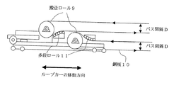
図1乃至図3において、1は駆動モータ、2は減速機、3はワイヤドラム、4はワイヤ、5はワイヤシーブ、6はガイドローラ、7はワイヤストッパー、8はループカー、9は搬送ロール、10は鋼板、11は多段ロールを示す。
The best mode for carrying out the invention will be described in detail with reference to FIGS.
1 to 3 are diagrams illustrating an embodiment of a loop car according to the present invention. FIG. 1 is a plan view, FIG. 2 is a side view, and FIG. 3 is a detailed view of the loop car.
1 to 3, 1 is a drive motor, 2 is a speed reducer, 3 is a wire drum, 4 is a wire, 5 is a wire sheave, 6 is a guide roller, 7 is a wire stopper, 8 is a loop car, 9 is a transport roll, 10 Is a steel plate, 11 is a multistage roll.
図1において、ループカー8はワイヤ4により牽引されて、矢印の方向に前進・後退することによって、ループカー8の右側に貯蔵される鋼板長さを変えることができる。
ワイヤ4は、駆動モータ1により減速機2を介して駆動されるワイヤドラム3からワイヤシーブ5に掛け回された後にワイヤストッパー7に接続されて固定されている。
また、ループカーの上には、鋼板を搬送する複数の搬送ロール9が設置されており、図2の右側の矢印で示すように、搬送ロール9に鋼板を往復させて掛け回すことによって、単一の搬送ロールの場合に比べて2パス分多い鋼板を貯蔵するルーパーを構成することができる。
しかし、鋼板10をそのまま搬送ロール9に掛け回すと鋼板10のパス間隔は搬送ロールの直径に相当する間隔となってしまい、通常は、設備の寸法制約により、不可能であった。
一方、搬送ロール9の直径以下にパス間隔Dを縮小すると、図2のように搬送ロール同士が重なった配置になる。
鋼板10とパスの干渉をさけるため、パス変更をする必要があるが、設備の構造上同径のロールを設置することができず、小径のガイドロールによって鋼板10のパスラインを変更することによって鋼板のパス間隔Dを狭めようとすると、鋼板の曲げ抵抗が大きくなるうえ、鋼板自体に曲げ応力が働いて腰折れなどの原因となっていた。
In FIG. 1, the length of the steel plate stored on the right side of the loop car 8 can be changed by the loop car 8 being pulled by the wire 4 and moving forward and backward in the direction of the arrow.
The wire 4 is wound around the wire sheave 5 from the wire drum 3 driven by the drive motor 1 via the speed reducer 2 and then connected to the wire stopper 7 and fixed.
Further, on the loop car, a plurality of transport rolls 9 for transporting the steel plates are installed. As shown by the arrows on the right side of FIG. It is possible to configure a looper that stores a steel plate that is two passes more than the case of the transport roll.
However, when the steel plate 10 is wound around the transport roll 9 as it is, the pass interval of the steel plate 10 becomes an interval corresponding to the diameter of the transport roll, which is usually impossible due to the size constraints of the equipment.
On the other hand, when the path interval D is reduced to be equal to or smaller than the diameter of the transport roll 9, the transport rolls are arranged to overlap each other as shown in FIG.
In order to avoid interference between the steel plate 10 and the path, it is necessary to change the path, but due to the structure of the equipment, it is not possible to install a roll of the same diameter, When trying to narrow the pass interval D of the steel plate, the bending resistance of the steel plate increases, and bending stress acts on the steel plate itself, which causes the waist to break.
そこで本発明のループカー8は、鋼板10を貯蔵する横型ルーパー内を移動しながら該鋼板を搬送するループカーであって、前記鋼板10を搬送する複数の搬送ロール9を有し、図3に示すように、該搬送ロール9の入側または出側に多段ロール11を設置することにより、前記鋼板のパス間隔Dを前記搬送ロールの直径未満とすることを特徴とする。
すなわち、複数(本実施形態においては2基)の搬送ロール9の入側または出側に多段ロール11を設置することにより、搬送ロール9の入側または出側にあたかも大径ロールの様なパスを形成し、鋼板10を大きな曲率半径にて緩やかに曲げることによって、鋼板の曲げ抵抗の増加を極力抑え、搬送ロール9の半分程度のパス間隔Dを実現し、なおかつ、ロール間隔を縮小し設備を小型化することができるうえ、鋼板に過度の曲げ応力を働かせることがないので腰折れを防止することができる。
このように、本装置は、小径のロールを多数配置する多段ロール11を設けることにより大径ロールと同じ曲率でパスを形成し、パス変更による鋼板の曲げ抵抗の増加を抑えることができるうえ、鋼板に過度の曲げ応力を働かせることがないので腰折れを防止することができる。
なお、本実施形態における多段ロール11は、搬送ロール9の直径の約1/7程度の直径の小径ロールを5つ設けることによって、搬送ロール9の曲率半径の、約2倍の曲率半径を有するパスラインを形成しているが、小径ロールの径および数は、対象とする鋼板のサイズ、搬送ロール径、パス間隔などの条件によって適宜選択すればよい。
Therefore, the loop car 8 of the present invention is a loop car that transports the steel plate while moving in a horizontal looper that stores the steel plate 10, and has a plurality of transport rolls 9 that transport the steel plate 10, as shown in FIG. In addition, the multi-stage roll 11 is installed on the entrance side or the exit side of the transport roll 9 so that the pass interval D of the steel sheet is less than the diameter of the transport roll.
That is, by installing the multi-stage roll 11 on the entry side or the exit side of a plurality (two in this embodiment) of the delivery rolls 9, a path like a large-diameter roll on the entry side or the exit side of the delivery rolls 9. And gently bending the steel plate 10 with a large radius of curvature to suppress the increase in bending resistance of the steel plate as much as possible, to realize a pass interval D of about half of the transport roll 9, and to reduce the roll interval Can be reduced in size, and excessive bending stress is not applied to the steel sheet, so that it is possible to prevent hip breakage.
Thus, this apparatus can form a path with the same curvature as the large-diameter roll by providing the multistage roll 11 in which a large number of small-diameter rolls are arranged, and can suppress an increase in the bending resistance of the steel sheet due to the path change. Since excessive bending stress is not exerted on the steel sheet, it is possible to prevent hip breakage.
In addition, the multistage roll 11 in this embodiment has a curvature radius of about twice the curvature radius of the conveyance roll 9 by providing five small-diameter rolls having a diameter of about 1/7 of the diameter of the conveyance roll 9. Although the pass line is formed, the diameter and number of the small-diameter rolls may be appropriately selected depending on conditions such as the size of the target steel sheet, the diameter of the transport roll, and the pass interval.
搬送ロール直径が1000mmのループカーを用いて、板厚4.5mm、板幅1700mmの鋼板を搬送した結果を表1に示す。

ここに、ベンドロスとは、曲げ応力に起因する鋼板張力をいい、このベンドロス分だけ余分に引っ張らなければ鋼板を搬送することができない。
一方、本発明例に示すように多段ロールを用いて曲率半径を1000mmとした場合、ベンドロスは132 kgfとなり、大幅な減少効果があった。
また、複数の小径ロールからなる多段ロールとすることにより、曲率半径1000mmの大径ロールに比べて設備コストを大幅に低減できるうえ、慣性力が大幅に減少するため、ラインを容易に加減速することができる。
Table 1 shows the results of conveying a steel plate having a plate thickness of 4.5 mm and a plate width of 1700 mm using a loop car having a conveyance roll diameter of 1000 mm.
Here, the bendros refers to the steel plate tension resulting from the bending stress, and the steel plates cannot be conveyed unless they are pulled excessively by this bendros.
On the other hand, as shown in the examples of the present invention, when the curvature radius was set to 1000 mm using a multi-stage roll, the bendros was 132 kgf, and there was a significant reduction effect.
Also, by using a multi-stage roll consisting of multiple small-diameter rolls, the equipment cost can be significantly reduced compared to a large-diameter roll with a radius of curvature of 1000 mm, and the inertial force is greatly reduced, so the line can be easily accelerated and decelerated. be able to.
1 駆動モータ
2 減速機
3 ワイヤドラム
4 ワイヤ
5 ワイヤシーブ
6 ガイドローラ
7 ワイヤストッパー
8 ループカー
9 搬送ロール
10 鋼板
11 多段ロール
DESCRIPTION OF SYMBOLS 1 Drive motor 2 Reduction gear 3 Wire drum 4 Wire 5 Wire sheave 6 Guide roller 7 Wire stopper 8 Loop car 9 Transport roll 10 Steel plate 11 Multistage roll
Claims (2)
Priority Applications (1)
| Application Number | Priority Date | Filing Date | Title |
|---|---|---|---|
| JP2004098301A JP4268552B2 (en) | 2004-03-30 | 2004-03-30 | Loop car and method for enhancing the same |
Applications Claiming Priority (1)
| Application Number | Priority Date | Filing Date | Title |
|---|---|---|---|
| JP2004098301A JP4268552B2 (en) | 2004-03-30 | 2004-03-30 | Loop car and method for enhancing the same |
Publications (2)
| Publication Number | Publication Date |
|---|---|
| JP2005279727A JP2005279727A (en) | 2005-10-13 |
| JP4268552B2 true JP4268552B2 (en) | 2009-05-27 |
Family
ID=35178660
Family Applications (1)
| Application Number | Title | Priority Date | Filing Date |
|---|---|---|---|
| JP2004098301A Expired - Fee Related JP4268552B2 (en) | 2004-03-30 | 2004-03-30 | Loop car and method for enhancing the same |
Country Status (1)
| Country | Link |
|---|---|
| JP (1) | JP4268552B2 (en) |
-
2004
- 2004-03-30 JP JP2004098301A patent/JP4268552B2/en not_active Expired - Fee Related
Also Published As
| Publication number | Publication date |
|---|---|
| JP2005279727A (en) | 2005-10-13 |
Similar Documents
| Publication | Publication Date | Title |
|---|---|---|
| CN103030026A (en) | Wire winding bobbin, wire winding method and wire winding apparatus | |
| JP5856535B2 (en) | Roller leveler and plate material correction method using the same | |
| CN102951470B (en) | Window adhering machine paper feeding device | |
| JP6593239B2 (en) | Shape correction device and shape correction method | |
| JP4268552B2 (en) | Loop car and method for enhancing the same | |
| JP2010201492A (en) | Forming apparatus of deformed wire material | |
| CN102089144A (en) | Driving means and device for working sheet-like material | |
| JP5803865B2 (en) | Manufacturing method of stainless steel cold-rolled steel strip | |
| JP2007044734A (en) | Wire straightening device and solar cell assembly wiring device | |
| JP4591175B2 (en) | Manufacturing equipment of brazing material clad sheet and manufacturing method thereof | |
| EP3120945A1 (en) | Coiler device provided with chute roller | |
| CN103649663A (en) | Walking beam heating furnace | |
| WO2019230791A1 (en) | Roll-forming device for food dough piece and roll-forming method therefor | |
| JP6514543B2 (en) | Method and apparatus for manufacturing rubber sheet containing steel cord | |
| JP3843763B2 (en) | Hot rolling equipment and hot rolling method | |
| JP2009131867A (en) | Steel pipe bending apparatus and steel pipe bending method | |
| JP2007307587A (en) | Extra fine wire drawing method and extra fine wire drawing apparatus | |
| JP5027547B2 (en) | Vertical looper and operating method thereof | |
| JP6408332B2 (en) | Bend straightening device | |
| WO2023228471A1 (en) | Metal strip and threading method therefor | |
| JP4849839B2 (en) | Ticket processing device | |
| RU2007103836A (en) | DEVICE FOR CONTINUOUS EXTENSION OF METAL TAPE STRETCHING AND METHOD OF OPERATION OF SUCH DEVICE | |
| JP3402982B2 (en) | Strip conveyor | |
| JP2013013917A (en) | Method and device for preventing meandering of steel strip | |
| JP6881421B2 (en) | Metal band process switching device |
Legal Events
| Date | Code | Title | Description |
|---|---|---|---|
| A621 | Written request for application examination |
Free format text: JAPANESE INTERMEDIATE CODE: A621 Effective date: 20061113 |
|
| A977 | Report on retrieval |
Free format text: JAPANESE INTERMEDIATE CODE: A971007 Effective date: 20090119 |
|
| TRDD | Decision of grant or rejection written | ||
| A01 | Written decision to grant a patent or to grant a registration (utility model) |
Free format text: JAPANESE INTERMEDIATE CODE: A01 Effective date: 20090217 |
|
| A01 | Written decision to grant a patent or to grant a registration (utility model) |
Free format text: JAPANESE INTERMEDIATE CODE: A01 |
|
| A61 | First payment of annual fees (during grant procedure) |
Free format text: JAPANESE INTERMEDIATE CODE: A61 Effective date: 20090220 |
|
| R151 | Written notification of patent or utility model registration |
Ref document number: 4268552 Country of ref document: JP Free format text: JAPANESE INTERMEDIATE CODE: R151 |
|
| FPAY | Renewal fee payment (event date is renewal date of database) |
Free format text: PAYMENT UNTIL: 20120227 Year of fee payment: 3 |
|
| FPAY | Renewal fee payment (event date is renewal date of database) |
Free format text: PAYMENT UNTIL: 20120227 Year of fee payment: 3 |
|
| FPAY | Renewal fee payment (event date is renewal date of database) |
Free format text: PAYMENT UNTIL: 20130227 Year of fee payment: 4 |
|
| FPAY | Renewal fee payment (event date is renewal date of database) |
Free format text: PAYMENT UNTIL: 20130227 Year of fee payment: 4 |
|
| S531 | Written request for registration of change of domicile |
Free format text: JAPANESE INTERMEDIATE CODE: R313531 |
|
| FPAY | Renewal fee payment (event date is renewal date of database) |
Free format text: PAYMENT UNTIL: 20130227 Year of fee payment: 4 |
|
| R350 | Written notification of registration of transfer |
Free format text: JAPANESE INTERMEDIATE CODE: R350 |
|
| FPAY | Renewal fee payment (event date is renewal date of database) |
Free format text: PAYMENT UNTIL: 20130227 Year of fee payment: 4 |
|
| S533 | Written request for registration of change of name |
Free format text: JAPANESE INTERMEDIATE CODE: R313533 |
|
| FPAY | Renewal fee payment (event date is renewal date of database) |
Free format text: PAYMENT UNTIL: 20130227 Year of fee payment: 4 |
|
| R350 | Written notification of registration of transfer |
Free format text: JAPANESE INTERMEDIATE CODE: R350 |
|
| FPAY | Renewal fee payment (event date is renewal date of database) |
Free format text: PAYMENT UNTIL: 20140227 Year of fee payment: 5 |
|
| S533 | Written request for registration of change of name |
Free format text: JAPANESE INTERMEDIATE CODE: R313533 |
|
| R350 | Written notification of registration of transfer |
Free format text: JAPANESE INTERMEDIATE CODE: R350 |
|
| LAPS | Cancellation because of no payment of annual fees |