JP4268445B2 - Mechanical crusher - Google Patents
Mechanical crusher Download PDFInfo
- Publication number
- JP4268445B2 JP4268445B2 JP2003135619A JP2003135619A JP4268445B2 JP 4268445 B2 JP4268445 B2 JP 4268445B2 JP 2003135619 A JP2003135619 A JP 2003135619A JP 2003135619 A JP2003135619 A JP 2003135619A JP 4268445 B2 JP4268445 B2 JP 4268445B2
- Authority
- JP
- Japan
- Prior art keywords
- rotor
- refrigerant
- liner
- groove
- pulverized
- Prior art date
- Legal status (The legal status is an assumption and is not a legal conclusion. Google has not performed a legal analysis and makes no representation as to the accuracy of the status listed.)
- Expired - Lifetime
Links
Images


Description
【0001】
【発明の属する技術分野】
本発明は、食品や医薬品用有機物、あるいは熱可塑性のプラスチック等のように、熱によって変質しあるいは溶融して融着するような、熱に弱い粉粒体原料を微粉砕するために、粉砕室の内部が高温になることを防止した回転型の機械式粉砕装置に関するものである。
【0002】
【従来の技術】
熱に弱い粉微粒体、例えば、加熱して融着させることによって画像等を生成する乾式トナーや粉体塗料等の熱に弱い熱可塑性のプラスチックの微細な粉粒体の製造においては、最終製品の粒径や粒度分布の調整のために、乾式による機械的な粉砕処理がなされており、このような粉粒体原料(以下、被粉砕物という)を微粉砕するための回転型の機械式粉砕装置が、従来から、種々提案されている。(例えば、特許文献1および特許文献2参照)。
【0003】
ここで、特許文献1に開示されている機械式粉砕装置は、回転軸に支持されて高速回転し、外周の表面の母線に沿って多数の矩形状の凸部が連続する歯形を有する円筒状の回転子(ロータ)と、この回転子との間に1mm以下の間隙で嵌装され、その内周の表面に三角形の形状をした凹部と凸部とが連続する歯形を有しており、この歯形の頂角が45〜60度に形成された固定子(ライナ)と、固定子の内周面の上端または固定子の途中に設けられ、固定子の凹部の開口面を閉鎖する分級リングと、固定子の外周に設けられた冷却ジャケットとを有し、被粉砕物を0〜5℃の低温空気と共に供給して、低温空気に乗せて供給した被粉砕物を微粉砕する回転型の機械式粉砕装置である。
【0004】
また、特許文献2に開示されている機械式粉砕装置は、周知の機械式粉砕装置と同様の第1粉砕部と、特許文献1に開示されている機械式粉砕装置と同様の第2粉砕部とを単一のケーシング内に配置し、この第2粉砕部の固定子の外周(ケーシングの外周)に冷却ジャケットを設けて、第1粉砕部と第2粉砕部との回転子を単一の回転軸で回転駆動するように構成して、第2粉砕部を冷却ジャケットで冷却しながら、被粉砕物を0〜5℃の低温空気と共に供給して、第1粉砕部で周知の機械式粉砕装置と同様に粉砕し、第2粉砕部で特許文献1に開示されている機械式粉砕装置と同様に微粉砕するように構成したものである。
【0005】
そして、特許文献1の機械式粉砕装置および特許文献2の第2粉砕部として開示されている機械式粉砕装置は、被粉砕物を粉砕することによって生じる発熱によって、乾式トナーや粉体塗料等の熱に弱いプラスチックからなる被粉砕物が溶融して相互に融着したり、固定子や回転子に融着したりして粉砕不可能となり、あるいは、食品や医薬品用有機物等の熱によって変質する可能性のある被粉砕物に熱的変化が生じることを防止するために、この機械式粉砕装置に、0〜5℃の低温空気を吸引導入して、この低温空気に乗せて被粉砕物を粉砕装置に導入することによって被粉砕物の温度の上昇を防止すると共に、固定子の外周に配置された冷却ジャケットに冷媒を通して、回転子と固定子との間の間隙(すなわち、粉砕室)や、固定子の凹部の空気および被粉砕物を冷却するものである。
【0006】
特許文献1および2に開示された機械式粉砕装置では、粉砕装置内に導入された被粉砕物は、空気流に乗って回転子と固定子との間に形成された粉砕室内に入って粉砕作用を受け、ミクロンオーダないし10数ミクロンの微粉砕製品となって空気と共に粉砕装置の外部に排出される。排出された微粉砕製品は、バグフィルターによって微粉砕製品と空気とに分離される。そして、空気は吸引送風機を経由して排気され、微粉砕製品は、バグフィルターで分離されて、ホッパーに送られて貯留される。
【0007】
特許文献1および2によれば、この機械式粉砕装置は、独特の歯形を有する固定子と回転子および分級リングによって、被粉砕物を確実かつ十分に、しかも効率良く微粉砕することができるので、ミクロンオーダないし10数ミクロンの微粉砕製品を短時間で容易に得ることができるとしている。また、粉砕装置内に被粉砕物と共に低温空気を吸引導入することによって排気温度を抑えることができると共に、冷却ジャケットで冷却することによって、従来不可能であった固定子の局部的な温度上昇も抑えることができるので、軟化点の低い被粉砕物でも粉砕不可能となることがなく円滑に粉砕でき、また熱によって質的な変化の生じる被粉砕物でも熱的変化を受けることなく粉砕できるとしている。
【0008】
そして、この機械式粉砕装置では、被粉砕物をミクロンオーダないし10数ミクロンの粒度に微粉砕するために粉砕室となる回転子と固定子との間の間隙を1mm以下に設定しているので、冷却ジャケットによる冷却の効果は、この間隙が1mm以下と極めて小さいために熱貫流係数が大きくなり、極めて効率が良く、冷却効果が著しいとしている。
【0009】
しかし、一方では、このように粉砕室の間隙を狭くすると、粉砕室の容量が減少して処理能力が低下し、単位時間当りの処理量が極端に少なくなり、生産性が極めて悪くなるという問題が生じる。このため、特許文献1および2に開示された機械式粉砕装置を使用して微粉砕を行うときには、その処理能力を向上させるために、被粉砕物の供給量を増やして粉体濃度を上げたり、回転子をさらに高速回転させたりして粉砕を行う必要があった。
【0010】
しかしながら、食品、医薬品用有機物や熱可塑性のプラスチック等の熱に弱い粉粒体原料(被粉砕物)は一般に熱伝導率が低く、被粉砕物の供給量を増やして粉体濃度を上げると粉砕室内の熱伝導率が低下して、冷却のための熱効率が悪くなる。また、回転子の回転速度を上げると、粉砕時の摩擦熱等によって回転子、固定子、被粉砕物、粉砕室内の空気等の温度が上昇する。このため、粉体濃度を上げると共に回転子の回転速度を上げると、両者の相乗効果によりさらに粉砕室内の温度が上昇することになる。
【0011】
この温度上昇を抑えるために、特許文献1および2に開示された機械式粉砕装置では、前述のように、0〜5℃の低温空気を粉砕装置の内部に吸引導入して空冷すると共に、冷却ジャケットに冷媒を通して、回転子と固定子との間の間隙や固定子の凹部に存在する空気および被粉砕物を、固定子を介して冷却ジャケット内の冷媒と熱交換させながら、被粉砕物を微粉砕している。
【0012】
しかし、冷却ジャケットによる冷却では、固定子側の冷却は効果的にできるものの、発熱量の大きい回転子側の冷却効果は、粉砕室の空気層(正確には空気と被粉砕物の混合した層)を介して冷却するので冷却効果が極めて低く、効率的に冷却することができないという問題があった。このため、生産性を向上させるために粉砕室内の粉体濃度を上げたり、回転子の回転速度を上げたりすると、冷却ジャケットによる冷却効果が必ずしも十分でなく、被粉砕物が回転子の表面に融着を起こしてしまい、それ以上の粉砕処理の続行が困難もしくは不可能となることや、熱によって被粉砕物に質的な変化の生じるという問題が依然として残されていた。
【0013】
【特許文献1】
特公昭63−66583号公報(第3〜5頁、第5図、第10図)
【特許文献2】
特公昭63−66584号公報(第3〜6頁、第5図、第12図)
【0014】
【発明が解決しようとする課題】
本発明の目的は、上記従来技術の問題点を解消し、融着して粉砕不能になったり、熱によって品質が劣化したりすることなく、熱に弱い粉粒体原料を効率良く微粉砕することができ、生産性を向上させることができる機械式粉砕装置を提供することにある。
【0015】
【課題を解決するための手段】
前記の課題を解決するために、本発明に係る機械式粉砕装置は、回転可能に支持され、外周面に複数個の溝が形成されたロータと、このロータの外側に前記ロータの外周面と所望の間隙を設けて配置され、その内周面に複数個の溝が形成されたライナとを備え、前記間隙で被粉砕物を粉砕処理する機械式粉砕装置であって、前記ロータの溝および前記ライナの溝のうちの少なくとも一方は、被粉砕物の流れを妨げる方向に傾斜しており、前記ロータは、回転軸と、この回転軸に積層して嵌装されたほぼ同じ形状の複数個のロータユニットと、この複数個のロータユニットの両端部に配置され、積層された前記複数個のロータユニットの両端面を覆う2個の側板と、前記複数個のロータユニットと2個の側板とを一体的に固定する固定ボルトとを備え、前記複数個のロータユニットには、それぞれ、外周部に沿って、前記内側冷媒循環路を構成する冷媒貯留部と、この冷媒貯留部を相互に連通する連通孔とが形成されており、前記回転軸に一体的に固定されていることを特徴とする。
【0016】
ここで、本発明に係る機械式粉砕装置においては、前記冷媒貯留部を相互に連通する前記連通孔が、前記ロータユニットの外周部に沿って複数個設けられていることが好ましく、前記ロータユニットの前記冷媒貯留部の内側には、前記冷媒貯留部を前記ロータユニットの外周部のみに限定するための冷媒遮蔽部が形成されていることが好ましい。
【0017】
また、前記ロータユニットに形成された前記冷媒遮蔽部が、前記冷媒貯留部と隔壁で隔てられた空間であることが好ましく、前記ロータユニットに形成された前記冷媒遮蔽部が、前記冷媒貯留部の内側に配置された軽量化された遮蔽物であることが好ましく、前記軽量化された遮蔽物が、発泡プラスチックで形成されていることが好ましい。
【0023】
【発明の実施の形態】
以下に、添付の図面に示す好適な実施の形態に基づいて、本発明の機械式粉砕装置を詳細に説明する。
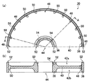
図1は、本発明の第1の実施例に係る機械式粉砕装置を示す断面模式図、また、図2は、その中のロータユニットの詳細を示す図で、同(a)は上半分のみを示した平面図、同(b)は同(a)のA−A線断面図である。なお、ここで、図2は、図1に示す機械式粉砕装置において、両端部(例えば、最上部)に配置されたロータユニットを描いたものである。
【0024】
本実施例に示す機械式粉砕装置(以下、単に粉砕装置10という)は、食品、医薬品用有機物あるいは熱可塑性のプラスチック等の熱に弱い粉粒体原料(被粉砕物)を微粉砕するための縦型の機械式粉砕装置であり、基本的な構成として、縦型に配置された円筒状のケーシング12と、このケーシング12に回転可能に支持された回転軸14と、この回転軸14によってケーシング12内を回転可能に支持され、外周面に複数の溝が形成されたロータ16と、このロータ16の外側に、ロータ16の外周面と所望の間隙を設けて配置され、その内周面に複数の溝が形成されたライナ18とを備えており、ライナ18はケーシング12の内面に固定されている。そして、ロータ16とライナ18との間隙で被粉砕物を粉砕処理するものである。
【0025】
この粉砕装置10において、ケーシング12は、中空の円筒形をした容器であり、図1に示す実施例では、その左下側に、粉砕される粉粒体原料である被粉砕物が供給される原料供給口20が設けられており、左上側に、粉砕された後の粉砕製品が排出される製品排出口22が設けられている。また、ケーシング12の下側には脚部が設けられており、この脚部により、ケーシング12は、図示しない据付台等に取り付け可能に構成されている。
【0026】
なお、この実施例のケーシング12とライナ18とは、図示されていないが、製造上の便宜のために、例えば、回転軸14に平行な分割線で複数個のユニットに分割されている。ただし、本発明はこの構造に限定されるものではなく、ケーシング12を構成するユニットの個数に制限がないのはもちろん、上下方向にも複数個に分割したり、全体を一体で製造した一体型のケーシング12として構成することも可能である。
【0027】
ケーシング12の原料供給口20には、スクリューフィーダ等の供給装置(図示せず)から被粉砕物が供給され、ケーシング12の製品排出口22は、ブロア等の空気吸引装置(図示せず)によって吸引されている。そして、この空気吸引装置によって吸引することによって、原料供給口20から供給された被粉砕物はケーシング12内に空気と共に吸引導入され、ロータ16とライナ18との間隙によって構成された粉砕室28を通過し、ロータ16が回転することによって粉砕され、粉砕製品が空気と共に製品排出口22から排出される。
【0028】
回転軸14は、ケーシング12の内部を上下に貫通するように、粉砕装置10の設置面に対して垂直な方向に配設されており、ケーシング12の上下の端面の中央部に設けられた軸受24aおよび24bを介して支持されている。また、回転軸14の内部には、その軸方向の両端部と両端のロータ16との間に、被粉砕物等を冷却するために、ロータ16の内部を循環する冷媒の供給排出路26がそれぞれ形成されている。
【0029】
ここで、ロータ16の軸方向の長さ(高さ)は、ケーシング12の軸方向の長さ(高さ)よりも短く、ロータ16は、ケーシング12内部の軸方向のほぼ中央に配置される。その結果、ケーシング12の内部には、上部および下部に所定の空間が形成される。そして、この実施例では、下側の空間は原料供給口20に通じており、上側の空間は製品排出口22に通じている。この空間の容積や形状は必要に応じて適宜決定することができる。ライナ18は、ロータ16の軸方向の長さ(高さ)にほぼ相当する長さ、あるいはロータ16よりわずかに長い長さであって、ロータ16に対向する位置に、ケーシング12の内周面に装着されている。
【0030】
回転軸14の一方の端部、例えば上端部(軸受24a側)の冷媒の供給排出路26には、冷媒(例えば冷却水)の供給口として供給ジョイント(図示せず)が接続されており、回転軸14の一方の端部、例えば下端部(軸受24b側)の冷媒の供給排出路26には、冷媒の排出口として排出ジョイント(図示せず)が接続されている。この供給ジョイントと排出ジョイントとは、回転軸14が高速回転しているときに冷媒を供給するものであって、高速回転に対応できるロータリージョイントが使用される。
【0031】
そして、後述するように、ロータ16が回転して、ライナ18とロータ16との間隙として形成された粉砕室28で被粉砕物を粉砕する際に、冷媒がこの供給口から供給されて、ロータ16の内部を循環した後、排出口から排出されることによってロータ16を内部から冷却する。この実施例では、回転軸14の上端部に供給口が、下端部に排出口が設けられているので、冷媒が自重で自然流下することを防止して、常にロータ16の内部に冷媒が充満しているように、排出口に制御弁を設けることが好ましい。
【0032】
この冷媒の供給口と排出口は、上述したように、回転軸14の両方の端部に設けられる構造に限定されるものではない。例えば、図3に他の実施例として示すように、回転軸14の上端部(軸受24a側)のみに冷媒の供給口と排出口とを設け、回転軸14の上端部から冷媒を供給してロータ16の内部を循環した後、回転軸14の内部を還流して上端部から排出する構造を採用することができる。この実施例では、二重管となったロータリージョイント(図示しない)を使用して、回転軸14の上端部に設けられた二重管の構造をした冷媒の供給排出路26の外側の管路から冷媒を供給し、ロータ16の内部を循環した後、二重管の内側の管路から冷媒を排出するように構成されている。そして、このように構成することによって、排出口に制御弁を設けることなく、常に冷媒をロータ16の内部に充満しておくことができる。
【0033】
さらに、回転軸14の一方の端部(例えば、回転軸14の下端部)には、プーリおよび伝動ベルト等の巻掛伝動機構や歯車伝動機構等(図示せず)の任意の伝動機構を介して、モータ等の駆動装置(図示せず)に連結されている。そして、ロータ16を回転して被粉砕物を粉砕する時には、この駆動装置からの駆動力が伝動機構を介して回転軸14に伝導され、回転軸14を所定の回転速度で回転させる。
【0034】
この実施例では、ロータ16は、回転軸14と、この回転軸14に積層して嵌装されたほぼ同じ形状の複数個(実施例では5個)のロータユニット30と、この積層された5個のロータユニット30の両端部に配置され、積層されたロータユニット30の両端面を覆う2個の円形の側板32a,32bと、ロータユニット30と側板32a,32bとを一体的に固定する固定ボルト34とを備えており、図示しないキーで回転不能にされて、固定ボルト34で回転軸14に一体的に固定されている。それぞれのロータユニット30は、図2に示すように、所定の厚さ(高さ)を有しており、中央のボス36と外周のロータ部38、およびボス36とロータ部38を接続するリム40からなっている。そして、ボス36とロータ部38とは同じ厚さ(高さ)であり、リム40の逃げ部が、詳細は後述するように、ロータ16の内部を冷媒が循環してロータ16を内部から冷却する冷媒貯留部42a,42bとなっている。
【0035】
ここで、ロータユニット30の厚さおよびその端面の直径は、共に何ら制限はなく、必要に応じて適宜決定することができる。ここでは、説明を容易にする目的から、ロータユニット30の上側の端面を単に上面、下側の端面を単に下面という。冷媒貯留部42aと42bとを隔てているリム40の板厚は、0.01≦リムの板厚/ロータの直径≦0.3とすることが好ましい。また、ロータ16の厚さも、ロータの厚さ/ロータの直径≦0.3とすることが好ましく、0.01≦ロータの厚さ/ロータの直径≦0.2とすることがさらに好ましい。
【0036】
なお、この実施例では、ロータ16は、回転軸14に対して垂直な面で分割された5個のロータユニット30を積層して構成されているが、これも製造上の便宜のためである。従って、本発明はこれに限定されず、ロータ16を構成するロータユニット30の個数や、個々のロータユニット30の厚さ(高さ)に制限がないのはもちろん、全体を一体で製造した一体型のロータ16として構成することも可能である。
【0037】
ロータユニット30の中心には、回転軸14を挿入する中心孔44が穿孔されている。ロータ16は、この中心孔44に回転軸14を挿入して積層し、図示しないキーによって回転軸14に対して回り止めされ、フランジ46a,46bで回転軸14の所定位置に固定される。また、ロータユニット30には、重量を軽くしてモータの負荷を軽減するために、リム40の逃げ部としてドーナツ状の空間(冷媒貯留部42a,42b)が形成されている。そして、この空間は、図1に示すように、ロータユニット30および側板32a,32bを連結してロータ16を構成したときに、ロータ16の内部に循環される冷媒を貯留するため冷媒貯留部42a,42bを形成する。なお、冷媒貯留部42a,42bの容積は、後述するように、空間の容積に限定されるものではなく、必要に応じて適宜決定することができる。
【0038】
冷媒貯留部42a,42bの外周部に沿って、ロータユニット30および側板32a,32bを連結し、一体的に固定するための固定ボルト34(図1参照)が挿入される複数のボルト孔48と、ロータユニット30の相互の間で冷媒を循環させるための複数の連通孔50が開口されている。図2に示す実施例では、固定ボルト34が挿入されるボルト孔48は、中心孔44を中心として45度間隔で穿孔されており、冷媒を循環させるための連通孔50は、ボルト孔48の間に15度間隔で2個ずつ穿孔されている。
【0039】
なお、固定ボルト34が挿入されるボルト孔48および冷媒を循環させるための連通孔50は、そのサイズ、形状、個数、配置等に何ら制限はなく、必要に応じて適宜決定することができるが、冷媒を循環させるための連通孔50は、ロータ16を高速回転させる際に発生する応力を低減し、ロータユニット30が破壊されるのを防止するという点においても、被粉砕物等の冷却効果を向上させるという点においても、外周部に沿って配置することが好ましく、応力による影響を考慮した上で、極力多く、もしくは大きな孔を開口することが好ましい。
【0040】
また、連通孔50の穿孔位置は、ロータユニット30の半径をR、ロータユニット30の中心からの連通孔50の中心までの距離(半径)をrとしたときに、0.4≦r/R≦0.96とすることが好ましい。連通孔50の形状、寸法、数による制限はないが、円形の孔のとき、同一円周上に配置された連通孔50の全長は、円周長さの50%以下にすることがさらに好ましい。
【0041】
全てのロータユニット30および2個の側板32a,32bを積層し、ボルト孔48に連結用の固定ボルト34を挿入して固定することによって、ロータ16が構成される。このように連結することによって、ロータ16には、前述したように、隣接するロータユニット30同士、および端部のロータユニット30と側板32a,32bとの間に、ロータ16の内部に循環される冷媒を貯留する冷媒貯留部42a,42bが形成される。
【0042】
ロータユニット30のボス36に穿孔された中心孔44の外周部ならびにロータユニット30の外周部のロータ部38には、Oリングを装着するためのOリング溝52が形成されている。このOリング溝52は、冷媒が冷媒貯留部42a,42bから漏洩することを防止するためのものであって、Oリング溝52にOリング(図示しない)を装着し、ロータユニット30と側板32a,32bを積層して固定することによって、冷媒貯留部42a,42b(図1では双方を併せて冷媒貯留部42とする)と回転軸14との間、および冷媒貯留部42a,42bとロータ16の外周面との間が完全にシールされる。
【0043】
このOリング溝52は、図2ではロータユニット30の上面のみに形成されているが、ロータ16を構成する5個のロータユニット30の任意の1個(一般的には中央の1個)には、上面と下面の両方にOリング溝52を形成する。このように構成することによって、ロータユニット30と側板32a,32bとを積層する全ての面にOリング溝52を形成して、ロータ16の冷媒貯留部42と中心孔44または外周面との間を完全にシールすることができる。
【0044】
両端部のロータユニット30と側板32a,32bとによって形成される冷媒貯留部42には、回転軸14の軸方向に沿って穿孔されている冷媒の供給排出路26(図1参照)と接続するための複数の接続孔54が設けられている。この接続孔54の個数や配置は何ら限定されるものではないが、本実施例では、ロータユニット30の中心孔44を中心として、90゜毎に1つずつ、合計で4箇所が接続孔54として開口されている。
【0045】
また、図1に示すように、回転軸14の内部に設けられている冷媒の供給排出路26と回転軸14の外周面との間にも、ロータユニット30に設けられている複数の接続孔54の位置に対応して、同じ数の接続孔56(図1参照)が設けられている。そして、回転軸14にロータユニット30を嵌装するときに、図示しないキーによって回転軸14に設けられている複数の接続孔56と両端部のロータユニット30に設けられている複数の接続孔54とを正確に位置決めして固定される。
【0046】
このように、回転軸14に設けられた冷媒の供給排出路26と接続孔56、およびロータユニット30に設けられた接続孔54と冷媒貯留部42とによってロータ16を内側から冷却する内側冷媒循環路が構成されているので、被粉砕物の粉砕時に、内側冷媒循環路に冷媒を循環させるときには、図示していない冷媒の供給装置によって回転軸14に冷媒が供給され、冷媒の供給排出路26、接続孔56,54を通って側板32aと最上部のロータユニット30とによって構成される冷媒貯留部42に貯留される。
【0047】
冷媒貯留部42には、その容積に相当する所定量の冷媒が貯留される。また、冷媒貯留部42に貯留された冷媒は、新たな冷媒が供給されるに従って外周部に穿孔された連通孔50から溢流して、次段のロータユニット30によって構成される次段の冷媒貯留部42に流れ、以下、順次、次段の冷媒貯留部42に流れていく。そして、最下部のロータユニット30と円形の側板32bとによって構成される最下段の冷媒貯留部42に到達して貯留された冷媒は、冷媒貯留部42から溢流して、接続孔54,56を経て回転軸14の内部に形成された冷媒の供給排出路26を通って外部へ排出される。このようにして、供給された冷媒は、ロータ16内部に形成された冷媒貯留部42の間で循環し、ロータ16および粉砕室28内の空気や被粉砕物等を冷却する。
【0048】
ここで、以上に説明した冷媒の循環は、ロータ16の上方から冷媒を供給して下方から排出するように構成しているが、これは、被粉砕物の移動方向に対向して冷媒を循環させる向流式としたものであって、冷却効率の点では、向流式の方が好ましい。しかし、冷媒を十分に供給することができるならば、冷媒を被粉砕物の移動方向と並行する方向に循環させる並流式とすることができる。冷媒をロータ16の下側から上側に向かって循環させる並流式とすると、冷媒貯留部42の空気が抜けやすくなり、冷媒が確実に冷媒貯留部42に充満するという利点がある。
【0049】
以上の説明では、冷媒として冷却水を例示したが、常温の冷却水に限定されるものではなく、任意の冷却装置で冷却した冷却水とすることができ、あるいは、任意の冷却装置で冷却した不凍液とすることもできる。冷媒として不凍液を採用すると、冷媒を0℃以下の温度に冷却することができるので、より効率の高い冷却を行うことができる。
【0050】
また、冷媒は、液状の冷媒に限られるものではなく、ガス状の冷媒、例えば冷却した乾燥空気とすることができる。そして、冷却した乾燥空気を冷媒として採用すると、冷媒貯留部42から外部に漏洩しても格別の支障はないので、ロータユニット30の相互の間および側板32a,32bとの間のシールを簡略化し、あるいは省略することができる。また、冷媒として、気化することによって冷却するアンモニア等の冷媒を採用することもできる。冷媒としてアンモニア等の冷媒を採用すると、漏洩しないようにシールを確実にしなければならないが、高い冷却効率を得ることができる。
【0051】
本実施例の機械式粉砕装置では、このように構成されており、ロータ16の内側に冷媒貯留部42が形成されているので、ロータ16を内側から冷却することができ、粉体濃度の高い粉砕処理を行い、あるいはロータ16を高速回転することによって粉砕室28が高温になり、被粉砕物が融着して粉砕不能になったり、熱によって品質が劣化したりすることを防止することができて、熱に弱い粉粒体原料を効率良く微粉砕することができ、生産性を向上させることができる機械式粉砕装置を提供するができる。さらに、冷却効率を向上させるためには、ケーシング12内に被粉砕物と共に冷却用の低温空気(冷却空気)を供給し、この低温空気に乗せて、被粉砕物を原料供給口20から供給するようにすることが好ましい。
【0052】
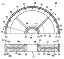
図3および図5は本発明の第2の実施例および第3の実施例に係る機械式粉砕装置を示す断面模式図であり、図4および図6は、図3および図5の実施例におけるロータユニットの詳細を示すもので、図4および図6(a)は上半分のみを示した平面図、同(b)は同(a)のA−A線断面図である。ここで、図4および図6は、図3および図5に示す機械式粉砕装置において、両端部(例えば、最上部)に配置されたロータユニットを描いたものである。
【0053】
ここで、第2の実施例を示す図3および図4、第3の実施例を示す図5および図6では、説明の重複を避けるために、第1の実施例を示す図1および図2と共通の構造の部分には同じ符号を付して説明を省略し、構造の異なる部分のみを説明する。
【0054】
図3および図4において、ロータ16を構成するロータユニット30には、冷媒貯留部42の内側に、冷媒貯留部42をロータユニット30の外周部のみに限定するための冷媒遮蔽部として、隔壁58が設けられている。この隔壁58は、冷媒貯留部42に貯留される冷媒の量を制限して、全体の重量を軽減すると共に高速回転するロータ16の遠心力によって生じる冷媒貯留部42の内圧を軽減するものである。
【0055】
この実施例における冷媒遮蔽部は、リム40の逃げ部として形成されるドーナツ状の空間を、隔壁58で外側の冷媒貯留部42a,42bと、その内側の隔壁58で隔てられた空間60a,60bとに分割するものであって、外側の冷媒貯留部42a,42bのみに冷媒を循環させるように構成されている。そして、この実施例の冷媒供給経路は、回転軸14の冷媒の供給排出路26から接続孔54を介して供給され、ロータユニット30の接続孔56に連通する中継管62(図4参照)によって隔壁58の接続孔64に接続されている。
【0056】
さらに、隔壁58の上面にOリング溝52を形成して、図示しないOリングを装着することによって冷媒が空間60a,60b側に漏洩することを防止する。このように構成することによって、中央のボス36に穿孔された中心孔44の外周部のOリング溝は省略することができる。そして、このように構成することによって、内側の空間60a,60bに相当する量の冷媒の重量を軽減することができ、遠心力によって生じる冷媒貯留部42の内圧も大幅に軽減することができる。
【0057】
また、この実施例では、図3に示すように、ケーシング12の外周部のライナ18の位置に対応する部分には、外部冷媒循環路が設けられている。この外部冷媒循環路は、冷却用ジャケット66内に冷媒を循環するものであって、被粉砕物の粉砕処理をするときに、この冷却用ジャケット66内に冷媒を循環させて、ケーシング12の外側からライナ18を冷却しながら粉砕を行うものである。このように構成することによって、さらに粉砕室28内の被粉砕物や空気を低温に保つことができる。
【0058】
図5および図6に示す第3の実施例では、ロータ16を構成するロータユニット30の冷媒貯留部42の内側に、冷媒遮蔽部として、軽量化された遮蔽物68を配置したものである。この遮蔽物68としては、プラスチック等の軽量な材質のものが好ましく、特に、発泡ポリエチレン等の発泡プラスチックで形成することが好ましい。発泡プラスチックは弾性を有しているので、冷媒貯留部42a,42bの厚さ(高さ)よりわずかに厚い発泡プラスチックのドーナツ状のリングを装着すると、ロータユニット30を積層してロータ16を形成するために固定ボルト34で固定する際に、ロータユニット30で押圧されて密着するので、特別のシールを必要としない利点がある。
【0059】
そして、この実施例の冷媒供給経路は、回転軸14の冷媒の供給排出路26から接続孔54を介して供給された冷媒を、遮蔽物68に形成された接続溝70で冷媒貯留部42aに連通することによって容易に形成することができる。この場合、遮蔽物68が回転して接続孔54が接続溝70と連通しなくなることを防止するために、任意の固定手段、たとえばネジ止めや接着によってロータユニット30と遮蔽物68とを固定することが好ましい。
【0060】
また、高速回転するロータ16の遠心力によって遮蔽物68が破損するおそれがあるときには、遮蔽物68の外周に、十分な強度を有する金属性の帯状のリングを嵌着することによって破損を防止することができる。そして、この実施例では、冷媒貯留部42に貯留される冷媒の量を制限して、全体の重量を軽減すると共に高速回転するロータ16の遠心力によって生じる冷媒貯留部42の内圧を軽減することができる。
【0061】
次に、本発明の粉砕装置のもう1つの特徴部分であるロータ16の外周面およびライナ18の内周面の構造について詳細に説明する。ここで、図7は本発明の機械式粉砕装置のライナの1実施例を示す斜視図であり、図8はロータまたはライナの溝の傾斜角度を説明する展開図、図9はロータまたはライナの溝の詳細を説明する図であって、溝に直交する断面で示した断面図であり、(a)は空気流の渦を説明する模式図、(b)および(c)はライナの溝の詳細図、(d)および(e)はロータの溝の詳細図、(f)はロータおよびライナの溝による粉砕作用を示す模式図、(g)はロータの溝に生じる渦の例を示す模式図である。
【0062】
本発明の粉砕装置10では、ロータ16の外周面およびライナ18の内周面のいずれか一方、もしくは両方に複数の溝が形成され、かつ、これらの溝が被粉砕物の流れを妨げる方向に傾斜して配置されている。例えば、図7にライナ18の例を示すように、その内周面に形成されたライナ18の溝72は、太い一点鎖線で示す回転軸14の回転中心(回転軸14の中心線)14aに対して、その包絡線のみが太い点線で示されているロータ16の回転方向(矢印bで示す)の逆方向に傾斜して形成されている。
【0063】
ここで、図7において、ライナ18は、その6分の1を構成するライナユニット18aのみが示され、その他の部分は細い点線で包絡線のみが示されている。もちろん、ライナ18を構成するライナユニットの数に制限はなく、ライナ18を1個の円管状に構成してもよいことはいうまでもない。なお、本発明において、回転軸14の方向とは、回転軸14の回転中心14aに平行な方向であって、矢印aで示す空気の流れの方向を意味し、ロータ16またはライナ18の長手方向およびその母線方向に等しい。また、矢印aで示す空気の流れの方向は、粉砕時の実際の空気の流れの方向ではなく、ロータ16が回転しないときに、原料供給口20から製品排出口22に向かって流れる空気の流れの方向を示している。
【0064】
前述したように、本発明においては、ロータ16の外周面の溝74およびライナ18の内周面の溝72の少なくとも一方の溝は、被粉砕物(粉砕粒子)の流れを妨げる方向に傾斜している。図8に展開して模式的に示すように、ロータ16の外周面とライナ18の内周面との間の間隙(粉砕室28)を移動する被粉砕物の移動速度のベクトル(粉砕粒子の流れの速度ベクトル)は、ロータ16の回転速度のベクトル(向き:回転方向b、長さ:速度)と空気の流れの速度ベクトル(向き:流れ方向a、長さ:速度)との合成ベクトル(向き:方向c、長さ:速度)で与えられる。
【0065】
そこで、ライナ18の内周面の溝72は、粉砕粒子の流れの速度ベクトルの方向(図に矢印cで示す方向)に対して交差する方向、好ましくは直交する方向に設けられる。すなわち、図8において、溝72は空気の流れの方向aに対して傾斜するように設けられる。ここで、空気の流れの方向aに対する溝72の傾斜角度θは、溝72が粉砕粒子の流れを妨げる方向に傾斜していれば特に制限はないが、被粉砕物の移動速度ベクトルcにできるだけ直交する方向、すなわち、好ましくは5度以上90度未満であり、より好ましくは5度〜60度、さらに好ましくは5度〜45度、最も好ましくは10度〜30度であるのがよい。
【0066】
ライナ18の内周面における空気の流れの方向a(図8参照)に対して傾斜した溝(以下、傾斜溝という)72の形状および幅、深さ、ピッチなどを含む寸法は特に限定されず、例えば、ライナ18の溝72の方向と直交する断面での傾斜溝72の形状が、鋸歯状、台形状、矩形状、円弧状などのいずれであってもよいが、特に、図9(a)に示すように、一辺がロータ16のほぼ中心に向き、他辺がこの一辺と45〜60度の角度をなし、かつロータ16の回転方向bに対して後側が低くなる三角形状とするのが好ましい。
【0067】
ライナ18の内周面にこのような傾斜溝72を形成すると、ライナ18の内周面に形成された傾斜溝72が被粉砕物の流れを妨げる方向に傾斜しているので、粉砕室28を構成するロータ16とライナ18との間の間隙(粉砕室28)で粉砕される被粉砕物の粒子は、製品排出口22からブロアなどによって吸引されて移動する空気の流れの方向aに移動し難くなり、粉砕室28の空間を広く保ったままであっても、粉砕室28中に滞留する時間を長くとることができて、被粉砕物をより均一なサイズに微粉砕することができる。
【0068】
図9(b)および(c)に、ライナ18の傾斜溝72と直交する断面におけるライナ18の傾斜溝72の断面形状の代表例を示す。図9(b)および(c)に示すように、ライナ18の傾斜溝72の断面形状は、ロータ16の回転方向bに対する前側の面72aがロータ16の中心方向、すなわち一点鎖線Cで示す方向に対して所定角度αだけ傾斜しており、回転方向bに対する後側の面72bがロータ16の中心方向Cに対して回転方向bあるいはその逆方向に所定角度βだけ傾斜している。ここで、角度αおよびβは、回転方向bの方向に傾斜している角度を正(+)の角度とし、回転方向bと逆方向に傾斜している角度を負(−)の角度とする。
【0069】
ライナ18の傾斜溝72の傾斜角αおよびβは、傾斜角αが30度〜70度、傾斜角βが−30度〜30度(回転方向bと逆方向の傾斜角30度から回転方向bと同じ方向の傾斜角30度まで)の範囲内にあるのが好ましい。また、傾斜溝72の底部72cおよび隣接する傾斜溝72との間の凸部(歯形の頂部)72dの幅は、いずれも傾斜溝72のピッチpの1/2以下であることが好ましい。なお、傾斜溝72の底部72cは、図9(b)および(c)には直線部を形成するように描かれているが、底部72cの直線部をなくして三角形の頂点となす(底部72cの幅を0にする)か、図9(a)に示すように丸みを帯びた円弧状とすることがより好ましい。
【0070】
ロータ16の傾斜溝74の傾斜角についても、ライナ18の傾斜溝72と同様に、図8に示すように、傾斜溝74が空気の流れの方向aに対して傾斜するように設けられている。そして、これ以外に傾斜角についての特別の制限はなく、好適な条件についてもライナ18の傾斜溝72と全く同様である。さらに、ロータ16の傾斜溝74の形状および寸法についても、ライナ18の傾斜溝72と同様に特に制限はなくどのような形状であってもよい。しかし、図9(a)に示すように、ロータ16の中心に向う半径に対して、ロータ16の回転方向bの後方側に向かって、一辺が5〜25度、他辺が45〜60度の角度をなす三角形状とするのが好ましい。そして、このように構成することにより、ライナ18の傾斜溝72で述べた効果と同様の効果を得ることができる。
【0071】
ロータ16の傾斜溝74の断面形状は、図9(d)および(e)にロータ16の傾斜溝74と直交する断面形状を示すように、回転方向bに対する傾斜溝74の前側の面74aは、ロータ16の中心方向、すなわち、一点鎖線Cで示す方向に対して、ロータ16の回転方向bあるいはその逆方向に所定角度γだけ傾斜しており、回転方向bに対する後側の面74bは、中心方向Cに対して回転方向bに所定角度δだけ傾斜している。
【0072】
ロータ16の傾斜溝74の傾斜角γおよびδは、傾斜角γが−30度〜70度(回転方向bと逆方向の傾斜角30度から回転方向bと同じ方向の傾斜角70度まで)、傾斜角βが−70度〜−30度(回転方向bと逆方向の傾斜角で70度から30度まで)の範囲内にあるのが好ましい。また、傾斜溝74の底部74cおよび隣接する傾斜溝74との間の凸部(歯形の頂部)74dの幅は、いずれも傾斜溝74のピッチpの1/2以下であることが好ましい。なお、傾斜溝74の底部74cは、図9(d)および(e)には直線部を形成するように描かれているが、ライナ18の傾斜溝72と同様に、三角形の頂点となす(底部74cの幅を0にする)か、図9(a)に示すように丸みを帯びた円弧状とすることがより好ましい。
【0073】
この傾斜溝72および74は、ロータ16の外周面およびライナ18の内周面のいずれか一方に形成されていればその効果が生じるが、両方の周面に形成することによってより大きな効果を得ることができる。ロータ16の外周面に傾斜溝74を形成する場合には、図10に示すように、ロータ16を構成する5個のロータユニット30の隣合う接合面において、傾斜溝74に位相のずれが生じることなく傾斜溝74が滑らかに連続するように、回転軸14に5個のロータユニット30を位置決めするキー溝(図示せず)の位置を正確に位置合わせしておくことが好ましい。
【0074】
次に、本発明の好ましい実施の態様として、傾斜溝72および74の断面形状を限定する理由について説明する。本発明の粉砕装置10では、粉砕室28における粉砕温度の過度な上昇や粉砕動力の上昇を防ぐものであり、そのためには、図9(a)に模式図として描かれているように、ロータ16の回転によってライナ18の傾斜溝72およびロータ16の傾斜溝74の内部に発生する渦72sおよび74sの流れを過度に乱すことなく、かつ、傾斜溝72および74の内部に適切な強さの渦72sおよび74sを形成することが、粉砕性能向上のために必要である。ここで、渦72sはロータ16の回転により生じるライナ18の傾斜溝72の内部の流線のイメージを、渦74sはロータ16の傾斜溝74の内部の流線のイメージを示している。
【0075】
粉砕室28に投入された被粉砕物の粒子は、図9(f)に示すように、ロータ16の傾斜溝74の内側に生じる渦によって、ロータ16の傾斜溝74の内部に取り込まれ、後側の面74bに衝突してライナ18の方向にはじき飛ばされ、ライナ18の前側の面72aに衝突して粉砕される。粉砕された粒子のうち、粗い粒子は重いので、ライナ18の傾斜溝72の内部の渦72sの流れに乗れず、再び傾斜溝72から粉砕室28に放出され、同じように衝突を繰り返して粉砕作用を受ける。
【0076】
一方、粉砕されて細かくなった粒子は、ライナ18の傾斜溝72またはロータ16の傾斜溝74の内側に発生する渦72s,74sの流れに乗って傾斜溝72および74の内側に止まり、空気の流れaに乗って製品排出口22に向かって移動すると共に、ロータ16およびライナ18の傾斜溝72および74の山、谷が交互に高速ですれ違うことで生じる圧力の変動によってライナ18の傾斜溝72またはロータ16の傾斜溝74に衝突して、さらに粉砕されて所定の細かさまで粉砕される。このような粉砕の過程を考慮すると、好ましい溝の断面形状が次のように決められる。
【0077】
ロータ16の傾斜溝74の後側の面74bは、流れを過度に乱さず、排気温度の上昇を防止し、後側の面74bに衝突する被粉砕物粒子をライナ18の方向にはじき飛ばせるように、傾斜角δはロータ16の回転方向bとは逆方向に30〜70度の範囲内とすることが好ましい。また、ライナ18の傾斜溝72の前側の面72aは、ロータ16によりはじき飛ばされた被粉砕物の粒子が衝突したときに適切な衝撃が与えられるように、傾斜角αは回転方向に30〜70度の範囲内とすることが好ましい。
【0078】
ロータ16の傾斜溝74の内側の渦74sおよびライナ18の傾斜溝72の内側の渦72sは、空間が広く、適切な渦の大きさで安定していることが重要であり、傾斜溝74の前側の面74aの傾斜角γおよび傾斜溝72の後側の面72bの傾斜角βの角度をそれぞれ−30〜30度の範囲内にすることで、溝72および74の空間を広くとることができる。
【0079】
しかし、ロータ16の傾斜溝74の前側の面74aは、回転方向bとは逆方向の傾斜角γ(マイナスの傾斜角)を大きくとると、図9(g)に示すように、主渦以外にも渦が発生してしまうので、傾斜溝74から放出されるべき大きな粒子も傾斜溝74の中に留まり、製品の中に粗大な粒子が混入してしまうことになる。ここで、主渦とは、主に粉砕の作用を粒子に与える渦であり、図9(a)および図9(g)に符号72s,74sで示す渦である。
【0080】
また、傾斜角γを回転方向bに大きくとると、傾斜溝74の内側に生じた渦の一部が粉砕室28を流れる主流の中に放出されるようになって主渦が不安定になったり、主流が傾斜溝74の内側にまで入り込んで渦の大きさが小さくなったりすることが生じる。これらのことを考慮すると、傾斜角γは回転方向bに−30〜30度の範囲内、すなわち、回転方向bと逆方向に30度から回転方向bと同じ方向に30度までの範囲内とすることが好ましい。ライナ18の傾斜溝72の後側の面72bの傾斜角βも同様な理由から、回転方向bに−30〜30度の範囲内、すなわち、回転方向bと逆方向に30度から回転方向bと同じ方向に30度までの範囲内とすることが好ましい。
【0081】
次に、本発明において好ましい溝のピッチについて説明する。同じロータ16の径では、傾斜溝72,74のピッチpを小さくすると、傾斜溝72,74の数が多くなるので、傾斜溝72,74の前側と後側の面72a,72b,74a,74bに粒子が衝突する確率が高くなり細かい粒度の製品を得るためには好ましい。しかし、傾斜溝72,74の深さには、安定した適切な強さの渦を生成し、かつ主渦以外の渦の発生を抑えるために好適な範囲があるので、溝のピッチpを小さくすると溝の空間が狭くなり、処理能力が低下する等の問題が生じる。
【0082】
傾斜溝のピッチpは、被粉砕物の種類、原料となる粒子の粒径、製品の必要とする粒度等に依存するが、本発明の粉砕装置10の場合には、2mm〜10mm程度とすることが好ましい。例えば、傾斜溝のピッチpと原料粒子の粒径との間の関係を例に挙げて説明すれば、傾斜溝のピッチpは、原料粒子の最大径に基づいて、下記の式(1)により規定される間隔とするのが好ましい。
【0083】
p=kD+1 ……(1)
ここで、p:ロータ16の溝およびライナ18の溝の間隔(mm)
D:原料粒子の最大径(mm)
k:係数
ロータ16の傾斜溝74およびライナ18の傾斜溝72の少なくとも一方、好ましくは両方のピッチpを、この式(1)を満足する間隔とすることにより、被粉砕物である原料粒子の粉砕効率を向上させることができる。なお、ここで、上記係数kは、2〜3とすることが好ましい。
【0084】
また、傾斜溝72,74の深さは、ピッチpの1/5倍以上で3倍以下とすることが好ましい。このとき、傾斜溝のピッチpおよび傾斜溝の深さは、ロータ16の傾斜溝74とライナ18の傾斜溝72とで同じにすることが好ましいが、両者の溝72と74との間で異なっていても格別の支障は生じない。
【0085】
粉砕装置10のケーシング12の内部に供給された被粉砕物(原料粒子)は、ロータ16とライナ18との間の間隙によって形成される粉砕室28を通過することによって粉砕されて、その粒径が次第に細かくなる。ここで、前述したように、被粉砕物の粒径に応じた最適な粉砕溝(傾斜溝74,72)の間隔(ピッチp)が存在するために、粉砕部の位置によって粉砕溝の間隔を変えることで粉砕効率を向上させることができる。
【0086】
より具体的には、原料供給口20側から製品排出口22側へ向かうに従って、粉砕されて、被粉砕物の粒径が小さくなるので、段階的に粉砕溝の間隔を小さく設定するのが好ましい。なお、粉砕溝の間隔を段階的に小さく設定するのは、ロータ16の傾斜溝74およびライナ18の傾斜溝72のどちらか一方だけでもよいが、両方の傾斜溝72,74の間隔を段階的に小さく設定するのが最も好ましい。
【0087】
また、粉砕効率は、ロータ16の傾斜溝74の間隔(ピッチ)とライナ18の傾斜溝72の間隔(ピッチ)との間にも依存関係が存在する。本発明者らの研究および実験の結果によれば、ロータ16の傾斜溝74の間隔に対するライナ18の傾斜溝72の間隔の比が1〜2の間とするのが最も粉砕効率を高くすることができるということが分かっている。例えば、ロータ16の溝間隔を4mmとしたときに、ライナ18の溝間隔はその1〜2倍の範囲の4mm〜8mmとするのが最も好ましい。
【0088】
以上に説明したように、ロータ16の外周面にこのような形状の傾斜溝74を形成することによって、原料供給口20から供給された被粉砕物の粒子が粉砕室28を構成するロータ16とライナ18との間の間隙に入り、ロータ16の傾斜溝74に形成された凸部74d(図9(d)および(e)参照)に衝突して、被粉砕物の粒子が製品排出口22からブロアなどによって吸引されている空気の流れの方向とは逆の方向(原料供給口20側)へはじき飛ばされるため、粉砕室中に滞留する時間が長くなり、より微細な粉体に微粉砕することができる。
【0089】
また、前述したように、被粉砕物の流れを妨げる方向に傾斜した傾斜溝は、ロータ16の外周面およびライナ18の内周面のいずれか一方の周面のみに形成することができる。このようなときには、他方の周面に、回転軸14に平行な溝を形成することもできる。さらに、いずれか一方の周面または両方の周面に、被粉砕物の流れを妨げる方向に傾斜した傾斜溝と逆方向に傾斜した溝との両方を形成して、図11(a)に示すライナ18の展開図および図11(b)に示すロータ16の展開図のようにメッシュ状となった傾斜溝76とすることもできる。ここで、この傾斜溝76の傾斜角は、両方の傾斜角が回転軸14に対して同一の傾斜角で交差するようにすることもでき、あるいは異なる傾斜角度で交差するようにすることもできる。さらに、ライナ18の傾斜溝とロータ16の傾斜溝とを異なった角度とすることもできる。
【0090】
このように、メッシュ状となった傾斜溝76を形成した場合には、逆の見方をすると、ロータ16の外周面およびライナ18の内周面には、菱形または正方形の断面形状をした複数の柱状突起物が所定の間隔で形成されていると考えることもできる。傾斜溝の形成方法については特に制限はなく、ロータ16の外周面およびライナ18の内周面を切削加工することによって傾斜溝を形成する方法や、鋳造等によって凸部を形成する方法など、公知の形成方法のいずれの方法も適用することができる。そして、傾斜溝の表面には、必要に応じて耐摩耗処理をすることができる。
【0091】
本発明においても、粉砕室28となるロータ16の外周面とライナ18の内周面との間隙の寸法(幅)は、特に制限されるものではではなく、被粉砕物の種類や原料および製品の粒度分布などに応じて適宜選択することができる。しかし、本発明の粉砕装置10においては、その特徴的な傾斜溝が存在するので、粉砕室28の幅を従来より大きくすることができ、最大で3mm程度の幅に設定することができる。
【0092】
また、本発明の粉砕装置10では、空気吸引装置による吸引力とロータ16との回転速度は、円滑な粉砕処理ができるように、粉砕される原料粒子(被粉砕物)の種類、粒度、処理量、ロータ16およびライナ18の寸法、形状、および傾斜溝の形状、寸法、ならびに、粉砕室28となる間隙の幅などに応じて適宜選択して設定することが好ましい。例えば、ロータの直径が約250mm、軸方向の長さが約250mmの粉砕装置では、空気吸引装置の風量が約4〜6m3 /minで、ロータ16の回転速度は約6,000〜13,000min-1とすることが適当である。
【0093】
本発明の粉砕装置は、基本的に、以上のように構成されるものであるが、以下に、その動作および作用を図1および図7〜図10に基づいて詳細に説明する。まず、製品排出口22に粉砕製品回収用フィルタを介して接続された空気吸引装置(図示せず)の送風運転が開始される。これにより、原料供給口20から流入される空気、好ましくは冷却用の低温空気は、ケーシング12内を、図7に示すように、下方から上方に空気の流れ方向aのように流れる。
【0094】
また、駆動装置(図示せず)を駆動して回転軸14を回転させ、ロータ16を図7の矢印bの方向に回転させると共に、冷媒の供給装置(図示せず)によって回転軸14の上部から冷媒を供給し、ロータ16の内部に設けられた冷媒貯留部42に冷媒を循環させる。ここで、図3に示すように、ケーシング12の外部に冷却用ジャケット66を備えている場合には、冷却用ジャケット66内にも冷媒を循環させる。
【0095】
次に、原料供給口20から所定量の被粉砕物が連続的または断続的に供給される。原料供給口20から供給された被粉砕物は、空気吸引装置(図示せず)によって空気流と共に吸引されて上昇し、粉砕室28であるロータ16とライナ18との間の間隙に到達する。そして、傾斜溝72,74の前側の面や凸部への衝突を繰り返して粉砕され、あるいは凹部内に生じた渦流によって摩砕され、粒子の径が細かくなりながら徐々に上方に移動し、粉砕製品となって製品排出口22から吸引、排出され、装置外で、粉砕製品回収用フィルタにより捕捉される。
【0096】
この粉砕過程において、傾斜溝72,74は次のように作用する。すなわち、図8において、ロータ16の回転方向bは空気流の方向aと直交する方向となっているため、空気流に乗って粉砕室28であるロータ16とライナ18との間隙に入った被粉砕物の粒子は、ロータ16の回転方向bと空気流の方向aとが合成されたc方向に移動することになる。この被粉砕物の粒子は、ライナ18の傾斜溝72やロータ16の傾斜溝74に直接衝突して破砕され、または傾斜溝72,74は衝突して逆方向にはじき飛ばされて粉砕され、あるいは傾斜溝72や74の内部に生じる渦流によって引き込まれることによって、所要のサイズの細かな粒子に粉砕される。
【0097】
そして、これらの傾斜溝72,74が被粉砕物の流れを妨げる方向に傾斜しているので、被粉砕物の空気流の方向aへの円滑な移動が妨げられ、粉砕室28における滞留時間を長くすることができて、より細かな粒子に微粉砕することができる。このように傾斜溝72や74が粉砕室28内の被粉体物の粒子の流れを妨げるように作用するため、粉砕室28の幅を間隙が最大で3mm程度となる間隔まで広くできるので、粉砕室28の容積を大きくとることができる。
【0098】
これにより、処理量を多くした場合でも、粉体の濃度が過度に増大することなく、十分な粉砕時間を確保することができる。さらに、このように粉砕室28の空間を大きく取ることによって、傾斜溝72や74によって生じる渦流に過度に激しい乱れや不規則な乱れが生じることが防止され、被粉体物の粒子を緩やかに粉砕することができるので、粉砕室28における滞留時間を長くとるにもかかわらず、被粉体物の過粉砕を防止することもできる。
【0099】
また、被粉砕物がロータ16とライナ18との間の間隙(粉砕室28)を通過する際に、ロータ16の外周面や粉砕室28内の空気および被粉砕物が、ロータ16の内部に設けられた冷媒貯留部42を循環する冷媒によって冷却され、その温度を常に所定の温度以下に維持することができる。このため、本発明の粉砕装置10では、熱に弱い被粉砕物であっても、被粉砕物が溶融して相互に融着し、あるいはロータ16やライナ18に融着して粉砕不能になったりすることはなく、被粉砕物が熱によって劣化することもない。いい換えると、被粉砕物の許容温度の範囲内で、従来よりも被粉砕物の供給量を増やしたり、ロータ16の回転数を上昇させることができるので、粉砕効率すなわち生産性を向上させることができるという効果が得られる。
【0100】
なお、この冷却効果は、粉砕装置10内に供給する空気として低温空気を使用して、被粉砕物を低温空気と共にケーシング12内に導入したり、冷却用ジャケット66を設けて、その内部に冷媒を循環させることによって、さらに効果を上げることができる。特に、冷却用ジャケット66内に冷媒を循環させながら粉砕することによって、ロータ16の冷媒貯留部42を循環する冷媒による冷却効果に加えて、ライナ18の外部に設けられた冷却用ジャケット66を循環する冷媒によっても冷却されるので、その相乗効果によって冷却効果を飛躍的に向上させることができる。
【0101】
【実施例】
本発明の機械式粉砕装置を用いて被粉砕物を粉砕する際の粉砕効率を調査するために、以下に説明するような試験をおこなった。ここで、実施例1〜5および比較例1〜3の試験では、冷却装置を使用せずに被粉砕物の粉砕処理を行うことによって、傾斜溝の間隔(ピッチ)に適正な関係があることを確認するためのものである。なお、粉砕室28の温度のパラメータとして排気温度を採用した。
【0102】
〔実施例1〕
図1に示す構造の粉砕装置10を用い、平均径500μmのスチレンアクリル樹脂を主成分とする1成分系トナーを被粉砕物として、下記の条件で粉砕を行った。
粉砕装置10は、外径150mmのロータ16の外周面に菱形の断面形状をした高さ2mmの柱状突起物が回転方向に4mmの間隔で配置されており、ライナ18の内周面に母線と平行なおおむね三角形の断面を有する溝を所定の間隔で形成し、ロータ16とライナ18との間の粉砕室28の幅を1.5mmとした。
この粉砕装置10を、ロータ16の回転数14,000min-1、吸引ブロアの風量を1.5m3 /minで運転し、原料トナーの供給量を5kg/hとして粉砕処理を行った。
【0103】
こうして得られた粉砕製品の平均粒径(50%径)を測定し、ロータ16の溝の間隔に対するライナ18の溝の間隔比(ライナ18の溝間隔/ロータ16の突起物の配置間隔)と平均粒径(50%径)との関係をプロットした結果を図12のグラフに示す。
この実施例のように、ロータ16の外周面の柱状突起物が回転方向に4mmの間隔で配置されている場合には、このグラフに示すように、ロータ16とライナ18との溝の間隔比が1〜2のとき、すなわち、ライナ18の溝間隔が4mm〜8mmであるときが最も粉砕効果が高くなるということが明らかになった。
【0104】
〔実施例2,3および比較例1,2〕
図1に示す構造の粉砕装置10を用い、最大径2mm(平均径500μm)および最大径0.08mm(平均径20μm)のスチレンアクリル樹脂を主成分とする1成分系トナーを被粉砕物として、原料トナーの供給量を3kg/hとしたこと以外は実施例1と同じ条件で粉砕処理を行った。
前述の式(1)で規定される間隔の溝を備えたライナ18を用いた場合の結果(粉砕物の50%径)を、表1に示す。
【0105】
【表1】

なお、表1には、比較のために、式(1)で規定される範囲外の溝間隔を有するライナ18を用いた場合の結果も併せて示してある。
表1から明らかなように、被粉砕物の粒径に応じた最適な溝の間隔が存在し、原料の最大粒径に応じた溝間隔を選択することで粉砕効率を向上させることができるということが明らかになった。
【0107】
〔実施例4,5および比較例3〕
図1に示す構造の粉砕装置10を用い、平均径500μmのスチレンアクリル樹脂を主成分とする1成分系トナーを被粉砕物として、ライナ18を高さ方向に2分割して、原料供給口20側のライナと製品排出口22側のライナとに分割されたライナ18を用いたこと以外は、実施例2,3と同じ条件で粉砕処理を行った。
ライナ18の溝の間隔を、原料供給口20側のライナと製品排出口22側のライナとで変えて試験した結果を、表2に示す。
【0108】
【表2】
なお、比較のために、上下のライナ18の溝の間隔が同一のものを用いて試験した結果も、表2に併せて示してある。
表2から、被粉砕物の粒径に応じた最適な溝の間隔が存在することは明らかであり、粉砕部において、溝の間隔を変えることによって粉砕効率を向上させることができるということが明らかになった。
【0110】
次に、本発明の提案する冷却装置(冷媒循環路)を使用することによる粉砕効率を調べるために、以下の実施例6,7および比較例4では、冷却装置を使用して被粉砕物の粉砕処理を行った。
【0111】
〔実施例6〕
図1に示す構造の粉砕装置10を用いて、ロータ16径が150mm、ロータ16とライナ18との間の粉砕室28の幅が1.5mmとして、スチレンアクリル系トナーの粉砕試験を行った。
ロータ16の回転数は14,000min-1であり、2mmのメッシュを通過させた後の原料トナーをスクリューフィーダで供給した。粉砕装置10の製品排出口22には、粉砕製品回収用フィルタを介して吸引用ブロアを接続し、5℃の冷却空気を風量1.5m3 /minで吸引しながら運転した。また、5℃の冷却水を、ロータ16の内部に設けられた冷媒貯留部42および冷却ジャケット66にそれぞれ2l/minで流して運転した。
粉砕原料の供給速度が2.8kg/hのとき、粉砕製品の平均径は9μmであり、排気温度は55℃であった。また、試験に用いた全装置の単位重量当りの粉体を処理するのに必要な消費電力は1.2kWh/kgであった。
【0112】
〔比較例4〕
比較のため、同じ粉砕装置10で、ロータ16の内部の冷媒貯留部42に冷却水を流さず、冷却用ジャケット66のみに5℃の冷却水を21/minで流し、また、5℃の冷却空気を1.5m3 /minで吸引しながら運転した。
また、粉砕された粉砕製品の平均径が9μmで、排気温度が55℃となるように、ロータ16の回転数と原料トナーの供給量を調整したところ、ロータ16の回転数が13,000min-1、原料の供給速度が1.2kg/hで、消費電力は3kWh/kgとなった。
【0113】
以上のことから、実施例6では、比較例4に比べて2.3倍に処理能力が向上し、消費電力が60%削減されており、冷却用ジャケット66のみを使用するよりも、ロータ16の内部の冷媒貯留部42に冷却水を循環させる方が冷却効果がはるかに大きく、これにより生産性を極めて改善することができる。
【0114】
〔実施例7〕
実施例6と同一の粉砕装置10を用いて、−10℃の冷却水(凍結防止のために不凍液を混合)を、ロータ16の内部の冷媒貯留部42および冷却ジャケット66にそれぞれ1.5l/minで流したこと以外は、実施例6と同じ条件でポリエステル系トナーの粉砕処理を行った。
その結果、被粉砕物である原料トナーの供給量が2.5kg/hの時、粉砕製品の平均径は9.5μmで、排気温度は45℃であった。また、試験に用いた全装置の単位重量当りの粉体を処理するのに必要な消費電力は2.4kWh/kgであった。
【0115】
〔比較例5〕
比較のため、実施例6と同一の粉砕装置10を用い、ロータ16の内部の冷媒貯留部42には冷却水を流さず、冷却用ジャケット66のみに−10℃の冷却水(凍結防止のために不凍液を混合)を1.5l/minで流し、実施例6よりも低い−10℃の冷却空気を1.5m3 /minで吸引しながら運転したこと以外は、実施例6と同じ条件でポリエステル系トナーの粉砕処理を行った。
【0116】
粉砕された粉砕製品の平均径が9.5μm、排気温度が45℃となるように、ロータ16の回転数と被粉砕物の供給量を調整したところ、ロータ16の回転数が13,000min-1、粉砕原料の供給速度は0.6kg/hとなり、消費電力は4.5kWh/kgとなった。
比較例5は、実施例7よりも大幅に冷却空気の温度を低くしたにも関わらず、実施例7は、比較例5に比べて4.2倍に処理能力が向上し、消費電力が47%削減されている。すなわち、冷却空気の温度を下げるよりも、ロータ16の内部の冷媒貯留部42に冷却水を循環させる方が冷却効果ははるかに大きく、これにより生産性が極めて改善されたということができる。
【0117】
以上、本発明の機械式粉砕装置について詳細に説明したが、本発明はこれらの実施例に限定されるものではなく、本発明の要旨を逸脱しない範囲において,各種の改良および変更を行ってもよいことはもちろんである。例えば、本発明の機械式粉砕装置は縦型の機械式粉砕装置であるが、回転軸を水平に配置した横型の機械式粉砕装置としてもよい。また、同様な基本的な構成要素を備えているものであればどのような粉砕装置であってもよく、同様の機能を果す公知技術の別の構造の構成要素を用いても同様に実現可能である。
【0118】
【発明の効果】
以上に詳述したように、本発明の機械式粉砕装置は、ロータの溝およびライナの溝のうちの少なくとも一方は被粉砕物の流れを妨げる方向に傾斜しており、ロータの内部に、回転軸の内部に形成された通路を介して供給され、ロータの内部に冷媒を循環してロータを冷却する冷媒循環路が形成されているので、本発明の機械式粉砕装置によれば、傾斜した溝によって、粗大粒子の発生を防止すると共に、過粉砕も防止でき、粒度分布の幅の狭い高品質な粉砕製品を得ることができるという効果が得られる。
【0119】
また、この溝の形状によって、粉砕室の容積を比較的大きくできるため、処理量を増加して粉砕効率を向上させることができる。さらに、ロータの内部に冷媒を循環することによって極めて高い冷却効果を得ることができ、粉砕時に、被粉砕物が溶融して相互に融着し、あるいはロータやライナに融着して粉砕不能になることや、被粉砕物が熱によって劣化したりすることが防止され、熱に弱い粉粒体原料を効率よく微粉砕することができるので、生産性を飛躍的に向上させることができる。
【図面の簡単な説明】
【図1】 本発明の第1の実施例に係る機械式粉砕装置の断面模式図である。
【図2】 ロータユニットの詳細を示すもので、(a)は上半分のみを示した平面図、(b)は(a)のA−A線断面図である。
【図3】 本発明の第2の実施例に係る機械式粉砕装置の断面模式図である。
【図4】 図3の実施例におけるロータユニットの詳細を示すもので、(a)は上半分のみを示した平面図、(b)は(a)のA−A線断面図である。
【図5】 本発明の第3の実施例に係る機械式粉砕装置の断面模式図である。
【図6】 図5の実施例におけるロータユニットの詳細を示すもので、(a)は上半分のみを示した平面図、(b)は(a)のA−A線断面図である。
【図7】 本発明の一実施例に係るライナを示す斜視図である。
【図8】 ロータまたはライナの溝の傾斜角度を説明する展開図である。
【図9】 ロータまたはライナの溝の詳細を説明する溝に直交する断面で示した断面図であって、(a)は空気流の渦を説明する模式図、(b)および(c)はライナの溝の詳細図、(d)および(e)ロータの溝の詳細図、(f)はロータおよびライナの溝による粉砕作用を示す模式図、(g)はロータの溝に生じる渦の例を示す模式図である。
【図10】 本発明のロータの1実施例を示す斜視図である。
【図11】 メッシュ状に形成した傾斜溝を示す展開図であって、(a)はライナの展開図であり、(b)はロータの展開図である。
【図12】 ロータの溝の間隔に対するライナの溝の間隔比(ライナの溝間隔/ロータの突起物の配置間隔)と平均粒径(50%径)との関係をプロットしたグラフである。
【符号の説明】
10 粉砕装置
12 ケーシング
14 回転軸
16 ロータ
18 ライナ
18a ライナユニット
20 原料供給口
22 製品排出口
24a,24b 軸受
26 冷媒の供給排出路
28 粉砕室
30 ロータユニット
32a,32b 側板
34 固定ボルト
36 ボス
38 ロータ部
40 リム
42,42a,42b 冷媒貯留部
44 中心孔
46a,46b フランジ
48 ボルト孔
50 連通孔
52 Oリング溝
54,56 接続孔
58 隔壁
60a,60b 空間
62 中継管
64 接続孔
66 冷却用ジャケット
68 遮蔽物
70 接続溝
72 ライナの溝
74 ロータの溝
76 傾斜溝[0001]
BACKGROUND OF THE INVENTION
The present invention provides a pulverization chamber for finely pulverizing heat-sensitive granular raw materials that are altered by heat or melted and fused, such as organic substances for foods and pharmaceuticals, or thermoplastic plastics. The present invention relates to a rotary-type mechanical crusher that prevents the inside of the machine from becoming hot.
[0002]
[Prior art]
In the production of fine particles of heat-sensitive powder, such as dry toner that produces images by heating and fusing, and fine powder of heat-sensitive thermoplastic plastics such as powder coatings, the final product In order to adjust the particle size and particle size distribution of the powder, a dry mechanical pulverization process has been performed, and a rotary mechanical system for finely pulverizing such raw material powder (hereinafter referred to as a material to be crushed) Various pulverizers have been conventionally proposed. (For example, refer to Patent Document 1 and Patent Document 2).
[0003]
Here, the mechanical crusher disclosed in Patent Document 1 is a cylindrical shape that is supported by a rotating shaft and rotates at a high speed, and has a tooth shape in which a large number of rectangular convex portions continue along a generatrix on the outer peripheral surface. The rotor (rotor) and the rotor are fitted with a gap of 1 mm or less, and the inner peripheral surface has a tooth shape in which a concave portion and a convex portion having a triangular shape are continuous, A stator (liner) having an apex angle of 45 to 60 degrees, and a classification ring that is provided at the upper end of the inner peripheral surface of the stator or in the middle of the stator and closes the opening surface of the concave portion of the stator And a cooling jacket provided on the outer periphery of the stator, supplying the object to be pulverized together with low-temperature air of 0 to 5 ° C., and finely pulverizing the object to be pulverized on the low-temperature air. It is a mechanical crusher.
[0004]
The mechanical pulverization device disclosed in Patent Document 2 includes a first pulverization unit similar to a known mechanical pulverization device, and a second pulverization unit similar to the mechanical pulverization device disclosed in Patent Document 1. Are disposed in a single casing, and a cooling jacket is provided on the outer periphery of the stator of the second pulverizing unit (the outer periphery of the casing), so that the rotors of the first pulverizing unit and the second pulverizing unit are arranged in a single It is configured so as to be rotationally driven by a rotating shaft, and while the second pulverizing unit is cooled by a cooling jacket, the material to be pulverized is supplied together with low-temperature air of 0 to 5 ° C., and the known mechanical pulverization is performed at the first pulverizing unit. The pulverization is performed in the same manner as the apparatus, and the second pulverization unit is configured to finely pulverize similarly to the mechanical pulverization apparatus disclosed in Patent Document 1.
[0005]
The mechanical pulverization device disclosed in Patent Document 1 and the second pulverization unit disclosed in Patent Document 2 can generate dry toner, powder paint, etc. by heat generated by pulverizing the material to be crushed. Materials to be crushed made of heat-sensitive plastic melt and fuse each other, or fuse to the stator or rotor, making it impossible to pulverize, or change in quality due to heat from foods, pharmaceutical organics, etc. In order to prevent possible thermal change in the material to be pulverized, low temperature air of 0 to 5 ° C. is sucked into the mechanical pulverizer, and the material to be pulverized is placed on the low temperature air. By introducing into the pulverizer, the temperature of the object to be pulverized is prevented from rising, and a coolant is passed through a cooling jacket disposed on the outer periphery of the stator so that the gap between the rotor and the stator (that is, the pulverization chamber) The concave of the stator It is intended to cool the air and material to be ground.
[0006]
In the mechanical pulverization apparatus disclosed in Patent Documents 1 and 2, the material to be pulverized introduced into the pulverizer enters the pulverization chamber formed between the rotor and the stator while riding on the air flow and pulverizes. Under the action, it becomes a finely pulverized product of micron order to 10 or more microns, and is discharged out of the pulverizer together with air. The discharged finely pulverized product is separated into the finely pulverized product and air by the bag filter. Then, the air is exhausted through a suction blower, and the finely pulverized product is separated by a bag filter, sent to a hopper, and stored.
[0007]
According to Patent Documents 1 and 2, this mechanical pulverization apparatus can pulverize the object to be pulverized reliably, sufficiently and efficiently by a stator having a unique tooth shape, a rotor and a classification ring. In addition, it is said that a finely pulverized product of micron order to 10 or more microns can be easily obtained in a short time. The exhaust temperature can be suppressed by introducing low-temperature air into the pulverizer together with the material to be pulverized, and by cooling with a cooling jacket, a local temperature increase of the stator, which has been impossible in the past, is also possible. Since it can be suppressed, even crushed materials with a low softening point can be pulverized smoothly without becoming impossible to pulverize, and even crushed materials that undergo qualitative changes due to heat can be pulverized without undergoing thermal changes. Yes.
[0008]
In this mechanical pulverization apparatus, the gap between the rotor and the stator serving as a pulverization chamber is set to 1 mm or less in order to finely pulverize the object to be pulverized to a particle size of a micron order or a few tens of microns. As for the cooling effect by the cooling jacket, this gap is extremely small as 1 mm or less, so that the coefficient of heat flow is increased, the efficiency is very good, and the cooling effect is remarkable.
[0009]
However, on the other hand, when the gap between the crushing chambers is narrowed in this way, the capacity of the crushing chamber is reduced, the processing capacity is lowered, the processing amount per unit time is extremely reduced, and the productivity is extremely deteriorated. Occurs. For this reason, when fine pulverization is performed using the mechanical pulverization apparatus disclosed in Patent Documents 1 and 2, in order to improve the processing capacity, the supply amount of the object to be pulverized is increased to increase the powder concentration. It was necessary to pulverize by rotating the rotor at a higher speed.
[0010]
However, heat-sensitive granular raw materials (substances to be crushed) such as organic substances for foods and pharmaceuticals and thermoplastic plastics are generally low in thermal conductivity, and pulverized by increasing the supply amount of the pulverized substances and increasing the powder concentration. The thermal conductivity in the room is lowered, and the thermal efficiency for cooling is deteriorated. Further, when the rotational speed of the rotor is increased, the temperature of the rotor, the stator, the object to be crushed, the air in the pulverization chamber, and the like increase due to frictional heat during pulverization. For this reason, when the powder concentration is increased and the rotation speed of the rotor is increased, the temperature in the grinding chamber further increases due to the synergistic effect of both.
[0011]
In order to suppress this temperature increase, in the mechanical pulverization apparatus disclosed in Patent Documents 1 and 2, as described above, low-temperature air of 0 to 5 ° C. is sucked into the pulverization apparatus for air cooling and cooling. Passing the refrigerant through the jacket, the air and the object to be crushed in the gap between the rotor and the stator and in the concave part of the stator are exchanged heat with the refrigerant in the cooling jacket through the stator, and the object to be crushed It is finely pulverized.
[0012]
However, the cooling by the cooling jacket can effectively cool the stator side, but the cooling effect on the rotor side with a large calorific value is due to the air layer in the crushing chamber (more precisely, the mixed layer of air and the material to be crushed) ), The cooling effect is extremely low, and there is a problem that it cannot be efficiently cooled. For this reason, if the powder concentration in the grinding chamber is increased or the rotational speed of the rotor is increased in order to improve productivity, the cooling effect of the cooling jacket is not always sufficient, and the object to be crushed on the surface of the rotor. There still remained problems that fusing occurred and it was difficult or impossible to continue the pulverization process further, and that qualitative changes occurred in the object to be pulverized by heat.
[0013]
[Patent Document 1]
Japanese Examined Patent Publication No. 63-66583 (pages 3 to 5, FIGS. 5 and 10)
[Patent Document 2]
Japanese Examined Patent Publication No. 63-66584 (pages 3 to 6, FIGS. 5 and 12)
[0014]
[Problems to be solved by the invention]
The object of the present invention is to eliminate the above-mentioned problems of the prior art and efficiently finely pulverize heat-sensitive granular material raw materials without being fused and not pulverized or being deteriorated in quality by heat. It is possible to provide a mechanical crushing apparatus that can improve productivity.
[0015]
[Means for Solving the Problems]
In order to solve the above-mentioned problems, the present inventionMechanical grinding deviceThe rotor is rotatably supported and has a plurality of grooves formed on the outer peripheral surface, and the rotor is disposed outside the rotor with a desired gap from the outer peripheral surface of the rotor. A mechanical pulverizing apparatus for pulverizing the object to be crushed in the gap, wherein at least one of the groove of the rotor and the groove of the liner Inclined in the direction of obstruction,The rotor includes a rotating shaft, a plurality of rotor units having substantially the same shape stacked and fitted on the rotating shaft, and the plurality of rotor units disposed at both ends of the plurality of rotor units. Two side plates that cover both end faces of the rotor unit, and fixing bolts that integrally fix the plurality of rotor units and the two side plates, and each of the plurality of rotor units includes an outer peripheral portion. A refrigerant reservoir that forms the inner refrigerant circulation path and a communication hole that communicates the refrigerant reservoir with each other are formed, and are integrally fixed to the rotating shaft. To do.
[0016]
Here, in the mechanical crusher according to the present invention,It is preferable that a plurality of the communication holes communicating with the refrigerant storage part are provided along the outer peripheral part of the rotor unit, and the refrigerant storage part is provided inside the refrigerant storage part of the rotor unit. Is formed with a refrigerant shielding portion for limiting only the outer peripheral portion of the rotor unit.It is preferable.
[0017]
Also,It is preferable that the refrigerant shielding part formed on the rotor unit is a space separated from the refrigerant storage part by a partition wall, and the refrigerant shielding part formed on the rotor unit is located inside the refrigerant storage part. Preferably a lighter weighted shield disposed, said lightened shield made of foam plasticIt is preferable that
[0023]
DETAILED DESCRIPTION OF THE INVENTION
Hereinafter, a mechanical pulverization apparatus of the present invention will be described in detail based on preferred embodiments shown in the accompanying drawings.
FIG. 1 is a schematic cross-sectional view showing a mechanical crusher according to a first embodiment of the present invention, and FIG. 2 is a diagram showing details of a rotor unit therein. FIG. FIG. 2B is a cross-sectional view taken along line AA of FIG. Here, FIG. 2 depicts the rotor unit disposed at both ends (for example, the uppermost part) in the mechanical crusher shown in FIG.
[0024]
The mechanical pulverization apparatus (hereinafter simply referred to as the pulverization apparatus 10) shown in the present embodiment is for finely pulverizing heat-sensitive granular material materials (objects to be pulverized) such as food, organic substances for pharmaceuticals or thermoplastic plastics. This is a vertical mechanical crusher. As a basic configuration, a
[0025]
In this pulverizing
[0026]
Although the
[0027]
A material to be crushed is supplied to a raw
[0028]
The
[0029]
Here, the length (height) in the axial direction of the
[0030]
A supply joint (not shown) is connected as a supply port for a refrigerant (for example, cooling water) to the refrigerant supply /
[0031]
Then, as will be described later, when the
[0032]
As described above, the supply port and the discharge port of the refrigerant are not limited to the structure provided at both ends of the
[0033]
Furthermore, one end portion of the rotating shaft 14 (for example, the lower end portion of the rotating shaft 14) is connected to an arbitrary transmission mechanism such as a winding transmission mechanism such as a pulley and a transmission belt or a gear transmission mechanism (not shown). The motor is connected to a driving device (not shown) such as a motor. When the
[0034]
In this embodiment, the
[0035]
Here, the thickness of the
[0036]
In this embodiment, the
[0037]
In the center of the
[0038]
A plurality of bolt holes 48 into which fixing bolts 34 (see FIG. 1) for connecting and fixing the
[0039]
The
[0040]
The drilling position of the
[0041]
The
[0042]
An O-
[0043]
Although the O-
[0044]
A
[0045]
Further, as shown in FIG. 1, a plurality of connection holes provided in the
[0046]
As described above, the refrigerant supply /
[0047]
The
[0048]
Here, the refrigerant circulation described above is configured such that the refrigerant is supplied from the upper side of the
[0049]
In the above description, the cooling water is exemplified as the cooling medium. However, the cooling water is not limited to room temperature cooling water, and can be cooling water cooled by an arbitrary cooling device, or cooled by an arbitrary cooling device. It can also be antifreeze. When an antifreeze liquid is used as the refrigerant, the refrigerant can be cooled to a temperature of 0 ° C. or lower, so that more efficient cooling can be performed.
[0050]
Further, the refrigerant is not limited to a liquid refrigerant, and may be a gaseous refrigerant, for example, cooled dry air. When the cooled dry air is adopted as the refrigerant, there is no particular problem even if it leaks from the
[0051]
In the mechanical pulverization apparatus of the present embodiment, it is configured as described above, and since the
[0052]
FIGS. 3 and 5 are schematic cross-sectional views showing mechanical pulverization apparatuses according to the second and third embodiments of the present invention, and FIGS. 4 and 6 show the embodiments of FIGS. 3 and 5. FIG. 4 and FIG. 6A are plan views showing only the upper half, and FIG. 4B is a cross-sectional view taken along line AA of FIG. Here, FIG. 4 and FIG. 6 depict the rotor units arranged at both ends (for example, the uppermost part) in the mechanical crusher shown in FIG. 3 and FIG.
[0053]
Here, in FIGS. 3 and 4 showing the second embodiment and FIGS. 5 and 6 showing the third embodiment, FIG. 1 and FIG. 2 showing the first embodiment are used to avoid duplication of explanation. The same reference numerals are given to the parts having the same structure as those in FIG.
[0054]
3 and 4, the
[0055]
In this embodiment, the refrigerant shielding portion includes a
[0056]
Further, an O-
[0057]
Further, in this embodiment, as shown in FIG. 3, an external refrigerant circulation path is provided at a portion corresponding to the position of the
[0058]
In the third embodiment shown in FIGS. 5 and 6, a
[0059]
In the refrigerant supply path of this embodiment, the refrigerant supplied from the refrigerant supply /
[0060]
Further, when there is a possibility that the
[0061]
Next, the structure of the outer peripheral surface of the
[0062]
In the pulverizing
[0063]
Here, in FIG. 7, only the
[0064]
As described above, in the present invention, at least one of the
[0065]
Therefore, the
[0066]
The dimensions including the shape, width, depth, pitch, and the like of a groove (hereinafter referred to as an inclined groove) 72 inclined with respect to the air flow direction a (see FIG. 8) on the inner peripheral surface of the
[0067]
When such an
[0068]
9B and 9C show typical examples of the cross-sectional shape of the
[0069]
The inclination angles α and β of the
[0070]
As with the
[0071]
The cross-sectional shape of the
[0072]
The inclination angles γ and δ of the
[0073]
If the
[0074]
Next, the reason for limiting the cross-sectional shapes of the
[0075]
As shown in FIG. 9 (f), the particles of the material to be crushed charged into the
[0076]
On the other hand, the finely pulverized particles get on the flow of vortices 72 s and 74 s generated inside the
[0077]
The
[0078]
It is important that the vortex 74s inside the
[0079]
However, if the
[0080]
Further, when the inclination angle γ is increased in the rotation direction b, a part of the vortex generated inside the
[0081]
Next, a preferable pitch of the groove in the present invention will be described. When the pitch p of the
[0082]
The pitch p of the inclined grooves depends on the kind of the object to be crushed, the particle size of the raw material particles, the required particle size of the product, etc., but in the case of the pulverizing
[0083]
p = kD + 1 (1)
Here, p: the distance between the groove of the
D: Maximum diameter of raw material particles (mm)
k: coefficient
By setting the pitch p of at least one of the
[0084]
Moreover, it is preferable that the depth of the
[0085]
The material to be crushed (raw material particles) supplied to the inside of the
[0086]
More specifically, since the particle size of the material to be pulverized becomes smaller as it goes from the raw
[0087]
The grinding efficiency also depends on the interval (pitch) between the
[0088]
As described above, by forming the
[0089]
Further, as described above, the inclined groove that is inclined in the direction that hinders the flow of the object to be crushed can be formed only on one of the outer peripheral surface of the
[0090]
As described above, when the
[0091]
Also in the present invention, the dimension (width) of the gap between the outer peripheral surface of the
[0092]
In the pulverizing
[0093]
The pulverizing apparatus of the present invention is basically configured as described above, and the operation and action thereof will be described in detail below with reference to FIG. 1 and FIGS. First, an air blowing operation of an air suction device (not shown) connected to the
[0094]
Further, the driving device (not shown) is driven to rotate the
[0095]
Next, a predetermined amount of the material to be crushed is continuously or intermittently supplied from the raw
[0096]
In this grinding process, the
[0097]
Since these
[0098]
Thereby, even when the processing amount is increased, a sufficient pulverization time can be secured without excessively increasing the concentration of the powder. Furthermore, by taking a large space in the
[0099]
Further, when the object to be pulverized passes through the gap (crushing chamber 28) between the
[0100]
This cooling effect is achieved by using low-temperature air as the air supplied into the pulverizing
[0101]
【Example】
In order to investigate the pulverization efficiency when pulverizing the object to be pulverized using the mechanical pulverizer of the present invention, the following tests were conducted. Here, in the tests of Examples 1 to 5 and Comparative Examples 1 to 3, there is an appropriate relationship between the intervals (pitch) of the inclined grooves by performing the pulverization processing of the object to be pulverized without using the cooling device. It is for confirming. The exhaust temperature was adopted as a parameter for the temperature of the grinding
[0102]
[Example 1]
Using the pulverizer 10 having the structure shown in FIG. 1, pulverization was performed under the following conditions using a one-component toner mainly composed of a styrene acrylic resin having an average diameter of 500 μm as a pulverized product.
In the pulverizing
The crushing
[0103]
The average particle size (50% diameter) of the pulverized product thus obtained was measured, and the groove spacing ratio of the
When the columnar protrusions on the outer peripheral surface of the
[0104]
[Examples 2 and 3 and Comparative Examples 1 and 2]
Using a pulverizer 10 having the structure shown in FIG. 1, a one-component toner mainly composed of a styrene acrylic resin having a maximum diameter of 2 mm (average diameter of 500 μm) and a maximum diameter of 0.08 mm (average diameter of 20 μm) is used as an object to be pulverized. The pulverization process was performed under the same conditions as in Example 1 except that the supply amount of the raw material toner was 3 kg / h.
Table 1 shows the results (50% diameter of the pulverized product) in the case of using the
[0105]
[Table 1]
For comparison, Table 1 also shows the results when the
As is apparent from Table 1, there is an optimum groove interval according to the particle size of the material to be crushed, and the crushing efficiency can be improved by selecting the groove interval according to the maximum particle size of the raw material. It became clear.
[0107]
[Examples 4 and 5 and Comparative Example 3]
Using the pulverizer 10 having the structure shown in FIG. 1, the
Table 2 shows the test results obtained by changing the groove spacing of the
[0108]
[Table 2]
For comparison, Table 2 also shows the results of tests using the same gap between the grooves of the upper and
From Table 2, it is clear that there is an optimum groove interval according to the particle size of the material to be crushed, and it is clear that the pulverization efficiency can be improved by changing the groove interval in the pulverization part. Became.
[0110]
Next, in order to investigate the pulverization efficiency by using the cooling device (refrigerant circuit) proposed by the present invention, in Examples 6 and 7 and Comparative Example 4 below, the cooling device is used to The grinding process was performed.
[0111]
Example 6
Using the pulverizing
The rotational speed of the
When the supply rate of the pulverized raw material was 2.8 kg / h, the average diameter of the pulverized product was 9 μm, and the exhaust temperature was 55 ° C. Moreover, the power consumption required to process the powder per unit weight of all apparatuses used in the test was 1.2 kWh / kg.
[0112]
[Comparative Example 4]
For comparison, in the
Further, when the rotational speed of the
[0113]
From the above, in the sixth embodiment, the processing capacity is improved 2.3 times compared to the fourth comparative example, the power consumption is reduced by 60%, and the
[0114]
Example 7
Using the
As a result, the average diameter of the pulverized product was 9.5 μm and the exhaust temperature was 45 ° C. when the supply amount of the raw material toner as the pulverized material was 2.5 kg / h. In addition, the power consumption required to process the powder per unit weight of all the devices used in the test was 2.4 kWh / kg.
[0115]
[Comparative Example 5]
For comparison, the same crushing
[0116]
When the rotation speed of the
In Comparative Example 5, although the temperature of the cooling air was significantly lower than that in Example 7, Example 7 improved the processing capacity 4.2 times compared to Comparative Example 5, and the power consumption was 47. % Reduction. That is, rather than lowering the temperature of the cooling air, the cooling effect is much greater when the cooling water is circulated through the
[0117]
Although the mechanical pulverization apparatus of the present invention has been described in detail above, the present invention is not limited to these examples, and various improvements and modifications can be made without departing from the scope of the present invention. Of course it is good. For example, the mechanical pulverization apparatus of the present invention is a vertical mechanical pulverization apparatus, but may be a horizontal mechanical pulverization apparatus in which a rotating shaft is horizontally disposed. In addition, any crusher may be used as long as it has the same basic components, and the same can be realized by using components of another structure of a known technique that performs the same function. It is.
[0118]
【The invention's effect】
As described above in detail, in the mechanical crusher of the present invention, at least one of the groove of the rotor and the groove of the liner is inclined in a direction that hinders the flow of the object to be crushed, Since the refrigerant circulation path that is supplied through the passage formed inside the shaft and circulates the refrigerant inside the rotor to cool the rotor is formed, the mechanical crushing device of the present invention is inclined. The grooves can prevent the generation of coarse particles, prevent over-pulverization, and provide an effect that a high-quality pulverized product having a narrow particle size distribution can be obtained.
[0119]
Moreover, since the volume of the crushing chamber can be made relatively large by the shape of the groove, the processing amount can be increased and the crushing efficiency can be improved. Furthermore, a very high cooling effect can be obtained by circulating the refrigerant inside the rotor, and the objects to be crushed are melted and fused to each other at the time of pulverization, or fused to the rotor and liner so that they cannot be pulverized. As a result, it is possible to prevent the material to be ground from being deteriorated by heat and to efficiently pulverize the granular material that is vulnerable to heat, so that the productivity can be dramatically improved.
[Brief description of the drawings]
FIG. 1 is a schematic cross-sectional view of a mechanical crusher according to a first embodiment of the present invention.
2A and 2B show details of the rotor unit, in which FIG. 2A is a plan view showing only an upper half, and FIG. 2B is a cross-sectional view taken along line AA in FIG.
FIG. 3 is a schematic cross-sectional view of a mechanical crusher according to a second embodiment of the present invention.
4A and 4B show details of the rotor unit in the embodiment of FIG. 3, wherein FIG. 4A is a plan view showing only the upper half, and FIG. 4B is a cross-sectional view taken along line AA in FIG.
FIG. 5 is a schematic sectional view of a mechanical crusher according to a third embodiment of the present invention.
6 shows details of the rotor unit in the embodiment of FIG. 5, in which (a) is a plan view showing only the upper half, and (b) is a cross-sectional view taken along the line AA of (a).
FIG. 7 is a perspective view showing a liner according to an embodiment of the present invention.
FIG. 8 is a development view illustrating the inclination angle of the groove of the rotor or liner.
FIG. 9 is a cross-sectional view showing a cross section orthogonal to the groove for explaining the details of the groove of the rotor or liner, wherein (a) is a schematic view for explaining the vortex of the air flow, and (b) and (c) are FIG. Detailed view of liner groove, (d) and (e) Detailed view of rotor groove, (f) Schematic showing grinding action by rotor and liner groove, (g) Example of vortex generated in rotor groove It is a schematic diagram which shows.
FIG. 10 is a perspective view showing one embodiment of the rotor of the present invention.
11A and 11B are development views showing inclined grooves formed in a mesh shape, wherein FIG. 11A is a development view of a liner, and FIG. 11B is a development view of a rotor.
FIG. 12 is a graph plotting the relationship between the liner groove spacing ratio (liner groove spacing / rotor projection spacing) and average particle size (50% diameter) to rotor groove spacing;
[Explanation of symbols]
10 Crusher
12 casing
14 Rotating shaft
16 Rotor
18 liner
18a liner unit
20 Raw material supply port
22 Product outlet
24a, 24b Bearing
26 Refrigerant supply / discharge passage
28 Crushing chamber
30 rotor unit
32a, 32b side plate
34 Fixing bolt
36 Boss
38 Rotor
40 rims
42, 42a, 42b Refrigerant reservoir
44 Center hole
46a, 46b Flange
48 bolt holes
50 communication hole
52 O-ring groove
54, 56 connection hole
58 Bulkhead
60a, 60b space
62 Relay pipe
64 Connection hole
66 Cooling Jacket
68 Shield
70 Connection groove
72 Liner Groove
74 Rotor groove
76 Inclined groove
Claims (6)
前記ロータの溝および前記ライナの溝のうちの少なくとも一方は、被粉砕物の流れを妨げる方向に傾斜しており、
前記ロータは、回転軸と、この回転軸に積層して嵌装されたほぼ同じ形状の複数個のロータユニットと、この複数個のロータユニットの両端部に配置され、積層された前記複数個のロータユニットの両端面を覆う2個の側板と、前記複数個のロータユニットと2個の側板とを一体的に固定する固定ボルトとを備え、
前記複数個のロータユニットには、それぞれ、外周部に沿って、前記内側冷媒循環路を構成する冷媒貯留部と、この冷媒貯留部を相互に連通する連通孔とが形成されており、前記回転軸に一体的に固定されていることを特徴とする機械式粉砕装置。 A rotor that is rotatably supported and has a plurality of grooves formed on the outer peripheral surface thereof, and is arranged outside the rotor with a desired gap from the outer peripheral surface of the rotor. A mechanical pulverization apparatus that pulverizes the object to be crushed in the gap,
At least one of the groove of the rotor and the groove of the liner is inclined in a direction that hinders the flow of the object to be crushed,
The rotor includes a rotating shaft, a plurality of rotor units having substantially the same shape stacked and fitted on the rotating shaft, and the plurality of rotor units disposed at both ends of the plurality of rotor units. Two side plates covering both end faces of the rotor unit, and a fixing bolt for integrally fixing the plurality of rotor units and the two side plates,
Each of the plurality of rotor units is formed with a refrigerant reservoir that constitutes the inner refrigerant circulation path and a communication hole that communicates the refrigerant reservoir with each other along the outer peripheral portion. A mechanical pulverizer characterized by being integrally fixed to a shaft.
Priority Applications (1)
| Application Number | Priority Date | Filing Date | Title |
|---|---|---|---|
| JP2003135619A JP4268445B2 (en) | 2002-05-17 | 2003-05-14 | Mechanical crusher |
Applications Claiming Priority (2)
| Application Number | Priority Date | Filing Date | Title |
|---|---|---|---|
| JP2002142930 | 2002-05-17 | ||
| JP2003135619A JP4268445B2 (en) | 2002-05-17 | 2003-05-14 | Mechanical crusher |
Publications (3)
| Publication Number | Publication Date |
|---|---|
| JP2004042029A JP2004042029A (en) | 2004-02-12 |
| JP2004042029A5 JP2004042029A5 (en) | 2006-02-02 |
| JP4268445B2 true JP4268445B2 (en) | 2009-05-27 |
Family
ID=31719469
Family Applications (1)
| Application Number | Title | Priority Date | Filing Date |
|---|---|---|---|
| JP2003135619A Expired - Lifetime JP4268445B2 (en) | 2002-05-17 | 2003-05-14 | Mechanical crusher |
Country Status (1)
| Country | Link |
|---|---|
| JP (1) | JP4268445B2 (en) |
Families Citing this family (13)
| Publication number | Priority date | Publication date | Assignee | Title |
|---|---|---|---|---|
| DE502005000670D1 (en) * | 2005-05-19 | 2007-06-14 | Buehler Ag | agitating mill |
| KR100727029B1 (en) | 2005-08-25 | 2007-06-12 | 베스트화학기계공업(주) | Horizontal type mill |
| JP5094088B2 (en) * | 2006-10-20 | 2012-12-12 | キヤノン株式会社 | Crusher and toner manufacturing method |
| JP5489400B2 (en) * | 2007-10-18 | 2014-05-14 | キヤノン株式会社 | Crushing device, toner manufacturing device and manufacturing method |
| JP5235442B2 (en) * | 2008-02-12 | 2013-07-10 | キヤノン株式会社 | Toner production method |
| JP2009223011A (en) * | 2008-03-17 | 2009-10-01 | Canon Inc | Method of manufacturing toner |
| JP2009262003A (en) * | 2008-04-22 | 2009-11-12 | Canon Inc | Grinding machine and equipment for manufacturing toner |
| JP5527942B2 (en) * | 2008-04-22 | 2014-06-25 | キヤノン株式会社 | Crusher and toner manufacturing apparatus |
| US9421549B2 (en) | 2010-04-22 | 2016-08-23 | A New Way Of Living Pty Ltd | Material treatment and apparatus |
| CN102933303B (en) * | 2010-05-06 | 2015-02-04 | 细川密克朗集团股份有限公司 | Grinding mill |
| JP5611410B2 (en) * | 2013-04-30 | 2014-10-22 | キヤノン株式会社 | Toner production method |
| CN108554522B (en) * | 2018-05-08 | 2023-09-26 | 四川众鑫盛农牧机械有限公司 | Self-selecting channel type superfine pulverizer |
| CN109482283B (en) * | 2018-11-27 | 2021-07-20 | 荣成三悦食品有限公司 | Water-cooled aquatic product beating machine |
-
2003
- 2003-05-14 JP JP2003135619A patent/JP4268445B2/en not_active Expired - Lifetime
Also Published As
| Publication number | Publication date |
|---|---|
| JP2004042029A (en) | 2004-02-12 |
Similar Documents
| Publication | Publication Date | Title |
|---|---|---|
| JP4268445B2 (en) | Mechanical crusher | |
| EP0775526B1 (en) | Mechanical grinding apparatus | |
| JP5515189B2 (en) | Crusher | |
| EP0487833A2 (en) | Continuous air-swept type planetary ball mill | |
| JPS5915699B2 (en) | Wet grinding equipment | |
| US20130126647A1 (en) | Comminution Reactor | |
| CN102131586A (en) | Medium-agitating powder processing device | |
| JP2014176829A (en) | Mechanical pulverizer, toner producer, and toner producing method | |
| JP2014176829A5 (en) | ||
| US5269471A (en) | Pulverizer | |
| CN110124794A (en) | A kind of milling device | |
| EP0468427B1 (en) | Pulverizer | |
| EP0379588B1 (en) | Method and apparatus for grinding and pulverization | |
| JP3900311B2 (en) | Mechanical crusher | |
| FI82616C (en) | LUFTSTRAOLEKVARN FOER FIN- OCH / ELLER KRYOMALNING OCH YTBEHANDLING AV FOERETRAEDESVIS HAORDA, ELASTISKA OCH / ELLER THERMOPLASTIC MATERIAL. | |
| JP2003181316A (en) | Medium agitation and crushing device and crushing treatment system having the device | |
| US2552596A (en) | Combined hammer mill crushing and oversize particle separating apparatus | |
| JP4120981B2 (en) | Mechanical crusher | |
| WO2008050494A1 (en) | Pulverizing device and pulverizing method | |
| JP2003001127A (en) | Chopper | |
| KR100942057B1 (en) | A classification and shattering equipment | |
| JP2009011959A5 (en) | ||
| JP2009262005A5 (en) | ||
| JPH0360747A (en) | Stirring mill for extremely minute grind- ing | |
| JP3240321U (en) | Fine pulverization system |
Legal Events
| Date | Code | Title | Description |
|---|---|---|---|
| A521 | Request for written amendment filed |
Free format text: JAPANESE INTERMEDIATE CODE: A523 Effective date: 20051207 |
|
| A621 | Written request for application examination |
Free format text: JAPANESE INTERMEDIATE CODE: A621 Effective date: 20051207 |
|
| A977 | Report on retrieval |
Free format text: JAPANESE INTERMEDIATE CODE: A971007 Effective date: 20081112 |
|
| A131 | Notification of reasons for refusal |
Free format text: JAPANESE INTERMEDIATE CODE: A131 Effective date: 20081118 |
|
| A521 | Request for written amendment filed |
Free format text: JAPANESE INTERMEDIATE CODE: A523 Effective date: 20090119 |
|
| TRDD | Decision of grant or rejection written | ||
| A01 | Written decision to grant a patent or to grant a registration (utility model) |
Free format text: JAPANESE INTERMEDIATE CODE: A01 Effective date: 20090210 |
|
| A01 | Written decision to grant a patent or to grant a registration (utility model) |
Free format text: JAPANESE INTERMEDIATE CODE: A01 |
|
| A61 | First payment of annual fees (during grant procedure) |
Free format text: JAPANESE INTERMEDIATE CODE: A61 Effective date: 20090220 |
|
| R150 | Certificate of patent or registration of utility model |
Ref document number: 4268445 Country of ref document: JP Free format text: JAPANESE INTERMEDIATE CODE: R150 Free format text: JAPANESE INTERMEDIATE CODE: R150 |
|
| FPAY | Renewal fee payment (event date is renewal date of database) |
Free format text: PAYMENT UNTIL: 20120227 Year of fee payment: 3 |
|
| FPAY | Renewal fee payment (event date is renewal date of database) |
Free format text: PAYMENT UNTIL: 20120227 Year of fee payment: 3 |
|
| FPAY | Renewal fee payment (event date is renewal date of database) |
Free format text: PAYMENT UNTIL: 20130227 Year of fee payment: 4 |
|
| R250 | Receipt of annual fees |
Free format text: JAPANESE INTERMEDIATE CODE: R250 |
|
| FPAY | Renewal fee payment (event date is renewal date of database) |
Free format text: PAYMENT UNTIL: 20140227 Year of fee payment: 5 |
|
| R250 | Receipt of annual fees |
Free format text: JAPANESE INTERMEDIATE CODE: R250 |
|
| R250 | Receipt of annual fees |
Free format text: JAPANESE INTERMEDIATE CODE: R250 |
|
| R250 | Receipt of annual fees |
Free format text: JAPANESE INTERMEDIATE CODE: R250 |
|
| R250 | Receipt of annual fees |
Free format text: JAPANESE INTERMEDIATE CODE: R250 |
|
| R250 | Receipt of annual fees |
Free format text: JAPANESE INTERMEDIATE CODE: R250 |
|
| R250 | Receipt of annual fees |
Free format text: JAPANESE INTERMEDIATE CODE: R250 |
|
| R250 | Receipt of annual fees |
Free format text: JAPANESE INTERMEDIATE CODE: R250 |
|
| R250 | Receipt of annual fees |
Free format text: JAPANESE INTERMEDIATE CODE: R250 |
|
| R250 | Receipt of annual fees |
Free format text: JAPANESE INTERMEDIATE CODE: R250 |
|
| R250 | Receipt of annual fees |
Free format text: JAPANESE INTERMEDIATE CODE: R250 |
|
| R250 | Receipt of annual fees |
Free format text: JAPANESE INTERMEDIATE CODE: R250 |
|
| EXPY | Cancellation because of completion of term |