JP4268094B2 - Variable valve mechanism - Google Patents
Variable valve mechanism Download PDFInfo
- Publication number
- JP4268094B2 JP4268094B2 JP2004171582A JP2004171582A JP4268094B2 JP 4268094 B2 JP4268094 B2 JP 4268094B2 JP 2004171582 A JP2004171582 A JP 2004171582A JP 2004171582 A JP2004171582 A JP 2004171582A JP 4268094 B2 JP4268094 B2 JP 4268094B2
- Authority
- JP
- Japan
- Prior art keywords
- arm
- intervening
- intervening arm
- control shaft
- pushing
- Prior art date
- Legal status (The legal status is an assumption and is not a legal conclusion. Google has not performed a legal analysis and makes no representation as to the accuracy of the status listed.)
- Expired - Fee Related
Links
Images


Landscapes
- Valve Device For Special Equipments (AREA)
Description
本発明は、内燃機関の運転状況に応じてバルブのリフト量、作用角及びタイミングを連続的に又は段階的に変化させる可変動弁機構に関するものである。 The present invention relates to a variable valve mechanism that changes a valve lift amount, a working angle, and timing continuously or stepwise in accordance with the operating state of an internal combustion engine.
従来の可変動弁機構としては、二本のカムシャフトを回転させてロッカアームを揺動させると共に二本のカムシャフトの位相を相対的に変えることによりロッカアームの揺動角を変えて、バルブのリフト量又は作用角を連続的に変化させるようにしたものがある(例えば、非特許文献1参照。)。しかし、この可変動弁機構は、二本の回転カムの位相を変えて回転させることが必要で、駆動が難しいという問題があった。 As a conventional variable valve mechanism, two camshafts are rotated to swing a rocker arm, and the rocker arm swing angle is changed by relatively changing the phase of the two camshafts to lift the valve lift. There is one in which the amount or the working angle is continuously changed (for example, see Non-Patent Document 1). However, this variable valve mechanism has a problem that it is difficult to drive because it is necessary to rotate the two rotating cams while changing the phase of the two rotating cams.
そこで本出願人は先に、図28に示すように、ロッカアーム61を押圧する押圧面69を備えた第一介在アーム62と、回転カム63との間に、第一介在アーム62を押圧する押圧部64と回転カム63に押圧される第二ローラ65とを備えた第二介在アーム66を設け、第二介在アーム66をその長さ方向に変位させることによりバルブ67のリフト量、作用角及びタイミングを変化させる可変動弁機構を提案した(特許文献1参照。)。この可変動弁機構は、回転カム63を備えるカムシャフト68が一本で足りるため、従来の駆動系を大きく変える必要がない。
ところが、特許文献1記載の可変動弁機構では、ロッカアーム61の上方に、第一介在アーム62、第二介在アーム66及び回転カム63が順に上積みされるように配置されていたので、回転カム63の位置が高くなっていた。このため、可変動弁機構の高さが増し、車両搭載性が低下するという問題があった。第一介在アーム62が全幅に渡って連続していたので、第二介在アーム66の全体が押圧面69の上側に位置していたことも、回転カム63の位置が高くなる一因であった。
However, in the variable valve mechanism described in
そこで、本発明の目的は、上記課題を解決し、一本のカムシャフトを回転させることによりバルブリフトのリフト量、作用角及びタイミングを変更することを可能にすることにある。また、高さを抑えたコンパクトな可変動弁機構を提供することを可能とし、可変動弁機構の車両搭載性を向上させることにある。 SUMMARY OF THE INVENTION Accordingly, an object of the present invention is to solve the above-described problems and to change the lift amount, operating angle, and timing of a valve lift by rotating a single camshaft. It is another object of the present invention to provide a compact variable valve mechanism having a reduced height and to improve the vehicle mountability of the variable valve mechanism.
上記目的を達成するために、本発明の[i]の可変動弁機構は、ロッカアームの上方に、ロッカアームの被押圧部を押圧する押圧面を備えた揺動可能な第一介在アームと、第一介在アームの側方で上下に延びて内燃機関の運転状況に応じて上下スライド制御される第二介在アームとが配置されるとともに、第二介在アームの側方に、第二介在アーム及び第一介在アームをその順に介してロッカアームを押圧する回転カムが配置され、第二介在アームは、その基端部において制御シャフトの突出部に回動可能に軸着され、制御シャフトが内燃機関の運転状況に応じて回転制御されることにより第二介在アームが上下スライド制御され、第二介在アームは基端部から下方又は上方へ延び、その途中部に回転カムに押圧されるカム摺接部を備え、その先端部に第一介在アームの被押動部を押動する押動部を備え、第一介在アームは、制御シャフトに該制御シャフトの回転とは独立して揺動可能に軸着されている。
なお、本明細書において「上下」とは内燃機関のシリンダの軸線方向(図3に例示するシリンダCの軸線A方向を参照)を意味し、「上方」とはシリンダから離れる方向を意味する。また、第二介在アームの「側方」に回転カムが配置されるとは、最上位置にある時の第二介在アームの上端よりも回転カムの回転中心が上にならないようにして回転カムが配置されることを意味する。
In order to achieve the above object, the variable valve mechanism [i] of the present invention includes a swingable first intervening arm provided with a pressing surface for pressing the pressed portion of the rocker arm above the rocker arm, A second intervening arm that extends vertically on the side of the one intervening arm and is controlled to slide up and down in accordance with the operating state of the internal combustion engine is disposed on the side of the second interposing arm, A rotating cam that presses the rocker arm through one intervening arm in that order is arranged, and the second intervening arm is pivotally attached to the projecting portion of the control shaft at its base end, and the control shaft operates the internal combustion engine. The second intervening arm is controlled to slide up and down by controlling the rotation according to the situation, and the second intervening arm extends downward or upward from the base end portion, and a cam sliding contact portion pressed by the rotating cam is provided in the middle thereof. Prepared The distal end portion is provided with a pushing portion for pushing the pushed portion of the first intervening arm, and the first intervening arm is pivotally attached to the control shaft so as to be able to swing independently of the rotation of the control shaft. .
In this specification, “upper and lower” means the axial direction of the cylinder of the internal combustion engine (refer to the direction of the axis A of the cylinder C illustrated in FIG. 3), and “upward” means the direction away from the cylinder. In addition, the fact that the rotating cam is arranged “side” of the second intervening arm means that the rotating cam does not become above the upper end of the second interposing arm when it is at the uppermost position. It means to be placed.
また、上記[i]の可変動弁機構においては、第二介在アームとしては、特に限定されないが、次の態様(1)(2)を例示できる。
(1)第二介在アームが、その基端部から下方へ延び、先端部は該第二介在アームの下端部である態様。
(2)第二介在アームが、その基端部から上方へ延び、先端部は該第二介在アームの上端部である態様。
Moreover, in the variable valve mechanism of the above [i], the second intervening arm is not particularly limited, but the following modes (1) and (2) can be exemplified.
(1) A mode in which the second intervening arm extends downward from the base end portion, and the tip end portion is the lower end portion of the second intervening arm .
(2) A mode in which the second intervening arm extends upward from its base end and the tip is the upper end of the second intervening arm .
上記態様(1)においては、第一介在アームがロッカアームより幅広に形成され、第一介在アームのうちロッカアームの真上部位に押圧面が形成され、第一介在アームのうちロッカアームの真上部位から外れた部位に被押動部が形成されることが好ましい。被押動部の位置をどのように決めてもロッカアームと干渉しないからである。これにより、例えば、被押動部の位置を押圧面より低くすることができる。 In the above aspect (1), the first intervening arm is formed wider than the rocker arm, a pressing surface is formed at a position directly above the rocker arm of the first intervening arm, and from a position directly above the rocker arm of the first intervening arm. It is preferable that the pushed part is formed in the detached part. This is because no matter how the position of the driven portion is determined, it does not interfere with the rocker arm. Thereby, for example, the position of the pushed part can be made lower than the pressing surface.
また、同目的を達成するために、本発明の[ii]の可変動弁機構は、ロッカアームの上方に、ロッカアームの被押圧部を押圧する押圧面を備えた揺動可能な第一介在アームと、第一介在アームの側方で上下に延びて内燃機関の運転状況に応じて上下スライド制御される第二介在アームとが配置されるとともに、第二介在アームの側方に、第二介在アーム及び第一介在アームをその順に介してロッカアームを押圧する回転カムが配置され、第二介在アームは、その基端部において制御シャフトの突出部に回動可能に軸着され、制御シャフトが内燃機関の運転状況に応じて回転制御されることにより第二介在アームが上下スライド制御され、第二介在アームは基端部から上方へ延び、その途中部に回転カムに押圧されるカム摺接部を備え、その上端部に第一介在アームの被押動部を押動する押動部を備えている。
上記[ii]の可変動弁機構においては、第一介在アームは、制御シャフトに該制御シャフトの回転とは独立して揺動可能に軸着されたものでもよいし、制御シャフトとは別のシャフトに揺動可能に軸着されたものでもよい。
In order to achieve the same object, the variable valve mechanism [ii] of the present invention includes a swingable first intervening arm provided with a pressing surface that presses a pressed portion of the rocker arm above the rocker arm. A second intervening arm that extends vertically on the side of the first intervening arm and is controlled to slide up and down in accordance with the operating condition of the internal combustion engine, and is disposed on the side of the second intervening arm. And a rotating cam that presses the rocker arm through the first intervening arm in that order, the second intervening arm is pivotally attached to the protruding portion of the control shaft at its base end, and the control shaft is connected to the internal combustion engine The second intervening arm is controlled to slide up and down according to the rotation control according to the driving condition of the second cam, and the second intervening arm extends upward from the base end portion, and a cam sliding contact portion pressed by the rotating cam is provided in the middle thereof. On top of it And a pressing portion for pressing an object to be pushing portion of the first intermediate arm section.
In the variable valve mechanism of the above [ii], the first intervening arm may be pivotally attached to the control shaft so as to be able to swing independently of the rotation of the control shaft. It may be pivotally attached to the shaft.
次に、上記[i][ii]の可変動弁機構に共通の事項について詳述する。
まず、機能的に詳しくは、第二介在アームが上下スライド制御されることにより、第二介在アームと回転カムとの接点が上下に変わるとともに、第一介在アームの揺動開始位置が変わり、もって押圧面における被押圧部の当接位置が押圧面の長さ方向に変わることにより、バルブのリフト量、作用角及びタイミングが変化する。
また、制御シャフトを回転制御する装置としては、特に限定されないが、ヘリカルスプライン機構と、油圧を用いた駆動部と、マイクロコンピュータ等の制御装置とを備えたものを例示できる。回転制御の回転角は、特に限定されないが、1回転以内の範囲での小角度回転制御を例示できる。
また、被押動部を押動部に常に当接させるように第一介在アームを付勢する付勢手段が設けられることが好ましい。付勢手段としては、内燃機関のシリンダヘッドに設けたコイルバネを第一介在アームに当接させる構造を例示できる。
Next, matters common to the variable valve mechanisms [i] and [ii] will be described in detail.
First, in functional detail, when the second intervening arm is controlled to slide up and down, the contact point between the second intervening arm and the rotating cam changes up and down, and the swing start position of the first intervening arm changes. When the contact position of the pressed portion on the pressing surface changes in the length direction of the pressing surface, the lift amount, the working angle, and the timing of the valve change.
Further, the device for controlling the rotation of the control shaft is not particularly limited, and examples thereof include a device including a helical spline mechanism, a drive unit using hydraulic pressure, and a control device such as a microcomputer. The rotation angle of the rotation control is not particularly limited, but small angle rotation control within a range of one rotation can be exemplified.
Moreover, it is preferable that a biasing means for biasing the first intervening arm is provided so that the pushed portion is always brought into contact with the pushing portion. As the biasing means, a structure in which a coil spring provided in a cylinder head of the internal combustion engine is brought into contact with the first intervening arm can be exemplified.
また、押動部が被押動部を押動する際に両部の当接位置が押動方向とは交差する方向にずれるように、両部のいずれか一方が前記交差する方向に延びる略平面又は曲面となっており、該略平面又は曲面(曲面の場合はその中央部)の接線が、回転カムの回転中心と制御シャフトの回転中心とを結ぶ線に対して、すべての運転時において平行にならないように配向されていることが好ましい。このように配向されていると、カムシャフトと制御シャフトとの軸間ピッチをコンパクト化することができ、車両搭載性をさらに向上させることができる。 In addition, when the pushing portion pushes the pushed portion, either one of the two portions extends in the intersecting direction so that the contact position of both portions is shifted in the direction intersecting the pushing direction. It is a flat surface or a curved surface, and the tangent line of the substantially flat surface or curved surface (the central portion in the case of a curved surface) is the line connecting the rotation center of the rotary cam and the rotation center of the control shaft at all times of operation. It is preferable that they are oriented so as not to be parallel. With such an orientation, the inter-axis pitch between the camshaft and the control shaft can be made compact, and vehicle mountability can be further improved.
該接線が回転カムの回転中心と制御シャフトの回転中心とを結ぶ線に対してなす角度は、すべての運転時において最小の角度では20度以上になり、最大の角度では70度から110度までに達することが、前記コンパクト化のためにより好ましい。さらに好ましくは、すべての運転時において最小の角度が40度以上になることであり、さらにより好ましくは同様に最小の角度が45度以上になることである。なお、この場合の角度は、該線の回転カムの回転中心側から始まる角部の角度を指すこととする。最小の角度を40度以上とすると、回転カムからカム摺接部への押力による被押圧部方向への分力をより大きくすることになり、第二介在アームの押し下げ力の伝達の効率化を図ることもできる。また、回転カムからカム摺接部への押力による突出部方向への分力をより小さくすることができるため、制御シャフトの駆動軸に対する負荷の軽減を図ることもできる。 The angle formed by the tangent to the line connecting the rotation center of the rotary cam and the rotation center of the control shaft is 20 degrees or more at the minimum angle in all operations, and from 70 degrees to 110 degrees at the maximum angle. It is more preferable to achieve the above-mentioned compactness. More preferably, the minimum angle is 40 degrees or more during all operations, and even more preferably, the minimum angle is 45 degrees or more. In addition, the angle in this case refers to the angle of the corner | angular part which starts from the rotation center side of the rotation cam of this line. If the minimum angle is 40 degrees or more, the component force in the direction of the pressed portion due to the pressing force from the rotating cam to the cam sliding contact portion will be increased, and the transmission efficiency of the pressing force of the second intervening arm will be improved. Can also be planned. Further, since the component force in the direction of the protrusion due to the pressing force from the rotating cam to the cam sliding contact portion can be further reduced, the load on the drive shaft of the control shaft can be reduced.
ロッカアームは、その揺動中心部がアーム長方向の中央部にあるものでも、一端部にあるもの(いわゆるスイングアーム)でもよい。その揺動中心部は軸着でもピボット支持でもよい。また、揺動中心部にタペットクリアランス調整機構が設けられることが好ましい。 The rocker arm may have a rocking center at the center in the arm length direction or at one end (so-called swing arm). The rocking center may be pivotally supported or pivotally supported. Further, it is preferable that a tappet clearance adjusting mechanism is provided at the center of swinging.
ロッカアームの被押圧部は、固定面でも回転可能なローラでもよい。第二介在アームの回転カム摺接部も、固定面でも回転可能なローラでもよい。第二介在アームの押圧部も、固定面でも回転可能なローラでもよい。いずれも、コストの観点では固定面が好ましく、摺動抵抗や摩耗の観点では回転可能なローラが好ましい。また、第一介在アームの被押動部と第二介在アームの押動部とは、両者が固定面でもよいが、いずれか一方が回転可能なローラが好ましい。 The pressed portion of the rocker arm may be a fixed surface or a rotatable roller. The rotating cam sliding contact portion of the second intervening arm may also be a roller that can rotate on a fixed surface. The pressing portion of the second intervening arm may also be a roller that can rotate on a fixed surface. In any case, a fixed surface is preferable from the viewpoint of cost, and a rotatable roller is preferable from the viewpoint of sliding resistance and wear. Further, the driven portion of the first intervening arm and the pressing portion of the second intervening arm may be fixed surfaces, but a roller that can rotate either one is preferable.
前記押動部及び被押動部は、特に限定されないが、前記押動部は、前記スライド制御時に前記被押動部に対して摺動可能に構成され、前記被押動部がローラ形状であることが好ましい。これにより、第一介在アームに対する第二介在アームの摺動に必要な距離をより低減でき、可変動弁機構全体のコンパクト化を図ることができる。 The pressing portion and the pushing portion is not particularly limited, the pressing unit, wherein the sliding control during slidably configured for the pushing portion, the object pushing portion is a roller shape Preferably there is . Thereby, the distance required for the sliding of the second intervening arm relative to the first intervening arm can be further reduced, and the entire variable valve mechanism can be made compact.
なお、本発明の可変動弁機構は、吸気バルブ又は排気バルブの何れか一方に適用することもできるが、両方に適用することが好ましい。 The variable valve mechanism of the present invention can be applied to either the intake valve or the exhaust valve, but is preferably applied to both.
本発明によれば、一本のカムシャフトを回転させることによりバルブのリフト量、作用角及びタイミングを変更することが可能になるとともに、高さを抑えたコンパクトな可変動弁機構を提供することが可能となるため、可変動弁機構の車両搭載性を向上させることが可能となる。 According to the present invention, it is possible to change a lift amount, a working angle, and timing of a valve by rotating a single camshaft, and to provide a compact variable valve mechanism that suppresses the height. Therefore, the mountability of the variable valve mechanism in the vehicle can be improved.
可変動弁機構は、ロッカアームの上方に、ロッカアームの被押圧部を押圧する押圧面を備えた揺動可能な第一介在アームと、第一介在アームの側方で上下に延びて内燃機関の運転状況に応じて上下スライド制御される第二介在アームとが配置されるとともに、第二介在アームの側方に、第二介在アーム及び第一介在アームをその順に介してロッカアームを押圧する回転カムを配置する。バルブのリフト量、作用角及びタイミングは、第二介在アームが上下スライド制御されることにより、第二介在アームと回転カムとの接点が上下に変わるとともに、第一介在アームの揺動開始位置が変わり、もって押圧面における被押圧部の当接位置が押圧面の長さ方向に変わることにより変化する。第二介在アームは、その基端部において制御シャフトの突出部に回動可能に軸着され、制御シャフトが内燃機関の運転状況に応じて回転制御されることにより上下スライド制御される。また、第二介在アームは基端部から下方又は上方へ延び、その途中部に回転カムに押圧されるカム摺接部を備え、その下端部又は上端部に第一介在アームの被押動部を押動する押動部を備える。第一介在アームはロッカアームより幅広に形成され、第一介在アームのうちロッカアームの真上位置に押圧面が形成され、第一介在アームのうちロッカアームの真上部位から外れた位置に被押動部が形成され、制御シャフトに該制御シャフトの回転とは独立して揺動可能に軸着される。また、第一介在アームには、被押動部が押動部に常に当接するように第一介在アームを付勢する付勢手段を設ける。
また、押動部が被押動部を押動する際に両部の当接位置が押動方向とは交差する方向にずれるように、両部のいずれか一方が前記交差する方向に延びる略平面となっており、略平面の接線が、回転カムの回転中心と制御シャフトの回転中心とを結ぶ線に対して、すべての運転時において平行にならないように配向されている。
The variable valve mechanism includes a swingable first intervening arm having a pressing surface that presses a pressed portion of the rocker arm above the rocker arm, and extends vertically on the side of the first intervening arm to operate the internal combustion engine. A second intervening arm that is controlled to slide up and down according to the situation is arranged, and a rotating cam that presses the rocker arm through the second intervening arm and the first intervening arm in that order on the side of the second intervening arm. Deploy. The lift amount, operating angle and timing of the valve are such that when the second intervening arm is controlled to slide up and down, the contact point between the second intervening arm and the rotating cam changes up and down, and the swing start position of the first intervening arm is Accordingly, the contact position of the pressed portion on the pressing surface changes as the pressing surface changes in the length direction. The second intervening arm is pivotally attached to the projecting portion of the control shaft at its base end portion, and is controlled to slide up and down as the control shaft is rotationally controlled in accordance with the operating condition of the internal combustion engine. The second intervening arm extends downward or upward from the base end portion, and includes a cam sliding contact portion that is pressed by the rotating cam at a midway portion thereof, and a driven portion of the first intervening arm at a lower end portion or an upper end portion thereof. A pushing part for pushing The first intervening arm is formed wider than the rocker arm, a pressing surface is formed at a position directly above the rocker arm of the first intervening arm, and a driven part is positioned at a position outside the rocker arm of the first interposing arm. And is pivotally attached to the control shaft so as to be able to swing independently of the rotation of the control shaft. The first intervening arm is provided with a biasing means for biasing the first intervening arm so that the pushed portion always comes into contact with the pushing portion.
In addition, when the pushing portion pushes the pushed portion, either one of the two portions extends in the intersecting direction so that the contact position of both portions is shifted in the direction intersecting the pushing direction. The flat tangent line is oriented so as not to be parallel to the line connecting the rotation center of the rotary cam and the rotation center of the control shaft during all operations.
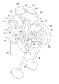
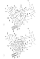
まず、図1〜図9は実施例1の可変動弁機構を示している。本機構においては、スイングアームタイプの二つのロッカアーム1が間隔をおいて並ぶように配され、各ロッカアーム1の基端部は同部に形成された凹球面部2がピボット30に支持されてなる揺動中心部となっている。ピボット30の下部の雄ネジがピボット支持部材31の雌ネジに螺入量調節可能に螺入されることにより、手動によるタペットクリアランス調整が可能となっている(これは油圧等による自動調整機構に変更することもできる。)。ロッカアーム1の先端部にはバルブ9の基端部を押圧するバルブ押圧部3が設けられている。ロッカアーム1の長さ方向の中央部には被押圧部としての被押圧ローラ4が回転可能に軸着されている。以下の説明において、便宜上、ロッカアーム1の先端方向(図1〜図8において右方向)を「前」あるいは必要に応じて前方又は前側といい、基端方向(同じく左方向)を「後」あるいは必要に応じて後方又は後側ということにする。
First, FIGS. 1-9 has shown the variable valve mechanism of Example 1. FIG. In this mechanism, two
この可変動弁機構の特徴は、ロッカアーム1の上方に、被押圧ローラ4を押圧する押圧面17を備えた揺動可能な第一介在アーム10と、制御シャフト27と、第一介在アーム10の前側方で上下に延びて制御シャフト27により上下スライド制御される第二介在アーム20とが配置されているとともに、第二介在アーム20の前側方に回転カム7が配置されていることにある。以下、これらを詳述する。
The variable valve mechanism is characterized by a swingable
第一介在アーム10は、二つのロッカアーム1に対応して間隔をおいて並んだ二つのアーム本体11と、両アーム本体11を連結する連結部12と、連結部12の前部から延びる被押動部13と、連結部12の後部から延びる突起部14とからなる。各アーム本体11は、後述する制御シャフト27に回転可能に挿通されることにより第一介在アーム10を揺動可能にする円筒形のボス部15と、各ボス部15の下側に設けられてさらに前方へ延びるアーム部16とからなる。アーム部16の下面は被押圧ローラ4を押圧する押圧面17であり、図示例の押圧面17は、その後半部が第一介在アーム10の揺動中心に対して距離が略等しい凸円弧面状の非作用面部17aであり、その前半部が第一介在アーム10の揺動中心に対して前側ほど距離が離れる作用面部17bとなっている。そして、第一介在アーム10の揺動中心は被押圧ローラ4の真上よりやや後側にあり、押圧面17は被押圧ローラ4の真上より後側からロッカアーム1の先端付近の上方まで延びている。
The
連結部12は後述する突出部28を逃がすために円筒の上半分が除去された半割円筒形に形成され、両ボス部15を連結している。被押動部13は、連結部12の前部から前下方へ延びる板状に形成され、二つのロッカアーム1間の間隔に非接触で入り込んでいる。言い換えると、第一介在アーム10は連結部12及び被押動部13の分だけロッカアーム1より幅広に形成され、第一介在アーム10のうちロッカアーム1の真上部位に押圧面17が形成され、第一介在アーム10のうちロッカアーム1の真上部位から外れた部位に被押動部13が形成されている。従って、被押動部13がロッカアーム1と干渉しないため、被押動部13の位置は押圧面17の作用面部17bより低く設定されている。図示例の被押動部13の上面は略平面であるが、曲面でもよい。突起部14は連結部12の後部から後方へ延びており、その上面にはシリンダヘッドに設けられたコイルバネ18により付勢される圧子19が当接しており、被押動部13を後述する押動部としての押動ローラ22に常に当接させるようにしている。
The connecting
制御シャフト27は、図示しない支持機構により小角度回転可能に軸支されている。制御シャフト27における二つのロッカアーム1間の間隔の上方位置には、前方へ突出する突出部28が設けられている。突出部28はその基端部においてピン29により制御シャフト27の上部に止められており、制御シャフト27と一体となって小角度回転するようになっている。なお、前記第一介在アーム10はこの小角度回転とは独立して回転自在である。制御シャフト27に対する突出部28の止め方は特に限定されないし、制御シャフト27と突出部28とが一体形成されてもよい。
The
第二介在アーム20は基端部(本例では上端部)において突出部28に回動可能に軸着され、該基端部から下方へ延びており、制御シャフト27が内燃機関の運転状況に応じて小角度(前記のとおり1回転以内の範囲)回転制御されることにより制御シャフト27と回転カム7との間で上下スライド制御される。第二介在アーム20の途中部には、回転カム7に押圧されるカム摺接部としてのカム摺接ローラ21が回転可能に軸着されている。第二介在アーム20の先端部(本例では下端部)には、第一介在アーム10の被押動部13を押動する押動部としての押動ローラ22が回転可能に軸着されている。第二介在アーム20の幅は二つのロッカアーム1間の間隔や二つのアーム本体11間の間隔よりも狭いため、第二介在アーム20の下端部はこれらの間隔に非接触で入り込んで、押動ローラ22を被押動部13に当接させる。本例では、第二介在アーム20の基端部と途中部のカム摺接部(カム摺接ローラ21)と先端部の押動部(押動ローラ22)とは、カム摺接部が回転カム7側に張り出した「く」字配置(側面視)になっている。そして、回転カム7と被押動部13と間に介在する第二介在アーム20は、上下スライドすると、回転カム7と被押動部13との距離を変えることができるように設計されている。
The
第二介在アーム20の側方には、1本のカムシャフト6が回転可能に軸支されている。カムシャフト6には、カム摺接ローラ21を側方に押圧することで、第二介在アーム20及び第一介在アーム10をその順に介してロッカアーム1を押圧することによりバルブ9をリフトさせる回転カム7が形成されている。回転カム7は、ベース円7aと、突出量が漸増するノーズ漸増部7bと、最大突出量となるノーズ7cと、突出量が漸減するノーズ漸減部7dとからなっている。回転カム7の回転方向は、ノーズ7cがカム摺接ローラ21に上方から接近する方向(図示例では反時計回り)である。そして、最上位置にある時(図7)の第二介在アーム20の上端よりも回転カム7の回転中心(カムシャフト6の軸線)が上にならないようにして、第二介在アーム20の側方に回転カム7が配置されている。
One
制御シャフト27には、制御シャフト27を内燃機関の運転状況に応じて小角度回転制御して、突出部28の配向角を1回転以内の範囲で連続的に又は段階的(少なくとも二段階、好ましくは三段階、さらに好ましくは四段階以上の多段階)に変えることにより、前記のとおり第二介在アーム20を上下スライド制御するリフト制御装置(図示略)が設けられている。第二介在アーム20が上下スライド制御されると、カム摺接ローラ21と回転カム7との接点が上下に変わると同時に、押動ローラ22が被押動部13を変位させて第一介在アーム10の揺動開始位置が変わり、もって押圧面17における被押圧ローラ4の当接位置Pが第一介在アーム10の長さ方向に変わることにより、バルブ9のリフト量、作用角及びタイミングが変化する。
The
リフト制御装置は、例えば、ヘリカルスプラインを設けたピストンが油圧により所定角の回転を伴いながら軸方向に移動し、該回転が制御シャフト27を回転させることにより突出部28の配向角を1回転以内の範囲で変える構造となっており、内燃機関の回転センサやアクセル開度センサ等からの検知値に基づいてマイクロコンピュータ等の制御装置により制御されるようになっている。リフト制御装置は、例えばステップモータ等の電動機を用いたものであってもよい。
In the lift control device, for example, a piston provided with a helical spline moves in the axial direction while rotating at a predetermined angle by hydraulic pressure, and the rotation rotates the
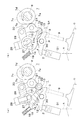
以上のように構成された可変動弁機構は、次のように作用する。
まず、図3及び図4は最大リフト量・最大作用角が必要な運転状況下を示し、図3は回転カム7のベース円7aがカム摺接ローラ21に当接するとき(いわゆるベース時)を、図4は同じくノーズ7cがカム摺接ローラ21に当接するとき(いわゆるノーズ時)をそれぞれ示している。また、各図の(a)と(b)とは断面の切断位置が異なるだけで、同じ状態を示している。この運転状況下では、制御シャフト27の小角度回転制御により突出部28が最も下側に配向し、第二介在アーム20は最下位置にスライド制御される。
The variable valve mechanism configured as described above operates as follows.
First, FIGS. 3 and 4 show an operating condition in which the maximum lift amount and the maximum operating angle are required. FIG. 3 shows the time when the
図3のベース時において、前記スライド制御によりカム摺接ローラ21と回転カム7との接点は(後述する微小リフト時(図5)との比較で)下側にあるとともに、押動ローラ22は被押動部13をその前端が二つのロッカアーム1間に進入するまで下方に押し下げている(押動ローラ22は被押動部13の前端に当接している)。このため、アーム部16は前下方へ傾いた位置にあり、これが同運転状況下における第一介在アーム10の揺動開始位置である。このとき、押圧面17における被押圧ローラ4の当接位置Pは非作用面部17aの前端部にあり、未だロッカアーム1は押し下げられないので、バルブ9のリフトは発生しない。そして、図3から図4までの間でノーズ漸増部7bがカム摺接ローラ21に当接するようになると、回転カム7がカム摺接ローラ21を押圧し始め、第二介在アーム20が上端の軸着部を中心に後方へ揺動して、押動ローラ22がコイルバネ18の付勢力に抗して被押動部13を前下方へ押動する(被押動部13における押動ローラ22の当接位置は後退する)。よって、第一介在アーム10が前下方へ揺動し始め、押圧面17における被押圧ローラ4の当接位置Pは前進して作用面部17bにかかり、ロッカアーム1はピボット30を中心として前下方へ揺動し始め、バルブ9のリフトが始まる。そして、図4のノーズ時になると、回転カム7がカム摺接ローラ21を最大に押圧し、第二介在アーム20が後方へ最大に揺動して、押動ローラ22が被押動部13を前下方へ最大に押動する(前記の通り、被押動部13とロッカアーム1とは干渉しない)。このため、第一介在アーム10は前下方へ最大に揺動し、押圧面17における被押圧ローラ4の当接位置Pは作用面部17bをさらに前進し、ロッカアーム1は前下方へ最大に揺動するため、バルブ9のリフト量Lは最大値Lmaxに達する。また、ベース時に当接位置Pは非作用面部17aの前端部にあり、第一介在アーム10が揺動し始めてから最大に揺動するまでの広い範囲でバルブ9がリフトされることから、作用角は最大となる。また、前記のとおりノーズ7cがカム摺接ローラ21に上方から接近するのに対して、カム摺接ローラ21と回転カム7との接点が下側にあることから、リフトのピークが訪れるタイミングは最も遅角となる(図9参照)。
In the base of FIG. 3, the contact between the
続いて、図5及び図6は微小リフト量・微小作用角が必要な運転状況下を示し、図5はベース時を、図6はノーズ時をそれぞれ示している。また、各図の(a)と(b)とは断面の切断位置が異なるだけで、同じ状態を示している。この運転状況下では、制御シャフト27の小角度回転制御により突出部28が図3及び図4の時よりも上側に配向し、第二介在アーム20は図3及び図4の時よりも上側の位置にスライド制御される。
Next, FIGS. 5 and 6 show operating conditions that require a minute lift amount and a minute working angle, FIG. 5 shows a base time, and FIG. 6 shows a nose time. Moreover, (a) and (b) of each figure show the same state only in the cutting position of a cross section. Under this operating condition, the projecting
図5のベース時において、前記スライド制御によりカム摺接ローラ21と回転カム7との接点は上方へ移動するとともに、押動ローラ22による被押動部13の押し下げ量が減って、被押動部13は二つのロッカアーム1より上側になる(押動ローラ22は被押動部13の前端よりやや後側に当接している)。このため、アーム部16は図3の時よりも上側に位置し、これが同運転状況下における第一介在アーム10の揺動開始位置である。このとき、押圧面17における被押圧ローラ4の当接位置Pは非作用面部17aの途中部にあり(図3の時よりも後退)、未だロッカアーム1は押し下げられないので、バルブ9のリフトは発生しない。そして、図5から図6までの間でノーズ漸増部7bがカム摺接ローラ21に当接するようになり、さらに図6のノーズ時になると、回転カム7がカム摺接ローラ21を押圧し、第二介在アーム20が後方へ揺動し、押動ローラ22が被押動部13を前下方へ押動する。よって、第一介在アーム10は前下方へ揺動するが、高い揺動開始位置からの揺動なので、図4の時よりも上側までしか揺動しない。このため、押圧面17における被押圧ローラ4の当接位置Pは作用面部17bにかかり始めたところまでしか前進しない。よって、ロッカアーム1は前下方へ僅かに揺動するにすぎず、バルブ9のリフト量は微小となる。また、ベース時に当接位置Pは非作用面部17aの途中部にあり、第一介在アーム10がある程度まで揺動してからでないとバルブ9がリフトされないことから、作用角は微小となる。また、前記のとおりノーズ7cがカム摺接ローラ21に上方から接近するのに対して、カム摺接ローラ21と回転カム7との接点が上側にあることから、リフトのピークが訪れるタイミングは最も進角となる(図9参照)。
At the base of FIG. 5, the contact between the
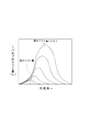
なお、図4と図6との中間的なリフト量・作用角が必要な運転状況下では、制御シャフト27の小角度回転制御により突出部28を図4と図6との中間的な位置に配向し、第二介在アーム20を図4と図6との中間的な位置に連続的に又は段階的に上下スライド制御することにより、図9に示すように中間的なリフト量・作用角・タイミングが連続的に又は段階的に得られる。
Note that, under an operating situation where an intermediate lift amount / working angle between FIGS. 4 and 6 is required, the projecting
続いて、図7及び図8はリフト休止が必要な運転状況下を示し、図7はベース時を、図8はノーズ時をそれぞれ示している。また、各図の(a)と(b)とは断面の切断位置が異なるだけで、同じ状態を示している。この運転状況下では、制御シャフト27の小角度回転制御により突出部28が図5及び図6の時よりもさらに上側に配向し、第二介在アーム20は図5及び図6の時よりもさらに上側の位置にスライド制御される。
Next, FIG. 7 and FIG. 8 show operating conditions that require lift suspension, FIG. 7 shows a base time, and FIG. 8 shows a nose time. Moreover, (a) and (b) of each figure show the same state only in the cutting position of a cross section. Under this operating condition, the small angle rotation control of the
図7のベース時において、前記スライド制御によりカム摺接ローラ21と回転カム7との接点は図5の時よりさらに上側になるとともに、押動ローラ22による被押動部13の押し下げ量が図5の時よりさらに減って、被押動部13は二つのロッカアーム1よりさらに上側になる(押動ローラ22は被押動部13の前端よりやや後側に当接している)。このため、アーム部16は図5の時よりも上側に位置し、これが同運転状況下における第一介在アーム10の揺動開始位置である。このとき、押圧面17における被押圧ローラ4の当接位置Pは非作用面部17aの途中部にあり(図5の時よりも後退)、ロッカアーム1は押し下げられないので、バルブ9のリフトは発生しない。そして、図7から図8までの間でノーズ漸増部7bがカム摺接ローラ21に当接するようになり、さらに図8のノーズ時になると、回転カム7がカム摺接ローラ21を押圧し、第二介在アーム20が後方へ揺動し、押動ローラ22が被押動部13を前下方へ押動する。よって、第一介在アーム10は前下方へ揺動するが、高い揺動開始位置からの揺動なので、図6の時よりも上側までしか揺動しない。このため、押圧面17における被押圧ローラ4の当接位置Pは非作用面部17aの前端部までしか前進しない。よって、ロッカアーム1は揺動せず、リフト休止状態となる。
At the base of FIG. 7, the contact between the
以上のように構成された本実施例の可変動弁機構によれば、従来の駆動系を大きく変えることなく、1本のカムシャフト6を回転させるだけで、バルブ9のリフト量、作用角及びタイミングを連続的又は段階的に変化させることができる。また、ロッカアーム1の上方に第一介在アーム10と上下に延びる第二介在アーム20とが配置されているとともに、第二介在アーム20の側方に回転カム7が配置されていることにより、高さを抑えたコンパクトな可変動弁機構を形成することができる。このため、可変動弁機構の車両搭載性を向上させることができる。特に本実施形態では、被押動部13の位置を押圧面17より低くして、押動ローラ22が二つのロッカアーム1間に進入できるようにしたことから、上下に延びる第二介在アーム20をより低く配置することができ、回転カム7もより低く配置しやすい。
According to the variable valve mechanism of the present embodiment configured as described above, the lift amount, the working angle, and the operating angle of the
また、押動ローラ22が被押動部13を押動する際に両部22,13の当接位置が押動方向とは交差する方向にずれるように、被押動部13が前記交差する方向に延びる略平面(又は曲面)となっており、該略平面の接線が、回転カム7の回転中心と制御シャフト27の回転中心とを結ぶ線に対して、図3〜図8に示すとおりすべての運転時において平行にならないように、具体的には33度以上になるように配向されている。なお、最小の角度である33度は、図7に示すリフト休止且つベース時に生じる。このように配向されていると、カムシャフト6と制御シャフト27との軸間ピッチをコンパクトにすることができ、車両搭載性をさらに向上させることができる。
Further, when the
なお、図10は前記第二介在アーム20の変更例を示している。この変更例の第二介在アーム20は、途中部の前面に、回転カム7に押圧されるカム摺接部としてのカム摺接チップ23が(前記カム摺接ローラ21に代えて)止着され、下端部の後面に、第一介在アーム10の被押動部13を押動する押動部としての押動チップ24が(前記押動ローラ22に代えて)止着された点においてのみ、前記第二介在アーム20と相違するものである。この変更例を用いれば、摺動抵抗が増大するものの、部品点数を減らすことができ、コストを低減することができる。
FIG. 10 shows a modification of the
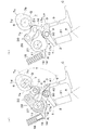
次に、図11〜図14は実施例2の可変動弁機構を示している。本実施例の可変動弁機構の特徴も、ロッカアーム1の上方に、被押圧ローラ4を押圧する押圧面を備えた揺動可能な第一介在アーム10と、制御シャフト27と、第一介在アーム10の前側方で上下に延びて制御シャフト27により上下スライド制御される第二介在アーム20とが配置されているとともに、第二介在アーム20の前側方に回転カム7が配置されていることにある。しかし、次の点においてのみ実施例1と相違している。
Next, FIGS. 11 to 14 show the variable valve mechanism of the second embodiment. The variable valve mechanism of the present embodiment is also characterized by a swingable
第一介在アーム10は、二つのアーム本体11と連結部12と被押動部13と突起部14とからなるが、各アーム本体11のアーム部16はボス部15の下側から後方へ延びている。押圧面17は、その前半部が第一介在アーム10の揺動中心に対して距離が略等しい凸円弧面状の非作用面部17aであり、その後半部が第一介在アーム10の揺動中心に対して前側ほど距離が離れる作用面部17bとなっている。連結部12は突出部28を逃がすために円筒の前半分が除去された半割円筒形に形成されている。被押動部13は、連結部12の上部から上方へ延びる板状に形成されている。突起部14は連結部12の下部から後方へ延びており、その下面にコイルバネ18により付勢される圧子19が当接している。
The
制御シャフト27には前方へ突出する突出部28が設けられているが、突出部28の位置は実施例1より下側である。第二介在アーム20は基端部(本例では下端部)において突出部28に回動可能に軸着され、該基端部から上方へ延びており、同じく上下スライド制御される。第二介在アーム20の途中部にはカム摺接ローラ21が、上端部には押動ローラ22がそれぞれ回転可能に軸着されている。
The
カムシャフト6及び回転カム7については実施例1と基本的に同じであり、第二介在アーム20の上端よりも回転カム7の回転中心が上にならないようにして、第二介在アーム20の前側方に回転カム7が配置されている。回転カム7の回転方向は、ノーズ7cがカム摺接ローラ21に下方から接近する方向(図示例では時計回り)である。
The
本実施例による作用も、各部の方向が異なるものの、基本的には実施例1と共通する。まず、図11及び図12は最大リフト量・最大作用角が必要な運転状況下を示し、図11はベース時を、図12はノーズ時をそれぞれ示している。また、各図の(a)と(b)とは断面の切断位置が異なるだけで、同じ状態を示している。この運転状況下では、制御シャフト27の小角度回転制御により突出部28が最も上側に配向し、第二介在アーム20は最上位置にスライド制御される。
The operation of this embodiment is basically the same as that of the first embodiment, although the direction of each part is different. First, FIG. 11 and FIG. 12 show operating conditions that require the maximum lift amount and maximum working angle, FIG. 11 shows the base time, and FIG. 12 shows the nose time. Moreover, (a) and (b) of each figure show the same state only in the cutting position of a cross section. Under this operating condition, the projecting
図11のベース時(実施例1の図3に相当する)において、前記スライド制御によりカム摺接ローラ21と回転カム7との接点は(後述する微小リフト時(図13)との比較で)上側にあるとともに、押動ローラ22が被押動部13を後方へ押していて、アーム部16は後下方へ傾いた位置にあり、これが同運転状況下における第一介在アーム10の揺動開始位置である。当接位置Pは非作用面部17aの前端部にあり、未だロッカアーム1は押し下げられないので、バルブ9のリフトは発生しない。そして、図11から図12までの間でノーズ漸増部7bがカム摺接ローラ21に当接するようになり、さらに図12(実施例1の図4に相当する)のノーズ時になると、回転カム7がカム摺接ローラ21を最大に押圧し、第二介在アーム20が後方へ最大に揺動して、押動ローラ22が被押動部13を後方へ最大に押動する。このため、第一介在アーム10は後下方へ最大に揺動し、当接位置Pは作用面部17bを後退し、ロッカアーム1は前下方へ最大に揺動するため、バルブ9のリフト量Lは最大値Lmaxに達する。また、作用角も最大となる。また、前記のとおりノーズ7cがカム摺接ローラ21に下方から接近するのに対して、カム摺接ローラ21と回転カム7との接点が上側にあることから、リフトのピークが訪れるタイミングは最も遅角となる(同じく図9参照)。
At the base of FIG. 11 (corresponding to FIG. 3 of the first embodiment), the contact between the
続いて、図13及び図14は微小リフト量・微小作用角が必要な運転状況下を示し、図13はベース時を、図14はノーズ時をそれぞれ示している。また、各図の(a)と(b)とは断面の切断位置が異なるだけで、同じ状態を示している。この運転状況下では、制御シャフト27の小角度回転制御により突出部28が図11及び図12の時よりも下側に配向し、第二介在アーム20は図11及び図12の時よりも下側の位置にスライド制御される。
Subsequently, FIG. 13 and FIG. 14 show operating conditions that require a minute lift amount and a minute working angle, FIG. 13 shows a base time, and FIG. 14 shows a nose time. Moreover, (a) and (b) of each figure show the same state only in the cutting position of a cross section. Under this operating condition, the projecting
図13のベース時(実施例1の図5に相当する)において、前記スライド制御によりカム摺接ローラ21と回転カム7との接点が下方へ移動するとともに、押動ローラ22による被押動部13の押し量が減って、被押動部13は前側へ変位する。このため、アーム部16は図11の時よりも上側に位置し、これが同運転状況下における第一介在アーム10の揺動開始位置である。このとき、当接位置Pは非作用面部17aの途中部にあり(図11の時よりも前進)、未だロッカアーム1は押し下げられないので、バルブ9のリフトは発生しない。そして、図13から図14までの間でノーズ漸増部7bがカム摺接ローラ21に当接するようになり、さらに図14のノーズ時(実施例1の図6に相当する)になると、回転カム7がカム摺接ローラ21を押圧し、第二介在アーム20が後方へ揺動し、押動ローラ22が被押動部13を後方へ押動する。よって、第一介在アーム10は後下方へ揺動するが、高い揺動開始位置からの揺動なので、図12の時よりも上側までしか揺動しない。また、当接位置Pは作用面部17bにかかり始めたところまでしか後退しない。このため、ロッカアーム1は前下方へ僅かに揺動し、バルブ9のリフト量は微小となる。また、作用角も微小となる。また、前記のとおりノーズ7cがカム摺接ローラ21に下方から接近するのに対して、カム摺接ローラ21と回転カム7との接点が下側にあることから、リフトのピークが訪れるタイミングは最も進角となる(同じく図9参照)。
At the base of FIG. 13 (corresponding to FIG. 5 of the first embodiment), the contact point between the
なお、図13と図14との中間的なリフト量・作用角が必要な運転状況下については、実施例1における説明を援用する。また、リフト休止が必要な運転状況下については、制御シャフト27の小角度回転制御により突出部28が図13及び図14の時よりもさらに下側に配向し、第二介在アーム20は図13及び図14の時よりもさらに上側の位置にスライド制御されることで対応するので、図13及び図14の説明と実施例1における説明とを援用する。本実施例によっても、実施例1と同様の効果を得ることができる。
In addition, about the driving | running condition in which the intermediate lift amount and working angle of FIG. 13 and FIG. 14 are required, the description in Example 1 is used. Further, under an operating condition that requires lift suspension, the projecting
また、押動ローラ22が被押動部13を押動する際に両部22,13の当接位置が押動方向とは交差する方向にずれるように、被押動部13が前記交差する方向に延びる略平面(又は曲面)となっており、該略平面の接線が、回転カム7の回転中心と制御シャフト27の回転中心とを結ぶ線に対して、図11〜図14に示すとおりすべての運転時において平行にならないように、具体的には25度以上になるように配向されている。なお、最小の角度である25度は、図13に示す微小リフト且つベース時(このときの前記角度は30度)よりも前記のとおり突出部28がさらに下側に配向して、リフト休止且つベース時となったときに生じる。
Further, when the
次に、図15は実施例3の可変動弁機構を示している。本実施例の可変動弁機構は、第一介在アーム10を軸支するシャフト32と、制御シャフト27とを別にした点においてのみ、実施例1と相違するものである。本実施例によっても、実施例1と同様の効果を得ることができる。
Next, FIG. 15 shows a variable valve mechanism of the third embodiment. The variable valve mechanism of the present embodiment is different from that of the first embodiment only in that the
まず、図16〜図23は実施例4の可変動弁機構を示している。本実施例の可変動弁機構の特徴も、実施例1、2及び3と同様に、ロッカアーム1の上方に、被押圧ローラ4を押圧する押圧面を備えた揺動可能な第一介在アーム10と、制御シャフト27と、第一介在アーム10の前側方で上下に延びて制御シャフト27により上下スライド制御される第二介在アーム20とが配置されているとともに、第二介在アーム20の前側方に回転カム7が配置されていることにある。さらに、実施例2と同様に、第一介在アーム10は、二つのロッカアーム1に対応して間隔をおいて並んだ二つのアーム本体11と、両アーム本体11を連結する連結部12と、連結部12の後部から上部に向けて延びる突出部位に備えられた被押動部とからなり、第二介在アーム20は、途中部にカム摺接ローラ21が回転可能に軸着され、上端部に押動部が形成されている。しかし、次の点においてのみ実施例2と相違している。
First, FIGS. 16 to 23 show the variable valve mechanism of the fourth embodiment. The variable valve mechanism of the present embodiment is also characterized by a swingable
第一介在アーム10の被押動部は、第一介在アーム10に回動可能に軸着された被押動ローラ40である。また、被押動ローラ40と連結部12との間の後部から後方へ膨らんだ突起部14は、その後面にはリンダヘッドに設けられたコイルバネ18により付勢される圧子19が当接しており、被押動ローラ40を後述する押動部としての押動面41に常に当接させるようにしている。
The driven portion of the
第二介在アーム20の押動部は押動面41である。この押動面41が被押動ローラ40を押動する際に両部41,40の当接位置Sが押動方向とは交差する方向にずれるように、押動面41が前記交差する方向に延びる略平面となっている。この押動面41は制御シャフト27から見ると(側面視)、制御シャフト27から遠ざかるほど被押動ローラ40の方へ向かって傾斜している。そして、この略平面の接線Xが、回転カム7の回転中心Qと制御シャフト27の回転中心Rとを結ぶ線に対してなす角度T(該線の回転カム7の回転中心Q側から始まる角度)が、すべての運転時において平行にならないように、具体的には40度以上になるように配向されている。この最小の角度を40度とすることにより、回転カム7からカム摺接ローラ21への押力による被押圧ローラ40方向への分力をより大きくすることになり、第二介在アーム20の押し下げ力の伝達の効率化を図ることができる。また、回転カム7からカム摺接ローラ21への押力による突出部28方向への分力をより小さくすることができるため、制御シャフト27の駆動軸に対する負荷の軽減を図ることもできる。なお、該角度は、被押圧ローラ40が押し下げられる際のピボット支持部材31等による物理的制限及び最大可変リフト量により制限される。
The pushing portion of the
本実施例による作用も、各部の方向が異なるものの、基本的には実施例1及び実施例2と共通する。従って、共通する部分については前記説明を援用し、異なる部分について説明する。まず、図18及び図19は最大リフト量・最大作用角が必要な運転状況下を示し、図18はベース時を、図19はノーズ時をそれぞれ示している。また、各図の(a)と(b)とは断面の切断位置が異なるだけで、同じ状態を示している。
The operation of this embodiment is basically the same as that of
図18のベース時(実施例2の図11に相当する)において、前記スライド制御によりカム摺接ローラ21と回転カム7との接点は(後述する微小リフト時(図20)との比較で)上側にあるとともに、押動面41が被押動ローラ40を後方へ押していて(被押動ローラ40は押動面41の下端に当接している)、アーム部16は後下方へ傾いた位置にあり、これが同運転状況下における第一介在アーム10の揺動開始位置である。この時、押動面41の接線Xが回転中心Q,Rを結ぶ線に対してなす角度Tは約71度である。
At the base of FIG. 18 (corresponding to FIG. 11 of the second embodiment), the contact between the
そして、図18から図19までの間で、押動面41がコイルバネ18の付勢力に抗して被押動ローラ40を後方へ押動しながら、押動面41が押動方向とは交差する方向にずれ(被押動部13における押動ローラ22の当接位置Sはずれながら後退する)、バルブ9のリフトが始まる。そして、図19のノーズ時(実施例2の図12に相当する)になると、回転カム7がカム摺接ローラ21を最大に押圧し、第二介在アーム20が後方へ最大に揺動して、押動面41が被押動ローラ40を後方へ最大に押動し、ロッカアーム1は前下方へ最大に揺動するため、バルブ9のリフト量Lは最大値Lmaxに達する。この時、押動面41の接線Xが回転中心Q,Rを結ぶ線に対してなす角度Tは約88度である。また、前記のとおりノーズ7cがカム摺接ローラ21に下方から接近するのに対して、カム摺接ローラ21と回転カム7との接点が上側にあることから、リフトのピークが訪れるタイミングは最も遅角となる(同じく図9参照)。
Then, between FIG. 18 and FIG. 19, the pushing
続いて、図20及び図21は微小リフト量・微小作用角が必要な運転状況下を示し、図20はベース時を、図21はノーズ時をそれぞれ示している。また、各図の(a)と(b)とは断面の切断位置が異なるだけで、同じ状態を示している。この運転状況下では、制御シャフト27の小角度回転制御により突出部28が図18及び図19の時よりも下側に配向し、第二介在アーム20は図18及び図19の時よりも下側の位置にスライド制御される。
Next, FIG. 20 and FIG. 21 show operating conditions that require a minute lift amount and minute working angle, FIG. 20 shows a base time, and FIG. 21 shows a nose time. Moreover, (a) and (b) of each figure show the same state only in the cutting position of a cross section. Under this operating condition, the projecting
図20のベース時(実施例2の図13に相当する)において、前記スライド制御によりカム摺接ローラ21と回転カム7との接点は下方へ移動するとともに、押動面41による被押動ローラ40の押し下げ量が減って、被押動ローラ40は前側へ変位する。このため、アーム部16は図18の時よりも上側に位置し、これが同運転状況下における第一介在アーム10の揺動開始位置である。この時、押動面41の接線Xが回転中心Q,Rを結ぶ線に対してなす角度Tは約45度である。
At the base of FIG. 20 (corresponding to FIG. 13 of the second embodiment), the contact point between the
そして、図20から図21までの間でノーズ漸増部7bがカム摺接ローラ21に当接するようになり、さらに図21のノーズ時(実施例2の図14に相当する)になると、回転カム7がカム摺接ローラ21を押圧し、第二介在アーム20が後方へ揺動し、押動面41が被押動ローラ40を後方へ押動しながら、両部の当接位置Sが押動方向とは交差する方向にずれる。よって、第一介在アーム10は後下方へ揺動するが、高い揺動開始位置からの揺動なので、図19の時よりも上側までしか揺動しないので、作用角は微小となる。この時、押動面41の接線Xが回転中心Q,Rを結ぶ線に対してなす角度Tは約68度である。また、前記のとおりノーズ7cがカム摺接ローラ21に下方から接近するのに対して、カム摺接ローラ21と回転カム7との接点が下側にあることから、リフトのピークが訪れるタイミングは最も進角となる(同じく図9参照)。
20 to 21, the nose gradually increasing
なお、図19と図21との中間的なリフト量・作用角が必要な運転状況下については、実施例1及び実施例2における説明を援用する。また、リフト休止が必要な運転状況下については、図22及び図23に示すように、制御シャフト27の小角度回転制御により突出部28が図20及び図21の時よりもさらに下側に配向し、第二介在アーム20は図20及び図21の時よりもさらに下側の位置にスライド制御されることで対応するので、図20及び図21の説明と実施例1における説明とを援用する。この時、押動面41の接線Xが回転中心Q,Rを結ぶ線に対してなす角度Tは、ベース時には約40度であり、ノーズ時には約62度である。本実施例によっても、実施例2と同様の効果を得ることができる。
In addition, about the driving | running condition in which the intermediate lift amount and working angle of FIG. 19 and FIG. 21 are required, the description in Example 1 and Example 2 is used. Further, under an operating condition that requires a lift stop, as shown in FIGS. 22 and 23, the projecting
次に、図24〜図27は実施例5の可変動弁機構を示している。本実施例の可変動弁機構の特徴も、実施例1、2,3及び4と同様に、ロッカアーム1の上方に、被押圧ローラ4を押圧する押圧面を備えた揺動可能な第一介在アーム10と、制御シャフト27と、第一介在アーム10の前側方で上下に延びて制御シャフト27により上下スライド制御される第二介在アーム20とが配置されているとともに、第二介在アーム20の前側方に回転カム7が配置されていることにある。さらに、実施例1と同様に、第一介在アーム10は、二つのロッカアーム1に対応して間隔をおいて並んだ二つのアーム本体11と、両アーム本体11を連結する連結部12と、連結部12の後部から下部に向けて延びる突出部位に備えられた被押動部とからなり、第二介在アーム20は、途中部にカム摺接ローラ21が回転可能に軸着され、下端部に押動部が形成されている。しかし、次の点においてのみ実施例1と相違している。
Next, FIGS. 24 to 27 show the variable valve mechanism of the fifth embodiment. As in the first, second, third and fourth embodiments, the variable valve mechanism of the present embodiment is also characterized by a swingable first intervention provided with a pressing surface for pressing the
第一介在アーム10の被押動部は、第一介在アーム10に回動可能に軸着された被押動ローラ40である。また、第二介在アーム20の押動部は押動面41である。この押動面41が被押動ローラ40を押動する際に両部41,40の当接位置Sが押動方向とは交差する方向にずれるように、押動面41が前記交差する方向に延びる略平面となっている。この押動面41は制御シャフト27から見ると(側面視)、制御シャフト27から遠ざかるほど被押動ローラ40の方へ向かって傾斜している。そして、この略平面の接線Xが、回転カム7の回転中心Qと制御シャフト27の回転中心Rとを結ぶ線に対してなす角度Tが、すべての運転時において平行にならないように、具体的には40度以上になるように配向されている。
The driven portion of the
本実施例による作用も、各部の方向が異なるものの、基本的には実施例1と共通する。まず、図24及び図25は最大リフト量・最大作用角が必要な運転状況下を示し、図24はベース時を、図25はノーズ時をそれぞれ示している。また、各図の(a)と(b)とは断面の切断位置が異なるだけで、同じ状態を示している。この運転状況下では、制御シャフト27の小角度回転制御により突出部28が最も下側に配向し、第二介在アーム20は最下位置にスライド制御される。
The operation of this embodiment is basically the same as that of the first embodiment, although the direction of each part is different. First, FIG. 24 and FIG. 25 show operating conditions that require the maximum lift amount and maximum working angle, FIG. 24 shows the base time, and FIG. 25 shows the nose time. Moreover, (a) and (b) of each figure show the same state only in the cutting position of a cross section. Under this operating condition, the projecting
図24のベース時(実施例1の図3に相当する)において、前記スライド制御によりカム摺接ローラ21と回転カム7との接点は(後述する微小リフト時(図26)との比較で)上側にあるとともに、前記の通り、被押動ローラ40とロッカアーム1とは干渉しないので、押動面41は被押動ローラ40を二つのロッカアーム1間に進入するまで下方に押し下げている(被押動ローラ40は押動面41の略上端に当接している)。アーム部16は前上方へ傾いた位置にあり、これが同運転状況下における第一介在アーム10の揺動開始位置である。この時、押動面41の接線Xが回転中心Q,Rを結ぶ線に対してなす角度Tは約71度である。
At the base of FIG. 24 (corresponding to FIG. 3 of the first embodiment), the contact between the
そして、図24から図25までの間でノーズ漸増部7bがカム摺接ローラ21に当接するようになり、押動面41がコイルバネ18の付勢力に抗して被押動ローラ40を後方へ押動しながら、押動面41が押動方向とは交差する方向にずれ(被押動部13における押動ローラ22の当接位置Sはずれながら後退する)、バルブ9のリフトが始まる。そして、図25(実施例1の図4に相当する)のノーズ時になると、回転カム7がカム摺接ローラ21を最大に押圧し、第二介在アーム20が前方へ最大に揺動して、押動面41が被押動ローラ40を前方へ最大に押動すし、ロッカアーム1は前下方へ最大に揺動するため、バルブ9のリフト量Lは最大値Lmaxに達する。この時、押動面41の接線Xが回転中心Q,Rを結ぶ線に対してなす角度Tは約89度である。また、前記のとおりノーズ7cがカム摺接ローラ21に上方から接近するのに対して、カム摺接ローラ21と回転カム7との接点が下側にあることから、リフトのピークが訪れるタイミングは最も遅角となる(同じく図9参照)。
24 to 25, the nose gradually increasing
続いて、図26及び図27は微小リフト量・微小作用角が必要な運転状況下を示し、図26はベース時を、図27はノーズ時をそれぞれ示している。また、各図の(a)と(b)とは断面の切断位置が異なるだけで、同じ状態を示している。この運転状況下では、制御シャフト27の小角度回転制御により突出部28が図24及び図25の時よりも上側に配向し、第二介在アーム20は図24及び図25の時よりも上側の位置にスライド制御される。
Next, FIG. 26 and FIG. 27 show operating conditions that require a minute lift amount and a minute working angle, FIG. 26 shows a base time, and FIG. 27 shows a nose time. Moreover, (a) and (b) of each figure show the same state only in the cutting position of a cross section. Under this operating condition, the projecting
図26のベース時(実施例1の図5に相当する)において、前記スライド制御によりカム摺接ローラ21と回転カム7との接点が上方へ移動するとともに、押動面41による被押動ローラ40の押し量が減って、被押動ローラ40は二つのロッカアーム1より上側になる(被押動ローラ40は押動面41の上端よりやや下側に当接している)。このため、アーム部16は図24の時よりも上側に位置し、これが同運転状況下における第一介在アーム10の揺動開始位置である。この時、押動面41の接線Xが回転中心Q,Rを結ぶ線に対してなす角度Tは約45度である。
26 (corresponding to FIG. 5 in the first embodiment), the contact point between the
そして、図26から図27までの間でノーズ漸増部7bがカム摺接ローラ21に当接するようになり、さらに図26のノーズ時(実施例1の図6に相当する)になると、回転カム7がカム摺接ローラ21を押圧し、第二介在アーム20が後方へ揺動し、押動面41が被押動ローラ40を後方へ押動しながら、両部の当接位置Sが押動方向とは交差する方向にずれる。よって、第一介在アーム10は前下方へ揺動するが、高い揺動開始位置からの揺動なので、図25の時よりも上側までしか揺動しないので、作用角は微小となる。この時、押動面41の接線Xが回転中心Q,Rを結ぶ線に対してなす角度Tは約68度である。また、前記のとおりノーズ7cがカム摺接ローラ21に上方から接近するのに対して、カム摺接ローラ21と回転カム7との接点が下側にあることから、リフトのピークが訪れるタイミングは最も進角となる(同じく図9参照)。
26 to 27, the nose gradually increasing
なお、図25と図27との中間的なリフト量・作用角が必要な運転状況下については、実施例1及び実施例2における説明を援用する。また、リフト休止が必要な運転状況下については、制御シャフト27の小角度回転制御により突出部28が図26及び図27の時よりもさらに上側に配向し、第二介在アーム20は図26及び図27の時よりもさらに上側の位置にスライド制御されることで対応するので、図15及び図27の説明と実施例1における説明とを援用する。本実施例によっても、実施例1と同様の効果を得ることができる。
In addition, about the driving | running condition which requires the intermediate lift amount and working angle of FIG. 25 and FIG. 27, the description in Example 1 and Example 2 is used. Further, under an operating condition that requires a lift stop, the projecting
なお、本発明は前記実施形態の構成に限定されるものではなく、例えば次のように、発明の趣旨から逸脱しない範囲で変更して具体化することもできる。
(1)リフト制御装置の構成や制御の仕方を適宜変更すること。
(2)中央部に揺動中心部があるロッカアームとすること。
(3)第二介在アーム20の形状を適宜変更すること。
(4)押圧面17の形状を適宜変更すること。
In addition, this invention is not limited to the structure of the said embodiment, For example, as follows, it can also change and actualize in the range which does not deviate from the meaning of invention.
(1) Change the configuration and control method of the lift control device as appropriate.
(2) Use a rocker arm with a rocking center at the center.
(3) Change the shape of the
(4) Change the shape of the
1 ロッカアーム
4 被押圧ローラ
6 カムシャフト
7 回転カム
9 バルブ
10 第一介在アーム
13 被押動部
16 アーム部
17 押圧面
20 第二介在アーム
21 カム摺接ローラ
22 押動ローラ
27 制御シャフト
28 突出部
40 被押動ローラ
41 押動面
DESCRIPTION OF
Claims (10)
前記第二介在アーム(20)は、その基端部において制御シャフト(27)の突出部(28)に回動可能に軸着され、前記制御シャフト(27)が内燃機関の運転状況に応じて回転制御されることにより前記第二介在アーム(20)が上下スライド制御され、
前記第二介在アーム(20)は前記基端部から下方へ延び、その途中部に前記回転カム(7)に押圧されるカム摺接部(21,23)を備え、その下端部に前記第一介在アーム(10)の被押動部(13,40)を押動する押動部(22,24,41)を備え、
前記第一介在アーム(10)は、前記制御シャフト(27)に該制御シャフトの回転とは独立して揺動可能に軸着され、
前記第一介在アーム(10)は前記ロッカアーム(1)より幅広に形成され、前記第一介在アーム(10)のうち前記ロッカアーム(1)の真上位置に前記押圧面(17)が形成され、前記第一介在アーム(10)のうち前記ロッカアーム(1)の真上部位から外れた位置に前記被押動部(13,40)が形成された可変動弁機構。 Above the rocker arm (1), a swingable first intervening arm (10) having a pressing surface (17) for pressing the pressed portion (4) of the rocker arm (1), and the first interposing arm (10 ) And a second intervening arm (20) that extends vertically and is controlled to slide up and down according to the operating condition of the internal combustion engine, and on the side of the second interposing arm (20), A rotating cam (7) that presses the rocker arm (1) through the second intervening arm (20) and the first intervening arm (10) in that order is disposed.
The second intervening arm (20) is pivotally attached to the projecting portion (28) of the control shaft (27) at the base end thereof, and the control shaft (27) depends on the operating condition of the internal combustion engine. The second interposed arm (20) is controlled to slide up and down by being controlled in rotation.
The second intervening arm (20) includes a cam sliding contact portion (21, 23) that is pressed downward from the base end portion and is pressed against the rotating cam (7), and has a lower end portion that includes the first interposing arm (20). Provided with pushing parts (22, 24, 41) for pushing the pushed parts (13, 40) of one intervening arm (10);
The first intervening arm (10) is pivotally attached to the control shaft (27) so as to be swingable independently of the rotation of the control shaft ,
The first intervening arm (10) is formed wider than the rocker arm (1), and the pressing surface (17) is formed at a position directly above the rocker arm (1) of the first intervening arm (10). A variable valve mechanism in which the pushed portion (13, 40) is formed at a position deviated from a position directly above the rocker arm (1) in the first intervening arm (10) .
前記第二介在アーム(20)は、その基端部において制御シャフト(27)の突出部(28)に回動可能に軸着され、前記制御シャフト(27)が内燃機関の運転状況に応じて回転制御されることにより前記第二介在アーム(20)が上下スライド制御され、
前記第二介在アーム(20)は前記基端部から上方へ延び、その途中部に前記回転カム(7)に押圧されるカム摺接部(21,23)を備え、その上端部に前記第一介在アーム(10)の被押動部(13,40)を押動する押動部(22,24,41)を備えた可変動弁機構。 Above the rocker arm (1), a swingable first intervening arm (10) having a pressing surface (17) for pressing the pressed portion (4) of the rocker arm (1), and the first interposing arm (10 ) And a second intervening arm (20) that extends vertically and is controlled to slide up and down according to the operating condition of the internal combustion engine, and on the side of the second interposing arm (20), A rotating cam (7) that presses the rocker arm (1) through the second intervening arm (20) and the first intervening arm (10) in that order is disposed.
The second intervening arm (20) is pivotally attached to the projecting portion (28) of the control shaft (27) at the base end thereof, and the control shaft (27) depends on the operating condition of the internal combustion engine. The second interposed arm (20) is controlled to slide up and down by being controlled in rotation.
The second intervening arm (20) extends upward from the base end portion, and includes a cam slide contact portion (21, 23) pressed against the rotating cam (7) in the middle portion thereof, and the upper end portion thereof A variable valve mechanism provided with a pushing portion (22, 24, 41) for pushing the pushed portion (13, 40) of one intervening arm (10) .
前記第二介在アーム(20)は、その基端部において制御シャフト(27)の突出部(28)に回動可能に軸着され、前記制御シャフト(27)が内燃機関の運転状況に応じて回転制御されることにより前記第二介在アーム(20)が上下スライド制御され、
前記第二介在アーム(20)は前記基端部から下方又は上方へ延び、その途中部に前記回転カム(7)に押圧されるカム摺接部(21,23)を備え、その先端部に前記第一介在アーム(10)の被押動部(13,40)を押動する押動部(22,24,41)を備え、
前記第一介在アーム(10)は、前記制御シャフト(27)に該制御シャフトの回転とは独立して揺動可能に軸着され、
前記第二介在アーム(20)が上下スライド制御されることにより、前記第二介在アーム(20)と前記回転カム(7)との接点が上下に変わるとともに、前記第一介在アーム(10)の揺動開始位置が変わり、もって前記押圧面(17)における前記被押圧部(4)の当接位置が前記押圧面(17)の長さ方向に変わることにより、バルブ(9)のリフト量、作用角及びタイミングが変化する可変動弁機構。 Above the rocker arm (1), a swingable first intervening arm (10) having a pressing surface (17) for pressing the pressed portion (4) of the rocker arm (1), and the first interposing arm (10 ) And a second intervening arm (20) that extends vertically and is controlled to slide up and down according to the operating condition of the internal combustion engine, and on the side of the second interposing arm (20), A rotating cam (7) that presses the rocker arm (1) through the second intervening arm (20) and the first intervening arm (10) in that order is disposed.
The second intervening arm (20) is pivotally attached to the projecting portion (28) of the control shaft (27) at the base end thereof, and the control shaft (27) depends on the operating condition of the internal combustion engine. The second interposed arm (20) is controlled to slide up and down by being controlled in rotation.
The second intervening arm (20) extends downward or upward from the base end portion, and is provided with a cam sliding contact portion (21, 23) pressed against the rotating cam (7) in the middle portion thereof, at the distal end portion thereof. Provided with pushing parts (22, 24, 41) for pushing the pushed parts (13, 40) of the first intervening arm (10);
The first intervening arm (10) is pivotally attached to the control shaft (27) so as to be swingable independently of the rotation of the control shaft,
When the second intervening arm (20) is controlled to slide up and down, the contact point between the second intervening arm (20) and the rotating cam (7) changes up and down, and the first intervening arm (10) Since the swing start position is changed, and the contact position of the pressed portion (4) on the pressing surface (17) is changed in the length direction of the pressing surface (17), the lift amount of the valve (9), Variable valve mechanism with variable working angle and timing .
前記第二介在アーム(20)は、その基端部において制御シャフト(27)の突出部(28)に回動可能に軸着され、前記制御シャフト(27)が内燃機関の運転状況に応じて回転制御されることにより前記第二介在アーム(20)が上下スライド制御され、
前記第二介在アーム(20)は前記基端部から下方又は上方へ延び、その途中部に前記回転カム(7)に押圧されるカム摺接部(21,23)を備え、その先端部に前記第一介在アーム(10)の被押動部(13,40)を押動する押動部(22,24,41)を備え、
前記第一介在アーム(10)は、前記制御シャフト(27)に該制御シャフトの回転とは独立して揺動可能に軸着され、
前記被押動部(13)が前記押動部(22,24,41)に常に当接するように前記第一介在アーム(10)を付勢する付勢手段(18)が設けられた可変動弁機構。 Above the rocker arm (1), a swingable first intervening arm (10) having a pressing surface (17) for pressing the pressed portion (4) of the rocker arm (1), and the first interposing arm (10 ) And a second intervening arm (20) that extends vertically and is controlled to slide up and down according to the operating condition of the internal combustion engine, and on the side of the second interposing arm (20), A rotating cam (7) that presses the rocker arm (1) through the second intervening arm (20) and the first intervening arm (10) in that order is disposed.
The second intervening arm (20) is pivotally attached to the projecting portion (28) of the control shaft (27) at the base end thereof, and the control shaft (27) depends on the operating condition of the internal combustion engine. The second interposed arm (20) is controlled to slide up and down by being controlled in rotation.
The second intervening arm (20) extends downward or upward from the base end portion, and is provided with a cam sliding contact portion (21, 23) pressed against the rotating cam (7) in the middle portion thereof, at the distal end portion thereof. Provided with pushing parts (22, 24, 41) for pushing the pushed parts (13, 40) of the first intervening arm (10);
The first intervening arm (10) is pivotally attached to the control shaft (27) so as to be swingable independently of the rotation of the control shaft,
A variable motion provided with a biasing means (18) for biasing the first intervening arm (10) so that the pushed portion (13) is always in contact with the pushing portion (22, 24, 41). Valve mechanism.
前記第二介在アーム(20)は、その基端部において制御シャフト(27)の突出部(28)に回動可能に軸着され、前記制御シャフト(27)が内燃機関の運転状況に応じて回転制御されることにより前記第二介在アーム(20)が上下スライド制御され、
前記第二介在アーム(20)は前記基端部から下方又は上方へ延び、その途中部に前記回転カム(7)に押圧されるカム摺接部(21,23)を備え、その先端部に前記第一介在アーム(10)の被押動部(13,40)を押動する押動部(22,24,41)を備え、
前記第一介在アーム(10)は、前記制御シャフト(27)に該制御シャフトの回転とは独立して揺動可能に軸着され、
前記押動部(22,24,41)が前記被押動部(13,40)を押動する際に両部(22,24,41)(13,40)の当接位置(S)が押動方向とは交差する方向にずれるように、両部(22,24,41)(13,40)のいずれか一方が前記交差する方向に延びる略平面又は曲面となっており、該略平面又は曲面(曲面の場合はその中央部)の接線(X)が、前記回転カム(7)の回転中心(Q)と制御シャフト(27)の回転中心(R)とを結ぶ線に対して、すべての運転時において平行にならないように配向されている可変動弁機構。 Above the rocker arm (1), a swingable first intervening arm (10) having a pressing surface (17) for pressing the pressed portion (4) of the rocker arm (1), and the first interposing arm (10 ) And a second intervening arm (20) that extends vertically and is controlled to slide up and down according to the operating condition of the internal combustion engine, and on the side of the second interposing arm (20), A rotating cam (7) that presses the rocker arm (1) through the second intervening arm (20) and the first intervening arm (10) in that order is disposed.
The second intervening arm (20) is pivotally attached to the projecting portion (28) of the control shaft (27) at the base end thereof, and the control shaft (27) depends on the operating condition of the internal combustion engine. The second interposed arm (20) is controlled to slide up and down by being controlled in rotation.
The second intervening arm (20) extends downward or upward from the base end portion, and is provided with a cam sliding contact portion (21, 23) pressed against the rotating cam (7) in the middle portion thereof, at the distal end portion thereof. Provided with pushing parts (22, 24, 41) for pushing the pushed parts (13, 40) of the first intervening arm (10);
The first intervening arm (10) is pivotally attached to the control shaft (27) so as to be swingable independently of the rotation of the control shaft,
When the pushing parts (22, 24, 41) push the pushed parts (13, 40), the contact positions (S) of both parts (22, 24, 41) (13, 40) are Either one of the two parts (22, 24, 41) (13, 40) is a substantially flat surface or a curved surface extending in the intersecting direction so as to deviate in the direction intersecting the pushing direction. Alternatively, the tangent (X) of the curved surface (the center in the case of a curved surface) is connected to the line connecting the rotation center (Q) of the rotating cam (7) and the rotation center (R) of the control shaft (27). A variable valve mechanism that is oriented so that it is not parallel during all operations .
前記第二介在アーム(20)は、その基端部において制御シャフト(27)の突出部(28)に回動可能に軸着され、前記制御シャフト(27)が内燃機関の運転状況に応じて回転制御されることにより前記第二介在アーム(20)が上下スライド制御され、The second intervening arm (20) is pivotally attached to the projecting portion (28) of the control shaft (27) at the base end thereof, and the control shaft (27) depends on the operating condition of the internal combustion engine. The second interposed arm (20) is controlled to slide up and down by being controlled in rotation.
前記第二介在アーム(20)は前記基端部から下方又は上方へ延び、その途中部に前記回転カム(7)に押圧されるカム摺接部(21,23)を備え、その先端部に前記第一介在アーム(10)の被押動部(13,40)を押動する押動部(22,24,41)を備え、The second intervening arm (20) extends downward or upward from the base end portion, and is provided with a cam sliding contact portion (21, 23) pressed against the rotating cam (7) in the middle portion thereof, at the distal end portion thereof. Provided with pushing parts (22, 24, 41) for pushing the pushed parts (13, 40) of the first intervening arm (10);
前記第一介在アーム(10)は、前記制御シャフト(27)に該制御シャフトの回転とは独立して揺動可能に軸着され、The first intervening arm (10) is pivotally attached to the control shaft (27) so as to be swingable independently of the rotation of the control shaft,
前記押動部(41)は、前記スライド制御時に前記被押動部(40)に対して摺動可能に構成され、前記被押動部(40)がローラ形状である可変動弁機構。The variable pushing mechanism (41) is configured such that the pushing portion (41) is slidable with respect to the pushed portion (40) during the slide control, and the pushed portion (40) has a roller shape.
Priority Applications (1)
| Application Number | Priority Date | Filing Date | Title |
|---|---|---|---|
| JP2004171582A JP4268094B2 (en) | 2003-06-13 | 2004-06-09 | Variable valve mechanism |
Applications Claiming Priority (2)
| Application Number | Priority Date | Filing Date | Title |
|---|---|---|---|
| JP2003169676 | 2003-06-13 | ||
| JP2004171582A JP4268094B2 (en) | 2003-06-13 | 2004-06-09 | Variable valve mechanism |
Publications (3)
| Publication Number | Publication Date |
|---|---|
| JP2005023933A JP2005023933A (en) | 2005-01-27 |
| JP2005023933A5 JP2005023933A5 (en) | 2006-12-21 |
| JP4268094B2 true JP4268094B2 (en) | 2009-05-27 |
Family
ID=34197075
Family Applications (1)
| Application Number | Title | Priority Date | Filing Date |
|---|---|---|---|
| JP2004171582A Expired - Fee Related JP4268094B2 (en) | 2003-06-13 | 2004-06-09 | Variable valve mechanism |
Country Status (1)
| Country | Link |
|---|---|
| JP (1) | JP4268094B2 (en) |
Families Citing this family (6)
| Publication number | Priority date | Publication date | Assignee | Title |
|---|---|---|---|---|
| JP4616840B2 (en) | 2004-10-06 | 2011-01-19 | シチズンホールディングス株式会社 | printer |
| JP4539430B2 (en) * | 2005-05-11 | 2010-09-08 | トヨタ自動車株式会社 | Variable valve gear |
| JP4507997B2 (en) * | 2005-06-15 | 2010-07-21 | 三菱自動車工業株式会社 | Variable valve operating device for internal combustion engine |
| JP5115748B2 (en) * | 2009-02-13 | 2013-01-09 | スズキ株式会社 | Variable valve operating device for internal combustion engine |
| JP5767790B2 (en) * | 2010-07-28 | 2015-08-19 | 株式会社オティックス | Valve gear |
| JP7368281B2 (en) * | 2020-03-11 | 2023-10-24 | 株式会社オティックス | Internal combustion engine variable valve mechanism |
-
2004
- 2004-06-09 JP JP2004171582A patent/JP4268094B2/en not_active Expired - Fee Related
Also Published As
| Publication number | Publication date |
|---|---|
| JP2005023933A (en) | 2005-01-27 |
Similar Documents
| Publication | Publication Date | Title |
|---|---|---|
| JP2558031B2 (en) | Cam mechanism | |
| JP4108295B2 (en) | Variable valve mechanism | |
| US7469669B2 (en) | Variable valve train mechanism of internal combustion engine | |
| US7299775B2 (en) | Variable valve operating device | |
| JP4362249B2 (en) | Variable valve mechanism | |
| CA2537162A1 (en) | Valve mechanism for an internal combustion engine | |
| JP4268094B2 (en) | Variable valve mechanism | |
| JP4093849B2 (en) | Variable valve mechanism | |
| JP4143012B2 (en) | Variable valve mechanism | |
| JP4063622B2 (en) | Variable valve mechanism | |
| JP4205595B2 (en) | Variable valve mechanism | |
| JP4220922B2 (en) | Variable valve mechanism | |
| JP4289193B2 (en) | Variable valve gear for engine | |
| JP4220911B2 (en) | Variable valve mechanism | |
| JP4063623B2 (en) | Variable valve mechanism | |
| JP4084671B2 (en) | Variable valve mechanism | |
| JP4345616B2 (en) | Variable valve gear for engine | |
| JP4063587B2 (en) | Variable valve mechanism | |
| JP4108293B2 (en) | Variable valve mechanism | |
| JP2008025441A (en) | Variable valve gear | |
| JP4185869B2 (en) | Variable valve mechanism | |
| JP4128086B2 (en) | Variable valve mechanism | |
| JP4546435B2 (en) | Variable lift valve operating system for internal combustion engine | |
| JP4010879B2 (en) | Variable valve mechanism | |
| JP5188155B2 (en) | Variable valve operating device for internal combustion engine |
Legal Events
| Date | Code | Title | Description |
|---|---|---|---|
| A521 | Written amendment |
Free format text: JAPANESE INTERMEDIATE CODE: A523 Effective date: 20061101 |
|
| A621 | Written request for application examination |
Free format text: JAPANESE INTERMEDIATE CODE: A621 Effective date: 20061101 |
|
| A977 | Report on retrieval |
Free format text: JAPANESE INTERMEDIATE CODE: A971007 Effective date: 20080730 |
|
| A131 | Notification of reasons for refusal |
Free format text: JAPANESE INTERMEDIATE CODE: A131 Effective date: 20080805 |
|
| A521 | Written amendment |
Free format text: JAPANESE INTERMEDIATE CODE: A523 Effective date: 20081003 |
|
| A131 | Notification of reasons for refusal |
Free format text: JAPANESE INTERMEDIATE CODE: A131 Effective date: 20081104 |
|
| A521 | Written amendment |
Free format text: JAPANESE INTERMEDIATE CODE: A523 Effective date: 20081226 |
|
| TRDD | Decision of grant or rejection written | ||
| A01 | Written decision to grant a patent or to grant a registration (utility model) |
Free format text: JAPANESE INTERMEDIATE CODE: A01 Effective date: 20090203 |
|
| A01 | Written decision to grant a patent or to grant a registration (utility model) |
Free format text: JAPANESE INTERMEDIATE CODE: A01 |
|
| A61 | First payment of annual fees (during grant procedure) |
Free format text: JAPANESE INTERMEDIATE CODE: A61 Effective date: 20090219 |
|
| R150 | Certificate of patent or registration of utility model |
Free format text: JAPANESE INTERMEDIATE CODE: R150 |
|
| FPAY | Renewal fee payment (event date is renewal date of database) |
Free format text: PAYMENT UNTIL: 20120227 Year of fee payment: 3 |
|
| FPAY | Renewal fee payment (event date is renewal date of database) |
Free format text: PAYMENT UNTIL: 20120227 Year of fee payment: 3 |
|
| FPAY | Renewal fee payment (event date is renewal date of database) |
Free format text: PAYMENT UNTIL: 20130227 Year of fee payment: 4 |
|
| FPAY | Renewal fee payment (event date is renewal date of database) |
Free format text: PAYMENT UNTIL: 20130227 Year of fee payment: 4 |
|
| FPAY | Renewal fee payment (event date is renewal date of database) |
Free format text: PAYMENT UNTIL: 20140227 Year of fee payment: 5 |
|
| R250 | Receipt of annual fees |
Free format text: JAPANESE INTERMEDIATE CODE: R250 |
|
| R250 | Receipt of annual fees |
Free format text: JAPANESE INTERMEDIATE CODE: R250 |
|
| R250 | Receipt of annual fees |
Free format text: JAPANESE INTERMEDIATE CODE: R250 |
|
| LAPS | Cancellation because of no payment of annual fees |