JP4265986B2 - Image processing method, apparatus, and program - Google Patents
Image processing method, apparatus, and program Download PDFInfo
- Publication number
- JP4265986B2 JP4265986B2 JP2004082804A JP2004082804A JP4265986B2 JP 4265986 B2 JP4265986 B2 JP 4265986B2 JP 2004082804 A JP2004082804 A JP 2004082804A JP 2004082804 A JP2004082804 A JP 2004082804A JP 4265986 B2 JP4265986 B2 JP 4265986B2
- Authority
- JP
- Japan
- Prior art keywords
- frame image
- feature amount
- image
- target
- correction value
- Prior art date
- Legal status (The legal status is an assumption and is not a legal conclusion. Google has not performed a legal analysis and makes no representation as to the accuracy of the status listed.)
- Expired - Fee Related
Links
- 238000003672 processing method Methods 0.000 title claims description 26
- 238000012937 correction Methods 0.000 claims description 347
- 238000004364 calculation method Methods 0.000 claims description 108
- 238000000034 method Methods 0.000 claims description 45
- 230000008859 change Effects 0.000 claims description 32
- 230000008569 process Effects 0.000 claims description 24
- 238000009499 grossing Methods 0.000 claims description 22
- 230000009467 reduction Effects 0.000 description 11
- 238000010586 diagram Methods 0.000 description 7
- 230000007704 transition Effects 0.000 description 7
- 238000001914 filtration Methods 0.000 description 5
- 238000003384 imaging method Methods 0.000 description 5
- 238000012935 Averaging Methods 0.000 description 4
- 230000003247 decreasing effect Effects 0.000 description 3
- 230000000694 effects Effects 0.000 description 3
- 230000007423 decrease Effects 0.000 description 2
- 238000005429 filling process Methods 0.000 description 2
- 238000003702 image correction Methods 0.000 description 2
- 230000008901 benefit Effects 0.000 description 1
- 230000006872 improvement Effects 0.000 description 1
Images


Description
本発明は、動画像の画質を補正する画像処理方法および装置並びにそのためのプログラムに関するものである。 The present invention relates to an image processing method and apparatus for correcting the image quality of a moving image, and a program therefor.
デジタル画像がより綺麗に見えるように、元画像に対して画質を補正することが広く行われている。これらの画質補正の例として、ホワイトバランス補正、露光補正、彩度補正、コントラスト補正、シャープネス補正、色補正などを挙げることができる。静止画像を補正する方法としては、静止画像から特徴量を抽出し、抽出された特徴量に基づいて補正値を求め、この補正値を用いて元画像を補正することが知られている。静止画像から抽出される特徴量としては、ホワイトバランス、彩度などの補正内容に応じて、例えば元画像の平均輝度値、元画像内の暗い領域内の平均輝度値、元画像における主要被写体(人物の顔など)の平均輝度値、元画像内の高彩度領域内の平均彩度値、元画像内の明るい領域におけるRGBの平均階調値、および元画像内の色相ヒストグラムなどが用いられる。 It is widely performed to correct the image quality of the original image so that the digital image looks more beautiful. Examples of these image quality corrections include white balance correction, exposure correction, saturation correction, contrast correction, sharpness correction, and color correction. As a method for correcting a still image, it is known to extract a feature amount from a still image, obtain a correction value based on the extracted feature amount, and correct the original image using the correction value. The feature amount extracted from the still image includes, for example, the average luminance value of the original image, the average luminance value in a dark area in the original image, and the main subject ( Average luminance value of a person's face, etc., an average saturation value in a high saturation area in the original image, an RGB average gradation value in a bright area in the original image, a hue histogram in the original image, and the like.
上述した静止画像の画質補正方法は動画像の画質補正に適用することができる。具体的には、動画像を構成する各フレーム(以下フレーム画像という)を静止画像と見なし、各フレーム画像から特徴量を抽出し、この特徴量に基づいて各フレーム画像の補正値を求めて各々のフレーム画像を補正することによって、動画像を補正することが考えられる。 The above-described still image quality correction method can be applied to moving image quality correction. Specifically, each frame constituting the moving image (hereinafter referred to as a frame image) is regarded as a still image, a feature amount is extracted from each frame image, and a correction value of each frame image is obtained based on this feature amount, It is conceivable to correct the moving image by correcting the frame image.
しかし、動画像のフレーム画像は時間方向において変化するものであり、その特徴量も変動するので、静止画像の補正方法を動画像のフレーム画像毎に施すと、補正後のフレーム画像から構成される動画像(補正済み動画像)にちらつきが生じてしまうという問題がある。この問題を解決するために、特許文献1には、動画像のフレーム画像の補正値推移を平滑化する方法が提案されている。具体的には、動画像のフレーム画像から求められた補正値に対して、現フレーム画像の補正値と、現フレーム画像の前のフレーム画像の補正値の差を所定の閾値以内に限定して目的補正値を得ることによって、補正済み動画像に生じるちらつきの抑制を図る方法が提案されている。また、現フレーム画像の補正値と、現フレーム画像の前および/または後のフレーム画像の補正値との平均(移動平均)を取って得た値を現フレーム画像の目的補正値とする方法も考えられる。
However, the frame image of the moving image changes in the time direction, and its feature amount also fluctuates. Therefore, when the still image correction method is applied to each frame image of the moving image, it is composed of the corrected frame image. There is a problem that the moving image (corrected moving image) flickers. In order to solve this problem,
一方、動画像には例えば屋内の場面と屋外の場面があるように、複数の異なる場面があり、これらの異なる場面の夫々のフレーム画像は互いに関係ないものである。そのため、補正済み動画像のちらつきを解消するためにフレーム画像の補正値の推移を抑制すると、場面の切替わりを示すカット点(1つの場面の最初および最後のフレーム画像)となるフレーム画像の目的補正値が、このフレーム画像の場面と異なる場面のフレーム画像の補正値に影響されてしまうという問題がある。例えば場面1の最後のフレーム画像が、場面1の直後の場面(場面2)の最初のフレーム画像とは、時間方向において隣接するフレーム画像同士でありながら、互いには関係ないものであるにも関わらず、補正済み動画像のちらつきを解消するために例えばフレーム画像の補正値の移動平均を取ることによって目的補正値を求めると、場面1の最後のフレーム画像の目的補正値が、このフレーム画像およびその前後のフレーム画像(場面2の最初のフレーム画像を含む)から求められた補正値の平均値となり、場面1の最後のフレーム画像の目的補正値が適切ではなくなる。この問題を解決するために、特許文献1には、動画像における場面の切替わりを示すカット点を検出し、フレーム画像の補正値の推移を平滑化してフレーム画像の目的補正値を求める際に、注目するフレーム画像と異なる場面のフレーム画像の補正値を用いないようにする方法が提案されている。
しかしながら、動画像においては、同じ場面内において、フレーム画像が急激に変化する場合がある。例えば、図13に示すように、高速度で移動する被写体の人物をアップで撮像して得た3つのフレーム画像A、B、Cは同じ場面のフレーム画像でありながら、その画像の内容かなり異なる。特許文献1提案の方法は、カット点となるフレーム画像の適切な目的補正値を求めることができるが、図13に示すフレーム画像Bのようなフレーム画像に対して目的補正値を求める際に、フレーム画像Bをカット点であると判定し、フレーム画像Bから求められた補正値をフレーム画像Bの目的補正値とするようにすれば、フレーム画像Bとフレーム画像A、C間の目的補正値が平滑化されていないため、補正済み動画像の同じ場面におけるちらつきが生じてしまう。一方、フレーム画像Bをカット点ではないと判定し、フレーム画像A、B、Cの補正値の平均値をフレーム画像Bの目的補正値とするようにすれば、フレーム画像Bとフレーム画像A、C間の差異が反映されず、画質が良くない。
However, in a moving image, the frame image may change suddenly in the same scene. For example, as shown in FIG. 13, three frame images A, B, and C obtained by imaging a person who moves at high speed up are frame images of the same scene, but the contents of the images are quite different. . The method proposed in
本発明は、上記事情に鑑み、補正済み動画像のちらつきを解消すると共に、場面の切替わりを示すカット点となるフレーム画像に限らず、同じ場面において、時間方向における変動が大きいフレーム画像に対しても適切な補正を行うことができる画像処理方法および装置並びにそのためのプログラムを提供することを目的とするものである。 In view of the above circumstances, the present invention eliminates the flicker of a corrected moving image and is not limited to a frame image serving as a cut point indicating switching of scenes. It is an object of the present invention to provide an image processing method and apparatus capable of performing appropriate correction, and a program therefor.
本発明の第1の画像処理方法は、動画像を構成する複数のフレーム画像の各フレーム画像毎に該フレーム画像の画質を補正するための仮補正値を求め、
時間方向において各前記仮補正値が平滑に変化するように各前記仮補正値を調整して得た値を前記フレーム画像の目的補正値として求める画像処理方法において、
前記フレーム画像が、前記動画像における場面の切替わりを示すカット点である確率の大きさを示すカット点らしさを各前記フレーム画像に対して求め、
前記フレーム画像の前記カット点らしさの大きさに応じて、該フレーム画像の前記仮補正値に対する前記調整の程度を調節して前記目的補正値を求めることを特徴とするものである。
The first image processing method of the present invention obtains a temporary correction value for correcting the image quality of each frame image of a plurality of frame images constituting a moving image,
In the image processing method for obtaining a value obtained by adjusting each temporary correction value so that each temporary correction value changes smoothly in the time direction as a target correction value of the frame image,
The frame image is determined for each frame image as a cut point indicating the probability of being a cut point indicating a scene change in the moving image,
The target correction value is obtained by adjusting the degree of adjustment of the frame image with respect to the temporary correction value according to the size of the cut point likelihood of the frame image.
ここで、フレーム画像の仮補正値とは、注目するフレーム画像から求められたこのフレーム画像の画質を補正するための補正値を意味する。 Here, the temporary correction value of the frame image means a correction value for correcting the image quality of the frame image obtained from the frame image of interest.
また、時間方向において仮補正値が平滑に変換するように仮補正値を調整することとは、仮補正値の推移を抑制することを意味し、具体的には、注目するフレーム画像の仮補正値と、このフレーム画像の前および/または後のフレーム画像の仮補正値とに対して平均を取って得た値を注目するフレーム画像の目的補正値としたり、連続する複数のフレーム画像の仮補正値に対してローパスフィルタを適用して得た値をこの複数のフレーム画像の夫々の目的補正値としたり、連続する複数のフレーム画像の仮補正値に対して補間処理を施して得た値をこの複数のフレーム画像の夫々の目的補正値としたりするなどの方法を用いることができる。なお、ローパスフィルタを適用する処理や、補間処理などは、仮補正値の変化を平滑化するためのものであるので、フィルタとしては高次なローパスフィルタ、補間方法としてはスプライン補間法を用いることが好ましい。 Further, adjusting the temporary correction value so that the temporary correction value is smoothly converted in the time direction means suppressing the transition of the temporary correction value, specifically, the temporary correction of the frame image of interest. The value obtained by averaging the value and the provisional correction value of the frame image before and / or after this frame image is used as the target correction value of the frame image to be noticed, or the provisional values of a plurality of consecutive frame images A value obtained by applying a low-pass filter to the correction value as a target correction value for each of the plurality of frame images, or a value obtained by performing interpolation processing on the temporary correction values for a plurality of consecutive frame images Can be used as the respective target correction values of the plurality of frame images. Note that the process of applying the low-pass filter, the interpolation process, etc. are for smoothing the change of the temporary correction value, so use a high-order low-pass filter as the filter and the spline interpolation method as the interpolation method. Is preferred.
また、仮補正値の調整は、上述したように種々の方法が考えられるが、結果としては注目するフレーム画像の仮補正値と、その前および/または後のフレーム画像の仮補正値との差を抑制することになるので、1つのフレーム画像の仮補正値がその前および/または後のフレーム画像の仮補正値に影響されることになる。そのため、フレーム画像の仮補正値を調整する程度は、注目するフレーム画像の目的補正値が、その前および/または後のフレーム画像の仮補正値に影響される程度と同じことを意味する。すなわち、本発明の第1の画像処理方法は、フレーム画像の目的補正値を求める際に、該フレーム画像のカット点らしさの大きさに応じて、その前および/または後のフレーム画像の仮補正値の影響の程度を調整するものである。 Various adjustments of the temporary correction value can be considered as described above. As a result, the difference between the temporary correction value of the target frame image and the temporary correction value of the previous and / or subsequent frame image is the result. Therefore, the temporary correction value of one frame image is affected by the temporary correction value of the previous and / or subsequent frame image. Therefore, the degree to which the temporary correction value of the frame image is adjusted means that the target correction value of the frame image of interest is the same as the degree to which the temporary correction value of the previous and / or subsequent frame image is affected. That is, according to the first image processing method of the present invention, when the target correction value of the frame image is obtained, the preliminary correction of the frame image before and / or after the frame image is performed according to the likelihood of the cut point of the frame image. It adjusts the degree of the influence of the value.
また、「カット点らしさ」は、注目するフレーム画像が動画像における場面の切替わりを示すカット点である確率の大きさを示すものであり、カット点とは、動画像における1つの場面の最後および最初のフレーム画像とすることができ、カット点のフレーム画像のカット点らしさは最大の値を有することに対して、図13に示すような、同じ場面における画像の変化が大きいフレーム画像のカット点らしさは、この最大値より小さくなる場合が多い。 The “cut-likeness” indicates the size of the probability that the frame image of interest is a cut point indicating a scene change in the moving image. The cut point is the last point of one scene in the moving image. The cut image of the frame image having a large image change in the same scene as shown in FIG. 13, whereas the cut point likelihood of the frame image of the cut point has the maximum value. The pointiness often becomes smaller than this maximum value.
カット点らしさは、フレーム画像の特徴量が時間方向における変動の大きさおよび/または態様と関係するものであり、フレーム画像の特徴量の変動に基づいて各フレーム画像のカット点らしさを求めることができる。例えば、注目するフレーム画像の特徴量と、その前または直後のフレーム画像の特徴量との差が所定の第1の閾値以上である場合、注目するフレーム画像のカット点らしさを最大の1とし、注目するフレーム画像の特徴量と、その直前または直後のフレーム画像の特徴量との差が所定の第2の閾値(第2の閾値<第1の閾値)以下である場合、注目するフレーム画像のカット点らしさを最小の0とし、注目するフレーム画像の特徴量と、その直前または直後のフレーム画像の特徴量との差が第1の閾値と第2の閾値との間にある場合、注目するフレーム画像のカット点らしさを0と1の間にするように求めることができる。また、フレーム画像の特徴量間の差を基準にすることに限らず、例えば、注目するフレーム画像の特徴量と、その前および/または後の複数のフレーム画像の特徴量の平均値との差を基準にしてカット点らしさを求めるようにしてもよい。
The cut point likelihood relates to the magnitude and / or mode of the feature amount of the frame image in the time direction, and the cut point likelihood of each frame image is obtained based on the variation of the feature amount of the frame image. it can. For example, when the difference between the feature amount of the frame image of interest and the feature amount of the frame image before or immediately after it is equal to or greater than a predetermined first threshold, the likelihood of the cut point of the frame image of interest is set to 1 as the maximum, When the difference between the feature amount of the frame image of interest and the feature amount of the frame image immediately before or immediately after it is equal to or smaller than a predetermined second threshold (second threshold <first threshold), When the cut point likelihood is set to the
また、カット点らしさを求める際に使用する特徴量は、フレーム画像全体、または高画素値領域と低画素値領域を除いた領域内の平均画素値などを用いてもよいが、フレーム画像の画素値のヒストグラムの形状を用いることが好ましい。これは、カット点となるフレーム画像の画素値のヒストグラムの形状が、その前または後のフレーム画像の画素値のヒストグラムの形状と大きく異なることに対して、例えば図13に示すような場面におけるフレーム画像の画素値のヒストグラムの形状が、画像全体に占める被写体の割合に応じて変化し、カット点ほど変化しない特性があるように、フレーム画像の画素値のヒストグラムの形状の変動態様が、直接フレーム画像のカット点らしさを反映することができるからである。また、ヒストグラムの形状の差としては、相関が大きいほど差が小さいようにヒストグラムの形状間の相関を用いることができる。 In addition, the feature amount used when calculating the likelihood of a cut point may be an average pixel value in an entire frame image or an area excluding a high pixel value area and a low pixel value area. It is preferable to use the shape of a histogram of values. This is because the shape of the histogram of the pixel value of the frame image as the cut point is greatly different from the shape of the histogram of the pixel value of the previous or subsequent frame image, for example, a frame in a scene as shown in FIG. In order to change the shape of the histogram of the pixel values of the image according to the proportion of the subject in the entire image and not to change as much as the cut point, the variation of the shape of the histogram of the pixel values of the frame image is directly This is because it is possible to reflect the likelihood of an image cut point. Further, as the difference in the shape of the histogram, the correlation between the shapes of the histogram can be used so that the larger the correlation is, the smaller the difference is.
なお、以上のカット点らしさおよびカット点らしさを求めることに関する説明は、本発明の全ての画像処理方法および装置並びにプログラムに適用することができるため、以下の説明において、カット点らしさおよびカット点らしさを求めることに関しては詳細な説明を省略する。 In addition, since the above description regarding the likelihood of a cut point and the likelihood of a cut point can be applied to all image processing methods and apparatuses and programs of the present invention, in the following description, the likelihood of a cut point and the likelihood of a cut point The detailed description is omitted for obtaining.
本発明の第1の画像処理方法は、前記目的補正値を求める際に、前記カット点らしさが大きいフレーム画像ほど、前記調整の程度を弱くするように、すなわち該フレーム画像の前および/または後のフレーム画像の影響を弱くするように調節することが好ましい。 In the first image processing method of the present invention, when obtaining the target correction value, the degree of adjustment is weakened in a frame image having a higher likelihood of the cut point, that is, before and / or after the frame image. It is preferable to adjust so as to weaken the influence of the frame image.
本発明の第2の画像処理方法は、動画像を構成する複数のフレーム画像の各フレーム画像毎に該フレーム画像の特徴量を算出し、
各前記フレーム画像を夫々補正して得られる各補正済みフレーム画像の特徴量が時間方向において所定の平滑程度で平滑に変化するように前記フレーム画像の特徴量の目標値を求める目標特徴量算出処理を各前記フレーム画像に対して行い、
前記フレーム画像の特徴量が該フレーム画像の前記目標特徴量と略等しくなるように前記各フレーム画像毎に目的補正値を求める画像処理方法において、
前記フレーム画像が、前記動画像における場面の切替わりを示すカット点である確率の大きさを示すカット点らしさを各前記フレーム画像に対して求め、
前記フレーム画像の前記カット点らしさの大きさに応じて、該フレーム画像の前記目標特徴量を求める際の前記平滑程度を調節して前記目標特徴量を求めることを特徴とするものである。
In the second image processing method of the present invention, the feature amount of the frame image is calculated for each frame image of the plurality of frame images constituting the moving image,
Target feature value calculation processing for obtaining a target value of the feature value of the frame image so that the feature value of each corrected frame image obtained by correcting each frame image changes smoothly with a predetermined smoothness in the time direction. For each frame image,
In the image processing method for obtaining a target correction value for each frame image so that the feature amount of the frame image is substantially equal to the target feature amount of the frame image,
The frame image is determined for each frame image as a cut point indicating the probability of being a cut point indicating a scene change in the moving image,
The target feature amount is obtained by adjusting the degree of smoothness when obtaining the target feature amount of the frame image according to the size of the cut point likelihood of the frame image.
ここで、前記カット点らしさが大きいフレーム画像ほど、前記平滑程度を弱くするように調節することが好ましい。 Here, it is preferable to adjust the frame image having a greater likelihood of the cut point so that the smoothness is weakened.
前述したように、動画像の画質を補正する際に、該動画像を構成する各フレーム画像を静止画像として見なし、フレーム画像毎にその特徴量を抽出し、抽出された特徴量に基づいて求められた補正値で該フレーム画像を補正するだけでは、補正後の動画像のちらつきが生じてしまう問題がある。本発明の第2の画像処理方法において、この問題を解消するために、各補正済みフレーム画像の特徴量が時間方向において所定の平滑程度で平滑に変化するように前記フレーム画像の特徴量の目標値を求める目標特徴量算出処理を各前記フレーム画像に対して求め、フレーム画像の特徴量が該フレーム画像の目標特徴量になるように各フレーム画像の目的補正値を求めるものである。さらに、注目するフレーム画像の前記カット点らしさの大きさに応じて、該フレーム画像の前記目標特徴量を求める際の前記平滑程度を調節する。 As described above, when correcting the image quality of a moving image, each frame image constituting the moving image is regarded as a still image, and the feature amount is extracted for each frame image, and obtained based on the extracted feature amount. There is a problem that the corrected moving image flickers only by correcting the frame image with the corrected value. In the second image processing method of the present invention, in order to solve this problem, the target feature amount of the frame image is set so that the feature amount of each corrected frame image changes smoothly with a predetermined smoothness in the time direction. A target feature amount calculation process for obtaining a value is obtained for each frame image, and a target correction value for each frame image is obtained so that the feature amount of the frame image becomes the target feature amount of the frame image. Further, the degree of smoothness at the time of obtaining the target feature amount of the frame image is adjusted according to the size of the cut point likelihood of the frame image of interest.
ここで、平滑程度の調節方法は、目標特徴量を算出する方法によって異なるものである。例えば、本発明の第2の画像処理方法において、前記目標特徴量算出処理は、前記各フレーム画像から該フレーム画像の画質を補正するための仮補正値を求め、
該仮補正値を用いて前記各フレーム画像を補正して得られる仮補正済みフレーム画像の特徴量を算出し、
時間方向において各前記仮補正済みフレーム画像の特徴量が平滑に変化するように各前記仮補正済みフレーム画像の特徴量を調整して得た値を、前記仮補正済みフレーム画像が対応する前記フレーム画像の前記目標特徴量として求める処理とすることができる。この場合、前記フレーム画像のカット点らしさの大きさに応じて、該フレーム画像の前記目標特徴量を求める際に行う前記調整の程度を調節することによって該フレーム画像の前および/または後のフレーム画像の影響の程度を調節すればよく、望ましくは、カット点らしさが大きいフレーム画像ほど、その仮補正済みフレーム画像の特徴量に対する調整の程度を弱くするように調節する。この場合、前記調整の程度は前記平滑程度に相当するものである。
Here, the adjustment method of the smoothness level differs depending on the method of calculating the target feature amount. For example, in the second image processing method of the present invention, the target feature amount calculation processing obtains a temporary correction value for correcting the image quality of the frame image from the frame images,
Calculating a feature amount of the temporarily corrected frame image obtained by correcting each frame image using the temporary correction value;
The frame corresponding to the temporarily corrected frame image is a value obtained by adjusting the feature value of each temporarily corrected frame image so that the feature value of each temporarily corrected frame image changes smoothly in the time direction. The processing can be obtained as the target feature amount of the image. In this case, the frame before and / or after the frame image is adjusted by adjusting the degree of the adjustment performed when obtaining the target feature amount of the frame image according to the size of the cut point likelihood of the frame image. The degree of influence of the image may be adjusted. Desirably, the adjustment is performed so that the degree of adjustment with respect to the feature amount of the temporarily corrected frame image is weakened in the frame image having a larger cut point likelihood. In this case, the degree of adjustment corresponds to the degree of smoothness.
ここで、時間方向において仮補正済みフレーム画像の特徴量が平滑に変化するように仮補正済みフレーム画像の特徴量を調整することとは、補正済みフレーム画像の特徴量推移を抑制することを意味し、具体的には、例えば、注目する仮補正済みフレーム画像の特徴量と、この仮補正済みフレーム画像の前および/または後の仮補正済みフレームの特徴量とに対して平均(重み付け平均を含む)を取って得た値を注目する仮補正済みフレーム画像の目標特徴量としたり、連続する複数の仮補正済みフレーム画像の特徴量に対してローパスフィルタを適用して得た値をこの複数の仮補正済みフレーム画像の夫々の目標特徴量としたり、連続する複数の仮補正済みフレーム画像の特徴量に対して補間処理を施して得た値をこの複数の仮補正済みフレーム画像の夫々の目標特徴量としたりするなどの方法を用いることができる。なお、ローパスフィルタを適用する処理や、補間処理などは、仮補正済みフレーム画像の特徴量の変化を平滑化するためのものであるので、フィルタとしては高次なローパスフィルタ、補間方法としてはスプライン補間法を用いることが好ましい。そこで、例えば、注目する仮補正済みフレーム画像の特徴量と、その前および/または後の仮補正済みフレーム画像の特徴量との重み付け平均を取って得た値を注目する仮補正済みフレーム画像が対応するフレーム画像の目標特徴量とする場合、該フレーム画像のカット点らしさが大きいほど、注目する仮補正済みフレーム画像の特徴量の重みを大きく(すなわち前および/または後の仮補正済みフレーム画像の特徴量の重みを小さく)して重み付け平均すればよい。この場合の平滑化程度は、前記前および/または後の仮補正済みフレーム画像の特徴量の重みに相当する。 Here, adjusting the feature amount of the temporarily corrected frame image so that the feature amount of the temporarily corrected frame image changes smoothly in the time direction means that the feature amount transition of the corrected frame image is suppressed. Specifically, for example, the feature amount of the temporarily corrected frame image of interest and the feature amount of the temporarily corrected frame image before and / or after the temporarily corrected frame image are averaged (weighted average is used). The target feature value of the temporarily corrected frame image to be noticed, or a value obtained by applying a low-pass filter to the feature values of a plurality of consecutive temporarily corrected frame images. Each of the temporarily corrected frame images has a target feature value, or a value obtained by performing an interpolation process on the feature values of a plurality of consecutive temporarily corrected frame images is a plurality of temporarily corrected frame images. It is possible to use a method such as or a target characteristic quantity of each of the over-time image. Note that the process of applying the low-pass filter, the interpolation process, and the like are for smoothing the change in the feature amount of the temporarily corrected frame image. Therefore, the filter is a high-order low-pass filter, and the interpolation method is a spline. It is preferable to use an interpolation method. Therefore, for example, a temporarily corrected frame image that pays attention to a value obtained by taking a weighted average of the feature amount of the temporarily corrected frame image to be noticed and the feature amount of the preceding and / or subsequent temporarily corrected frame image is obtained. When the target feature amount of the corresponding frame image is used, the weight of the feature amount of the temporarily corrected frame image to be noticed is increased as the cut point likelihood of the frame image increases (that is, the previous and / or subsequent temporarily corrected frame image). (Weighting of the feature amount) may be reduced) and weighted averaging may be performed. The smoothing degree in this case corresponds to the weight of the feature amount of the pre-corrected frame image before and / or after.
また、例えば、注目するフレーム画像およびその前および/または後のフレーム画像から代表フレーム画像(注目するフレーム画像であるとは限らない)を選出し、この代表フレーム画像の対応する仮補正済みフレーム画像の特徴量と、注目するフレーム画像の仮補正済みフレーム画像の特徴量とを重み付け平均することによって平滑化を行う場合、該フレーム画像のカット点らしさが大きいほど、注目するフレーム画像の仮補正済みフレーム画像の特徴量の重みを大きく(すなわち代表フレーム画像の仮補正済みフレーム画像の特徴量の重みを小さく)して重み付け平均すればよい。この場合の平滑化程度は、代表フレーム画像の仮補正済みフレーム画像の特徴量の重みに相当する。なお、この場合、画質向上を図るように、最も明るいフレーム画像や、仮補正値が最も小さいフレーム画像などを代表フレーム画像として選出することが好ましい。 Further, for example, a representative frame image (not necessarily a focused frame image) is selected from the frame image of interest and the frame images before and / or after the frame image, and the temporarily corrected frame image corresponding to the representative frame image is selected. When smoothing is performed by weighted averaging the feature amount of the frame image and the feature amount of the temporarily corrected frame image of the frame image of interest, the larger the cut point likelihood of the frame image is, the temporarily corrected of the frame image of interest is A weighted average may be performed by increasing the weight of the feature amount of the frame image (that is, decreasing the weight of the feature amount of the temporarily corrected frame image of the representative frame image). The smoothing degree in this case corresponds to the feature amount weight of the temporarily corrected frame image of the representative frame image. In this case, it is preferable to select the brightest frame image or the frame image with the smallest temporary correction value as the representative frame image so as to improve the image quality.
また、目標特徴量の調整は、上述したように種々の方法が考えられるが、結果としては注目するフレーム画像の目標特徴量と、その前および/または後のフレーム画像の目標特注量との差を抑制することになるので、1つのフレーム画像の目標特徴量がその前および/または後のフレーム画像に対応する仮補正済みフレーム画像の特徴量に影響されることになる。そのため、仮補正済みフレーム画像の特徴量を調整する程度は、注目するフレーム画像の目標特徴量が、その前および/または後のフレーム画像(前述した代表フレーム画像の仮補正済みフレーム画像の特徴量を用いて目標特徴量を求める場合には、代表フレーム画像)に対応する仮補正済みフレーム画像の特徴量に影響される程度と同じことを意味する。 As described above, various methods can be used to adjust the target feature amount. As a result, the difference between the target feature amount of the target frame image and the target custom order amount of the previous and / or subsequent frame image is the result. Therefore, the target feature amount of one frame image is affected by the feature amount of the temporarily corrected frame image corresponding to the previous and / or subsequent frame image. Therefore, the degree of adjustment of the feature amount of the temporarily corrected frame image is determined so that the target feature amount of the frame image of interest is the previous and / or subsequent frame image (the feature amount of the previously corrected representative frame image of the representative frame image). When the target feature amount is obtained using the above, it means the same as the degree affected by the feature amount of the temporarily corrected frame image corresponding to the representative frame image).
また、本発明の第2の画像処理方法において、前記目標特徴量算出処理は、前記各フレーム画像から該フレーム画像の画質を補正するための仮補正値を求め、
該仮補正値を用いて前記各フレーム画像を補正して得られる仮補正済みフレーム画像の特徴量を算出し、
時間方向において各前記仮補正済みフレーム画像の特徴量が平滑に変化するように各前記仮補正済みフレーム画像の特徴量を調整して得た値を、前記仮補正済みフレーム画像が対応する前記フレーム画像の仮目標特徴量として求め、
前記仮補正済みフレーム画像の特徴量と該フレーム画像の前記仮目標特徴量とを重み付け加算して得た値を前記フレーム画像の目標特徴量として求める処理とすることができる。この場合、前記フレーム画像のカット点らしさの大きさに応じて、該フレーム画像の前記目標特徴量を求める際に用いられる前記仮目標特徴量の重みを調節することによって該フレーム画像の前および/または後のフレーム画像の影響の程度を調節すればよく、望ましくは、カット点らしさが大きいフレーム画像ほど、その仮目標特徴量の重みを小さくするように調節する。
In the second image processing method of the present invention, the target feature amount calculation processing obtains a temporary correction value for correcting the image quality of the frame image from each frame image,
Calculating a feature amount of the temporarily corrected frame image obtained by correcting each frame image using the temporary correction value;
The frame corresponding to the temporarily corrected frame image is a value obtained by adjusting the feature value of each temporarily corrected frame image so that the feature value of each temporarily corrected frame image changes smoothly in the time direction. As a temporary target feature of the image,
A process of obtaining a value obtained by weighted addition of the feature amount of the provisionally corrected frame image and the provisional target feature amount of the frame image as the target feature amount of the frame image can be performed. In this case, by adjusting the weight of the temporary target feature amount used when obtaining the target feature amount of the frame image according to the size of the cut point likelihood of the frame image, Alternatively, the degree of influence of the subsequent frame image may be adjusted, and desirably, the frame image having a larger cut point likelihood is adjusted so that the weight of the temporary target feature amount is reduced.
ここで、「仮目標特徴量の重みを調節する」ことは、仮補正済みフレーム画像の特徴量とフレーム画像の仮目標特徴量とを重み付け加算する際の仮目標特徴量の重みを調節することであるため、仮目標特徴量の重みを調節すれば、必然的に特徴量の重みも調節されることとなる。逆に特徴量の重みを調節することも、仮目標特徴量の重みを調節することとなる。なお、この場合の仮目標特徴量の重みは、本発明における平滑程度に相当する。 Here, “adjusting the weight of the provisional target feature amount” means adjusting the weight of the provisional target feature amount when the feature amount of the provisionally corrected frame image and the provisional target feature amount of the frame image are weighted and added. Therefore, if the weight of the temporary target feature amount is adjusted, the weight of the feature amount is inevitably adjusted. Conversely, adjusting the weight of the feature amount also adjusts the weight of the temporary target feature amount. Note that the weight of the temporary target feature amount in this case corresponds to the smoothness level in the present invention.
本発明の第2の画像処理方法は、動画像を構成する各フレーム画像に対して目標特徴量を求め、フレーム画像の特徴量がこの目標特徴量になるように各フレーム画像の目的補正値を求めるものであるが、全てのフレーム画像に対して、同じ方法で前記目標特徴量を求める処理を行うようにしてもよいが、処理時間を節約するために、動画像を構成する各フレーム画像から選択された参照フレーム画像に対してのみ目標特徴量を求め、求められた参照フレーム画像の目標特徴量を補間することによって各フレーム画像の目標特徴量を求めるようにしてもよい。 In the second image processing method of the present invention, a target feature amount is obtained for each frame image constituting the moving image, and the target correction value of each frame image is set so that the feature amount of the frame image becomes the target feature amount. As described above, the processing for obtaining the target feature amount may be performed on all the frame images by the same method. However, in order to save the processing time, each frame image constituting the moving image is used. A target feature amount may be obtained only for the selected reference frame image, and the target feature amount of each frame image may be obtained by interpolating the obtained target feature amount of the reference frame image.
本発明の画像処理方法において、前記動画像を構成するフレーム画像の縮小画像を用いて前記目的補正値を求めるまでの処理を行うことが好ましい。 In the image processing method of the present invention, it is preferable to perform processing until obtaining the target correction value using a reduced image of a frame image constituting the moving image.
本発明の画像処理方法は、前記目的補正値を用いて該目的補正値が対応する前記フレーム画像を補正する処理まで行ってもよい。 The image processing method of the present invention may perform processing up to correcting the frame image corresponding to the target correction value using the target correction value.
本発明の第1の画像処理装置は、動画像を構成する複数のフレーム画像の各フレーム画像毎に該フレーム画像の画質を補正するための仮補正値を求める仮補正値算出手段と、
時間方向において各前記仮補正値が平滑に変化するように各前記仮補正値を調整して得た値を前記フレーム画像の目的補正値として求める目的補正値算出手段とを有する画像処理装置において、
前記フレーム画像が、前記動画像における場面の切替わりを示すカット点である確率の大きさを示すカット点らしさを各前記フレーム画像に対して求めるカット点らしさ算出手段をさらに備え、
前記目的補正値算出手段が、前記フレーム画像の前記カット点らしさの大きさに応じて、該フレーム画像の前記仮補正値に対する前記調整の程度を調節して前記目的補正値を求めることを特徴とするものである。
A first image processing apparatus according to the present invention includes a temporary correction value calculating unit that calculates a temporary correction value for correcting the image quality of a frame image for each frame image of a plurality of frame images constituting a moving image;
In an image processing apparatus comprising: a target correction value calculating unit that obtains a value obtained by adjusting each temporary correction value so as to change smoothly in the time direction as a target correction value of the frame image.
The frame image further comprises cut point likelihood calculating means for determining, for each of the frame images, the cut point likelihood indicating the probability that the frame image is a cut point indicating a scene change in the moving image,
The target correction value calculation means finds the target correction value by adjusting the degree of adjustment of the frame image with respect to the temporary correction value according to the size of the cut point likelihood of the frame image. To do.
前記目的補正値算出手段は、前記カット点らしさが大きいフレーム画像ほど、前記調整の程度を弱くように調節するものであることが好ましい。 It is preferable that the target correction value calculation unit adjusts the degree of adjustment to be weaker for a frame image having a larger cut point likelihood.
本発明の第2の画像処理装置は、動画像を構成する複数のフレーム画像の各フレーム画像毎に該フレーム画像の特徴量を算出する特徴量算出手段と、
各前記フレーム画像を夫々補正して得られる各補正済みフレーム画像の特徴量が時間方向において所定の平滑程度で平滑に変化するように前記フレーム画像の特徴量の目標値を求めるを各前記フレーム画像に対して行う目標特徴量算出手段と、
前記フレーム画像の特徴量が該フレーム画像の前記目標特徴量と略等しくなるように前記各フレーム画像毎に目的補正値を求める目的補正値算出手段とを有する画像処理装置において、
前記フレーム画像が、前記動画像における場面の切替わりを示すカット点である確率の大きさを示すカット点らしさを各前記フレーム画像に対して求めるカット点らしさ算出手段を備え、
前記目標特徴量算出手段が、該カット点らしさ算出手段により算出された前記カット点らしさの大きさに応じて該フレーム画像の前記目標特徴量を求める際の前記平滑程度を調節して前記目標特徴量を求めるものであることを特徴とするものである。
The second image processing apparatus of the present invention includes a feature amount calculating unit that calculates a feature amount of each frame image of a plurality of frame images constituting the moving image,
The target value of the feature value of the frame image is obtained so that the feature value of each corrected frame image obtained by correcting each of the frame images changes smoothly with a predetermined smoothness in the time direction. Target feature amount calculating means for
In an image processing apparatus comprising target correction value calculation means for calculating a target correction value for each frame image so that the feature amount of the frame image is substantially equal to the target feature amount of the frame image.
The frame image is provided with a cut point likelihood calculating means for determining, for each of the frame images, a cut point likelihood indicating a probability of being a cut point indicating a scene change in the moving image,
The target feature amount calculating unit adjusts the smoothness degree when the target feature amount of the frame image is calculated according to the size of the cut point likelihood calculated by the cut point likelihood calculating unit. It is characterized in that the quantity is obtained.
ここで、前記目標特徴量算出手段は、前記カット点らしさが大きいフレーム画像ほど、前記平滑程度を弱くするように調節するものであることが好ましい。 Here, it is preferable that the target feature amount calculating means adjusts so that the degree of smoothness is weakened in a frame image having a higher likelihood of a cut point.
本発明の第2の画像処理装置において、前記目標特徴量算出手段は、前記各フレーム画像から該フレーム画像の画質を補正するための仮補正値を求める仮補正値算出手段と、
該仮補正値を用いて前記各フレーム画像を補正して得られる仮補正済みフレーム画像の特徴量を算出する仮補正手段と、
時間方向において各前記仮補正済みフレーム画像の特徴量が平滑に変化するように各前記仮補正済みフレーム画像の特徴量を調整して得た値を、前記仮補正済みフレーム画像が対応する前記フレーム画像の目標特徴量として求める特徴量平滑化手段とを備え、
前記特徴量平滑化手段が、前記カット点らしさの大きさに応じて前記調整の程度を調節するものであることが好ましい。
In the second image processing apparatus of the present invention, the target feature amount calculation means includes provisional correction value calculation means for obtaining a provisional correction value for correcting the image quality of the frame image from each frame image;
Temporary correction means for calculating a feature amount of a temporarily corrected frame image obtained by correcting each frame image using the temporary correction value;
The frame corresponding to the temporarily corrected frame image is a value obtained by adjusting the feature value of each temporarily corrected frame image so that the feature value of each temporarily corrected frame image changes smoothly in the time direction. A feature amount smoothing means for obtaining the target feature amount of the image,
It is preferable that the feature amount smoothing unit adjusts the degree of adjustment according to the size of the cut point likelihood.
本発明の第2の画像処理装置において、前記目標特徴量算出手段は、前記各フレーム画像から該フレーム画像の画質を補正するための仮補正値を求める仮補正値算出手段と、
該仮補正値を用いて前記各フレーム画像を補正して得られる仮補正済みフレーム画像の特徴量を算出する仮補正手段と、
時間方向において各前記仮補正済みフレーム画像の特徴量が平滑に変化するように各前記仮補正済みフレーム画像の特徴量を調整して得た値を、前記仮補正済みフレーム画像が対応する前記フレーム画像の仮目標特徴量として求める特徴量平滑化手段と、
前記仮補正済みフレーム画像の特徴量と該フレーム画像の前記仮目標特徴量とを重み付け加算して得た値を前記フレーム画像の目標特徴量として求める重付加算手段とを備え、
前記重付加算手段が、前記カット点らしさの大きさに応じて前記仮目標特徴量の重みを調節するものであることが好ましい。
In the second image processing apparatus of the present invention, the target feature amount calculation means includes provisional correction value calculation means for obtaining a provisional correction value for correcting the image quality of the frame image from each frame image;
Temporary correction means for calculating a feature amount of a temporarily corrected frame image obtained by correcting each frame image using the temporary correction value;
The frame corresponding to the temporarily corrected frame image is a value obtained by adjusting the feature value of each temporarily corrected frame image so that the feature value of each temporarily corrected frame image changes smoothly in the time direction. Feature amount smoothing means for obtaining a temporary target feature amount of an image;
A weighted addition means for obtaining a value obtained by weighted addition of the feature amount of the provisionally corrected frame image and the provisional target feature amount of the frame image as the target feature amount of the frame image;
It is preferable that the weighted addition means adjusts the weight of the temporary target feature amount according to the size of the cut point likelihood.
本発明の第2の画像処理装置において、前記目標特徴量算出手段は、前記動画像を構成する各々のフレーム画像のうちから選択された参照フレーム画像に対してのみ前記目標特徴量を求める処理を行うものであり、
前記参照フレーム画像を用いて得られた各々の前記目標特徴量に対して補間処理を行うことによって前記動画像を構成する各々のフレーム画像の前記目標特徴量を得る補間手段を有するものであることが好ましい。
In the second image processing apparatus of the present invention, the target feature amount calculating means performs a process of obtaining the target feature amount only for a reference frame image selected from each frame image constituting the moving image. What to do,
Interpolation means for obtaining the target feature amount of each frame image constituting the moving image by performing an interpolation process on each target feature amount obtained using the reference frame image. Is preferred.
本発明の第2の画像処理装置は、各前記手段が、前記動画像を構成するフレーム画像の縮小画像を用いて夫々の処理を行うものであることが好ましい。 In the second image processing apparatus of the present invention, it is preferable that each of the means performs each process using a reduced image of a frame image constituting the moving image.
本発明の第1および第2の画像処理装置は、前記目的補正値を用いて該目的補正値が対応する前記フレーム画像を補正する補正手段をさらに有してもよい。 The first and second image processing apparatuses of the present invention may further include correction means for correcting the frame image corresponding to the target correction value using the target correction value.
なお、本発明の画像処理方法を、コンピュータに実行させるプログラムとして提供するようにしてもよい。 Note that the image processing method of the present invention may be provided as a program to be executed by a computer.
本発明の第1の画像処理方法および装置によれば、動画像を構成する複数のフレーム画像に対して仮補正値を求め、この仮補正値の変化を時間方向において調整して得た値を目的補正値とする際に、各フレーム画像のカット点らしさの大きさに応じて調整の程度を調節するようにしている。こうすることによって、フレーム画像の目的補正値が、その前および/または後のフレーム画像の仮補正値に影響される程度を調節することができる。例えば、カット点らしさが大きいフレーム画像ほど、調整の程度を弱めるようにして調節すれば、カット点となるフレーム画像(カット点らしさが最も大きいフレーム画像)の目的補正値が、その前および/または後のフレーム画像の仮補正値に影響されないようにすることができ、カット点のフレーム画像の適切な補正値を求めることができる。また、同じ場面における変化の小さいフレーム画像(カット点らしさが小さいフレーム画像。以下通常フレーム画像という)の目的補正値が、その前および/または後のフレーム画像の仮補正値に影響され、時間方向において平滑に変化するになるので、補正済み動画像に生じるちらつきを解消することができる。さらに、図13に示すような、同じ場面ではあるが、画像の変化が大きいフレーム画像(カット点らしさが、カット点のフレーム画像のカット点らしさより小さいが通常フレーム画像のカット点らしさより大きいフレーム画像)の場合は、その目的補正値が、前および/または後のフレーム画像の仮補正値に影響される一方、影響の程度は、通常フレーム画像のそれより小さい。そのため、補正済み動画像におけるちらつきを解消しつつ、同じ場面ではあるが、画像の変化が大きいフレーム画像でも、適切な補正が得られる。 According to the first image processing method and apparatus of the present invention, provisional correction values are obtained for a plurality of frame images constituting a moving image, and values obtained by adjusting changes in the provisional correction values in the time direction are obtained. When setting the target correction value, the degree of adjustment is adjusted according to the size of the cut point likelihood of each frame image. By doing so, it is possible to adjust the degree to which the target correction value of the frame image is influenced by the temporary correction value of the previous and / or subsequent frame image. For example, if a frame image having a larger cut point likelihood is adjusted so that the degree of adjustment is weakened, the target correction value of the frame image that is the cut point (the frame image having the largest cut point likelihood) is set to the previous and / or It can be prevented from being influenced by the provisional correction value of the subsequent frame image, and an appropriate correction value of the frame image at the cut point can be obtained. In addition, the target correction value of a frame image with a small change in the same scene (a frame image with a low likelihood of a cut point; hereinafter referred to as a normal frame image) is affected by the temporary correction values of the previous and / or subsequent frame images, and the time direction Therefore, the flicker occurring in the corrected moving image can be eliminated. Furthermore, as shown in FIG. 13, a frame image that is the same scene but has a large image change (a frame that has a cut point likelihood that is smaller than the cut point likelihood of the cut point frame image but that is larger than the normal frame image cut point likelihood). In the case of an image), the target correction value is influenced by the temporary correction value of the previous and / or subsequent frame image, while the degree of the influence is smaller than that of the normal frame image. Therefore, while correcting flicker in the corrected moving image, appropriate correction can be obtained even in a frame image that is in the same scene but has a large image change.
本発明の第2の画像処理方法および装置は、各フレーム画像を夫々補正して得られる各補正済みフレーム画像の特徴量が時間方向において所定の平滑程度で平滑に変化するように夫々のフレーム画像の特徴量の目標値を求める際に、該フレーム画像のカット点らしさの大きさに応じてその平滑程度を調節して目標特徴量を求め、補正する前のフレーム画像の特徴量が目標特徴量となるように目的補正値を求めるようにしている。こうすることによって、フレーム画像の目標特徴量が、その前および/または後のフレーム画像の特徴量に影響される程度を調節することができる。例えば、カット点らしさが大きいフレーム画像の目標特徴量ほど、このフレーム画像の前および/または後のフレーム画像の影響が弱いように調節することができ、第1の画像処理方法および装置と同じ効果を得ることができる。 The second image processing method and apparatus according to the present invention each frame image so that the feature amount of each corrected frame image obtained by correcting each frame image changes smoothly with a predetermined smoothness in the time direction. When the target value of the feature value of the frame image is obtained, the target feature amount is obtained by adjusting the smoothness according to the likelihood of the cut point of the frame image, and the feature amount of the frame image before correction is the target feature amount. The target correction value is obtained so that By doing so, it is possible to adjust the degree to which the target feature amount of the frame image is influenced by the feature amount of the previous and / or subsequent frame image. For example, it can be adjusted so that the influence of the frame image before and / or after the frame image is weaker as the target feature amount of the frame image having a higher cut point likelihood is the same effect as the first image processing method and apparatus. Can be obtained.
以下、図面を参照して、本発明の実施形態について説明する。 Embodiments of the present invention will be described below with reference to the drawings.
図1は、本発明の第1の実施形態となる画像処理装置Aの構成を示すブロック図である。なお、図1に示す画像処理装置Aの構成は、補助記憶装置に読み込まれた画像処理プログラムをコンピュータ(たとえばパーソナルコンピュータ等)上で実行することにより実現される。また、この画像処理プログラムは、CD−ROM等の情報記憶媒体に記憶され、もしくはインターネットなどのネットワークを介して配布され、コンピュータにインストールされることになる。また、本実施形態の画像処理装置Aは、DVD(Digital Versatile Discプレーヤやコンピュータ、ゲーム機器や、DV(Digital Video)カメラなどと接続して動画像を取り込んだり、インターネットなどのネットワークを介して配信される動画像を受信したり、動画像を記録したDVDなどの記録媒体から動画像を読み出したりするなどによって動画像を取得するものである。また、前述したように、デジタル画像に対して行う画質補正が様々であり、本実施形態の画像処理装置Aは、例として動画像に対して露光補正を行うものとする。 FIG. 1 is a block diagram showing a configuration of an image processing apparatus A according to the first embodiment of the present invention. The configuration of the image processing apparatus A shown in FIG. 1 is realized by executing an image processing program read into the auxiliary storage device on a computer (for example, a personal computer). The image processing program is stored in an information storage medium such as a CD-ROM or distributed via a network such as the Internet and installed in a computer. The image processing apparatus A according to the present embodiment is connected to a DVD (Digital Versatile Disc player, a computer, a game machine, a DV (Digital Video) camera, or the like, and captures a moving image or distributes it via a network such as the Internet. The moving image is obtained by receiving the moving image, reading the moving image from a recording medium such as a DVD on which the moving image is recorded, etc. Further, as described above, it is performed on the digital image. There are various image quality corrections, and the image processing apparatus A of the present embodiment performs exposure correction on a moving image as an example.
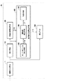
図1に示すように、本実施形態の画像処理装置Aは、動画像を構成する複数のフレーム画像を取得する画像入力手段1と、フレーム画像を縮小して縮小フレーム画像を得る縮小手段10と、縮小フレーム画像から仮補正値を求める仮補正値算出手段20と、仮補正値算出手段20により求められた仮補正値に基づいてフレーム画像の目的補正値を求める目的補正値算出手段40と、目的補正値算出手段40により求められた目的補正値を用いて各フレーム画像に対して補正を行って補正済み動画像を得る補正手段50とを有してなる。
As shown in FIG. 1, an image processing apparatus A according to this embodiment includes an
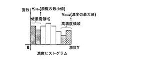
仮補正値算出手段20は、下記のように仮補正値を求める。まず、仮補正値算出手段20は、縮小手段10により取得された縮小フレーム画像に対して、図2に示す濃度ヒストグラムを作成する。このとき、縮小フレーム画像の画素数のα倍をmとし、濃度Yの高い方からm番目の濃度値をYmax、濃度Yの低い方からm番目の濃度値をYminとし、下記の式(1)によりヒストグラムの中間値Y0を求める。
The temporary correction value calculation means 20 calculates a temporary correction value as follows. First, the temporary correction
Y0=(Ymin+Ymax)/2 (1)
次に、仮補正値算出手段20は、算出した中間値Y0を用いて、式(2)に従って、縮小フレーム画像を露光補正するための補正値γ0を求める。
Y0 = (Ymin + Ymax) / 2 (1)
Next, the temporary correction
γ0=Yd−Y0 (2)
ここで、Ydは目標濃度であり、例えば標準光源の下における人物の肌領域の情報から推定することによって決定すればよい。または、例えば特開2000−101860や、特開2000−196890などの公報に記載された方法を用いて求めるようにしてもよい。
γ0 = Yd−Y0 (2)
Here, Yd is a target density, and may be determined by estimation from information on a human skin region under a standard light source, for example. Or you may make it obtain | require using the method described in gazettes, such as Unexamined-Japanese-Patent No. 2000-101860, Unexamined-Japanese-Patent No. 2000-196890, etc., for example.
仮補正値算出手段20は、各フレーム画像に対して求められたこの補正値γ0を夫々のフレーム画像の仮補正値として、目的補正値算出手段40に出力する。
The temporary correction
目的補正値算出手段40は、仮補正値算出手段20により算出した各々の仮補正値γ0が時間方向において平滑に変化するように各フレーム画像の仮補正値γ0を調整して、目的補正値γ1を得るものである。ここでは、例として、目的補正値算出手段40は、注目するフレーム画像の仮補正値γ0と、このフレーム画像およびその前後1つずつのフレーム画像の仮補正値γ0の平均値との重み付け加算によって仮補正値の調整を行うようにしているが、調整に用いられるフレーム画像は、注目するフレーム画像の前のみまたは後のみのフレーム画像を用いてもよいし、その数を増減してもよい。また、仮補正値の調整方法も、加算に限られるものではなく、仮補正値に対してローパスフィルタを適用したり、スプライン補間したりするなどの方法を用いてもよい。 The target correction value calculation means 40 adjusts the temporary correction value γ0 of each frame image so that each temporary correction value γ0 calculated by the temporary correction value calculation means 20 changes smoothly in the time direction, and the target correction value γ1. Is what you get. Here, as an example, the target correction value calculating means 40 performs weighted addition of the temporary correction value γ0 of the frame image of interest and the average value of the temporary correction value γ0 of the frame image and one frame image before and after the frame image. Although the temporary correction value is adjusted, the frame image used for the adjustment may be a frame image only before or after the frame image of interest, or the number thereof may be increased or decreased. Also, the adjustment method of the temporary correction value is not limited to the addition, and a method such as applying a low-pass filter to the temporary correction value or performing spline interpolation may be used.
図1に示すように、本実施形態における目的補正値算出手段40は、各々のフレーム画像に対して、該フレーム画像が場面の切替わりを示すカット点である確率の大きさであるカット点らしさβ0を算出するカット点らしさ算出手段25と、カット点らしさ算出手段25により算出したカット点らしさβ0に応じて、仮補正値γ0を調整する調整度β(その詳細については後述する)を算出する調整度算出手段30と、仮補正値γ0および調整度βを用いて、注目するフレーム画像と、注目するフレーム画像およびその前後の1つずつのフレーム画像の仮補正値γ0の平均値とを重み付け加算して注目するフレーム画像の目的補正値γ1を得る加算手段35とを有してなる。
As shown in FIG. 1, the target correction value calculation means 40 in the present embodiment is, for each frame image, the likelihood of a cut point that is the probability that the frame image is a cut point indicating a scene change. Cut point likelihood calculating means 25 for calculating β0, and an adjustment degree β (details will be described later) for adjusting the temporary correction value γ0 according to the cut point likelihood β0 calculated by the cut point
本実施形態におけるカット点らしさ算出手段25は、フレーム画像の濃度値のヒストグラムの形状に基づいて各フレーム画像のカット点らしさを算出するものである。具体的は、カット点らしさ算出手段25は、まず、縮小手段10により得られた各フレーム画像の縮小フレーム画像毎に、その濃度値のヒストグラムを求める。図3(a)は、カット点らしさ算出手段25により算出した各々のフレーム画像(ここでは縮小フレーム画像)のヒストグラムの例を示している(図中では、例として連続する6つのフレーム:f1、f2,f3,f4,f5,f6のヒストグラムを示している)。デジタル・ビデオカメラ、動画撮影可能なデジタルスチルカメラなどの撮像装置により被写体を撮像して動画像を得る際に、撮像装置の性能によりフレーム画像間に被写体と関係ない濃度段差が生じてしまうことがあるため、本実施形態のカット点らしさ算出手段25は、撮像装置の性能に起因するフレーム画像間の濃度段差を無くすために、各フレーム画像の代表値(ここでは、濃度値の平均値)をさらに算出すると共に、各フレーム画像の代表値が略等しくなるように、各フレーム画像のヒストグラムを濃度値軸において平行移動することにより、ヒストグラムの整合性を取る。この処理によって、図3(a)に示す例の各フレーム画像のヒストグラムが、撮像装置の性能に起因するフレーム画像間の濃度段差が解消され、図3(b)に示すようになる。なお、フレーム画像の代表値は、ここで用いられた濃度値の平均値以外に、メディアン、分散値(最大値,最小値)などを用いてもよい。
The cut point likelihood calculating means 25 in the present embodiment calculates the cut point likelihood of each frame image based on the shape of the histogram of density values of the frame image. Specifically, the cut point
次いで、カット点らしさ算出手段25は、図3(b)に示すような整合性の取れたヒストグラムを用いて、注目するフレーム画像の前後1つずつ(2つずつ以上であってもよい)のフレーム画像のヒストグラムの形状の平均を取って平均形状を得、注目するフレーム画像のヒストグラムの形状とこの平均形状との相関を求め、求められた相関が所定の第1の閾値以上である場合、注目するフレーム画像のカット点らしさを最小の0とし、相関が所定の第2の閾値(第2の閾値<第1の閾値)以下である場合、注目するフレーム画像のカット点らしさを最大の1とし、相関が第1の閾値と第2の閾値との間にある場合、相関が大きいほどカット点らしさが小さいように0と1との間で注目するフレーム画像のカット点らしさを求める。図3(c)は、図3(a)に示す例の6つのフレーム画像に対して求められたカット点らしさβ0を示している。
Next, the cut point likelihood calculation means 25 uses the histogram having consistency as shown in FIG. 3B, one by one before and after the target frame image (may be two or more). If the average shape of the histogram of the frame image is obtained to obtain an average shape, the correlation between the shape of the histogram of the frame image of interest and this average shape is obtained, and the obtained correlation is equal to or greater than a predetermined first threshold value, When the likelihood of the cut point of the frame image of interest is set to the
調整度算出手段30は、カット点らしさ算出手段25により算出されたカット点らしさβ0を用いて、下記の式(3)に従って仮補正値γ0を調整する調整度βを、各フレーム画像に対して算出する。 The adjustment degree calculation means 30 uses the cut point likelihood β0 calculated by the cut point likelihood calculation means 25 to adjust the adjustment degree β for adjusting the temporary correction value γ0 according to the following equation (3) for each frame image. calculate.
β(i)=1−β0(i) (3)
但し、β0:カット点らしさ
β:調整度
加算手段35は、調整度算出手段30により算出された調整度βと、仮補正値算出手段20により算出された仮補正値γ0を用いて、下記の式(4)に従って、注目するフレーム画像の目的補正値γ1を算出する。
β (i) = 1−β0 (i) (3)
However, β0: Like cut point
β: Degree of adjustment
The adding means 35 uses the adjustment degree β calculated by the adjustment degree calculation means 30 and the temporary correction value γ0 calculated by the temporary correction value calculation means 20, according to the following equation (4), A target correction value γ1 is calculated.
γ1(i)=(1−β(i))×γ0(i)
+β(i)×(γ0(i−1)+γ0(i)+γ0(i+1))/3 (4)
但し、γ1(i): 注目するフレーム画像の目的補正値
γ0(i): 注目するフレーム画像の仮補正値
γ0(i−1):注目するフレーム画像の前のフレーム画像の仮補正値
γ0(i+1):注目するフレーム画像の後のフレーム画像の仮補正値
β(i):注目するフレーム画像の調整度
目的補正値算出手段40は、加算手段35により得られた各々のフレーム画像の目的補正値γ1を補正手段50に出力する。
γ1 (i) = (1−β (i)) × γ0 (i)
+ Β (i) × (γ0 (i−1) + γ0 (i) + γ0 (i + 1)) / 3 (4)
Where γ1 (i): target correction value of the frame image of interest
γ0 (i): Temporary correction value of the frame image of interest
γ0 (i−1): provisional correction value of the frame image before the target frame image
γ0 (i + 1): provisional correction value of the frame image after the frame image of interest
β (i): Adjustment degree of the frame image of interest
The target correction
補正手段50は、目的補正値γ1を用いて下記の式(5)に従って、画像入力手段1により得られた各々のフレーム画像に対して補正を行って補正済み動画像を得る。 The correction means 50 corrects each frame image obtained by the image input means 1 according to the following equation (5) using the target correction value γ1 to obtain a corrected moving image.
YY=Y+γ1 (5)
但し、YY:補正後の濃度値
Y :補正前の濃度値
γ1 :目的補正値
ここで、本発明の主旨を分かりやすくするために、目的補正値算出手段40において、カット点らしさβ0を算出し、カット点らしさβ0に基づいて調整度βを算出し、調整度βを用いて仮補正値γ0の調整を行って目的補正値γ1を得るようにしているが、例えば調整度βを算出せずにカット点らしさβ0を用いて下記の式(6)に示すように直接目的補正値γ1を求めるようにしてもよい。
YY = Y + γ1 (5)
YY: density value after correction
Y: Density value before correction
γ1: target correction value
Here, in order to make the gist of the present invention easy to understand, the target correction value calculation means 40 calculates the cut point likelihood β0, calculates the adjustment degree β based on the cut point likelihood β0, and uses the adjustment degree β. The target correction value γ1 is obtained by adjusting the temporary correction value γ0. For example, the target correction value γ1 is directly calculated by using the cut point likelihood β0 without calculating the adjustment degree β as shown in the following formula (6). The value γ1 may be obtained.
γ1(i)=β0(i))×γ0(i)
+(1−β0(i))×(γ0(i−1)+γ0(i)+γ0(i+1))/3 (6)
但し、γ1(i): 注目するフレーム画像の目的補正値
γ0(i): 注目するフレーム画像の仮補正値
γ0(i−1):注目するフレーム画像の前のフレーム画像の仮補正値
γ0(i+1):注目するフレーム画像の後のフレーム画像の仮補正値
β0(i):注目するフレーム画像のカット点らしさ
図4は、図1に示す実施形態の画像処理装置Aにおいて行われる処理を示すフローチャートである。なお、図4のフローチャートは、動画像を構成する1つのフレーム画像に対して行われる処理を示すものであり、本実施形態の画像処理装置Aは、図4に示す処理を動画像を構成する各フレーム画像に対して行って補正済み動画を得る。
γ1 (i) = β0 (i)) × γ0 (i)
+ (1-β0 (i)) × (γ0 (i−1) + γ0 (i) + γ0 (i + 1)) / 3 (6)
However, γ1 (i): target correction value of the focused frame image γ0 (i): temporary correction value of the focused frame image γ0 (i−1): temporary correction value of the frame image before the focused frame image γ0 ( i + 1): Temporary correction value of the frame image after the frame image of interest β0 (i): Like cut point of the frame image of interest
FIG. 4 is a flowchart showing processing performed in the image processing apparatus A according to the embodiment shown in FIG. Note that the flowchart of FIG. 4 shows processing performed on one frame image constituting the moving image, and the image processing apparatus A of the present embodiment configures the processing shown in FIG. This is performed for each frame image to obtain a corrected moving image.
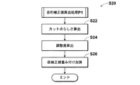
図4に示すように、画像入力手段1により得られたフレーム画像が、縮小手段10により縮小されて縮小フレーム画像となる(S10、S12)。仮補正値算出手段20は、縮小フレーム画像から、露光補正のための仮補正値γ0を算出する(S14)。目的補正値算出手段40は、各フレーム画像の仮補正値γ0が時間方向において平滑に変化するように、仮補正値γ0を調整して目的補正値γ1を算出する(S20)。補正手段50は、目的補正値γ1を用いて、画像入力手段1により得られたフレーム画像を補正する(S40)。なお、目的補正値算出手段40によりステップS20において行われる目的補正値算出処理P1の詳細は、図5のフローチャートに示されている。図示のように、目的補正値算出手段40において、まず、カット点らしさ算出手段25は注目するフレーム画像のカット点らしさβ0を算出し(S22)、次に調整度算出手段30は、カット点らしさβ0に基づいて注目するフレーム画像の調整度βを算出する(S24)。そして、加算手段35は、調整度βが小さいほど(カット点らしさβ0が大きいほど)、注目するフレーム画像の仮補正値の重みが大きい(すなわち、注目するフレーム画像の仮補正値の調整の程度が小さい)ように、注目するフレーム画像の仮補正値と、注目するフレーム画像およびその前後のフレーム画像の仮補正値の平均値とを重み付け加算して、注目するフレーム画像の目的補正値γ1を算出する(S26)。
As shown in FIG. 4, the frame image obtained by the image input means 1 is reduced by the reduction means 10 to become a reduced frame image (S10, S12). The temporary correction value calculation means 20 calculates a temporary correction value γ0 for exposure correction from the reduced frame image (S14). The target correction value calculation means 40 adjusts the temporary correction value γ0 and calculates the target correction value γ1 so that the temporary correction value γ0 of each frame image changes smoothly in the time direction (S20). The correcting
このように、本実施形態の画像処理装置Aによれば、動画像の各フレーム画像を補正して補正済み動画像を得るために、各フレーム画像の夫々から求められた仮補正値を、時間方向において平滑に変化するように調整して目的補正値を得る際に、各フレーム画像のカット点らしさに応じて、注目するフレーム画像のカット点らしさが大きいほど、このフレーム画像の仮補正値の重みを大きく、注目するフレーム画像とその前後のフレーム画像の仮補正値の平均値の重みを小さくする(すわわち、注目するフレーム画像の仮補正値を調整する程度を弱める)ようにして注目するフレーム画像と、注目するフレーム画像およびその前後のフレーム画像の仮補正値の平均値とを重み付け加算して注目するフレーム画像の目的補正値を得るようにしてため、カット点となるフレーム画像(カット点らしさが1となるフレーム画像)の目的補正値が、その前後のフレーム画像の仮補正値に影響されないようにすることができ、カット点のフレーム画像の適切な補正値を求めることができる。また、同じ場面における変化の小さい通常フレーム画像(カット点らしさが0のフレーム画像)の目的補正値が、その前後のフレーム画像の仮補正値に影響され、時間方向において平滑に変化するになるので、補正済み動画像に生じるちらつきを解消することができる。さらに、図13に示すような、同じ場面ではあるが、画像の変化が大きいフレーム画像(カット点らしさが、0より大きい1より小さいフレーム画像)の場合は、その目的補正値が、前後のフレーム画像の仮補正値に影響される一方、影響の程度は、通常フレーム画像のそれより小さい。そのため、補正済み動画像におけるちらつきを解消しつつ、同じ場面ではあるが、画像の変化が大きいフレーム画像でも、適切な補正が得られる。 As described above, according to the image processing apparatus A of the present embodiment, in order to obtain the corrected moving image by correcting each frame image of the moving image, the temporary correction value obtained from each of the frame images is used as the time. When the target correction value is obtained by adjusting so as to change smoothly in the direction, the provisional correction value of this frame image increases as the cut point likelihood of the frame image of interest increases according to the cut point likelihood of each frame image. Pay attention by increasing the weight and reducing the weight of the average value of the temporary correction values of the frame image of interest and the preceding and succeeding frame images (that is, reducing the degree of adjustment of the temporary correction value of the frame image of interest). The target frame image and the average value of the temporary correction values of the frame image of interest and the frame images before and after the frame image to obtain the target correction value of the frame image of interest. Therefore, the target correction value of the frame image serving as the cut point (the frame image having the cut point likelihood of 1) can be prevented from being affected by the temporary correction values of the preceding and succeeding frame images. An appropriate correction value can be obtained. In addition, since the target correction value of a normal frame image (a frame image with a cut point likelihood of 0) having a small change in the same scene is affected by the temporary correction values of the preceding and subsequent frame images, the target correction value changes smoothly in the time direction. Flickers that occur in the corrected moving image can be eliminated. Furthermore, in the same scene as shown in FIG. 13, in the case of a frame image with a large image change (a frame image whose cut point likelihood is less than 1 greater than 0), the target correction value is the previous and next frames. While being influenced by the temporary correction value of the image, the degree of the influence is smaller than that of the normal frame image. Therefore, while correcting flicker in the corrected moving image, appropriate correction can be obtained even in a frame image that is in the same scene but has a large image change.
図6は、本発明の第2の実施形態となる画像処理装置Bの構成を示すブロック図である。 FIG. 6 is a block diagram showing a configuration of an image processing apparatus B according to the second embodiment of the present invention.
図6に示すように、本実施形態の画像処理装置Bは、動画像を構成する複数のフレーム画像を取得する画像入力手段51と、フレーム画像を縮小して縮小フレーム画像を得る縮小手段55と、縮小フレーム画像の特徴量を算出する特徴量算出手段60と、特徴量算出手段60により算出された特徴量を用いて仮補正値を求める仮補正値算出手段65と、仮補正値算出手段65により求められた仮補正値を用いて縮小フレーム画像を補正して得られる仮補正済み縮小フレーム画像の特徴量を算出する仮補正手段70と、仮補正済み縮小フレーム画像の特徴量を用いて各縮小フレーム画像の目標特徴量を求める目標特徴量算出手段80と、特徴量算出手段60により算出された特徴量が、目標特徴量算出手段80により求められた目標特徴量になるように各フレーム画像の目的補正値を求める目的補正値算出手段90と、目的補正値算出手段90により求められた目的補正値を用いて各フレーム画像に対して補正を行って補正済み動画像を得る補正手段95とを有してなる。
As shown in FIG. 6, the image processing apparatus B of the present embodiment includes an
特徴量算出手段60と仮補正値算出手段65は、図1に示す画像処理装置Aの仮補正値算出手段20に相当し、画像処理装置Aの仮補正値算出手段20と同じように、縮小フレーム画像の特徴量Y0を求め、この特徴量Y0に基づいて縮小フレーム画像を露光補正するための補正値γ0を求めるものであり、ここで、その詳細な説明を省略する。なお、図8(a)下部の細線は、特徴量算出手段60により算出された特徴量Y0を示すものである。 The feature amount calculating means 60 and the temporary correction value calculating means 65 correspond to the temporary correction value calculating means 20 of the image processing apparatus A shown in FIG. 1, and are reduced in the same manner as the temporary correction value calculating means 20 of the image processing apparatus A. A feature value Y0 of the frame image is obtained, and a correction value γ0 for correcting the exposure of the reduced frame image based on the feature value Y0 is obtained, and detailed description thereof is omitted here. Note that the thin line at the bottom of FIG. 8A indicates the feature amount Y0 calculated by the feature amount calculation means 60.
仮補正値算出手段65は、補正値γ0を縮小フレーム画像の仮補正値として、仮補正手段70に出力する。
The temporary correction
仮補正手段70は、仮補正値算出手段65により得られた仮補正値γ0と、特徴量算出手段60により得られた特徴量Y0とを用いて、下記の式(7)に従って、仮補正値γ0を用いて縮小フレーム画像を補正して得られる仮補正済み縮小フレーム画像の特徴量Y1を求める。
The
Y1=Y0+γ0 (7)
但し、Y1:仮補正後の特徴量
Y0:仮補正前の特徴量
γ0 :仮補正値
ここで、処理の高速化を図るために、縮小フレーム画像に対して仮補正を行わずに直接仮補正済み縮小フレーム画像の特徴量Y1を求めるようにしているが、縮小フレーム画像に対して仮補正を行って仮補正済み縮小フレーム画像を得てから仮補正済み縮小フレーム画像の特徴量を求めるようにしてもよい。具体的には、下記の式(8)に従って、縮小フレーム画像に対して露光補正を行って、仮補正済み縮小フレーム画像を得る。
Y1 = Y0 + γ0 (7)
Y1: Feature value after temporary correction
Y0: feature value before temporary correction
γ0: Temporary correction value
Here, in order to increase the processing speed, the feature amount Y1 of the temporarily corrected reduced frame image is obtained directly without performing temporary correction on the reduced frame image. The feature amount of the temporarily corrected reduced frame image may be obtained after correction is performed to obtain the temporarily corrected reduced frame image. Specifically, exposure correction is performed on the reduced frame image according to the following equation (8) to obtain a temporarily corrected reduced frame image.
Y’=Y+γ0 (8)
但し、Y’:仮補正後の濃度値
Y :仮補正前の濃度値
γ0 :仮補正値
そして、仮補正済み縮小フレーム画像に対して、特徴量算出手段60と同じようにその濃度のヒストグラムの中間値を算出して仮補正済み縮小フレーム画像の特徴量Y1とすればよい。
Y ′ = Y + γ0 (8)
Y ′: Density value after provisional correction
Y: Density value before temporary correction
γ0: Temporary correction value
Then, for the temporarily corrected reduced frame image, an intermediate value of the histogram of the density may be calculated in the same manner as the feature amount calculating means 60 to obtain the feature amount Y1 of the temporarily corrected reduced frame image.
図8(a)中上部の細線は、仮補正手段70により求められた仮補正済み縮小フレーム画像の特徴量Y1を示している。図示のより、仮補正済み縮小フレーム画像の特徴量Y1は、時間方向における変動が大きく、このようなフレーム画像により構成される動画像を再生すると、ちらつきが生じてしまう。 The thin line at the top in FIG. 8A indicates the feature amount Y1 of the temporarily corrected reduced frame image obtained by the temporary correction means 70. As illustrated, the feature amount Y1 of the temporarily corrected reduced frame image varies greatly in the time direction, and flickering occurs when a moving image composed of such a frame image is reproduced.
目標特徴量算出手段80は、仮補正済み縮小フレーム画像の特徴量が時間方向において平滑に変化するように各仮補正済み縮小フレーム画像の特徴量を調整して目標特徴量を得るものであり、ここでは、例として、注目する仮補正済み縮小フレーム画像を中心とする5つの仮補正済み縮小フレーム画像の特徴量Y1に対してフィルリング処理(その詳細については後述する)を行うことにより注目する仮補正済み縮小フレーム画像の特徴量を調整して目標特徴量Y2を求める。図6に示すように、本実施形態における目標特徴量算出手段80は、各々のフレーム画像に対して、該フレーム画像が場面の切替わりを示すカット点である確率の大きさであるカット点らしさβ0を算出するカット点らしさ算出手段74と、カット点らしさ算出手段74により算出したカット点らしさβ0に応じて決められたフィルタで、注目する仮補正済み縮小フレーム画像を中心とする5つの仮補正済み縮小フレーム画像の特徴量Y1に対してフィルリング処理を行って注目する仮補正済み縮小フレーム画像の目標特徴量Y2を得るフィルタリング手段76とを有してなる。 The target feature amount calculation means 80 adjusts the feature amount of each temporarily corrected reduced frame image so as to obtain a target feature amount so that the feature amount of the temporarily corrected reduced frame image changes smoothly in the time direction. Here, as an example, attention is paid by performing a filling process (details will be described later) on the feature amount Y1 of the five temporarily corrected reduced frame images centered on the temporarily corrected reduced frame image of interest. The target feature amount Y2 is obtained by adjusting the feature amount of the temporarily corrected reduced frame image. As shown in FIG. 6, the target feature amount calculation means 80 in the present embodiment is, for each frame image, the likelihood of a cut point that is the magnitude of the probability that the frame image is a cut point indicating a scene change. Cut point likelihood calculation means 74 for calculating β0 and five temporary corrections centered on the temporarily corrected reduced frame image of interest with a filter determined according to the cut point likelihood β0 calculated by the cut point likelihood calculation means 74 And filtering means 76 for obtaining a target feature amount Y2 of the temporarily corrected reduced frame image to be noted by performing a filling process on the feature amount Y1 of the already reduced frame image.
目標特徴量算出手段80のカット点らしさ算出手段74は、図1に示す画像処理装置Aのカット点らしさ算出手段25と同じように、フレーム画像の濃度値のヒストグラムの形状に基づいてカット点らしさを算出するものであり、ここでその詳細な説明を省略する。なお、図8(a)に示す例の場合、時間t1に対応するフレーム画像が場面1と場面2との切替わりを示すカット点であって、そのカット点らしさが1となり、時間t2に対応するフレーム画像が場面2において画像が大きく変動するものであって、そのカット点らしさが1より小さい0より大きい値となる。
Like the cut point
フィルタリング手段76は、カット点らしさβ0と、カット点らしさに応じて用いられるフィルタFとが対応付けられた図示しないデータベースを有しており、図7は、このデータベースの1例を示している。なお、図中矢印は、カット点らしさが増大する方向を示している。 The filtering means 76 has a database (not shown) in which the cut point likelihood β0 is associated with the filter F used in accordance with the cut point likelihood, and FIG. 7 shows an example of this database. In addition, the arrow in the figure indicates the direction in which the likelihood of a cut point increases.
フィルタリング手段76は、図7に示すデータベースから、カット点らしさ算出手段74により算出されたカット点らしさβ0に対応したフィルタFを検出すると共に、検出されたフィルタFと、仮補正手段70により算出された仮補正済み縮小フレーム画像の特徴量Y1とを用いて下記の式(9)に従って、目標特徴量Y2を算出する。
The
Y2(i)=F×(Y1(i−2)+Y1(i−1)+Y1(i)
+Y1(i+1)+Y1(i+2))/5 (9)
但し,Y2(i):注目する仮補正済み縮小フレーム画像の目標特徴量
Y1(i):注目する仮補正済み縮小フレーム画像の特徴量
Y1(i−2):注目する仮補正済み縮小フレーム画像の2つ前の仮補正済み縮小フレーム画像の特徴量
Y1(i−1):注目する仮補正済み縮小フレーム画像の1つ前の仮補正済み縮小フレーム画像の特徴量
Y1(i+1):注目する仮補正済み縮小フレーム画像の1つ後の仮補正済み縮小フレーム画像の特徴量
Y1(i+2):注目する仮補正済み縮小フレーム画像の2つ後の仮補正済み縮小フレーム画像の特徴量
F:カット点らしさに対応したフィルタ
図7のフィルタおよび上記の式(9)から分かるように、注目する仮補正済み縮小フレーム画像のカット点らしさβ0が大きいほど、その目標特徴量Y2は、その前後の仮補正済み縮小フレーム画像の特徴量Y1による影響が小さく、カット点らしさが1となる仮補正済み縮小フレーム画像の場合、その目標特徴量Y2がまったく前後のフレーム画像に影響されない。また、注目する仮補正済み縮小フレーム画像のカット点らしさβ0が小さいほど、その目標特徴量Y2は、その前後の仮補正済み縮小フレーム画像の特徴量Y1による影響が大きく、カット点らしさが0となる仮補正済み縮小フレーム画像の場合、その目標特徴量Y2が前後4つの仮補正済み縮小フレーム画像の特徴量Y1との平均値となる。
Y2 (i) = F * (Y1 (i-2) + Y1 (i-1) + Y1 (i)
+ Y1 (i + 1) + Y1 (i + 2)) / 5 (9)
However, Y2 (i): target feature amount of the temporarily corrected reduced frame image to be noticed Y1 (i): feature amount of the temporarily corrected reduced frame image to be noticed Y1 (i-2): the temporarily corrected reduced frame image to be noticed Y1 (i-1): feature amount of the temporarily corrected reduced frame image immediately preceding the target temporarily corrected reduced frame image Y1 (i + 1): attention Feature amount of the temporarily corrected reduced frame image immediately after the temporarily corrected reduced frame image Y1 (i + 2): Feature amount of the temporarily corrected reduced frame image after the temporarily corrected reduced frame image of interest F: Cut Filter for pointiness
As can be seen from the filter of FIG. 7 and the above equation (9), as the cut point likelihood β0 of the temporarily corrected reduced frame image of interest increases, the target feature amount Y2 becomes larger than that of the temporarily corrected reduced frame images before and after that. In the case of a temporarily corrected reduced frame image in which the influence of the feature amount Y1 is small and the likelihood of a cut point is 1, the target feature amount Y2 is not affected by the preceding and following frame images. Further, as the cut point likelihood β0 of the temporarily corrected reduced frame image of interest is smaller, the target feature amount Y2 is more influenced by the feature amount Y1 of the temporarily corrected reduced frame images before and after that, and the cut point likelihood is 0. In the case of the temporarily corrected reduced frame image, the target feature amount Y2 is an average value of the feature amounts Y1 of the four temporarily corrected reduced frame images.
図8(a)中太線は、目標特徴量算出手段80により各縮小フレーム画像に対して求められた目標特徴量Y2を示している。 The thick line in FIG. 8A indicates the target feature amount Y2 obtained for each reduced frame image by the target feature amount calculation means 80.
目的補正値算出手段90は、特徴量算出手段60により求められた縮小フレーム画像の特徴量Y0が、目標特徴量算出手段80により求められた目標特徴量Y2になるように、下記の式(10)に従って補正値γ1を求め、この補正値γ1をフレーム画像の目的補正値として補正手段95に出力する。
The objective correction
γ1=Y2−Y0 (10)
但し,Y0:補正前の特徴量
Y2:目標特徴量
γ1:目的補正値
補正手段95は、目的補正値γ1を用いて下記の式(11)に従って、画像入力手段51により得られたフレーム画像に対して補正を行って補正済み動画像を得る。
γ1 = Y2−Y0 (10)
Y0: feature value before correction
Y2: target feature value
γ1: Target correction value
The correction means 95 corrects the frame image obtained by the image input means 51 according to the following equation (11) using the target correction value γ1 to obtain a corrected moving image.
YY=Y+γ1 (11)
但し、YY:補正後の濃度値
Y :補正前の濃度値
γ1 :目的補正値
図8(b)は、本実施形態の画像処理装置Bによる補正の結果を示すものであり、図中細線は、補正前の動画像を構成する各フレーム画像の特徴量を示しており、図中太線は、補正済み動画像を構成する各フレーム画像の特徴量を示している。図示のように、本実施形態の画像処理装置Bによれば、まず、補正済み動画像において、同じ場面における各フレーム画像の特徴量が平滑に変化するように補正されているため、補正済み動画像のちらつきを確実に解消している。さらに、カット点となるフレーム画像(時間t1に対応するフレーム画像)に対しては、その目標特徴量を求める際に、フィルタFとしては(0,0,5,0,0)が用いられ、前後の仮補正済み縮小フレーム画像の特徴量に影響されないため、目標特徴量に基づいて求められた補正値により適切な補正が施されている。また、時間t2に対応するフレーム画像のような、同じ場面ではあるが、画像の変化が大きいフレーム画像(カット点らしさが、0より大きい1より小さいフレーム画像)の場合は、その目標特徴量が、前後の仮補正済み縮小フレーム画像の特徴量に影響される一方、影響の程度は、通常フレーム画像のそれより小さいため、補正済み動画像におけるちらつきを解消しつつ、同じ場面ではあるが、画像の変化が大きいフレーム画像でも、適切な補正が得られる。
YY = Y + γ1 (11)
YY: density value after correction
Y: Density value before correction
γ1: target correction value
FIG. 8B shows the result of correction by the image processing apparatus B of the present embodiment, and the thin line in the figure shows the feature quantity of each frame image constituting the moving image before correction. The middle thick line indicates the feature amount of each frame image constituting the corrected moving image. As illustrated, according to the image processing apparatus B of the present embodiment, first, in the corrected moving image, the corrected moving image is corrected so that the feature amount of each frame image in the same scene changes smoothly. The flicker of the image is surely eliminated. Further, for a frame image that is a cut point (a frame image corresponding to the time t1), (0, 0, 5, 0, 0) is used as the filter F when obtaining the target feature amount. Since it is not affected by the feature values of the preceding and subsequent temporarily corrected reduced frame images, appropriate correction is performed using the correction value obtained based on the target feature value. Further, in the case of a frame image that is the same scene as the frame image corresponding to the time t2 but has a large image change (a frame image in which the likelihood of a cut point is less than 1 that is greater than 0), the target feature amount is While being affected by the feature amount of the temporarily corrected reduced frame images before and after, the degree of the influence is smaller than that of the normal frame image, so the flicker in the corrected moving image is eliminated and the image is the same scene. Appropriate correction can be obtained even in a frame image with a large change in.
また、画像処理装置Bは、動画像を構成する複数のフレーム画像に対して仮補正値を求め、この仮補正値による仮補正を行って得られる仮補正済みフレーム画像の特徴量が時間方向において平滑に変化するようにして各仮補正済みフレームの特徴量を調整して得た値を目標特徴量とし、フレーム画像の特徴量がこの目標特徴量と略等しくなるように各フレーム画像の目的補正値を求めるようにしているので、目的補正値が、仮補正による画質向上の効果を生かしつつ、目標特徴量、すなわち補正後のフレーム画像の特徴量の推移を直接抑制するようにして得たものであるので、仮補正値の推移のみを抑制する図1に示す画像処理装置Aよりもより確実に補正済み動画像のちらつきを解消することができる。 Further, the image processing apparatus B obtains a temporary correction value for a plurality of frame images constituting the moving image, and the feature amount of the temporarily corrected frame image obtained by performing the temporary correction using the temporary correction value is in the time direction. The value obtained by adjusting the feature value of each temporarily corrected frame so as to change smoothly is used as the target feature value, and the target correction of each frame image is performed so that the feature value of the frame image becomes substantially equal to the target feature value. The target correction value is obtained by directly suppressing the transition of the target feature amount, that is, the feature amount of the corrected frame image, while taking advantage of the image quality improvement effect of the temporary correction. Therefore, the flicker of the corrected moving image can be resolved more reliably than the image processing apparatus A shown in FIG. 1 that suppresses only the transition of the temporary correction value.
次いで図9のフローチャートを参照して本実施形態の画像処理装置Bにおいて行われる処理を説明する。なお、図9のフローチャートは、動画像を構成する1つのフレーム画像に対して行われる処理を示すものであり、本実施形態の画像処理装置Bは、図9に示す処理を動画像を構成する各フレーム画像に対して行って補正済み動画を得る。 Next, processing performed in the image processing apparatus B of the present embodiment will be described with reference to the flowchart of FIG. Note that the flowchart in FIG. 9 shows processing performed on one frame image constituting the moving image, and the image processing apparatus B of the present embodiment configures the processing shown in FIG. 9 in the moving image. This is performed for each frame image to obtain a corrected moving image.
図9に示すように、画像入力手段51により得られたフレーム画像が、縮小手段55により縮小されて縮小フレーム画像となる(S51、S52)。特徴量算出手段60は、この縮小フレーム画像から特徴量Y0を算出する(S54)。仮補正値算出手段65は、特徴量Y0に基づいて、露光補正のための仮補正値γ0を算出し(S56)、仮補正手段70は、仮補正値γ0およびステップS54において算出された特徴量Y0を用いて仮補正済み縮小フレーム画像の特徴量Y1を算出する(S58)。目標特徴量算出手段80は、特徴量Y1が時間方向において平滑に変化するように、特徴量Y1を調整して目標特徴量Y2を得る(S60)。目的補正値算出手段90は、ステップS54において算出された特徴量Y0が、ステップS60において算出された目標特徴量Y2になるように目的補正値γ1を算出する(S70)。補正手段95は、目的補正値γ1を用いて、画像入力手段51により得られたフレーム画像を補正する(S72)。なお、目標特徴量算出手段80によりステップS60において行われる目標特徴量算出処理P2の詳細は、図10のフローチャートに示されている。図示のように、目標特徴量算出手段80において、まず、カット点らしさ算出手段74は注目するフレーム画像のカット点らしさβ0を算出する(S62)。次にフィルタリング手段76は、カット点らしさβ0に対応したフィルタを選択すると共に、注目するフレーム画像を中心とする5つの連続するフレーム画像の特徴量Y1(仮補正済み縮小フレーム画像の特徴量)に対して、選択されたフィルタを適用することによって、注目するフレーム画像の目標特徴量Y2を算出する(S64、S66)。なお、ステップS64において選出されたフィルタは、図7に示すように、カット点らしさβ0が大きいフレーム画像ほど、その目標特徴量が前後のフレーム画像に影響される程度が小さくなるようにするものである。
As shown in FIG. 9, the frame image obtained by the image input means 51 is reduced by the reduction means 55 to become a reduced frame image (S51, S52). The feature amount calculating means 60 calculates a feature amount Y0 from the reduced frame image (S54). The temporary correction
図11は、本発明の第3の実施形態となる画像処理装置Cの構成を示すブロック図である。図示のように、本実施形態の画像処理装置Cは、動画像を構成する複数のフレーム画像を取得する画像入力手段101と、フレーム画像を縮小して縮小フレーム画像を得る縮小手段110と、縮小フレーム画像の特徴量を算出する特徴量算出手段115と、特徴量算出手段115により算出された特徴量を用いて仮補正値を求める仮補正値算出手段120と、仮補正値算出手段120により求められた仮補正値を用いて縮小フレーム画像を補正して得られる仮補正済み縮小フレーム画像の特徴量を算出する仮補正手段130と、仮補正済み縮小フレーム画像の特徴量を用いて各縮小フレーム画像の目標特徴量を求める目標特徴量算出手段140と、特徴量算出手段115により算出された特徴量が、目標特徴量算出手段140により求められた目標特徴量になるように各フレーム画像の目的補正値を求める目的補正値算出手段150と、目的補正値算出手段150により求められた目的補正値を用いて各フレーム画像に対して補正を行って補正済み動画像を得る補正手段160とを有してなる。なお、本実施形態の画像処理装置Cは、図5に示す実施形態の画像処理装置Bとは、目標特徴量算出手段140と目標特徴量算出手段80とが異なる点以外、その他の全ての構成が同様であるので、ここで、目標特徴量算出手段140において行われる処理のみについて説明し、他の構成の詳細な説明を省略する。
FIG. 11 is a block diagram showing a configuration of an image processing apparatus C according to the third embodiment of the present invention. As illustrated, the image processing apparatus C according to the present embodiment includes an
画像処理装置Cの目標特徴量算出手段140は、仮補正済み縮小フレーム画像の特徴量が時間方向において平滑に変化するように各仮補正済み縮小フレーム画像の特徴量を調整して目標特徴量を得るものであり、図11に示すように、各々のフレーム画像に対して、該フレーム画像が場面の切替わりを示すカット点である確率の大きさであるカット点らしさβ0を算出するカット点らしさ算出手段142と、仮補正手段130により得られた各々の仮補正済み縮小フレーム画像の特徴量Y1を平滑化して仮目標特徴量Y1aを得る仮目標特徴量算出手段144と、注目する仮補正済み縮小フレーム画像のカット点らしさβ0に応じた重みで、注目する仮補正済み縮小フレーム画像の特徴量Y1と仮目標特徴量Y1aとを重み付け加算して目標特徴量Y2を得る加算手段146とを有してなる。
The target feature
カット点らしさ算出手段142は、図5に示す画像処理装置Bのカット点らしさ算出手段74と同じように、フレーム画像の濃度値のヒストグラムの形状に基づいてカット点らしさを算出するものであり、ここでその詳細な説明を省略する。
Like the cut point
仮目標特徴量算出手段144は、注目する仮補正済み縮小フレーム画像を中心とする5つ(注目する仮補正済み縮小フレーム画像の2つ前の仮補正済み縮小フレーム画像から、注目する仮補正済み縮小フレーム画像の2つ後の仮補正済み縮小フレーム画像までの5つ)の仮補正済み縮小フレーム画像の特徴量Y1に対して平均を取って得た値を、注目する仮補正済み縮小フレーム画像の仮目標特徴量Y1aとする。
The temporary target feature
加算手段146は、下記の式(12)に従って、注目する仮補正済み縮小フレーム画像のカット点らしさβ0が大きいほど、その特徴量Y1の重みが大きく、仮目標特徴量Y1aの重みが小さくなるように、特徴量Y1と仮目標特徴量Y1aとを重み付け加算することによって、注目する仮補正済み縮小フレーム画像の目標特徴量Y2を得る。
According to the following equation (12), the adding
Y2=β0×Y1+(1−β0)×Y1a (12)
但し、Y2:注目する仮補正済み縮小フレーム画像の目標特徴量
Y1:注目する仮補正済み縮小フレーム画像の特徴量
Y1a:仮目標特徴量
β0:注目する仮補正済み縮小フレーム画像のカット点らしさ
図12は、図11に示す画像処理装置Cにおける目標特徴量算出手段140に置いて行われる処理を示すフローチャートである。図示のように、画像処理装置Cの目標特徴量算出手段140は、カット点らしさ算出手段142により注目するフレーム画像のカット点らしさβ0が算出される(S100)と共に、仮目標特徴量算出手段144により、注目する仮補正済みフレーム画像の2つ前の仮補正済み縮小フレーム画像から、注目する仮補正済みフレーム画像の2つ後の仮補正済み縮小フレーム画像までの5つの仮補正済み縮小フレーム画像の特徴量Y1の平均を取ることによって注目する仮補正済み縮小フレーム画像の仮目標特徴量Y1aが求められる(S110)。そして、加算手段146により注目する仮補正済み縮小フレーム画像の特徴量Y1とその仮目標特徴量Y1aとを重み付け加算することによって目標特徴量Y2が求められる(S120)。なお、加算手段146によるステップS120の重み付け加算は、カット点らしさβ0が大きいほど、特徴量Y1の重みが大きく、仮目標特徴量Y1aの重みが小さいようにして行われたものである。
Y2 = β0 × Y1 + (1−β0) × Y1a (12)
Y2: target feature amount of the temporarily corrected reduced frame image of interest Y1: feature amount of the temporarily corrected reduced frame image of interest Y1a: temporary target feature amount β0: likelihood of a cut point of the temporarily corrected reduced frame image of interest
FIG. 12 is a flowchart showing processing performed in the target feature
本実施形態の画像処理装置Cは、画像処理装置Bとは目標特徴量の算出方法が異なるものの、カット点らしさが大きいフレーム画像ほど、その目標特徴量は前後のフレーム画像に影響される程度が小さいように求められるので、画像処理装置Bと同じ効果を得ることができる。さらに、カット点らしさに応じて、特徴量Y1と仮目標特徴量Y1aの重みを調整するようにしているので、処理が簡単である。 Although the image processing device C of the present embodiment is different from the image processing device B in the calculation method of the target feature amount, the target feature amount is affected by the preceding and succeeding frame images as the frame image is more likely to be cut. Since it is required to be small, the same effect as the image processing apparatus B can be obtained. Furthermore, since the weights of the feature amount Y1 and the temporary target feature amount Y1a are adjusted according to the cut point likelihood, the processing is simple.
以上、本発明の望ましい実施形態について説明したが、本発明の画像処理方法および装置並びにそのためのプログラムは、上述した実施形態に限られることがなく、本発明の主旨を逸脱しない限り、上述した各実施形態の構成を組み合わせたり、増減、変化を加えたりすることができる。 The preferred embodiments of the present invention have been described above. However, the image processing method and apparatus of the present invention and the program therefor are not limited to the above-described embodiments, and each of the above-described embodiments is not departed from the gist of the present invention. The configuration of the embodiment can be combined, increased, decreased, or changed.
例えば、画像処理装置Bと画像処理装置Cにおいて、仮補正値の算出から目標特徴量の算出までの処理を、動画像を構成する各フレーム画像に対して行うようになっているが、例えば、動画像を構成するフレーム画像から参照フレーム画像を選出し、選出された参照フレーム画像に対してのみ目標特徴量を算出するまでの処理を行うと共に、参照フレーム画像の目標特徴量に対してスプライン補間や、線形補間などの補間処理を行うことによって他のフレーム画像の目標特徴量を求めるようにしてもよい。こうすることによって、仮補正値の算出、仮補正済み縮小フレーム画像の特徴量の算出などの処理は、参照フレーム画像に対してのみ行われる、処理の高速化を図ることができる。なお、参照フレーム画像の選出は、例えば、時間方向におけるフレーム画像間の類似度を求め、参照フレーム画像の間隔を決定するようにして行われることができる。ここで類似度としては例えば相関が大きいほど類似度が高いように、フレーム画像間の相関を用いることができる。また、決められた参照フレーム画像の間隔がn(n:2以上の整数)であるとすれば、動画像を構成する各フレーム画像(フレーム画像1、フレーム画像2、...)のうちのフレーム画像1、フレーム画像(n+1)、フレーム画像(2n+1)、フレーム画像(3n+1)...のフレーム画像が参照フレーム画像とするようにすればよい。
For example, in the image processing apparatus B and the image processing apparatus C, the processing from the calculation of the temporary correction value to the calculation of the target feature amount is performed on each frame image constituting the moving image. A reference frame image is selected from the frame images constituting the moving image, processing is performed until the target feature amount is calculated only for the selected reference frame image, and spline interpolation is performed on the target feature amount of the reference frame image. Alternatively, the target feature amount of another frame image may be obtained by performing interpolation processing such as linear interpolation. By doing so, processing such as calculation of the temporary correction value and calculation of the feature amount of the temporarily corrected reduced frame image is performed only on the reference frame image, and the processing speed can be increased. The selection of the reference frame image can be performed, for example, by obtaining the similarity between the frame images in the time direction and determining the interval between the reference frame images. Here, as the similarity, for example, the correlation between the frame images can be used so that the higher the correlation is, the higher the similarity is. Also, if the determined interval between reference frame images is n (n: an integer equal to or greater than 2), each of the frame images (
また、上述した実施形態の画像処理装置は、縮小フレーム画像に対して特徴量の算出から目的補正値までの処理を行うようにして処理の高速化を図っているが、フレーム画像を縮小せずにこれらの処理を行うようにしてもよい。また、縮小フレーム画像を縮小して処理する場合において、要求される処理時間や、元のフレーム画像の解像度に応じて縮小率を調整することができるようにしてもよい。 In the image processing apparatus according to the above-described embodiment, the processing from the calculation of the feature amount to the target correction value is performed on the reduced frame image so as to increase the processing speed. However, the frame image is not reduced. Alternatively, these processes may be performed. In the case where the reduced frame image is reduced and processed, the reduction ratio may be adjusted according to the required processing time and the resolution of the original frame image.
また、上述した実施形態の画像処理装置は、フレーム画像の特徴量として濃度のヒストグラムの中間値Y0を用いたが、フレーム画像内の濃度の平均値、メディアンなどの代表値などを特徴量として用いるようにしてもよい。 In the image processing apparatus according to the above-described embodiment, the intermediate value Y0 of the density histogram is used as the feature amount of the frame image. However, the average value of the density in the frame image, a representative value such as a median, and the like are used as the feature amount. You may do it.
また、上述した実施形態に用いられる濃度の代わりに、輝度などを用いてもよい。 Further, brightness or the like may be used instead of the density used in the above-described embodiment.
また、上述した画像処理装置は、例として動画像に対して露光補正を行うものであるが、本発明の画像処理方法および装置は、露光補正に限らず、前述したホワイトバランス補正、彩度補正、コントラスト補正、シャープネス補正、色補正などの他の画質補正およびこれらの画質補正の組合せにも適用することができる。 The image processing apparatus described above performs exposure correction on a moving image as an example. However, the image processing method and apparatus of the present invention are not limited to exposure correction, but include the above-described white balance correction and saturation correction. The present invention can also be applied to other image quality corrections such as contrast correction, sharpness correction, and color correction, and combinations of these image quality corrections.
また、上述した画像処理装置は、フレーム画像に対して求めた目的補正値を用いて補正を行うまでの処理を行っているが、補正を実行せずに、元の動画像に目的補正値を付属させて記録媒体に記録したり、ネットワーク上の処理装置に送信したりなどをして、指示がされたときに補正を実行するようにしてもよい。 In addition, the image processing apparatus described above performs processing until correction is performed using the target correction value obtained for the frame image, but the target correction value is applied to the original moving image without performing the correction. Correction may be executed when an instruction is given by attaching it to a recording medium or transmitting it to a processing device on a network.
1 画像入力手段
10 縮小手段
20 仮補正値算出手段
25 カット点らしさ算出手段
30 調整度算出手段
35 加算手段
40 目的補正値算出手段
50 補正手段
51 画像入力手段
55 縮小手段
60 特徴量算出手段
65 仮補正値算出手段
70 仮補正手段
74 カット点らしさ算出手段
76 フィルタリング手段
80 目標特徴量算出手段
90 目的補正値算出手段
95 補正手段
101 画像入力手段
110 縮小手段
115 特徴量算出手段
120 仮補正値算出手段
130 仮補正手段
140 目標特徴量算出手段
142 カット点らしさ算出手段
144 仮目標特徴量算出手段
146 加算手段
150 目的補正値算出手段
160 補正手段
β0 カット点らしさ
γ0 仮補正値
γ1 目的補正値
DESCRIPTION OF
Claims (12)
前記フレーム画像の画質を補正するための仮補正値を求め、
該仮補正値を用いて前記各フレーム画像を補正し、
補正後の各仮補正済みフレーム画像の特徴量を算出し、
前記カット点らしさが大きい前記フレーム画像ほど前記特徴量の変化を平滑化させる平滑程度が弱くなるように、前記各仮補正済みフレーム画像の前記特徴量に対し時間方向において平滑化処理を施すことにより、前記各仮補正済みフレーム画像の特徴量を調節したものを目標特徴量として求め、
前記フレーム画像の特徴量が該フレーム画像の前記目標特徴量と略等しくなるように前記各フレーム画像を補正する
ことを特徴とする画像処理方法。 Calculating a feature amount of each frame image constituting a moving image, a likeness cut point indicating the magnitude of the probability is a cut point of the frame image showing the switching comparatively scene in the moving image,
Obtaining a temporary correction value for correcting the image quality of the frame image;
Correct each frame image using the temporary correction value ,
Calculate the feature value of each temporarily corrected frame image after correction,
By performing a smoothing process in the time direction on the feature amount of each provisionally corrected frame image so that the frame image having a higher likelihood of the cut point has a lower smoothness level that smoothes the change in the feature amount. obtains a material obtained by adjusting the characteristics of each temporarily corrected frame image as the target feature amount,
Each frame image is corrected so that the feature amount of the frame image is substantially equal to the target feature amount of the frame image.
An image processing method.
前記各フレーム画像から該フレーム画像の画質を補正するための仮補正値を求め、
該仮補正値を用いて前記各フレーム画像を補正し、
補正後の各仮補正済みフレーム画像の特徴量を算出し、
前記カット点らしさが大きい前記フレーム画像ほど前記特徴量の変化を平滑化させる平滑程度が弱くなるように、算出した前記各仮補正済みフレーム画像の特徴量に対し時間方向において平滑化処理を施すことにより、前記各仮補正済みフレーム画像の特徴量を調整したものを仮目標特徴量として求め、
前記仮補正済みフレーム画像の特徴量と該フレーム画像の前記仮目標特徴量とを重み付け加算して得た値を前記フレーム画像の目標特徴量として求め、
前記フレーム画像の特徴量が該フレーム画像の前記目標特徴量と略等しくなるように前記各フレーム画像を補正する
ことを特徴とする画像処理方法。 The feature amount of each frame image constituting the moving image and the cut point likelihood indicating the probability that the frame image is a cut point indicating scene switching in the moving image are calculated for each frame image. And
A temporary correction value for correcting the image quality of the frame image is obtained from each frame image,
Correct each frame image using the temporary correction value ,
Calculate the feature value of each temporarily corrected frame image after correction,
Applying a smoothing process in the time direction to the calculated feature amount of each provisionally corrected frame image so that the smoothness level for smoothing the change in the feature amount becomes weaker as the frame image has a higher likelihood of the cut point. To obtain a temporary target feature value obtained by adjusting the feature value of each provisionally corrected frame image,
Obtaining a value obtained by weighted addition of the feature amount of the provisionally corrected frame image and the provisional target feature amount of the frame image as the target feature amount of the frame image ;
An image processing method , wherein each frame image is corrected so that a feature amount of the frame image is substantially equal to the target feature amount of the frame image .
前記参照フレーム画像の前記目標特徴量に対して補間処理を行うことによって前記動画像を構成する前記各フレーム画像の前記目標特徴量を得ることを特徴とする請求項1または2記載の画像処理方法。 The target feature amount is calculated only for the reference frame image selected from each frame image constituting the moving image,
The image processing method according to claim 1 or 2, wherein the obtaining the target characteristic quantity of each frame image constituting the moving image by performing an interpolation process with respect to the target characteristic quantity of the reference frame picture .
前記フレーム画像が前記動画像における場面の切替わりを示すカット点である確率の大きさを示すカット点らしさを前記各フレーム画像に対して求めるカット点らしさ算出手段と、
前記各フレーム画像の特徴量の目標値である目標特徴量を求める目標特徴量算出手段と、
前記フレーム画像の特徴量が該フレーム画像の前記目標特徴量と略等しくなるように前目的補正値を求める目的補正値算出手段と、
前記目的補正値を用いて前記フレーム画像を補正する補正手段と
を有し、
前記目標特徴量算出手段が、
前記各フレーム画像から該フレーム画像の画質を補正するための仮補正値を求める仮補正値算出手段と、
該仮補正値を用いて前記各フレーム画像を補正して得られる仮補正済みフレーム画像の特徴量を算出する仮補正手段と、
前記カット点らしさが大きい前記フレーム画像ほど前記特徴量の変化を平滑化させる平滑程度が弱くなるように、算出した前記各仮補正済みフレーム画像の特徴量に対し時間方向において平滑化処理を施すことにより、前記各仮補正済みフレーム画像の特徴量を調節したものを目標特徴量として求める特徴量平滑化手段と
を備えたことを特徴とする画像処理装置。 A feature amount calculating means for calculating a feature amount of each frame image of a plurality of frame images constituting the moving image;
A likeness cut point calculation means for obtaining relative to the frame image is the probability a cut point showing the switching comparatively scene in the video size each frame image likeness cut point indicating a
Target feature amount calculating means for obtaining a target feature amount that is a target value of the feature amount of each frame image;
Objective correction value calculation means for obtaining a previous objective correction value such that the feature quantity of the frame image is substantially equal to the target feature quantity of the frame image;
Correction means for correcting the frame image using the target correction value;
Have
The target feature amount calculating means includes
Provisional correction value calculation means for obtaining a provisional correction value for correcting the image quality of the frame image from each frame image;
Temporary correction means for calculating a feature amount of a temporarily corrected frame image obtained by correcting each frame image using the temporary correction value;
Applying a smoothing process in the time direction to the calculated feature amount of each provisionally corrected frame image so that the smoothness level for smoothing the change in the feature amount becomes weaker as the frame image has a higher likelihood of the cut point. Accordingly, the each temporarily corrected frame image feature amount smoothing means Ru calculated as the target feature amount obtained by adjusting the characteristics of
The image processing apparatus characterized by comprising a.
前記フレーム画像が前記動画像における場面の切替わりを示すカット点である確率の大きさを示すカット点らしさを前記各フレーム画像に対して求めるカット点らしさ算出手段と、
前記フレーム画像の特徴量の目標値である目標特徴量を求める目標特徴量算出手段と、
前記フレーム画像の特徴量が該フレーム画像の前記目標特徴量と略等しくなるように前目的補正値を求める目的補正値算出手段と、
前記目的補正値を用いて前記フレーム画像を補正する補正手段と
を有し、
前記目標特徴量算出手段が、
前記各フレーム画像から該フレーム画像の画質を補正するための仮補正値を求める仮補正値算出手段と、
該仮補正値を用いて前記各フレーム画像を補正して得られる仮補正済みフレーム画像の特徴量を算出する仮補正手段と、
前記カット点らしさが大きい前記フレーム画像ほど前記特徴量の変化を平滑化させる平滑程度が弱くなるように、算出した前記各仮補正済みフレーム画像の特徴量に対し時間方向において平滑化処理を施すことにより、前記各仮補正済みフレーム画像の特徴量を調整したものを仮目標特徴量として求める特徴量平滑化手段と、
前記仮補正済みフレーム画像の特徴量と該フレーム画像の前記仮目標特徴量とを重み付け加算して得た値を前記フレーム画像の目標特徴量として求める重付加算手段と
を備えたことを特徴とする画像処理装置。 A feature amount calculating means for calculating a feature amount of each frame image of a plurality of frame images constituting the moving image;
A likeness cut point calculation means for obtaining relative to the frame image is the probability a cut point showing the switching comparatively scene in the video size each frame image likeness cut point indicating a
Target feature amount calculating means for obtaining a target feature amount that is a target value of the feature amount of the frame image;
Objective correction value calculation means for obtaining a previous objective correction value such that the feature quantity of the frame image is substantially equal to the target feature quantity of the frame image;
Correction means for correcting the frame image using the target correction value;
Have
The target feature amount calculating means includes
Provisional correction value calculation means for obtaining a provisional correction value for correcting the image quality of the frame image from each frame image;
Temporary correction means for calculating a feature amount of a temporarily corrected frame image obtained by correcting each frame image using the temporary correction value;
Applying a smoothing process in the time direction to the calculated feature amount of each provisionally corrected frame image so that the smoothness level for smoothing the change in the feature amount becomes weaker as the frame image has a higher likelihood of the cut point. The feature amount smoothing means for obtaining the provisional target feature amount by adjusting the feature amount of each provisionally corrected frame image,
Weighted addition means for obtaining a value obtained by weighted addition of the feature amount of the provisionally corrected frame image and the provisional target feature amount of the frame image as the target feature amount of the frame image;
An image processing apparatus comprising:
動画像を構成する各フレーム画像の特徴量と、該フレーム画像が前記動画像における場面の切替わりを示すカット点である確率の大きさを示すカット点らしさとを算出し、 Calculating the feature amount of each frame image constituting the moving image and the cut point likelihood indicating the probability that the frame image is a cut point indicating scene switching in the moving image;
前記フレーム画像の画質を補正するための仮補正値を求め、 Obtaining a temporary correction value for correcting the image quality of the frame image;
該仮補正値を用いて前記各フレーム画像を補正し、 Correct each frame image using the temporary correction value,
補正後の各仮補正済みフレーム画像の特徴量を算出し、 Calculate the feature value of each temporarily corrected frame image after correction,
前記カット点らしさが大きい前記フレーム画像ほど前記特徴量の変化を平滑化させる平滑程度が弱くなるように、算出した前記各仮補正済みフレーム画像の特徴量に対し時間方向において平滑化処理を施すことにより、前記各仮補正済みフレーム画像の特徴量を調節したものを目標特徴量として求め、Applying a smoothing process in the time direction to the calculated feature amount of each provisionally corrected frame image so that the smoothness level for smoothing the change in the feature amount becomes weaker as the frame image has a higher likelihood of the cut point. To obtain a target feature value obtained by adjusting the feature value of each provisionally corrected frame image,
前記フレーム画像の特徴量が該フレーム画像の前記目標特徴量と略等しくなるように前記各フレーム画像を補正する Each frame image is corrected so that the feature amount of the frame image is substantially equal to the target feature amount of the frame image.
ことを実行させるためのプログラム。 A program to make things happen.
動画像を構成する各フレーム画像の特徴量と、該フレーム画像が前記動画像における場面の切替わりを示すカット点である確率の大きさを示すカット点らしさとを前記各フレーム画像に対して算出し、 The feature amount of each frame image constituting the moving image and the cut point likelihood indicating the probability that the frame image is a cut point indicating scene switching in the moving image are calculated for each frame image. And
前記各フレーム画像から該フレーム画像の画質を補正するための仮補正値を求め、 A temporary correction value for correcting the image quality of the frame image is obtained from each frame image,
該仮補正値を用いて前記各フレーム画像を補正し、 Correct each frame image using the temporary correction value,
補正後の各仮補正済みフレーム画像の特徴量を算出し、 Calculate the feature value of each temporarily corrected frame image after correction,
算出した前記各仮補正済みフレーム画像の特徴量が時間方向において平滑に変化するように、前記カット点らしさが大きい前記フレーム画像ほど前記特徴量の変化を平滑化させる平滑程度が弱くなるように、前記各仮補正済みフレーム画像の特徴量を調整したものを前記フレーム画像の仮目標特徴量として求め、 In order that the calculated feature amount of each of the temporarily corrected frame images changes smoothly in the time direction, the smoothness degree that smoothes the change in the feature amount is weakened as the frame image having a higher likelihood of the cut point is obtained. Obtained as a temporary target feature amount of the frame image the adjustment of the feature amount of each temporarily corrected frame image,
前記仮補正済みフレーム画像の特徴量と該フレーム画像の前記仮目標特徴量とを重み付け加算して得た値を前記フレーム画像の目標特徴量として求め、 Obtaining a value obtained by weighted addition of the feature amount of the provisionally corrected frame image and the provisional target feature amount of the frame image as the target feature amount of the frame image;
前記フレーム画像の特徴量が該フレーム画像の前記目標特徴量と略等しくなるように前記各フレーム画像を補正する Each frame image is corrected so that the feature amount of the frame image is substantially equal to the target feature amount of the frame image.
ことを実行させるためのプログラム。 A program to make things happen.
前記参照フレーム画像の前記目標特徴量に対して補間処理を行うことによって前記動画像を構成する前記各フレーム画像の前記目標特徴量を得ることを特徴とする請求項9または10記載のプログラム The program according to claim 9 or 10, wherein the target feature amount of each frame image constituting the moving image is obtained by performing an interpolation process on the target feature amount of the reference frame image.
Priority Applications (2)
| Application Number | Priority Date | Filing Date | Title |
|---|---|---|---|
| JP2004082804A JP4265986B2 (en) | 2004-03-22 | 2004-03-22 | Image processing method, apparatus, and program |
| US11/082,783 US7680326B2 (en) | 2004-03-18 | 2005-03-18 | Method, system, and program for correcting the image quality of a moving image |
Applications Claiming Priority (1)
| Application Number | Priority Date | Filing Date | Title |
|---|---|---|---|
| JP2004082804A JP4265986B2 (en) | 2004-03-22 | 2004-03-22 | Image processing method, apparatus, and program |
Publications (3)
| Publication Number | Publication Date |
|---|---|
| JP2005269542A JP2005269542A (en) | 2005-09-29 |
| JP2005269542A5 JP2005269542A5 (en) | 2006-07-06 |
| JP4265986B2 true JP4265986B2 (en) | 2009-05-20 |
Family
ID=35093556
Family Applications (1)
| Application Number | Title | Priority Date | Filing Date |
|---|---|---|---|
| JP2004082804A Expired - Fee Related JP4265986B2 (en) | 2004-03-18 | 2004-03-22 | Image processing method, apparatus, and program |
Country Status (1)
| Country | Link |
|---|---|
| JP (1) | JP4265986B2 (en) |
Families Citing this family (5)
| Publication number | Priority date | Publication date | Assignee | Title |
|---|---|---|---|---|
| JP4850689B2 (en) * | 2006-12-22 | 2012-01-11 | キヤノン株式会社 | Image processing apparatus, image processing method, image processing program, and storage medium |
| JP5050637B2 (en) * | 2007-05-11 | 2012-10-17 | ソニー株式会社 | VIDEO SIGNAL PROCESSING DEVICE, VIDEO SIGNAL PROCESSING METHOD, VIDEO SIGNAL PROCESSING METHOD PROGRAM, AND RECORDING MEDIUM CONTAINING VIDEO SIGNAL PROCESSING METHOD PROGRAM |
| JP5299282B2 (en) * | 2007-11-13 | 2013-09-25 | 富士通株式会社 | Image correction device |
| JP5226590B2 (en) | 2009-04-02 | 2013-07-03 | キヤノン株式会社 | Image analysis apparatus, image processing apparatus, and image analysis method |
| JP5509014B2 (en) * | 2010-09-27 | 2014-06-04 | アイホン株式会社 | Image processing apparatus and image processing method |
-
2004
- 2004-03-22 JP JP2004082804A patent/JP4265986B2/en not_active Expired - Fee Related
Also Published As
| Publication number | Publication date |
|---|---|
| JP2005269542A (en) | 2005-09-29 |
Similar Documents
| Publication | Publication Date | Title |
|---|---|---|
| US7680326B2 (en) | Method, system, and program for correcting the image quality of a moving image | |
| CN102724400B (en) | Image processing equipment and control method thereof | |
| JP4218723B2 (en) | Image processing apparatus, imaging apparatus, image processing method, and program | |
| JP5896788B2 (en) | Image composition apparatus and image composition method | |
| JP6193721B2 (en) | Image processing apparatus, image processing method, program, and storage medium | |
| JP6074254B2 (en) | Image processing apparatus and control method thereof | |
| US10298853B2 (en) | Image processing apparatus, method of controlling image processing apparatus, and imaging apparatus | |
| US20100329553A1 (en) | Image signal processing device | |
| CN105049680A (en) | Image processing apparatus that performs image restoration processing and image processing method | |
| JP2008104009A (en) | Imaging apparatus and method | |
| US20180061029A1 (en) | Image processing apparatus, imaging apparatus, image processing method, and storage medium storing image processing program of image processing apparatus | |
| JP4810473B2 (en) | Image processing apparatus and image processing program | |
| JP5911525B2 (en) | Image processing apparatus and method, image processing program, and imaging apparatus | |
| US20190043171A1 (en) | Image processing apparatus and image processing method | |
| JP2014010776A (en) | Image processing apparatus, image processing method, and program | |
| JP2007329619A (en) | Video signal processor, video signal processing method and video signal processing program | |
| JP2009124264A (en) | Image processing apparatus and image processing method | |
| KR101068653B1 (en) | Apparatus and method for compensating color of image, and the recording media storing the program performing the said method | |
| JP4265986B2 (en) | Image processing method, apparatus, and program | |
| JP6060498B2 (en) | Correction device | |
| JP2001238129A (en) | Image processing apparatus and recording medium | |
| JP2011199785A (en) | Imaging apparatus and method | |
| JP5609787B2 (en) | Image processing apparatus and image processing method | |
| JP2001045298A (en) | Method for processing picture, recording medium recording picture processing program and picture processor | |
| JP4708866B2 (en) | Lookup table creation device and method, and lookup table creation program |
Legal Events
| Date | Code | Title | Description |
|---|---|---|---|
| A521 | Request for written amendment filed |
Free format text: JAPANESE INTERMEDIATE CODE: A523 Effective date: 20060518 |
|
| A621 | Written request for application examination |
Free format text: JAPANESE INTERMEDIATE CODE: A621 Effective date: 20060518 |
|
| A711 | Notification of change in applicant |
Free format text: JAPANESE INTERMEDIATE CODE: A712 Effective date: 20061206 |
|
| A977 | Report on retrieval |
Free format text: JAPANESE INTERMEDIATE CODE: A971007 Effective date: 20081117 |
|
| A131 | Notification of reasons for refusal |
Free format text: JAPANESE INTERMEDIATE CODE: A131 Effective date: 20081202 |
|
| A521 | Request for written amendment filed |
Free format text: JAPANESE INTERMEDIATE CODE: A523 Effective date: 20090121 |
|
| TRDD | Decision of grant or rejection written | ||
| A01 | Written decision to grant a patent or to grant a registration (utility model) |
Free format text: JAPANESE INTERMEDIATE CODE: A01 Effective date: 20090210 |
|
| A01 | Written decision to grant a patent or to grant a registration (utility model) |
Free format text: JAPANESE INTERMEDIATE CODE: A01 |
|
| A61 | First payment of annual fees (during grant procedure) |
Free format text: JAPANESE INTERMEDIATE CODE: A61 Effective date: 20090212 |
|
| R150 | Certificate of patent or registration of utility model |
Ref document number: 4265986 Country of ref document: JP Free format text: JAPANESE INTERMEDIATE CODE: R150 Free format text: JAPANESE INTERMEDIATE CODE: R150 |
|
| FPAY | Renewal fee payment (event date is renewal date of database) |
Free format text: PAYMENT UNTIL: 20120227 Year of fee payment: 3 |
|
| FPAY | Renewal fee payment (event date is renewal date of database) |
Free format text: PAYMENT UNTIL: 20120227 Year of fee payment: 3 |
|
| FPAY | Renewal fee payment (event date is renewal date of database) |
Free format text: PAYMENT UNTIL: 20130227 Year of fee payment: 4 |
|
| R250 | Receipt of annual fees |
Free format text: JAPANESE INTERMEDIATE CODE: R250 |
|
| FPAY | Renewal fee payment (event date is renewal date of database) |
Free format text: PAYMENT UNTIL: 20140227 Year of fee payment: 5 |
|
| R250 | Receipt of annual fees |
Free format text: JAPANESE INTERMEDIATE CODE: R250 |
|
| R250 | Receipt of annual fees |
Free format text: JAPANESE INTERMEDIATE CODE: R250 |
|
| R250 | Receipt of annual fees |
Free format text: JAPANESE INTERMEDIATE CODE: R250 |
|
| R250 | Receipt of annual fees |
Free format text: JAPANESE INTERMEDIATE CODE: R250 |
|
| R250 | Receipt of annual fees |
Free format text: JAPANESE INTERMEDIATE CODE: R250 |
|
| R250 | Receipt of annual fees |
Free format text: JAPANESE INTERMEDIATE CODE: R250 |
|
| R250 | Receipt of annual fees |
Free format text: JAPANESE INTERMEDIATE CODE: R250 |
|
| R250 | Receipt of annual fees |
Free format text: JAPANESE INTERMEDIATE CODE: R250 |
|
| R250 | Receipt of annual fees |
Free format text: JAPANESE INTERMEDIATE CODE: R250 |
|
| LAPS | Cancellation because of no payment of annual fees |