JP2011199785A - Imaging apparatus and method - Google Patents
Imaging apparatus and method Download PDFInfo
- Publication number
- JP2011199785A JP2011199785A JP2010067013A JP2010067013A JP2011199785A JP 2011199785 A JP2011199785 A JP 2011199785A JP 2010067013 A JP2010067013 A JP 2010067013A JP 2010067013 A JP2010067013 A JP 2010067013A JP 2011199785 A JP2011199785 A JP 2011199785A
- Authority
- JP
- Japan
- Prior art keywords
- exposure
- image
- imaging
- dynamic range
- gradation conversion
- Prior art date
- Legal status (The legal status is an assumption and is not a legal conclusion. Google has not performed a legal analysis and makes no representation as to the accuracy of the status listed.)
- Withdrawn
Links
Images


Abstract
Description
本発明は、複数枚数の露光が異なる撮像画像を合成してダイナミックレンジ拡大画像を生成する撮像装置及び方法に関する。 The present invention relates to an imaging apparatus and method for generating a dynamic range expanded image by combining a plurality of captured images with different exposures.
一般に、デジタルカメラ等の撮像装置に搭載される撮像素子のダイナミックレンジが、撮像範囲(フレーム)内の全被写体(以下「シーン」と記載する)の最高輝度と最低輝度の比、即ち、シーンのダイナミックレンジより狭い場合がある。この様な場合、撮像により得られた画像(撮像画像)においては、高輝度部分では白飛びが、低輝度部分では黒つぶれが発生する。この様な撮像画像は、撮像者が観察するシーンとは異なる。 In general, the dynamic range of an image sensor mounted on an imaging device such as a digital camera is the ratio of the highest luminance to the lowest luminance of all subjects within the imaging range (frame) (hereinafter referred to as “scene”), that is, It may be narrower than the dynamic range. In such a case, in an image (captured image) obtained by imaging, whiteout occurs in a high luminance part and blackout occurs in a low luminance part. Such a captured image is different from the scene observed by the photographer.
そこで、上述の様な撮像装置のダイナミックレンジの狭小さを解決する技術が、例えば特許文献1及び2に開示されている。特許文献1は、1つのシーンに対して露光量が異なる複数枚数の撮像画像を取得し、それらを合成して1枚の画像を作成することで広いダイナミックレンジの画像を得る技術を開示している。この技術は、複数回の撮像により実質的に画像のダイナミックレンジをシーンのダイナミックレンジより広くすることで、最終的に得られる画像での高輝度部分の白飛びや低輝度部分の黒つぶれを防ぐものである。また、特許文献2は、シーンに注目する被写体(注目被写体)が存在する場合、全撮像範囲に対する適性露出で取得した全撮像範囲画像と、注目被写体に対する適正露出で取得した注目被写体画像とを得て、注目被写体画像から当該注目被写体領域の部分画像を抽出し、その抽出した部分画像を全撮像範囲画像における当該注目被写体領域の部分画像と置換することで、注目被写体とその他被写体が共に適正露光となる画像を得る技術を開示している。
Therefore, for example,
また一般に、撮像により得られた撮像画像に対して階調変換処理等の画像処理を実施することで、観察者がより自然な画像として観察できるようにした上で、保存用或いは表示等することが行われている。このとき、階調変換処理において、コントラストの増幅により低輝度部分のノイズが増幅されてしまう。そこで、このノイズ増幅の問題を解決する技術が、例えば特許文献3に開示されている。一般に同条件で撮像した画像を重ね合わせることでノイズを低減させることができる。そこで特許文献3に開示されている技術では、まず、階調変換処理において用いる階調変換曲線を微分して、コントラスト増幅率を算出し、その算出したコントラスト増幅率に基づき、同条件で撮像した画像の重ね合わせる枚数を設定する。そして、それらコントラスト増幅率に応じて設定した枚数の画像を合成する。この合成処理によって、ノイズの増幅が抑制された階調変換が行なわれる。
In general, image processing such as gradation conversion processing is performed on a captured image obtained by imaging so that an observer can observe the image as a more natural image, and the image is stored or displayed. Has been done. At this time, in the gradation conversion process, the noise in the low luminance part is amplified due to the contrast amplification. Therefore, for example,
前記特許文献3に開示されているノイズ増幅抑制技術では、1回の撮像で得た1枚の画像の情報を用いてコントラスト増幅率を算出し、前記コントラスト増幅率に基づいて合成枚数を算出している。
従って、前記特許文献1又は2に開示されているダイナミックレンジを拡大する技術に、この特許文献3に開示されている技術を適用しようとすると、異なる露光条件で得た複数枚数の画像を合成して作成した1枚のダイナミックレンジ拡大画像の情報を用いてコントラスト増幅率を算出し、前記コントラスト増幅率に基づいて前記ダイナミックレンジ拡大画像の枚数を算出する必要がある。即ち、前記異なる露光条件で得た複数枚数の画像が、コントラスト増幅率に基づいて求めたセット数必要となる。しかしながら、多くの画像を得て合成画像を作成するには、例えば撮像時間、演算処理及び記憶媒体等の演算資源を多く要する。
In the noise amplification suppression technique disclosed in
Therefore, when the technique disclosed in
そこで本発明は、露光条件が異なる複数枚数の撮影撮像画像を合成しダイナミックレンジ拡大画像を生成する撮像装置及び方法において、少ない撮像枚数により、階調変換時のノイズ増幅を抑制する撮像装置及び方法を提供することを目的とする。 Therefore, the present invention relates to an imaging apparatus and method for generating a dynamic range expanded image by combining a plurality of captured images with different exposure conditions, and to suppress noise amplification during gradation conversion with a small number of images. The purpose is to provide.
前記目的を果たすため、本発明の撮像装置の一態様は、露光条件の異なる異露光撮像を複数回数行って複数枚数の異露光撮像画像を取得する異露光画像取得手段と、前記異露光撮像画像のそれぞれの撮像時の露光条件を記憶する露光条件記憶手段と、前記複数枚数の異露光撮像画像を合成してダイナミックレンジ拡大画像を生成するダイナミックレンジ拡大画像生成手段と、前記ダイナミックレンジ拡大画像について階調変換曲線を算出する階調変換曲線算出手段と、前記階調変換曲線からコントラスト増幅率を算出する増幅率算出手段と、前記コントラスト増幅率に基づいて、前記ダイナミックレンジ拡大画像における特定の輝度範囲を選択する輝度範囲選択手段と、前記輝度範囲に対応する露光条件を前記露光条件記憶手段より読み出す露光条件読出手段と、前記輝度範囲、前記コントラスト増幅率及び前記輝度範囲に対応する露光条件に基づいて、同露光撮像回数を算出する同露光撮像回数算出手段と、前記輝度範囲に対応する露光条件を用いて複数回数の同露光撮像を行って複数枚数の同露光撮像画像を取得する同露光画像取得手段と、前記ダイナミックレンジ拡大画像に前記複数枚数の同露光撮像画像を合成して合成画像を生成する画像合成手段と、前記合成画像に対し前記階調変換曲線に基づき階調変換を行う階調変換手段と、を備えることを特徴とする。 In order to achieve the above object, an aspect of the imaging apparatus according to the present invention includes a different exposure image acquisition unit configured to perform different exposure imaging with different exposure conditions a plurality of times to acquire a plurality of different exposure captured images, and the different exposure captured image. The exposure condition storage means for storing the exposure conditions at the time of imaging, the dynamic range enlarged image generating means for generating a dynamic range enlarged image by combining the plurality of different exposure captured images, and the dynamic range enlarged image A gradation conversion curve calculating unit for calculating a gradation conversion curve; an amplification factor calculating unit for calculating a contrast amplification factor from the gradation conversion curve; and a specific luminance in the dynamic range expanded image based on the contrast amplification factor Luminance range selection means for selecting a range, and exposure conditions corresponding to the luminance range are read from the exposure condition storage means. Light condition reading means, same exposure imaging number calculation means for calculating the same exposure imaging number based on the luminance range, the contrast amplification factor and the exposure condition corresponding to the luminance range, and an exposure condition corresponding to the luminance range The same exposure image acquisition means for acquiring a plurality of the same exposure captured images by performing a plurality of times of the same exposure imaging, and combining the plurality of the same exposure captured images with the dynamic range enlarged image to obtain a composite image. Image generation means for generating and gradation conversion means for performing gradation conversion on the composite image based on the gradation conversion curve.
また、前記目的を果たすため、本発明の撮像方法の一態様は、撮像手段によって露光条件の異なる異露光撮像を複数回数行って複数枚数の異露光撮像画像を取得し、前記異露光撮像画像撮像時の露光条件を記憶手段に記憶し、前記複数枚数の異露光撮像画像を合成してダイナミックレンジ拡大画像を生成し、前記ダイナミックレンジ拡大画像について階調変換曲線を算出し、前記階調変換曲線からコントラスト増幅率を算出し、前記コントラスト増幅率に基づいて、前記ダイナミックレンジ拡大画像における特定の輝度範囲を選択し、前記輝度範囲に対応する露光条件を前記記憶手段より読み出し、前記輝度範囲、前記コントラスト増幅率及び前記輝度範囲に対応する露光条件に基づいて、同露光撮像回数を算出し、前記撮像手段によって前記輝度範囲に対応する露光条件を用いて複数回数の同露光撮像を行って複数枚数の同露光撮像画像を取得し、前記ダイナミックレンジ拡大画像に前記複数枚数の同露光撮像画像を合成して合成画像を生成し、前記合成画像に対し前記階調変換曲線に基づき階調変換を行うことを特徴とする。 In order to achieve the above object, according to one aspect of the imaging method of the present invention, a plurality of different exposure captured images are obtained by performing a plurality of different exposure imaging with different exposure conditions by an imaging unit, and the different exposure captured image imaging is performed. The exposure condition at the time is stored in a storage means, a dynamic range enlarged image is generated by combining the plurality of different exposure captured images, a gradation conversion curve is calculated for the dynamic range enlarged image, and the gradation conversion curve Calculating a contrast amplification factor from the image, selecting a specific luminance range in the dynamic range expanded image based on the contrast amplification factor, reading out the exposure condition corresponding to the luminance range from the storage means, the luminance range, Based on the exposure condition corresponding to the contrast amplification factor and the luminance range, the number of times of the same exposure imaging is calculated, and the imaging means A plurality of the same exposure captured images are obtained by performing a plurality of times of the same exposure imaging using the exposure condition corresponding to the luminance range, and the plurality of the same exposure captured images are combined with the dynamic range enlarged image to obtain a composite image. And tone conversion is performed on the composite image based on the tone conversion curve.
本発明によれば、露光条件が異なる複数枚数の撮像画像を合成しダイナミックレンジ拡大画像を生成する撮像装置及び方法において、ダイナミックレンジ拡大画像より求めたコントラスト増幅率が高い特定の輝度範囲に対応する露光条件で複数枚数の同露光撮像画像を取得し、それらとダイナミックレンジ拡大画像とを合成した上で階調変換を行うので、少ない撮像枚数により、階調変換時のノイズ増幅を抑制する撮像装置及び方法を提供することができる。 According to the present invention, in an imaging apparatus and method for generating a dynamic range expanded image by combining a plurality of captured images with different exposure conditions, it corresponds to a specific luminance range with a high contrast amplification factor obtained from the dynamic range expanded image. Since multiple tone exposure images are acquired under exposure conditions, and tone conversion is performed after synthesizing these images with an expanded dynamic range image, an imaging device that suppresses noise amplification during tone conversion with a small number of images And methods can be provided.
以下、本発明の一実施形態について図面を参照して説明する。図1は、本発明に係る撮像装置の一実施形態を示すブロック構成図である。図1に示す撮像装置は、撮像部1と、撮像制御部2と、撮像設定部3と、画像取得部4と、画像合成部5と、合成画像記憶部6と、階調変換部7と、異露光撮像設定部8と、同露光撮像設定部9とを具備する。前記異露光撮像設定部8は、ダイナミックレンジ推定部10と、シーン輝度取得部11と、ダイナミックレンジ算出部12と、異露光撮像回数算出部13とを有する。前記同露光撮像設定部9は、階調変換曲線算出部14と、増幅率算出部15と、輝度範囲選択部16と、露光条件記憶部17と、露光条件読出部18と、同露光撮像回数算出部19とを有する。
Hereinafter, an embodiment of the present invention will be described with reference to the drawings. FIG. 1 is a block diagram illustrating an embodiment of an imaging apparatus according to the present invention. The imaging apparatus shown in FIG. 1 includes an
撮像設定部3は露光条件を設定し、それを撮像制御部2に出力する。撮像制御部2は、撮像設定部3から入力された条件に基づき撮像部1を制御する。撮像部1は、撮像光学系1A、絞り1B、シャッター1C、撮像素子1D、A/D変換器1Eを有しており、撮像制御部2により制御され撮像動作をする。また、撮像設定部3及び撮像制御部2により露光条件を変更することが可能であり、撮像部1は、1枚以上の露光が異なる画像(以下、「異露光撮像画像」と称する)を取得できる。尚、本実施形態においては、撮像部1における撮像素子1DはRGB原色系であり、A/D変換器1Eによる信号の階調幅をBビットとする。
The
撮像手段としての撮像部1は、画像取得部4に、少なくとも1枚の撮像し得られた画像(撮像画像)を出力する。画像取得部4は、図示しない画像記憶部を含むものであり、撮像部1から入力された撮像画像を前記画像記憶部に記憶する。尚、画像取得部4は、階調幅Bビットの映像信号を、必要な枚数記憶できる。このように、撮像部1、撮像制御部2、撮像設定部3及び画像取得部4は、例えば、露光条件の異なる異露光撮像を複数回数行って複数枚数の異露光撮像画像を取得する異露光画像取得手段として機能する。
The
一方、異露光撮像設定部8においては、ダイナミックレンジ推定部10は、撮像部1に内包される撮像素子1Dのダイナミックレンジを取得し、前記撮像素子1Dにて撮像される映像のRGB信号のうち、最小信号値Vmin及び最大信号値Vmaxを取得する。また、ダイナミックレンジ推定部10は、撮像部1におけるISO感度ISO、絞り値F、シャッター速度T等の露光条件に関わる撮像情報を取得する。ダイナミックレンジ推定部10は、これらを用いてAPEX単位で定義される信号値BVの最小値BVmin ISO及び最大値BVmax ISOを、次の式(1)により算出する。
該ダイナミックレンジ推定部10は、更に、前記BVmin ISO及びBVmax ISOを用いて、最小輝度値Bmin ISO及び最大輝度値Bmax ISOを、次の式(2)により算出する。
そして、該ダイナミックレンジ推定部10は、撮像素子1Dのダイナミックレンジに相応する輝度範囲ΔBを当該撮像装置のダイナミックレンジと見做すものとして前記算出した撮像画像の最小輝度値Bmin ISO及び最大輝度値Bmax ISOを用いて、当該撮像装置のダイナミックレンジΔBを、次の式(3)により算出する。
![]()
![]()
また、前記式(3)により算出する撮像装置のダイナミックレンジΔBは、次の式(4)の様に、デシベル値DR_ΔBとしてもよい。
また、ダイナミックレンジ推定部10は、撮像装置のダイナミックレンジを記憶する図示しないダイナミックレンジ記憶部を備え、予めダイナミックレンジ測定用チャート等を撮像して撮像装置のダイナミックレンジの推定値を求めて、該ダイナミックレンジ記憶部に記憶しておいても良い。これにより、ダイナミックレンジ推定部10は、ダイナミックレンジ拡大画像生成の度に撮像装置のダイナミックレンジΔBを算出しなくても、予め記憶された撮像装置のダイナミックレンジの推定値を読み出し利用することができる。
In addition, the dynamic
ダイナミックレンジ推定部10は、こうして算出した又は予め記憶した撮像装置のダイナミックレンジΔBを、異露光撮像回数算出部13に出力する。
また、シーン輝度取得部11は、図示しないAEセンサ等によりシーンの輝度値Eを測定し、それをダイナミックレンジ算出部12に出力する。ダイナミックレンジ算出部12は、シーン輝度取得部11から入力された輝度値Eの最小値Emin及び最大値Emaxを用いて、シーンのダイナミックレンジΔEを、次の式(5)により算出する。
![]()
The scene
![]()
また、前記式(5)により算出されるシーンのダイナミックレンジΔEは、次の式(6)の様に、デシベル値DR_ΔEとしてもよい。
ダイナミックレンジ算出部12は、こうして算出したシーンのダイナミックレンジΔEを、異露光撮像回数算出部13に出力する。
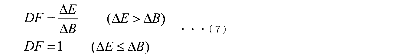
異露光撮像回数算出部13は、前記ダイナミックレンジ推定部10から入力された撮像装置のダイナミックレンジΔBと、前記ダイナミックレンジ算出部12から入力されたシーンのダイナミックレンジΔEとに基づいて、撮像装置のダイナミックレンジΔBを偏移させることでシーンのダイナミックレンジΔEの範囲の画像情報を取得するために必要な撮像装置のダイナミックレンジΔBの範囲の数、即ち必要な異露光撮像画像の枚数(異露光撮像回数DF)を、次の式(7)により算出する。
The different-exposure imaging number calculation unit 13 is based on the dynamic range ΔB of the imaging device input from the dynamic
図2は、シーンのダイナミックレンジΔEと撮像装置のダイナミックレンジΔB及び異露光撮像回数DFとの関係の一例を示す図である。図2は、輝度値の高い範囲から順に、範囲が重ならない様に撮像装置のダイナミックレンジΔBを異露光撮像ごとに偏移させ、シーンのダイナミックレンジΔEより広い輝度範囲の画像情報を得ることを示している。 FIG. 2 is a diagram illustrating an example of the relationship between the dynamic range ΔE of the scene, the dynamic range ΔB of the imaging apparatus, and the number of times of different exposure imaging DF. FIG. 2 shows that the dynamic range ΔB of the imaging apparatus is shifted for each different exposure imaging so that the ranges do not overlap in order from the highest luminance value range, and image information in a luminance range wider than the scene dynamic range ΔE is obtained. Show.
あるいは、前述の異露光撮像回数算出部13による異露光撮像回数DFの算出においては、図3に示す様に重複する輝度範囲Xを含む様に算出してもよい。図3は、シーンのダイナミックレンジΔEと撮像装置のダイナミックレンジΔB及び異露光撮像回数DFとの関係の一例を示す図であり、輝度値の高い範囲から順に、範囲が重なる様に撮像装置のダイナミックレンジΔBを異露光撮像ごとに偏移させ、シーンのダイナミックレンジΔEより広い輝度範囲の画像情報を得ることを示している。この場合、異露光撮像回数DFは、次の式(8)により算出する。
異露光撮像回数算出部13は、こうして算出した異露光撮像回数DFを、撮像設定部3に出力する。撮像設定部3は、この異露光撮像回数算出部13から入力された異露光撮像画像回数DFに基づいて撮像条件(ISO感度、絞り値、シャッター速度)を設定し、撮像制御部2に、その設定した撮像条件を出力する。撮像制御部2は、この撮像設定部3から入力された撮像条件に基づき、撮像部1を制御する。撮像部1は、撮像制御部2の制御下でDF回の異露光撮像を行う。撮像部1は、画像取得部4に、DF回の異露光撮像により得られたDF枚の異露光撮像画像を出力する。
The different exposure imaging number calculation unit 13 outputs the different exposure imaging number DF thus calculated to the
画像取得部4は、それら撮像部1から入力されたDF枚の異露光撮像画像を図示しない画像記憶部に記憶する。画像取得部4は、画像合成部5に、それら記憶したDF枚の異露光撮像画像を出力する。画像合成部5は、それら画像取得部4が出力するDF枚の異露光撮像画像の画像信号に対し、公知の動きベクトルを用いたマッチング処理等で、DF枚の異露光撮像画像の位置合わせをする。次に、画像合成部5は、DF枚の異露光撮像画像の同座標の画素値を合成する画像合成処理を行い、ダイナミックレンジ拡大画像を生成する。合成方法は単純加算でも良いし、次の式(9)の様に、重み付け加算でも良い。
ここで、Iは合成後の画像信号、Iiはi枚目の画像信号、αiは重み付け係数を示す。重み付け加算を行うことにより、単純加算の場合より撮像者が観察するシーンに近い画像を作成することができる。このように、画像合成部5は、例えば、複数枚数の異露光撮像画像を合成してダイナミックレンジ拡大画像を生成するダイナミックレンジ拡大画像生成手段として機能する。また、重み付け加算を行なう場合には、画像合成部5は、例えば、複数枚数の異露光撮像画像の輝度値に基づいて重み付け係数を算出する重み付け算出手段として、及び、前記重み付け係数に基づき複数枚数の異露光撮像画像の重み付け加算を行う加算手段として機能する。画像合成部5は、合成画像記憶部6に、この生成したダイナミックレンジ拡大画像を出力する。合成画像記憶部6は、この画像合成部5から入力されたダイナミックレンジ拡大画像を記憶する。
Here, I is an image signal after synthesis, I i is the i-th image signal, and α i is a weighting coefficient. By performing weighted addition, it is possible to create an image closer to the scene observed by the photographer than in the case of simple addition. Thus, the
該合成画像記憶部6は、階調変換曲線算出部14からの要求に応じて、その階調変換曲線算出部14に、記憶しているダイナミックレンジ拡大画像を出力する。階調変換曲線算出部14は、この合成画像記憶部6から入力されたダイナミックレンジ拡大画像に基づいて、階調変換曲線を算出する。即ち、この階調変換曲線算出部14は、例えば、ダイナミックレンジ拡大画像について階調変換曲線を算出する階調変換曲線算出手段として機能する。この階調変換曲線は、階調変換処理における入力画像輝度値Iinと出力画像輝度値Qとの関係を示す曲線である。図4は、入力及び出力がそれぞれ8ビットの場合の階調変換曲線の一例を示す図である。
The composite
階調変換曲線は、予め作成し、階調変換曲線算出部14内の図示しない記憶手段に記憶し、同じく階調変換曲線算出部14内の図示しない読出し部によって読み出すことで算出することができる。階調変換曲線を予め作成し記憶しておけば、撮影時にはそれを読み出せば良いので、撮像時の処理負荷が軽減される。このように、階調変換曲線算出部14内の図示しない記憶手段は、例えば、撮像装置において予め設定された階調変換曲線を記憶する階調変換曲線記憶手段として機能し、階調変換曲線算出部14内の図示しない読出し部は、例えば、前記階調変換曲線記憶手段より階調変換曲線を読み出す階調変換曲線読出手段として機能する。
The gradation conversion curve is prepared in advance, stored in a storage unit (not shown) in the gradation conversion
あるいは、階調変換曲線は、ダイナミックレンジ拡大画像信号Iから算出しても良い。そのようにダイナミックレンジ拡大画像信号Iから階調変換曲線を算出する場合、階調変換曲線算出部14は、特に図示はしないが、例えば、ヒストグラム算出部、クリッピング部、累積値算出部を備える。
Alternatively, the gradation conversion curve may be calculated from the dynamic range expanded image signal I. When the gradation conversion curve is calculated from the dynamic range expanded image signal I as described above, the gradation conversion
ヒストグラム算出部は、ダイナミックレンジ拡大画像信号Iから、図5(a)に示すようなヒストグラムを算出する。このヒストグラムは、対象とする画像について横軸に画素の輝度値を示し、縦軸に当該輝度値である画素の数又は割合で表される頻度を示す。このように、階調変換曲線算出部14内の図示しないヒストグラム算出部は、例えば、ダイナミックレンジ拡大画像からヒストグラムを算出するヒストグラム算出手段として機能する。
The histogram calculation unit calculates a histogram as shown in FIG. 5A from the dynamic range expanded image signal I. This histogram shows the luminance value of the pixel on the horizontal axis and the frequency expressed by the number or the ratio of the pixels having the luminance value on the vertical axis for the target image. As described above, the histogram calculation unit (not shown) in the gradation conversion
クリッピング部は、図5(a)に破線で示すような所定の頻度をクリップ値としてクリップ処理を行い、図5(b)に示すようなヒストグラムを作成する。このように、階調変換曲線算出部14内の図示しないクリッピング部は、例えば、前記ヒストグラムに対してクリップ処理を行うクリッピング手段として機能する。
The clipping unit performs a clipping process using a predetermined frequency as indicated by a broken line in FIG. 5A as a clip value, and creates a histogram as shown in FIG. Thus, a clipping unit (not shown) in the gradation conversion
累積算出部は、このクリップ処理後のヒストグラムから画素の頻度を累積処理して階調変換曲線を算出する。このように、階調変換曲線算出部14内の図示しない累積算出部は、例えば、前記クリップ処理が行われたヒストグラムの累積値を算出する累積値算出手段として機能する。また、クリップ処理を行なわずに、直接、ヒストグラム算出部で算出したヒストグラムから画素の頻度を累積処理して階調変換曲線を算出するようにしても構わない。図5(c)において、実線は、クリップ処理前のヒストグラムから算出した階調変換曲線を、破線は、クリップ処理後のヒストグラムから算出した階調変換曲線を、それぞれ示している。本実施形態では、図5(c)の実線で示した階調変換曲線と破線で示した階調変換曲線のいずれの階調変換曲線を用いても良い。シーン毎にヒストグラムを用いて階調変換曲線を算出する場合は、予め作成し記憶しておいた階調変換曲線を用いる場合と異なり、シーン毎に適切な階調変換曲線が得られるため、コントラストを強調しすぎない適切な階調変換を行うことができる。
The accumulation calculation unit calculates a gradation conversion curve by accumulating the pixel frequency from the clipped histogram. As described above, the accumulation calculation unit (not shown) in the gradation conversion
一般に階調変換処理の際、例えば図4又は図5(c)に示した階調変換曲線において入力画像輝度値Iinが低い部分で認められる様な、階調変換曲線の傾きが大きい急激な階調変換を行うとノイズが増幅される。そこで本実施形態では、同条件で撮像した複数枚数の画像を合成することで、このノイズの増幅を抑制する。 Generally when the gradation conversion processing, for example, FIG. 4 or FIG. 5 (c) to the input image luminance value I in the tone conversion curve shown is given as found in the lower part, a sharp slope of the tone conversion curve is large When tone conversion is performed, noise is amplified. Therefore, in the present embodiment, this noise amplification is suppressed by combining a plurality of images captured under the same conditions.
ここで、本実施形態で用いるノイズ増幅の抑制方法の原理を簡単に説明する。画像の信号値をS、ノイズをNとすると、2枚の画像を合成した場合の信号値S’及びノイズN’は次の式(10)で表される。
このように、信号値は2倍になるのに対して、ノイズは2倍ではなくてルート2倍の増加に抑えられる。従って、2枚の画像を合成した場合の合成信号のSN比は、次の式(11)の様に算出される。
前記式(11)の右辺第1項は元の1枚の画像信号のSN比と同じであり、同式右辺第2項の分だけ、元の1枚の画像信号のSN比より、2枚の画像を合成した画像信号のSN比の方が高くなる。同様に、より多くの画像を合成した画像は、よりSN比が向上する。 The first term on the right side of the equation (11) is the same as the S / N ratio of the original one image signal, and the S / N ratio of the original one image signal is two by the amount of the second term on the right side of the formula. The S / N ratio of the image signal obtained by synthesizing these images is higher. Similarly, an S / N ratio is further improved in an image obtained by combining more images.
本実施形態では、ダイナミックレンジ拡大画像に対する階調変換処理でノイズが増幅する場合、同露光条件で撮像する複数枚数の画像(以下、「同露光撮像画像」と称する)を合成することでノイズを低減させる。
このため、階調変換曲線算出部14は、増幅率算出部15に、前述の算出した階調変換曲線を出力する。増幅率算出部15は、この階調変換曲線算出部14から入力された階調変換曲線を微分してコントラスト増幅率Rを算出する。このように、増幅率算出部15は、例えば、階調変換曲線からコントラスト増幅率を算出する増幅率算出手段として機能する。ここでコントラスト増幅率Rは、階調変換曲線の微分値であり、階調変換時の入力画像輝度値に対する出力画像輝度値の増幅率を表す。図6は、入力画像輝度値Iinに対するコントラスト増幅率Rの関係の例を示す図である。
In the present embodiment, when noise is amplified by gradation conversion processing for an image with an expanded dynamic range, noise is synthesized by synthesizing a plurality of images (hereinafter referred to as “same exposure captured images”) captured under the same exposure conditions. Reduce.
Therefore, the gradation conversion
増幅率算出部15は、輝度範囲選択部16に、算出したコントラスト増幅率Rを出力する。輝度範囲選択部16は、この増幅率算出部15から入力されたコントラスト増幅率Rに関する閾値Zを設定し、それら入力されたコントラスト増幅率Rと設定した閾値Zとが次の式(12)の条件を満たす時、ノイズが増幅されると判断する。
![]()
![]()
即ち、輝度範囲選択部16は、前記式(12)における条件を満たす輝度範囲を、特定領域Aとして選択する。図7は、これらコントラスト増幅率R及び閾値Zと、特定領域Aとの関係を示す図である。このように、輝度範囲選択部16は、例えば、コントラスト増幅率に基づいて、ダイナミックレンジ拡大画像における特定の輝度範囲を選択する輝度範囲選択手段として機能する。即ち、輝度範囲選択部16は、例えば、コントラスト増幅率における閾値を設定する閾値設定手段と、前記コントラスト増幅率と前記閾値とを比較してダイナミックレンジ拡大画像における特定の輝度範囲を選択する選択手段としての機能を果たす。
That is, the luminance
この時、輝度範囲選択部16は、露光条件読出部18を介して記憶手段としての露光条件記憶部17から、前記特定領域Aに対応する輝度範囲撮像時の絞り値、シャッター速度、ISO感度等の露光条件に関わる設定値を読み出す。即ち、露光条件記憶部17は、露光条件読出部18の要求に応じて、その露光条件読出部18に対し記憶している露光条件を出力し、露光条件読出部18は、この露光条件記憶部17から入力された露光条件を輝度範囲選択部16に出力する。このように、露光条件記憶部17は、例えば、異露光撮像画像のそれぞれの撮像時の露光条件を記憶する露光条件記憶手段として機能し、露光条件読出部18は、例えば、前記輝度範囲に対応する露光条件を露光条件記憶手段より読み出す露光条件読出手段として機能する。
At this time, the brightness
また、輝度範囲選択部16は、合成画像記憶部6に記憶された前記ダイナミックレンジ拡大画像を読み出し、下記の様にダイナミックレンジ拡大画像におけるノイズ量を算出し、これを用いて特定領域Aを選択しても良い。
この場合、輝度範囲選択部16は、図8に示す通り、バッファ部20と、局所領域抽出部21と、ノイズ量算出部22と、算出部23と、輝度範囲特定部24とにより構成する。
Further, the luminance
In this case, the luminance
バッファ部20は、合成画像記憶部6から入力される前記ダイナミックレンジ拡大画像信号Iを記憶する。該バッファ部20は、局所領域抽出部21の要求に応じて、その局所領域抽出部21に、記憶しているダイナミックレンジ拡大画像信号Iを出力する。局所領域抽出部21は、そのバッファ部20から入力されたダイナミックレンジ拡大画像信号Iから、注目画素を中心とする例えば5×5の局所領域を抽出する。この局所領域の抽出は、ダイナミックレンジ拡大画像I全体に対して行っても良いし、指定された領域についてのみ行っても良い。局所領域抽出部21は、ノイズ量算出部22に、抽出した局所領域の情報を出力する。ノイズ量算出部22は、その局所領域抽出部21から入力された局所領域の情報を用いて、ノイズ量を算出する。ある注目画素νにおけるノイズ量Nνは、例えば局所領域における信号の平均値Sνに対する関数として、次の式(13)により算出する。
![]()
![]()
前記式(13)の関数以外にも、ノイズ量Nνは、入力信号に対するノイズ量についてルックアップテーブル(LUT)を用いて算出しても良いし、局所領域の信号に対する標準偏差をノイズ量Nνとしても良い。 In addition to the function of the equation (13), the noise amount N ν may be calculated by using a look-up table (LUT) for the noise amount with respect to the input signal, and the standard deviation with respect to the signal in the local region is calculated as the noise amount N. It may be v .
ノイズ量算出部22は、ダイナミックレンジ拡大画像I全体又は指定された領域の各画素を注目画素としてそれぞれに対して前記処理を行い、算出部23に、算出した画素毎のノイズ量を出力する。算出部23は、そのノイズ量算出部22から入力された画素毎のノイズ量用いて、当該ダイナミックレンジ拡大画像信号全体のノイズ量Noiを次の式(14)により算出する。
ここで、Mは総画素数を表す。ダイナミックレンジ拡大画像信号全体のノイズ量Noiを算出するにあたっては、前記式(14)の単純加算以外にも、領域による重み付け加算を用いても良い。このように、局所領域抽出部21、ノイズ量算出部22及び算出部23は、例えば、ダイナミックレンジ拡大画像からノイズ量を算出するノイズ量算出手段として機能する。即ち、局所領域抽出部21は、例えば、ダイナミックレンジ拡大画像の注目画素を中心とする局所領域を抽出する局所領域抽出手段として機能し、ノイズ量算出部22は、例えば、局所領域中の画像に対してノイズ量を算出する局所領域ノイズ量算出手段として機能し、算出部23は、例えば、局所領域中のノイズ量を用いて前記ダイナミックレンジ拡大画像全体のノイズ量を算出する算出手段として機能する。
Here, M represents the total number of pixels. In calculating the noise amount Noi of the entire dynamic range expanded image signal, in addition to the simple addition of the equation (14), weighted addition by region may be used. Thus, the local
算出部23は、輝度範囲特定部24に、算出したノイズ量Noiを出力する。輝度範囲特定部24は、前記増幅率算出部15から入力されたコントラスト増幅率R、前記算出部23から入力されたノイズ量Noi及び閾値Lを用いて次の式(15)の条件を満たす時、ノイズが増幅されると判断する。
![]()
![]()
即ち、輝度範囲特定部24は、前記式(15)における条件を満たす輝度範囲を、特定領域Aとして選択する。図9は、コントラスト増幅率Rとノイズ量Noiとの積及び図示しない輝度範囲選択部16内の閾値設定部が設定する閾値Lと、特定領域Aとの関係を示す図である。このように、輝度範囲特定部24は、例えば、閾値を設定する閾値設定手段として、及び、前記コントラスト増幅率及び前記ノイズ量を用いて算出した値と、前記閾値とを比較してダイナミックレンジ拡大画像における特定の輝度範囲を選択する選択手段として機能する。
That is, the luminance
輝度範囲選択部16は、同露光撮像回数算出部19に、選択された特定領域Aの輝度範囲情報を出力する。同露光撮像回数算出部19は、この輝度範囲選択部16から入力された特定領域Aの輝度範囲情報に基づき、前記輝度範囲の露光条件で行う同露光撮像の回数を算出する。このように、同露光撮像回数算出部19は、前記輝度範囲、前記コントラスト増幅率及び前記輝度範囲に対応する露光条件に基づいて、同露光撮像回数を算出する同露光撮像回数算出手段として機能する。
The luminance
図10は、閾値Zを設定しコントラスト増幅率Rより特定される特定領域Aの輝度範囲の露光条件で行う同露光撮像画像回数PFの算出方法の例を示す図である。同露光撮像回数算出部19は、前記増幅率算出部15よりコントラスト増幅率Rを取得し、同露光撮像回数算出部19内の図示しない代表輝度値算出部は、前記特定領域Aの輝度範囲における入力画像輝度値の平均値である代表輝度値IAを算出し、同露光撮像回数算出部19内の図示しない代表輝度値増幅率算出部は、代表輝度値IAに対応するコントラスト増幅率RAを用いて、同露光撮像回数PFを次の式(16)により算出する。
ここで、C1及びC2はそれぞれ定数であり、撮像装置の構成によって設定される整数である。本実施形態においてはC1=C2=1とする。同露光撮像回数算出部19は、撮像設定部3に、こうして算出した同露光撮像回数PFを出力する。このように、同露光撮像回数算出部19内の図示しない代表輝度値算出部は、例えば、前記特定輝度範囲から代表輝度値を算出する代表輝度値算出手段として機能し、同じく同露光撮像回数算出部19内の図示しない代表輝度値増幅率算出部は、例えば、前記代表輝度値に対する増幅率を算出する代表輝度値増幅率算出手段として機能する。
Here, C 1 and C 2 are constants and are integers set by the configuration of the imaging apparatus. In the present embodiment, C 1 = C 2 = 1. The same exposure imaging
撮像設定部3は、同露光撮像を行う特定領域Aの露光条件を、露光条件読出部18を介して前記露光条件記憶部17から読み出す。即ち、露光条件記憶部17は、露光条件読出部18の要求に応じて、その露光条件読出部18に対し記憶している同露光撮像を行う特定領域Aの露光条件を出力し、露光条件読出部18は、その露光条件記憶部17が出力する同露光撮像を行う特定領域Aの露光条件を撮像設定部3に出力する。撮像設定部3は、この露光条件読出部18からの入力される特定領域Aの露光条件と、前記同露光撮像回数算出部19から入力される同露光撮像回数PFとを合わせて撮像条件を設定する。撮像設定部3は、撮像制御部2に、その設定した撮像条件を出力する。撮像制御部2は、その撮像設定部3から入力された撮像条件に基づき、撮像部1を制御する。撮像部1は、撮像制御部2の制御下でPF回の同露光撮像を行う。以上の処理により、前記コントラスト増幅率に基づいて選択された前記ダイナミックレンジ拡大画像における特定の輝度範囲に対応する異露光撮像における露光条件を用いて、PF回の同露光撮像を行う。
The
撮像部1は、画像取得部4に、PF回の同露光撮像により得られるPF枚の同露光撮像画像を出力する。画像取得部4は、これらの撮像部1から入力されるPF枚の同露光撮像画像を図示しない画像記憶部に記憶する。このように、撮像部1、撮像制御部2、撮像設定部3及び画像取得部4は、例えば、前記輝度範囲に対応する露光条件を用いて複数回数の同露光撮像を行って複数枚数の同露光撮像画像を取得する同露光画像取得手段として機能する。
The
この時、図11に示す例のように、前記特定領域Aが撮像装置のダイナミックレンジΔB以上であり複数の露光条件A1及びA2を含むものであった場合には、前記算出された同露光撮像回数PFについて、例えば、露光条件A1について入力画像輝度値の代表輝度値IA1を、露光条件A2について入力画像輝度値の代表輝度値IA2をそれぞれ算出し、代表輝度値IA1及びIA2にそれぞれ対応するコントラスト増幅率RA1及びRA2を用いて、次の式(17)の様に、前記同露光撮像回数PFを複数露光条件の数H各々に適宜割り振り、露光条件A1でPF1回(図11の例では3回)、露光条件A2でPF2回(図11の例では2回)の撮像を行っても良い。この割り振りは、撮像装置の構成によって設定される。
画像取得部4は、画像合成部5に、記憶したPF枚の同露光撮像画像を出力する。また、前記合成画像記憶部6は、画像合成部5に、記憶しているダイナミックレンジ拡大画像を出力する。画像合成部5は、それら画像取得部4から入力されたPF枚の同露光撮像画像の画像信号と、合成画像記憶部6から入力されたダイナミックレンジ拡大画像との合成画像を生成する。このように、画像合成部5は、例えば、ダイナミックレンジ拡大画像に複数枚数の同露光撮像画像を合成して合成画像を生成する画像合成手段として機能する。
The
画像合成部5は、階調変換部7に、その生成した前記PF枚の同露光撮像画像とダイナミックレンジ拡大画像との合成画像を出力する。また、前記階調変換曲線算出部14は、階調変換部7に、算出したダイナミックレンジ拡大画像に対して適正な階調変換曲線を出力する。階調変換部7は、その階調変換曲線算出部14から入力された階調変換曲線に基づいて、画像合成部5から入力された前記合成画像の階調変換処理を行う。そして、階調変換部7は、最終的なダイナミックレンジ拡大画像として、この階調変換された合成画像を出力する。このように、階調変換部7は、例えば、合成画像に対し階調変換曲線に基づき階調変換を行う階調変換手段として機能する。
The
このダイナミックレンジが拡大され階調変換された階調変換部7からの出力画像は、図示しない記録媒体に記録されたり、図示しないインタフェースを介して表示装置や印刷装置等の外部出力装置で出力されたり、あるいは図示しないインタフェースを介してネットワーク上の記憶装置等に記憶されたりすることができる。
The output image from the
以上のような本実施形態に係る撮像装置によれば、露光量が異なる複数枚数の画像を合成し生成されるダイナミックレンジ拡大画像において、コントラスト増幅率Rが高い特定領域AについてPF枚の同露光撮像画像を取得して合成することで、少ない撮像枚数により、階調変換処理により増幅されるノイズの影響を低減させることができ、撮像者が観察するシーンと同様に広いダイナミックレンジを有しかつノイズが少ない画像を提供することができる。 According to the imaging apparatus according to the present embodiment as described above, in the dynamic range expansion image generated by synthesizing a plurality of images having different exposure amounts, the same exposure of PF sheets for the specific area A having a high contrast amplification factor R. By acquiring and synthesizing the captured images, the effect of noise amplified by the gradation conversion process can be reduced with a small number of captured images, and it has a wide dynamic range similar to the scene observed by the photographer and An image with less noise can be provided.
また、図7を参照して説明した通り、コントラスト増幅率Rに基づいて、ノイズが増幅される特定領域Aを決定することで、ノイズ増幅が懸念される輝度範囲を高精度に選択することができる。さらに、図8及び9を参照して説明した通り、ノイズ量を算出しこれを用いて特定領域Aを決定することで、ノイズ増幅が懸念される輝度範囲をさらに高精度に選択することができる。この時、局所領域毎のノイズ量を算出することにより、各画素のノイズ量を正確に算出することができる。 Further, as described with reference to FIG. 7, by determining the specific region A in which noise is amplified based on the contrast amplification factor R, it is possible to select a luminance range in which noise amplification is a concern with high accuracy. it can. Furthermore, as described with reference to FIGS. 8 and 9, by calculating the amount of noise and using this to determine the specific area A, it is possible to select a luminance range in which noise amplification is a concern with higher accuracy. . At this time, the noise amount of each pixel can be accurately calculated by calculating the noise amount for each local region.
また、特定領域Aに含まれる輝度を撮影した露光条件についてのみ同露光撮像を行うことによって、異露光撮像時の異なる露光条件の個々について同露光撮像を行う場合に比し撮像回数及び得られた画像の処理を低減することができる。前記同露光撮像を実行するために、露光条件は露光条件記憶部17に記憶され、その条件は露光条件読出部18を介して読み出される。
In addition, by performing the same exposure imaging only for the exposure conditions in which the luminance included in the specific area A is captured, the number of times and the number of imaging were obtained compared to the case where the same exposure imaging was performed for each of the different exposure conditions during the different exposure imaging. Image processing can be reduced. In order to execute the same exposure imaging, the exposure condition is stored in the exposure
尚、本発明は前記実施形態そのままに限定されるものではなく、実施段階ではその要旨を逸脱しない範囲で構成要素を変形して具体化できる。また、前記実施形態に開示されている複数の構成要素の適宜な組み合わせにより、種々の発明を形成できる。例えば、実施形態に示される全構成要素から幾つかの構成要素を削除しても、発明が解決しようとする課題の欄で述べられた課題が解決でき、かつ、発明の効果が得られる場合には、この構成要素が削除された構成も発明として抽出され得る。 Note that the present invention is not limited to the above-described embodiment as it is, and can be embodied by modifying the constituent elements without departing from the scope of the invention in the implementation stage. Moreover, various inventions can be formed by appropriately combining a plurality of constituent elements disclosed in the embodiment. For example, even if some constituent elements are deleted from all the constituent elements shown in the embodiment, the problem described in the column of problems to be solved by the invention can be solved and the effect of the invention can be obtained. The configuration in which this component is deleted can also be extracted as an invention.
1…撮像部、2…撮像制御部、3…撮像設定部、4…画像取得部、5…画像合成部、6…合成画像記憶部、7…階調変換部、8…異露光撮像設定部、9…同露光撮像設定部、10…ダイナミックレンジ推定部、11…シーン輝度取得部、12…ダイナミックレンジ算出部、13…異露光撮像回数算出部、14…階調変換曲線算出部、15…増幅率算出部、16…輝度範囲選択部、17…露光条件記憶部、18…露光条件読出部、19…同露光撮像回数算出部、20…バッファ部、21…局所領域抽出部、22…ノイズ量算出部、23…算出部、24…輝度範囲特定部。
DESCRIPTION OF
Claims (10)
前記異露光撮像画像のそれぞれの撮像時の露光条件を記憶する露光条件記憶手段と、
前記複数枚数の異露光撮像画像を合成してダイナミックレンジ拡大画像を生成するダイナミックレンジ拡大画像生成手段と、
前記ダイナミックレンジ拡大画像について階調変換曲線を算出する階調変換曲線算出手段と、
前記階調変換曲線からコントラスト増幅率を算出する増幅率算出手段と、
前記コントラスト増幅率に基づいて、前記ダイナミックレンジ拡大画像における特定の輝度範囲を選択する輝度範囲選択手段と、
前記輝度範囲に対応する露光条件を前記露光条件記憶手段より読み出す露光条件読出手段と、
前記輝度範囲、前記コントラスト増幅率及び前記輝度範囲に対応する露光条件に基づいて、同露光撮像回数を算出する同露光撮像回数算出手段と、
前記輝度範囲に対応する露光条件を用いて複数回数の同露光撮像を行って複数枚数の同露光撮像画像を取得する同露光画像取得手段と、
前記ダイナミックレンジ拡大画像に前記複数枚数の同露光撮像画像を合成して合成画像を生成する画像合成手段と、
前記合成画像に対し前記階調変換曲線に基づき階調変換を行う階調変換手段と、
を備えることを特徴とする撮像装置。 Different exposure image acquisition means for performing different exposure imaging with different exposure conditions a plurality of times to acquire a plurality of different exposure captured images;
Exposure condition storage means for storing an exposure condition at the time of capturing each of the different exposure captured images;
A dynamic range expansion image generation means for generating a dynamic range expansion image by combining the plurality of different exposure captured images;
A gradation conversion curve calculating means for calculating a gradation conversion curve for the dynamic range expanded image;
An amplification factor calculating means for calculating a contrast amplification factor from the gradation conversion curve;
Luminance range selection means for selecting a specific luminance range in the dynamic range expanded image based on the contrast amplification factor;
Exposure condition reading means for reading exposure conditions corresponding to the brightness range from the exposure condition storage means;
Based on the brightness range, the contrast amplification factor, and an exposure condition corresponding to the brightness range, the same exposure imaging number calculation means for calculating the same exposure imaging number;
Same exposure image acquisition means for acquiring a plurality of same exposure captured images by performing a plurality of times of same exposure imaging using an exposure condition corresponding to the brightness range;
Image combining means for generating a combined image by combining the plurality of the same exposure captured images with the dynamic range expanded image;
Gradation conversion means for performing gradation conversion on the composite image based on the gradation conversion curve;
An imaging apparatus comprising:
前記コントラスト増幅率における閾値を設定する閾値設定手段と、
前記コントラスト増幅率と前記閾値とを比較して前記ダイナミックレンジ拡大画像における特定の輝度範囲を選択する選択手段と、
を備えることを特徴とする請求項1に記載の撮像装置。 The luminance range selection means includes
Threshold setting means for setting a threshold for the contrast amplification factor;
A selection means for comparing the contrast amplification factor and the threshold to select a specific luminance range in the dynamic range expanded image;
The imaging apparatus according to claim 1, further comprising:
閾値を設定する閾値設定手段と、
前記ダイナミックレンジ拡大画像からノイズ量を算出するノイズ量算出手段と、
前記コントラスト増幅率及び前記ノイズ量を用いて算出した値と、前記閾値とを比較して前記ダイナミックレンジ拡大画像における特定の輝度範囲を選択する選択手段と、
を備えることを特徴とする請求項1に記載の撮像装置。 The luminance range selection means includes
Threshold setting means for setting a threshold;
A noise amount calculating means for calculating a noise amount from the dynamic range enlarged image;
A selection means for selecting a specific luminance range in the dynamic range expanded image by comparing the threshold value with a value calculated using the contrast amplification factor and the noise amount;
The imaging apparatus according to claim 1, further comprising:
前記ダイナミックレンジ拡大画像の注目画素を中心とする局所領域を抽出する局所領域抽出手段と、
前記局所領域中の画像に対してノイズ量を算出する局所領域ノイズ量算出手段と、
前記局所領域中のノイズ量を用いて前記ダイナミックレンジ拡大画像全体のノイズ量を算出する算出手段と、
を備えることを特徴とする請求項3に記載の撮像装置。 The noise amount calculating means includes
A local region extracting means for extracting a local region centered on the target pixel of the dynamic range expanded image;
A local area noise amount calculating means for calculating a noise amount for an image in the local area;
A calculation means for calculating a noise amount of the entire dynamic range expanded image using a noise amount in the local region;
The imaging apparatus according to claim 3, further comprising:
前記撮像装置において予め設定された階調変換曲線を記憶する階調変換曲線記憶手段と、
前記階調変換曲線記憶手段より階調変換曲線を読み出す階調変換曲線読出手段と、
を備えることを特徴とする請求項1に記載の撮像装置。 The gradation conversion curve calculation means includes:
Gradation conversion curve storage means for storing a gradation conversion curve set in advance in the imaging apparatus;
Gradation conversion curve reading means for reading out the gradation conversion curve from the gradation conversion curve storage means;
The imaging apparatus according to claim 1, further comprising:
前記ダイナミックレンジ拡大画像からヒストグラムを算出するヒストグラム算出手段と、
前記ヒストグラムに対してクリップ処理を行うクリッピング手段と、
前記クリップ処理が行われたヒストグラムの累積値を算出する累積値算出手段と、
を備えることを特徴とする請求項1に記載の撮像装置。 The gradation conversion curve calculation means includes:
A histogram calculating means for calculating a histogram from the dynamic range expanded image;
Clipping means for performing clip processing on the histogram;
A cumulative value calculating means for calculating a cumulative value of the histogram subjected to the clip processing;
The imaging apparatus according to claim 1, further comprising:
前記複数枚数の異露光撮像画像の輝度値に基づいて重み付け係数を算出する重み付け算出手段と、
前記重み付け係数に基づき前記複数枚数の異露光撮像画像の重み付け加算を行う加算手段と、
を備えることを特徴とする請求項1に記載の撮像装置。 The dynamic range expanded image generation means includes
A weighting calculating means for calculating a weighting coefficient based on a luminance value of the plurality of different-exposure captured images;
Adding means for performing weighted addition of the plurality of different exposure captured images based on the weighting coefficient;
The imaging apparatus according to claim 1, further comprising:
前記特定輝度範囲から代表輝度値を算出する代表輝度値算出手段と、
前記代表輝度値に対する増幅率を算出する代表輝度値増幅率算出手段と、
を備え、
前記同露光撮像回数算出手段は、前記代表輝度値及び前記代表輝度値に対する増幅率を用いて同露光撮像回数を算出する
ことを特徴とする請求項1に記載の撮像装置。 The same exposure image acquisition means,
Representative luminance value calculating means for calculating a representative luminance value from the specific luminance range;
Representative luminance value amplification factor calculating means for calculating an amplification factor for the representative luminance value;
With
The imaging apparatus according to claim 1, wherein the same-exposure imaging number calculation unit calculates the same-exposure imaging number using the representative luminance value and an amplification factor for the representative luminance value.
前記異露光撮像画像撮像時の露光条件を記憶手段に記憶し、
前記複数枚数の異露光撮像画像を合成してダイナミックレンジ拡大画像を生成し、
前記ダイナミックレンジ拡大画像について階調変換曲線を算出し、
前記階調変換曲線からコントラスト増幅率を算出し、
前記コントラスト増幅率に基づいて、前記ダイナミックレンジ拡大画像における特定の輝度範囲を選択し、
前記輝度範囲に対応する露光条件を前記記憶手段より読み出し、
前記輝度範囲、前記コントラスト増幅率及び前記輝度範囲に対応する露光条件に基づいて、同露光撮像回数を算出し、
前記撮像手段によって前記輝度範囲に対応する露光条件を用いて複数回数の同露光撮像を行って複数枚数の同露光撮像画像を取得し、
前記ダイナミックレンジ拡大画像に前記複数枚数の同露光撮像画像を合成して合成画像を生成し、
前記合成画像に対し前記階調変換曲線に基づき階調変換を行う
ことを特徴とする撮像方法。 A plurality of different-exposure captured images are obtained by performing a plurality of different-exposure imaging with different exposure conditions by the imaging means,
Storing the exposure condition at the time of capturing the different exposure captured image in a storage means;
A dynamic range expansion image is generated by combining the plurality of different exposure captured images,
Calculating a gradation conversion curve for the dynamic range expanded image;
Calculate the contrast amplification factor from the gradation conversion curve,
Based on the contrast amplification factor, select a specific luminance range in the dynamic range expansion image,
Read the exposure conditions corresponding to the luminance range from the storage means,
Based on the exposure range corresponding to the brightness range, the contrast amplification factor and the brightness range, the number of exposure exposure imaging,
A plurality of times of the same exposure imaging is performed by using the exposure means corresponding to the luminance range by the imaging means to obtain a plurality of the same exposure captured images,
Combining the plurality of same-exposure captured images with the dynamic range expanded image to generate a combined image;
An imaging method, wherein gradation conversion is performed on the composite image based on the gradation conversion curve.
Priority Applications (1)
| Application Number | Priority Date | Filing Date | Title |
|---|---|---|---|
| JP2010067013A JP2011199785A (en) | 2010-03-23 | 2010-03-23 | Imaging apparatus and method |
Applications Claiming Priority (1)
| Application Number | Priority Date | Filing Date | Title |
|---|---|---|---|
| JP2010067013A JP2011199785A (en) | 2010-03-23 | 2010-03-23 | Imaging apparatus and method |
Publications (1)
| Publication Number | Publication Date |
|---|---|
| JP2011199785A true JP2011199785A (en) | 2011-10-06 |
Family
ID=44877376
Family Applications (1)
| Application Number | Title | Priority Date | Filing Date |
|---|---|---|---|
| JP2010067013A Withdrawn JP2011199785A (en) | 2010-03-23 | 2010-03-23 | Imaging apparatus and method |
Country Status (1)
| Country | Link |
|---|---|
| JP (1) | JP2011199785A (en) |
Cited By (5)
| Publication number | Priority date | Publication date | Assignee | Title |
|---|---|---|---|---|
| JP2013175827A (en) * | 2012-02-23 | 2013-09-05 | Canon Inc | Image pickup device and control method and program thereof, and recording medium |
| JP2016058890A (en) * | 2014-09-09 | 2016-04-21 | ハンファテクウィン株式会社Hanwha Techwin Co.,Ltd. | Image processing apparatus and image processing method |
| JP2016058889A (en) * | 2014-09-09 | 2016-04-21 | ハンファテクウィン株式会社Hanwha Techwin Co.,Ltd. | Image processing apparatus and image processing method |
| JP2019219495A (en) * | 2018-06-19 | 2019-12-26 | 信越化学工業株式会社 | Evaluation method of photomask blank-related substrate |
| CN111798519A (en) * | 2020-07-21 | 2020-10-20 | 广东博智林机器人有限公司 | Method and device for extracting laser stripe center, electronic equipment and storage medium |
-
2010
- 2010-03-23 JP JP2010067013A patent/JP2011199785A/en not_active Withdrawn
Cited By (7)
| Publication number | Priority date | Publication date | Assignee | Title |
|---|---|---|---|---|
| JP2013175827A (en) * | 2012-02-23 | 2013-09-05 | Canon Inc | Image pickup device and control method and program thereof, and recording medium |
| JP2016058890A (en) * | 2014-09-09 | 2016-04-21 | ハンファテクウィン株式会社Hanwha Techwin Co.,Ltd. | Image processing apparatus and image processing method |
| JP2016058889A (en) * | 2014-09-09 | 2016-04-21 | ハンファテクウィン株式会社Hanwha Techwin Co.,Ltd. | Image processing apparatus and image processing method |
| JP2019219495A (en) * | 2018-06-19 | 2019-12-26 | 信越化学工業株式会社 | Evaluation method of photomask blank-related substrate |
| CN110618582A (en) * | 2018-06-19 | 2019-12-27 | 信越化学工业株式会社 | Evaluation method of photomask blank related substrate |
| JP7017475B2 (en) | 2018-06-19 | 2022-02-08 | 信越化学工業株式会社 | Photomask blank-related evaluation method of surface condition of substrate |
| CN111798519A (en) * | 2020-07-21 | 2020-10-20 | 广东博智林机器人有限公司 | Method and device for extracting laser stripe center, electronic equipment and storage medium |
Similar Documents
| Publication | Publication Date | Title |
|---|---|---|
| JP5713752B2 (en) | Image processing apparatus and control method thereof | |
| KR101247646B1 (en) | Image combining apparatus, image combining method and recording medium | |
| JP5408053B2 (en) | Image processing apparatus and image processing method | |
| JP5719418B2 (en) | High dynamic range image exposure time control method | |
| JP5672796B2 (en) | Image processing apparatus and image processing method | |
| JP6478499B2 (en) | Image processing apparatus, image processing method, and program | |
| WO2013032008A1 (en) | Image processing device and program | |
| JP6312487B2 (en) | Image processing apparatus, control method therefor, and program | |
| JP4818393B2 (en) | Image processing method and image processing apparatus | |
| JP4479527B2 (en) | Image processing method, image processing apparatus, image processing program, and electronic camera | |
| JP2014179756A (en) | Image processing device, control method therefor and control program | |
| JP2019047169A (en) | Apparatus, method, and program for generating high dynamic range image | |
| JP2011199785A (en) | Imaging apparatus and method | |
| JP6611543B2 (en) | Image processing apparatus, image processing method, and program | |
| CN106575434B (en) | Image processing apparatus, imaging apparatus, and image processing method | |
| JP2008294524A (en) | Image processor and image processing method | |
| JP2020145553A (en) | Image processing apparatus, image processing method and program | |
| JP5365881B2 (en) | Image processing apparatus and image processing method | |
| JP5693099B2 (en) | Image processing apparatus, image processing method, radiation imaging system, and program | |
| KR102282464B1 (en) | Image processing apparatus and image processing method | |
| JP2016127388A (en) | Image processing system, control method of the same, program, and storage medium | |
| JP2008219230A (en) | Imaging apparatus, and image processing method | |
| JP4802333B2 (en) | Method for determining exposure ratio in image composition | |
| JP2011199787A (en) | Image processing apparatus and image processing method | |
| KR102170697B1 (en) | Image processing apparatus and image processing method |
Legal Events
| Date | Code | Title | Description |
|---|---|---|---|
| A300 | Application deemed to be withdrawn because no request for examination was validly filed |
Free format text: JAPANESE INTERMEDIATE CODE: A300 Effective date: 20130604 |