JP4265750B2 - Cleaning device, process cartridge, and image forming apparatus - Google Patents
Cleaning device, process cartridge, and image forming apparatus Download PDFInfo
- Publication number
- JP4265750B2 JP4265750B2 JP2003119928A JP2003119928A JP4265750B2 JP 4265750 B2 JP4265750 B2 JP 4265750B2 JP 2003119928 A JP2003119928 A JP 2003119928A JP 2003119928 A JP2003119928 A JP 2003119928A JP 4265750 B2 JP4265750 B2 JP 4265750B2
- Authority
- JP
- Japan
- Prior art keywords
- image
- cleaning blade
- toner
- forming apparatus
- cleaning
- Prior art date
- Legal status (The legal status is an assumption and is not a legal conclusion. Google has not performed a legal analysis and makes no representation as to the accuracy of the status listed.)
- Expired - Fee Related
Links
Images
Landscapes
- Developing Agents For Electrophotography (AREA)
- Cleaning In Electrography (AREA)
- Control Or Security For Electrophotography (AREA)
Description
【0001】
【発明の属する技術分野】
この発明は、例えば、複写機、プリンタ、ファクシミリ、またはそれらの複合機などの、用紙・OHPフィルム等のシートに画像を形成する画像形成装置に関する。および、そのような画像形成装置に備え、画像転写後の像担持体をクリーニングするクリーニング装置に関する。および、そのようなクリーニング装置と、少なくとも像担持体とを備え、画像形成装置に対して一括して着脱自在とするプロセスカートリッジに関する。
【0002】
【従来の技術】
従来、電子写真方式の画像形成装置では、例えば帯電、書込みを行って像担持体に静電潜像を形成し、その静電潜像にトナーを付着して現像することにより可視像化し、その可視像化することにより形成した像担持体上のトナー画像を用紙に転写して画像を形成していた。そして、その画像転写後の用紙を、定着装置を通すことにより、未定着転写画像を用紙に定着する一方、画像転写後の像担持体を、クリーニング装置でクリーニングしていた。
【0003】
ところで、この種の画像形成装置で用いるクリーニング装置には、クリーニングブレードを備え、そのクリーニングブレードをドラム状の像担持体に所定の圧力で押し当てて、画像転写後の像担持体をクリーニングするものがあった。
【0004】
しかし、このようなクリーニング装置を備える画像形成装置は、像担持体とクリーニングブレードとの間に異物を挟み込むことなどにより、クリーニング不良を発生して、形成した画像に縦スジ状の汚れを発生して、画像品質が低下する問題があった。
【0005】
【特許文献1】
特開平10−186989号公報
【特許文献2】
特開平11−219088号公報
そこで、その問題を解決するため、従来の画像形成装置には、例えば、特許文献1、特許文献2などに記載される技術があった。それらの文献に記載されているクリーニング装置は、画像形成時、像担持体の回転とともに、クリーニングブレードを像担持体の幅方向に一定幅で揺動することにより異物を除去して、クリーニング不良の発生を防止し、画像品質が低下することを防止していた。
【0006】
【発明が解決しようとする課題】
しかし、例えば、画像形成装置を設置して後はじめて使用する場合、または小サイズの画像を連続して形成した場合など、像担持体上の残留トナーの堆積量に偏差があったとき、クリーニングブレードと像担持体との間に摩擦力が大きい個所と小さい個所とができてしまう。このような摩擦力の大きさに偏差がある状態で、クリーニングブレードを揺動すると、摩擦力が大きい個所で、クリーニングブレードのエッジが劣化して、早期にクリーニング性能が低下して画像品質が低下するとともに、像担持体の表面に偏摩耗が発生して、画像品質が低下する問題があった。
【0007】
そこで、この発明の第1の目的は、クリーニングブレードのエッジや像担持体の表面が早期に劣化することを防止しながら、クリーニング性能を長期間維持して、画像品質の低下を防止することにある。
【0008】
ところで、従来、定着の際に発生するオフセットを防止することを主な目的として、画像形成装置に用いるトナーに、ワックスを添加したものがあった。
【0009】
トナーからのワックス染み出し量は、温度が低い場合は少なく、高い場合は多い。また、ワックス染み出し量が多いほど、オフセットの発生を確実に防止することができる。
【0010】
しかし、トナーからのワックス染み出し量が多くなり、前述した例の場合と同様に、像担持体上の残留トナーの堆積量に偏差があった場合、ワックスにより、摩擦力の偏差が一層大きくなってしまう。よって、前述した問題が、一層悪化してしまう課題があった。
【0011】
そこで、この発明の第2の目的は、特にクリーニングブレードのエッジが早期に劣化したり、像担持体の表面に偏摩耗が発生したりしやすい、ワックスを添加したトナーを用いる画像形成装置に備えるクリーニング装置において、クリーニングブレードのエッジや像担持体の表面が早期に劣化することを防止しながら、クリーニング性能を長期間維持して、画像品質の低下を防止することにある。
【0012】
この発明の第3の目的は、上述した目的を達成したクリーニング装置を備えるとともに、メンテナンス性を向上したプロセスカートリッジを提供することにある。
【0013】
この発明の第4の目的は、第1または第2の目的を達成したクリーニング装置を備える画像形成装置を提供することにある。
【0014】
この発明の第5の目的は、第3の目的を達成したプロセスカートリッジを備える画像形成装置を提供することにある。
【0015】
ところで、所定時間あたりの画像形成枚数が同じであるとき、画像形成装置が備える像担持体の直径が小さいと、像担持体の回転数が多くなる。よって、直径が小さい像担持体を用いると、それだけ像担持体やクリーニングブレードの上述した偏摩耗が大きくなる。
【0016】
そこで、この発明の第6の目的は、特にクリーニングブレードのエッジが早期に劣化したり、像担持体の表面に偏摩耗が発生したりしやすい、直径の小さい像担持体を用いる画像形成装置において、クリーニングブレードのエッジや像担持体の表面が早期に劣化することを防止しながら、クリーニング性能を長期間維持して、画像品質の低下を防止することにある。
【0017】
さて、ワックスを添加したトナーを用いる画像形成装置において、ワックスの添加量を少なくすると、定着の際にオフセットが発生する問題がある。一方、ワックスの添加量を多くすると、トナー帯電量が低下したり、クリーニングブレードのエッジや像担持体の表面に偏摩耗が発生したりして、画像品質が低下する問題があった。
【0018】
そこで、この発明の第7の目的は、ワックスを添加したトナーを用いる画像形成装置において、定着の際に発生するオフセットを防止するとともに、トナー帯電量の低下を防止し、クリーニングブレードのエッジや像担持体の表面が早期に劣化することを防止しながら、クリーニング性能を長期間維持して、画像品質の低下を防止することにある。
【0019】
また、従来、トナーの中には、低温で定着可能なものがあった。そのトナーは、平均粒径10μm以下であり、少なくとも結着樹脂および着色剤を含有し、テトラヒドロフラン(THF)可溶分により求められたゲルパミエーションクロマトグラフィー(GPC)による分子量分布の値が1,000〜10,000の間に少なくとも1つのピークを有し、分子量分布の半値幅が15,000以下であった。そして、このトナーに、わずかな熱や圧力が加えられた場合でも、ワックスが染み出た。
【0020】
しかし、前述した例の場合と同様に、像担持体上の残留トナーの堆積量に偏差があった場合、トナーから染み出たワックスにより、摩擦力の偏差が一層大きくなってしまう。よって、前述した問題が、一層悪化してしまう課題があった。
【0021】
そこで、この発明の第8の目的は、特にクリーニングブレードのエッジが早期に劣化したり、像担持体の表面に偏摩耗が発生したりしやすい、いわゆる低温定着トナーを使用する画像形成装置において、クリーニングブレードのエッジや像担持体の表面が早期に劣化することを防止しながら、クリーニング性能を長期間維持して、画像品質の低下を防止することにある。
【0022】
【課題を解決するための手段】
そのため、請求項1に記載の発明は、上述した第1の目的を達成すべく、
画像転写後の像担持体をクリーニングするクリーニングブレードを像担持体の幅方向に揺動する、画像形成装置に備えるクリーニング装置において、
クリーニングブレードの揺動幅を、時間の経過とともに増加することを特徴とする。
【0024】
請求項2に記載の発明は、上述した第3の目的を達成すべく、
請求項1に記載のクリーニング装置を備えるプロセスカートリッジである、ことを特徴とする。
【0025】
請求項3に記載の発明は、上述した第4の目的も達成すべく、
請求項1に記載のクリーニング装置を備える画像形成装置である、ことを特徴とする。
【0026】
請求項4に記載の発明は、上述した第5の目的も達成すべく、
請求項2に記載のプロセスカートリッジを備える画像形成装置である、ことを特徴とする。
【0027】
請求項5に記載の発明は、上述した第6の目的も達成すべく、
請求項3または4に記載の画像形成装置において、
像担持体の直径が、40mm以下であることを特徴とする。
【0028】
請求項6に記載の発明は、上述した第7の目的も達成すべく、
請求項3ないし5のいずれか1に記載の画像形成装置において、
ワックスを添加したトナーを使用し、そのトナー中のワックス添加量が3.5〜5.0重量%であることを特徴とする。
【0029】
請求項7に記載の発明は、上述した第8の目的も達成すべく、
請求項6に記載の画像形成装置において、
トナーとキャリアとを有する2成分現像剤を使用し、トナーが、平均粒径10μm以下であり、少なくとも結着樹脂および着色剤を含有し、テトラヒドロフラン(THF)可溶分により求められたゲルパミエーションクロマトグラフィー(GPC)による分子量分布の値が1,000〜10,000の間に少なくとも1つのピークを有し、分子量分布の半値幅が15,000以下であることを特徴とする。
【0030】
【発明の実施の形態】
以下、図面を参照しつつ、この発明の実施の形態について説明する。
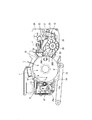
図1には、この発明によるレーザ複写機の要部の概略構成を示す。
【0031】
図中符号10は、像担持体であるドラム状の感光体である。図1から判るとおり、感光体10のまわりには、その上に設ける帯電装置11から感光体10の矢印Aで示す回転方向に順に、右に現像装置12、下に転写・搬送装置13、左にクリーニング装置15を設ける。
【0032】
そして、コピーを取るときは、公知のとおり、不図示のコンタクトガラス上に原稿をセットしてから、コピースイッチを押し、図示しない画像読取装置で原稿の画像を読み取ると同時に、感光体10と転写・搬送装置13間に用紙などのシートを送り込む。
【0033】
一方、感光体10は、所定の周速度で回転し、その回転にともない、帯電位置aで、表面を一様に帯電し、不図示の光書込み装置からレーザ光Lを照射して、書込位置bで表面に書き込みを行って、感光体10上に、上記読み取った原稿画像の静電潜像を形成し、続いて現像位置cで、現像剤を付着して、静電潜像を可視像化したトナー画像を形成する。そして、形成したトナー画像を、上述したとおり感光体10と転写・搬送装置13間の転写位置dで、搬送したシート上に転写する。
【0034】
転写後、シートは、静電的に付着する感光体10から、分離爪14により、機械的に分離して後、不図示の定着装置へ搬送してそこで転写画像を定着し、不図示の排紙部へと排出する。なお、分離爪14に代えて、放電装置を設け、感光体から静電的に分離するようにしてもよい。
【0035】
他方、画像転写後の感光体10は、表面に残った残留トナーをクリーニング位置eで、クリーニング装置15に備えるファーブラシ16とクリーニングブレード17で除去して表面をクリーニングして後、除電ランプ18で除電して表面電位を初期化する。
【0036】
なお、このような複写機において、例えば感光体10と帯電装置11と現像装置12とクリーニング装置15とを不図示のカートリッジケース内に備え、プロセスカートリッジを構成してもよい。そして、そのプロセスカートリッジを、複写機装置本体に対して例えば正面側から出し入れして一括して着脱自在とするとよい。
【0037】
さて、上述した感光体10の近傍には、図示省略するサーミスタを設ける。そして、サーミスタにより、感光体10の表面温度を測定する。なお、サーミスタに代えて、赤外線センサなどを設けて感光体10の表面温度を測定しても良い。
【0038】
また、上述した現像装置12は、上部側に現像剤収容部21を設け、下部側に現像剤担持部22を設けて構成する。
【0039】
現像剤収容部21には、キャリアとトナーとよりなる乾式二成分現像剤が、トナー補給部24から補給口25を介して補給され、その現像剤を収容する。また、現像剤収容部21には、現像剤を撹拌しながら現像剤担持部22へ搬送する搬送スクリュー23を設ける。
【0040】
一方、現像剤担持部22には、現像アジテータ28、撹拌ローラ29、例えば2つの現像剤担持体30A・30Bなどを設ける。
【0041】
現像アジテータ28は、搬送スクリュー23から搬送された現像剤を、撹拌しつつ、撹拌ローラ29へ搬送する。
【0042】
撹拌ローラ29は、現像アジテータ28から搬送された現像剤を、撹拌しつつ、現像剤担持体30A・30Bへ搬送する。
【0043】
現像剤担持体30A・30Bは、それぞれ内部に磁石を有し、ローラ状をしている。上に設ける現像剤担持体30Aは、現像剤供給量規制部材31によって、現像剤担持体30Aで担持する現像剤を薄層化して、感光体10へ現像剤を供給する。一方、下に設ける現像剤担持体30Bは、上に設ける現像剤担持体30Aによって、現像剤担持体30Bで担持する現像剤を薄層化して、感光体10へ現像剤を供給する。
【0044】
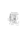
また、クリーニング装置15には、詳しくは図2に示すように、クリーニングケース部15aに、感光体10と対向して開口15bを設ける。その開口15bの感光体回転方向上流側にはファーブラシ16を、感光体回転方向下流側には、クリーニングブレード17を設ける。そして、ファーブラシ16とクリーニングブレード17で、感光体10上の残留トナーを除去して、画像転写後の感光体10をクリーニングする。
【0045】
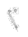
そのクリーニングブレード17は、図2および図3に示すように、細長な矩形状をし、ゴム製で、上端をブレードホルダ34に接着して設ける。そのブレードホルダ34は、細長で、断面L字状に設け、ブラケット35にねじ止めする。
【0046】
そのブラケット35には、細長で、断面略L字状の本体部35aを設ける。その本体部35aの両端にはそれぞれ、本体部35aの長さ方向に対して垂直に、略矩形状の支持部35bを設ける。
【0047】
それらの支持部35bの先端には、それぞれ軸部35cを突き立てて、それらの軸部35cを外向きに設ける。それらの軸部35cは、複写機本体が備える側板Fに設けた不図示の孔にそれぞれ通して、クリーニングブレード17を軸部35c中心に、図中矢印の方向に回動自在とする。
【0048】
また、図3中左側に示す軸部35cの先端にはカバー36を設けるとともに、軸部35cのまわりにはバネGを巻き付けて、クリーニングブレード17およびブラケット35などを、図中右側に付勢する。
【0049】
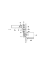
一方、図3中右側に示す軸部35cの先端には、図4に示すように、切欠Hを設ける。そして、切欠H内にピン37を入れ、そのピン37をネジ38で軸部35cの先端に取り付ける。そして、ブラケット35は、バネGにより図中右側に付勢するので、軸部35cの先端のピン37を、揺動ギヤ39の一方の側面に突き当てている。
【0050】
その揺動ギヤ39の一方の側面は、らせん状に設けて、カム面39aとする。そのカム面39aは、図5に示すように、段部39bを始点とし、図中反時計まわりに揺動ギヤ39を回転すると、その回転にともない高さが徐々に低くなる傾斜面とする。そのような揺動ギヤ39は、図4に示すように、固定ブラケット40の軸40aで回転自在に支持する。
【0051】
その揺動ギヤ39の下には、揺動ギヤ39に噛み合わせる駆動ギヤ41を、モータ42の駆動軸42aの先端に設ける。モータ42は、モータブラケット42bで固定ブラケット40に取り付けて支持する。固定ブラケット40には軸受43を設けて、駆動軸42aを回転自在とする。
【0052】
ところで、図2および図3に示すように、本体部35aのほぼ中央には、舌片Jを設け、その舌片Jには、バネ44の一端を取り付ける。一方、バネ44の他端は、複写機本体内の固定ブラケット45に取り付けて、クリーニングブレード17を感光体10に所定の圧力で押し当てる。
【0053】
また、クリーニング装置15には、クリーニングケース部15a内に、ファーブラシ16とクリーニングブレード17とで除去した残留トナーを、感光体10の幅方向に搬送するコイル状のトナー搬送部材32を備える。
【0054】
さらに、この複写機には、クリーニング装置15で回収した残留トナーを、パイプ等で形成した搬送通路を通して、スクリュ・コイル・ベルト等の搬送部材を用いたり重力を利用したりして現像装置12の現像剤収容部21へと戻す不図示のトナーリサイクル装置を備える。
【0055】
そして、コピー時、図1に示す現像装置12では、不図示の駆動モータを駆動し、その駆動を伝達して、搬送スクリュー23、現像アジテータ28、撹拌ローラ29、現像剤担持体30A・30Bをそれぞれ回転する。
【0056】
それにより、現像剤収容部21内に収納する現像剤を撹拌し、トナーとキャリアを摩擦帯電しながら、現像剤担持部22へと搬送する。その後、現像剤担持部22内の現像剤を、同様に撹拌しながら、現像アジテータ28、撹拌ローラ29を介して、現像剤担持体30A・30Bへ搬送する。
【0057】
一方、現像剤担持体30A・30Bには、所定バイアスを印加して、現像剤担持体30A・30B上に現像剤を付着する。そして、現像剤担持体30A・30Bの回転とともに、それらで担持する現像剤をそれぞれ薄層化してから、その薄層化後の現像剤中のトナーを、感光体10上に形成した静電潜像に静電的に付着し、感光体10上に可視像化したトナー画像を形成する。
【0058】
また、クリーニング装置15では、感光体10の矢印Aで示す時計まわりの回転とともに、ファーブラシ16を反時計まわりに回転し、ファーブラシ16とクリーニングブレード17とで、残留トナーを除去する。このとき、ファーブラシ16は、感光体10と接触する位置で、同方向に回転するので、クリーニングケース部15a内から残留トナーが漏れることを防止しつつ、残留トナーを、保持部15c内に溜める。
【0059】
その保持部15c内の残留トナーは、トナー搬送部材32の時計まわりの回転駆動によりただちに搬送して、クリーニングケース部15a内の手前側に集め、トナーリサイクル装置で現像装置12に戻す。
【0060】
また、例えば感光体10の回転とともに、図4に示すモータ42を駆動し、駆動軸42aを介して、図3に示す駆動ギヤ41を時計まわりに回転する。その回転により、カム面39aを備える揺動ギヤ39が、図中矢印で示す反時計まわりに回転する。それにより、バネGの弾性力に抗して、ブラケット35を図中左側に移動する。やがて、ピン37が、カム面39aの段部39bで落下すると、バネGの弾性力によりブラケット35が図中右側にただちに移動する。そして、揺動ギヤ39の回転の繰り返しによって、クリーニングブレード17を感光体10の幅方向に揺動する。
【0061】
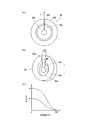
なお、揺動ギヤ39に代えて、例えば図6で示す揺動ギヤ50としても良い。その揺動ギヤ50の一方の側面は、らせん状のカム面を2つ有する。図6に示すように、内側のカム面50aと外側のカム面50bは、それぞれの段部50c、50dを始点とし、図中反時計まわりに揺動ギヤ50を回転すると、その回転にともない高さがそれぞれ徐々に低くなる傾斜面とする。
【0062】
また、段部50cにおける高さをH1とし、段部50dにおける高さをH2とすると、H1<H2の関係とする。
【0063】
このような揺動ギヤ50を用い、その揺動ギヤ50を図6(B)中矢印で示す上下方向に移動して、図4に示すブラケット35の先端に取り付けたピン37を、図6に示すカム面50aまたはカム面50bに当たるようにしても良い。このようにすれば、ピン37が当たるカム面50a・50bによって、クリーニングブレード17の揺動幅を、H1またはH2の2通りに異なるようにすることができる。
【0064】
なお、上述した例では、揺動幅が2通りに異なるものを説明したが、この発明はそれに限られず、揺動幅が3通り以上異なるようにしても良い。
【0065】
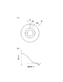
次に、当初から一定の揺動幅でクリーニングブレード17を揺動する複写機(感光体10の幅方向に2mm揺動するもの)と、揺動幅を時間の経過とともに増加する複写機(画像形成枚数が5K枚まで揺動せず、それ以降、感光体10の幅方向に2mm揺動するもの)とをそれぞれ用意し、一定枚数の画像を形成し、そのときのそれぞれのクリーニングブレード17の偏摩耗量を測定した。
【0066】
また、それらの複写機には、トナー中にワックスを添加しない現像剤をそれぞれに用い、それらの複写機が備える感光体の直径は30mmである。その結果を図7に示す。
【0067】
通常、クリーニングブレード17の偏摩耗量が10μm以上となったとき、クリーニング不良が発生しやすくなり、画像形成不良が発生するようになる。そこで、この実験では、偏摩耗量が10μmとなったときを、クリーニングブレード17の許容限界とした。また、一定枚数の画像を形成したとき、として60K枚画像を形成したときを主に比較した。
【0068】
クリーニングブレード17を当初から一定の揺動幅で揺動するものは、およそ40K枚画像形成したとき、クリーニングブレード17の偏摩耗量が10μmを越えた。
【0069】
一方、時間の経過とともにクリーニングブレード17の揺動幅を増加するものは、およそ60K枚画像形成したとき、クリーニングブレード17の偏摩耗量が10μmを越えた。
【0070】
したがって、クリーニングブレード17の揺動幅を、時間の経過とともに増加すれば、クリーニングブレード17のエッジが早期に劣化することを防止し、クリーニング性能を長期間維持して、画像品質の低下を防止することができる。また、クリーニングブレード17のエッジが早期に劣化することを防止できるので、感光体10の表面が早期に劣化することを防止して、画像品質の低下を防止することができる。
【0071】
なお、上述した例では、画像形成枚数が5K枚まで揺動せず、それ以降、感光体10の幅方向に2mm揺動したものを、揺動幅を時間の経過とともに増加するものとして説明したが、この発明はそれに限られず、画像形成装置の使用のはじめから、小さい幅で揺動し、所定の期間経過後、大きい幅で揺動しても良い。
【0072】
ところで、上述した例では、トナー中にワックスを添加しない現像剤を用いて実験を行ったが、次に、トナー中にワックスを添加した現像剤を用いて、同様の実験を行った。その結果を図8に示す。
【0073】
当初から揺動幅が一定のものは、およそ50K枚画像形成した後、クリーニングブレード17の偏摩耗量が10μmを越えた。
【0074】
一方、揺動幅が経時的に増加するものは、およそ60K枚画像形成したとき、クリーニングブレード17の偏摩耗量が6μmであった。
【0075】
したがって、トナー中にワックスを添加した現像剤を用いる画像形成装置において、クリーニングブレード17の揺動幅を、時間の経過とともに増加すれば、クリーニングブレード17のエッジが早期に劣化することを防止し、クリーニング性能を長期間維持して、画像品質の低下を防止することができる。また、クリーニングブレード17のエッジが早期に劣化することを防止できるので、感光体10の表面が早期に劣化することを防止して、画像品質の低下を防止することができる。
【0076】
ところで、感光体10の表面温度は、通常、20℃〜35℃くらいである。しかし、連続して画像を形成すると、定着を行う際の熱によって、複写機本体内の温度が上昇し、感光体10の表面温度も上昇する。また、シートの両面に画像を形成すると、表面に定着をおこなったシートを、感光体10と転写・搬送装置13間に送り込むことにより、感光体10に熱が持ち込まれ、感光体10の表面温度が上昇する。よって、複写機の機外温度、すなわち環境温度が高い場合、連続して画像を形成した場合、またはシートの両面に画像を形成した場合には、感光体10の表面温度が上昇する。
【0077】
一方、環境温度が低い場合、または画像を形成する頻度が少ない場合、感光体10の表面温度が低下する。
【0078】
そこで、トナー中にワックスを添加した現像剤を用いる複写機において、感光体10の表面温度が高い場合と低い場合に、クリーニングブレード17の偏摩耗量がそれぞれどのように変化するのか実験した。
【0079】
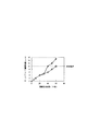
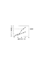
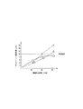
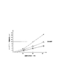
その実験結果を図9および図10に示す。実験では、当初から一定の揺動幅でクリーニングブレード17を揺動した複写機(感光体10の幅方向に2mm揺動したもの(揺動幅一定のものを×で示す))、揺動幅を時間の経過とともに増加した複写機(画像形成枚数が5K枚まで揺動せず、それ以降、感光体10の幅方向にクリーニングブレード17を1mm揺動したものを☆で、2mm揺動したものを△で、4mmで揺動したものを○でそれぞれ示す)とをそれぞれ用意し、一定枚数の画像を形成し、その時のそれぞれのクリーニングブレード17の偏摩耗量を測定した。
【0080】
なお、図9で結果を示す複写機は、環境温度が10℃、相対湿度が15%で実験を行い、一方、図10で結果を示す複写機は、環境温度が30℃、相対湿度が90%で実験を行った。すなわち、図9で示すものは、感光体10の表面温度を低くする一方、図10で示すものは、感光体10の表面温度を高くして実験を行った。
【0081】
図9に示すもので、当初から一定の揺動幅のもの(図9中×で示すもの)は、およそ40K枚で偏摩耗量が10μmを越え、画像形成枚数が5K枚まで揺動せず、それ以降、感光体10の幅方向にクリーニングブレード17を2mm揺動したもの(図9中△で示すもの)は、およそ60K枚で偏摩耗量が10μmを越え、画像形成枚数が5K枚まで揺動せず、それ以降感光体10の幅方向にクリーニングブレード17を4mm揺動したもの(図9中○で示すもの)は、60K枚画像を形成したとき偏摩耗量がおよそ9μmであった。
【0082】
図9の実験結果から、感光体10の温度が低い場合、揺動幅を大きくしてもクリーニングブレード17の劣化がさほど大きくないことが判る。
【0083】
また、図10に示すもので、当初から揺動幅一定のもの(図10中×で示すもの)は、およそ40K枚で偏摩耗量が10μmを越え、画像形成枚数が5K枚まで揺動せず、それ以降感光体10の幅方向にクリーニングブレード17を2mm揺動したもの(図10中△で示すもの)は、およそ60K枚で偏摩耗量が10μmを越え、画像形成枚数が5K枚まで揺動せず、それ以降感光体10の幅方向にクリーニングブレード17を1mm揺動したもの(図10中☆で示すもの)は、60K枚画像を形成したとき偏摩耗量が6μmであった。
【0084】
図10から、感光体10の温度が高い場合、揺動幅を大きくすると、クリーニングブレード17の劣化が大きくなることが判る。
【0085】
そこで、感光体10の温度が低い場合、揺動幅を広くしてクリーニング性能を向上するようにし、一方温度が高い場合、揺動幅を狭くして、クリーニングブレード17のエッジや感光体10の表面の劣化を防止するようにし、感光体10の温度に応じて、クリーニングブレード17の揺動幅を異なるようにすれば、クリーニングブレード17のエッジや感光体10の表面が早期に劣化することを防止しながら、クリーニング性能を長期間維持して、画像品質の低下を防止することができる。
【0086】
なお、上述した例では、狭い揺動幅が1mm、通常の揺動幅が2mm、広い揺動幅が4mmのもので説明したが、この発明は、それに限られず、適宜の幅で、感光体10の温度に応じて、揺動幅を異なるようにしても良い。
【0087】
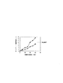
次いで、30mm、40mm、50mm、60mmの直径の感光体10を備える複写機をそれぞれ用意し、一定枚数の画像を形成した後、それぞれの複写機が備えるクリーニングブレード17の偏摩耗量を測定した。
【0088】
このとき、一定の揺動幅でクリーニングブレード17を揺動し(感光体10の幅方向に2mm揺動)、ワックスを添加しないトナーをそれぞれ用いた。そして、30mmまたは60mmの直径の感光体10を備える複写機の結果を図11に示す。
【0089】
30mmのものは、およそ40K枚画像形成した後、クリーニングブレード17の偏摩耗量が10μmを越えた。
【0090】
一方、60mmのものは、60K枚画像形成した後、クリーニングブレード17の偏摩耗量は、およそ8μmであった。
【0091】
したがって、直径が小さい感光体10を用いると、それだけクリーニングブレード17の偏摩耗量が大きくなることが分かる。
【0092】
また、この実験により、特に、感光体10の直径が、40mm以下のものは、クリーニングブレード17のエッジや感光体10の表面が早期に劣化し、クリーニング性能を長期間維持できず、画像品質を低下することが判った。
【0093】
そこで、感光体10の直径が40mm以下の複写機において、クリーニングブレード17の揺動幅を、時間の経過とともに増加すれば、クリーニングブレード17のエッジや感光体10の表面が早期に劣化することを防止しながら、クリーニング性能を長期間維持して、画像品質の低下を防止することができる。
【0094】
ところで、複写機において、トナー中のワックス添加量を3.5重量%より小とすると、定着の際にオフセットが発生する。一方、トナー中のワックス添加量を5.0重量%より大とすると、トナー帯電量が低下する一方、クリーニングブレード17のエッジや感光体10の表面に偏摩耗が発生して、画像品質が低下する。
【0095】
そこで、トナー中のワックス添加量を、3.5〜5.0重量%とすれば、定着の際に発生するオフセットを防止することができる。加えて、トナー帯電量の低下を防止するとともに、クリーニングブレード17のエッジや感光体10の表面に偏摩耗が発生することを防止して、画像品質の低下を防止することができる。
【0096】
また、2成分現像剤のトナーの中には、低温で定着可能なものがある。そのトナーは、平均粒径10μm以下であり、少なくとも結着樹脂および着色剤を含有し、テトラヒドロフラン(THF)可溶分により求められたゲルパミエーションクロマトグラフィー(GPC)による分子量分布の値が1,000〜10,000の間に少なくとも1つのピークを有し、分子量分布の半値幅が15,000以下であった。そして、このトナーは、わずかな熱や圧力が加えられた場合でもワックスが染み出た。
【0097】
そして、このようないわゆる低温定着トナーとキャリアとを有する2成分現像剤を使用する複写機において、感光体10上の残留トナーの堆積量に偏差があった場合、トナーから染み出たワックスにより摩擦力の偏差が大きくなってしまい、クリーニングブレード17のエッジおよび感光体10の表面に偏摩耗が発生してしまう。
【0098】
そこで、2成分現像剤を使用する複写機において、前述した例のように、クリーニングブレード17の揺動幅を、時間の経過とともに増加したり、感光体10の温度に応じて揺動幅を異なるようにしたりすれば、クリーニングブレード17のエッジや感光体10の表面が早期に劣化することを防止しながら、クリーニング性能を長期間維持して、画像品質の低下を防止することができる。
【0099】
【発明の効果】
以上説明したとおり、請求項1に係る発明によれば、クリーニングブレードの揺動幅を、時間の経過とともに増加するので、画像形成装置を設置したときは、クリーニングブレードを揺動せず、または小さい揺動幅で揺動し、適宜の期間を経過し、トナーがブレードの長さ方向にほぼ均一に付着して後、大きい揺動幅で揺動するから、クリーニングブレードのエッジや像担持体の表面が早期に劣化することを防止しながら、クリーニングブレードを揺動して像担持体とクリーニングブレードとの間に挟み込んだ異物を除去してクリーニング性能を長期間維持し、画像品質の低下を防止することができる。
【0101】
請求項2に係る発明によれば、プロセスカートリッジが、請求項1に記載のクリーニング装置を備えるから、上述した各効果を有するクリーニング装置を備えるとともにメンテナンス性を向上したプロセスカートリッジを提供することができる。
【0102】
請求項3に係る発明によれば、画像形成装置が、請求項1に記載のクリーニング装置を備えるから、上述した効果を有するクリーニング装置を備える画像形成装置を提供することができる。
【0103】
請求項4に係る発明によれば、画像形成装置が、請求項2に記載のプロセスカートリッジを備えるから、上述した各効果を有するプロセスカートリッジを備える画像形成装置を提供することができる。
【0104】
請求項5に係る発明によれば、像担持体の直径が、40mm以下であるので、特にクリーニングブレードのエッジが早期に劣化したり、像担持体の表面に偏摩耗が発生したりしやすい、直径の小さい像担持体を用いる画像形成装置において、クリーニングブレードのエッジや像担持体の表面が早期に劣化することを防止しながら、クリーニング性能を長期間維持して、画像品質の低下を防止することができる。
【0105】
請求項6に係る発明によれば、ワックスを添加したトナーを使用し、そのトナー中のワックス添加量が、3.5〜5.0重量%であるので、定着の際に発生するオフセットを防止することができる。加えて、トナー帯電量の低下を防止する一方、像担持体の表面やクリーニングブレードに偏摩耗が発生することを防止することができるから、クリーニングブレードのエッジや像担持体の表面が早期に劣化することを防止しながら、クリーニング性能を長期間維持して、画像品質の低下を防止することができる。
【0106】
請求項7に係る発明によれば、いわゆる低温定着トナーとキャリアとを有する2成分現像剤を使用する画像形成装置であるので、クリーニングブレードのエッジや像担持体の表面が早期に劣化することを防止しながら、クリーニング性能を長期間維持して、画像品質の低下を防止することができる。
【図面の簡単な説明】
【図1】この発明によるレーザ複写機の要部の概略構成図である。
【図2】そのレーザ複写機が備えるクリーニング装置の概略構成図である。
【図3】そのクリーニング装置の要部の斜視図である。
【図4】そのクリーニング装置への駆動伝達系の構成図である。
【図5】そのクリーニング装置が備える揺動ギヤの、(A)は側面図、(B)は回転角度とカム面の高さとの関係を示す説明図である。
【図6】そのクリーニング装置が備える別の揺動ギヤの、(A)は側面図、(B)は斜視図、(C)は回転角度とカム面の高さとの関係を示す説明図である。
【図7】トナーにワックスを添加しない現像剤を用いる画像形成装置において、画像形成枚数とクリーニングブレードの偏摩耗量との関係を示す説明図である。
【図8】トナーにワックスを添加した現像剤を用いる画像形成装置において、画像形成枚数とクリーニングブレードの偏摩耗量との関係を示す説明図である。
【図9】感光体の温度が低い場合において、画像形成枚数とクリーニングブレードの偏摩耗量との関係を示す説明図である。
【図10】感光体の温度が高い場合において、画像形成枚数とクリーニングブレードの偏摩耗量との関係を示す説明図である。
【図11】感光体の直径を変えた場合において、画像形成枚数とクリーニングブレードの偏摩耗量との関係を示す説明図である。
【符号の説明】
10 感光体(像担持体)
15 クリーニング装置
17 クリーニングブレード[0001]
BACKGROUND OF THE INVENTION
The present invention relates to an image forming apparatus that forms an image on a sheet such as a sheet or an OHP film, such as a copying machine, a printer, a facsimile, or a complex machine thereof. The present invention also relates to a cleaning device that is provided in such an image forming apparatus and that cleans an image carrier after image transfer. The present invention also relates to a process cartridge that includes such a cleaning device and at least an image carrier and is detachable from the image forming apparatus in a lump.
[0002]
[Prior art]
Conventionally, in an electrophotographic image forming apparatus, for example, an electrostatic latent image is formed on an image carrier by charging and writing, and a toner is attached to the electrostatic latent image and developed to make a visible image, The toner image on the image carrier formed by the visualization is transferred to a sheet to form an image. Then, the paper after the image transfer is passed through a fixing device to fix the unfixed transfer image on the paper, while the image carrier after the image transfer is cleaned by a cleaning device.
[0003]
By the way, a cleaning device used in this type of image forming apparatus includes a cleaning blade, and the cleaning blade is pressed against a drum-shaped image carrier with a predetermined pressure to clean the image carrier after image transfer. was there.
[0004]
However, an image forming apparatus provided with such a cleaning device generates a cleaning defect due to a foreign matter sandwiched between the image carrier and the cleaning blade, and causes vertical streaks on the formed image. As a result, there is a problem that the image quality deteriorates.
[0005]
[Patent Document 1]
JP-A-10-186989
[Patent Document 2]
Japanese Patent Laid-Open No. 11-219088
In order to solve this problem, conventional image forming apparatuses have techniques described in, for example, Patent Document 1 and Patent Document 2. The cleaning apparatus described in these documents removes foreign matters by swinging the cleaning blade with a constant width in the width direction of the image carrier as the image carrier rotates during image formation, and the cleaning failure. Occurrence was prevented, and deterioration of image quality was prevented.
[0006]
[Problems to be solved by the invention]
However, when there is a deviation in the amount of residual toner deposited on the image carrier, such as when the image forming apparatus is used for the first time after installation or when a small size image is continuously formed, the cleaning blade A portion having a large frictional force and a portion having a small friction force are formed between the image carrier and the image carrier. If the cleaning blade is swung in a state where there is a deviation in the magnitude of the frictional force, the edge of the cleaning blade deteriorates at the part where the frictional force is large, and the cleaning performance is deteriorated early and the image quality is deteriorated. In addition, there is a problem that uneven wear occurs on the surface of the image carrier and the image quality deteriorates.
[0007]
Accordingly, a first object of the present invention is to maintain the cleaning performance for a long period of time while preventing the edge of the cleaning blade and the surface of the image carrier from deteriorating early, and to prevent the image quality from deteriorating. is there.
[0008]
Conventionally, there has been a toner in which wax is added to a toner used in an image forming apparatus, mainly for the purpose of preventing an offset generated during fixing.
[0009]
The amount of the wax oozing out from the toner is small when the temperature is low and large when it is high. Moreover, the larger the amount of the wax oozing out, the more reliably the occurrence of offset can be prevented.
[0010]
However, the amount of wax oozing out from the toner increases, and as in the case of the example described above, when there is a deviation in the amount of toner accumulated on the image carrier, the deviation in frictional force is further increased by the wax. End up. Therefore, there is a problem that the above-described problem is further deteriorated.
[0011]
Accordingly, a second object of the present invention is to provide an image forming apparatus using a toner to which wax is added, in particular, the edge of the cleaning blade is deteriorated at an early stage or uneven wear is likely to occur on the surface of the image carrier. In the cleaning device, the edge of the cleaning blade and the surface of the image carrier are prevented from prematurely deteriorating, and the cleaning performance is maintained for a long period of time to prevent the image quality from deteriorating.
[0012]
A third object of the present invention is to provide a process cartridge having a cleaning device that achieves the above-mentioned object and having improved maintainability.
[0013]
A fourth object of the present invention is to provide an image forming apparatus provided with a cleaning device that achieves the first or second object.
[0014]
A fifth object of the present invention is to provide an image forming apparatus provided with a process cartridge that achieves the third object.
[0015]
By the way, when the number of image formations per predetermined time is the same, if the diameter of the image carrier provided in the image forming apparatus is small, the number of rotations of the image carrier increases. Therefore, when an image carrier having a small diameter is used, the above-described uneven wear of the image carrier and the cleaning blade is increased accordingly.
[0016]
SUMMARY OF THE INVENTION Accordingly, a sixth object of the present invention is to provide an image forming apparatus using an image carrier having a small diameter in which the edge of the cleaning blade is deteriorated at an early stage or uneven wear is likely to occur on the surface of the image carrier. An object of the present invention is to maintain the cleaning performance for a long period of time while preventing the deterioration of the image quality while preventing the edge of the cleaning blade and the surface of the image carrier from prematurely deteriorating.
[0017]
Now, in an image forming apparatus using toner added with wax, there is a problem that if the amount of added wax is reduced, offset occurs during fixing. On the other hand, when the amount of added wax is increased, there is a problem that the toner charge amount is reduced, or uneven wear occurs on the edge of the cleaning blade or the surface of the image carrier, thereby deteriorating the image quality.
[0018]
Accordingly, a seventh object of the present invention is to prevent an offset that occurs during fixing in an image forming apparatus using toner to which wax is added, and to prevent a decrease in toner charge amount. An object of the present invention is to maintain the cleaning performance for a long period of time while preventing the surface of the carrier from prematurely deteriorating and to prevent the image quality from deteriorating.
[0019]
Conventionally, some toners can be fixed at a low temperature. The toner has an average particle size of 10 μm or less, contains at least a binder resin and a colorant, and has a molecular weight distribution value of 1, determined by gel permeation chromatography (GPC) obtained from tetrahydrofuran (THF) soluble matter. It had at least one peak between 000 and 10,000, and the half width of the molecular weight distribution was 15,000 or less. Even when slight heat or pressure was applied to the toner, the wax oozed out.
[0020]
However, as in the case of the above-described example, when there is a deviation in the amount of residual toner deposited on the image carrier, the deviation of the frictional force is further increased due to the wax that exudes from the toner. Therefore, there is a problem that the above-described problem is further deteriorated.
[0021]
Accordingly, an eighth object of the present invention is to provide an image forming apparatus using a so-called low-temperature fixing toner, in which the edge of the cleaning blade is deteriorated at an early stage or uneven wear is likely to occur on the surface of the image carrier. An object of the present invention is to maintain the cleaning performance for a long period while preventing the deterioration of the image quality while preventing the edge of the cleaning blade and the surface of the image carrier from being deteriorated early.
[0022]
[Means for Solving the Problems]
Therefore, the invention described in claim 1 is to achieve the first object described above.
In a cleaning device provided in an image forming apparatus, wherein a cleaning blade for cleaning an image carrier after image transfer is swung in the width direction of the image carrier.
The swinging width of the cleaning blade is increased with time.
[0024]
Claim2In order to achieve the third object described above, the invention described in
Claim1A process cartridge comprising the cleaning device described above.The
[0025]
Claim3In order to achieve the fourth object described above, the invention described in
Claim1It is an image forming apparatus provided with the cleaning apparatus of description.
[0026]
Claim4In order to achieve the fifth object described above, the invention described in
Claim2An image forming apparatus comprising the process cartridge described in 1 above.
[0027]
Claim5In order to achieve the sixth object described above, the invention described in
Claim3Or4In the image forming apparatus described in 1.
The diameter of the image carrier is 40 mm or less.
[0028]
Claim6In order to achieve the seventh object described above, the invention described in
Claim3Or5In the image forming apparatus according to any one of the above,
Use toner with added wax,The amount of wax added in the toner is 3.5 to 5.0% by weight.
[0029]
Claim7In order to achieve the above-mentioned eighth object,
Claim6In the image forming apparatus described in 1.
Gel permeation obtained by using a two-component developer having a toner and a carrier, the toner having an average particle size of 10 μm or less, containing at least a binder resin and a colorant, and being soluble in tetrahydrofuran (THF) The molecular weight distribution value by chromatography (GPC) has at least one peak between 1,000 and 10,000, and the half width of the molecular weight distribution is 15,000 or less.
[0030]
DETAILED DESCRIPTION OF THE INVENTION
Hereinafter, embodiments of the present invention will be described with reference to the drawings.
FIG. 1 shows a schematic configuration of a main part of a laser copying machine according to the present invention.
[0031]
[0032]
When making a copy, as is well known, a document is set on a contact glass (not shown), a copy switch is pressed, and an image of the document is read by an image reading device (not shown), and at the same time transferred to the
[0033]
On the other hand, the
[0034]
After the transfer, the sheet is mechanically separated from the electrostatically adhered
[0035]
On the other hand, after the image transfer, the
[0036]
In such a copying machine, for example, the
[0037]
A thermistor (not shown) is provided in the vicinity of the
[0038]
Further, the developing
[0039]
The
[0040]
On the other hand, the
[0041]
The
[0042]
The
[0043]
Each of the
[0044]
Further, in the
[0045]
As shown in FIGS. 2 and 3, the
[0046]
The
[0047]
The
[0048]
Further, a
[0049]
On the other hand, as shown in FIG. 4, a notch H is provided at the tip of the
[0050]
One side surface of the
[0051]
Below the
[0052]
By the way, as shown in FIGS. 2 and 3, a tongue piece J is provided substantially at the center of the
[0053]
Further, the
[0054]
Further, in this copying machine, the residual toner collected by the
[0055]
During copying, the developing
[0056]
As a result, the developer stored in the
[0057]
On the other hand, a predetermined bias is applied to the
[0058]
In the
[0059]
Residual toner in the holding
[0060]
Further, for example, with the rotation of the
[0061]
Instead of the
[0062]
Further, assuming that the height at the stepped
[0063]
Using such a
[0064]
In the above-described example, the two different swing widths have been described. However, the present invention is not limited to this, and the swing width may be three or more different.
[0065]
Next, a copying machine that swings the
[0066]
Further, in these copying machines, a developer that does not add wax to the toner is used for each, and the diameter of the photoreceptor provided in these copying machines is 30 mm. The result is shown in FIG.
[0067]
Normally, when the amount of uneven wear of the
[0068]
When the
[0069]
On the other hand, in the case of increasing the swinging width of the
[0070]
Therefore, if the swinging width of the
[0071]
In the above-described example, the case where the number of image formations does not swing up to 5K, and after that, the case where the
[0072]
By the way, in the above-described example, an experiment was performed using a developer to which no wax was added in the toner. Next, a similar experiment was performed using a developer to which wax was added in the toner. The result is shown in FIG.
[0073]
When the rocking width was constant from the beginning, the uneven wear amount of the
[0074]
On the other hand, when the swing width increased with time, the amount of uneven wear of the
[0075]
Therefore, in the image forming apparatus using the developer in which wax is added to the toner, if the swinging width of the
[0076]
By the way, the surface temperature of the
[0077]
On the other hand, when the environmental temperature is low, or when the frequency of image formation is low, the surface temperature of the
[0078]
Therefore, in a copying machine using a developer in which wax is added to the toner, an experiment was conducted to determine how the uneven wear amount of the
[0079]
The experimental results are shown in FIG. 9 and FIG. In the experiment, the copying machine (from which the
[0080]
The copying machine showing the results in FIG. 9 performs the experiment at an environmental temperature of 10 ° C. and a relative humidity of 15%, while the copying machine showing the results in FIG. 10 has an environmental temperature of 30 ° C. and a relative humidity of 90%. % Experiment was conducted. That is, in the example shown in FIG. 9, the surface temperature of the
[0081]
The one shown in FIG. 9 having a constant swing width (indicated by x in FIG. 9) is about 40K sheets, the amount of uneven wear exceeds 10 μm, and the number of image forming sheets does not swing up to 5K sheets. Thereafter, when the
[0082]
From the experimental results shown in FIG. 9, it can be seen that when the temperature of the
[0083]
Further, the one shown in FIG. 10 having a constant swing width (indicated by “X” in FIG. 10) from the beginning is about 40K sheets, the uneven wear amount exceeds 10 μm, and the number of image forming sheets is swung to 5K sheets. After that, when the
[0084]
From FIG. 10, it can be seen that when the temperature of the
[0085]
Therefore, when the temperature of the
[0086]
In the example described above, the narrow swing width is 1 mm, the normal swing width is 2 mm, and the wide swing width is 4 mm. However, the present invention is not limited to this, and the photosensitive member has an appropriate width. Depending on the temperature of 10, the swinging width may be different.
[0087]
Next, copiers each including the
[0088]
At this time, the
[0089]
In the case of 30 mm, the uneven wear amount of the
[0090]
On the other hand, in the case of 60 mm, after 60K images were formed, the amount of uneven wear of the
[0091]
Therefore, it can be seen that the uneven wear amount of the
[0092]
Further, according to this experiment, especially when the diameter of the
[0093]
Therefore, in the copying machine having the diameter of the
[0094]
By the way, in the copying machine, if the amount of wax added in the toner is less than 3.5% by weight, an offset occurs during fixing. On the other hand, if the amount of wax added to the toner is greater than 5.0% by weight, the toner charge amount is reduced, while uneven wear occurs on the edge of the
[0095]
Therefore, if the amount of wax added in the toner is 3.5 to 5.0% by weight, offset that occurs during fixing can be prevented. In addition, the toner charge amount can be prevented from being lowered, and uneven wear can be prevented from occurring on the edge of the
[0096]
Some toners of two-component developers can be fixed at a low temperature. The toner has an average particle size of 10 μm or less, contains at least a binder resin and a colorant, and has a molecular weight distribution value of 1, determined by gel permeation chromatography (GPC) obtained from tetrahydrofuran (THF) soluble matter. It had at least one peak between 000 and 10,000, and the half width of the molecular weight distribution was 15,000 or less. This toner exudes wax even when slight heat or pressure is applied.
[0097]
In a copying machine using such a two-component developer having a so-called low-temperature fixing toner and a carrier, if there is a deviation in the amount of residual toner deposited on the
[0098]
Therefore, in a copying machine using a two-component developer, the swinging width of the
[0099]
【The invention's effect】
As described above, according to the first aspect of the present invention, since the swinging width of the cleaning blade increases with time, the cleaning blade does not swing or is small when the image forming apparatus is installed. After a suitable period of time has passed, the toner adheres almost uniformly in the length direction of the blade, and then swings with a large swing width, so the edge of the cleaning blade and the image carrier While preventing the surface from prematurely deteriorating, the cleaning blade is swung to remove foreign matter caught between the image carrier and the cleaning blade, maintaining the cleaning performance for a long period of time and preventing the image quality from deteriorating. can do.
[0101]
Claim2According to the invention, the process cartridge is1Since the described cleaning device is provided, it is possible to provide a process cartridge having the cleaning device having the above-described effects and having improved maintainability.
[0102]
Claim3According to the invention, the image forming apparatus is1Since the above-described cleaning device is provided, an image forming apparatus including the cleaning device having the above-described effects can be provided.
[0103]
Claim4According to the invention, the image forming apparatus is2Therefore, it is possible to provide an image forming apparatus including the process cartridge having the above-described effects.
[0104]
Claim5According to the present invention, since the diameter of the image carrier is 40 mm or less, the edge of the cleaning blade is particularly deteriorated at an early stage, and uneven wear is likely to occur on the surface of the image carrier. In an image forming apparatus using an image carrier, the cleaning performance can be maintained for a long period of time while preventing the edge of the cleaning blade and the surface of the image carrier from prematurely deteriorating, thereby preventing deterioration in image quality. .
[0105]
Claim6According to the invention according toUse toner with added wax,Since the added amount of wax in the toner is 3.5 to 5.0% by weight, it is possible to prevent an offset that occurs during fixing. In addition, the toner charge amount can be prevented from decreasing, and the surface of the image carrier and the cleaning blade can be prevented from being unevenly worn, so that the edge of the cleaning blade and the surface of the image carrier are deteriorated early. While preventing this, it is possible to maintain the cleaning performance for a long period of time and prevent the image quality from deteriorating.
[0106]
Claim7According to the invention, since the image forming apparatus uses a two-component developer having a so-called low-temperature fixing toner and a carrier, the edge of the cleaning blade and the surface of the image carrier are prevented from prematurely deteriorating. In addition, the cleaning performance can be maintained for a long period of time, and the deterioration of the image quality can be prevented.
[Brief description of the drawings]
FIG. 1 is a schematic configuration diagram of a main part of a laser copying machine according to the present invention.
FIG. 2 is a schematic configuration diagram of a cleaning device provided in the laser copying machine.
FIG. 3 is a perspective view of a main part of the cleaning device.
FIG. 4 is a configuration diagram of a drive transmission system to the cleaning device.
5A is a side view of the swing gear provided in the cleaning device, and FIG. 5B is an explanatory view showing the relationship between the rotation angle and the height of the cam surface.
6A is a side view, FIG. 6B is a perspective view, and FIG. 6C is an explanatory diagram showing the relationship between the rotation angle and the cam surface height of another rocking gear provided in the cleaning device. .
FIG. 7 is an explanatory diagram showing the relationship between the number of images formed and the amount of uneven wear of a cleaning blade in an image forming apparatus using a developer that does not add wax to toner.
FIG. 8 is an explanatory diagram showing a relationship between the number of images formed and the amount of uneven wear of a cleaning blade in an image forming apparatus using a developer in which wax is added to toner.
FIG. 9 is an explanatory diagram showing the relationship between the number of images formed and the amount of uneven wear of the cleaning blade when the temperature of the photoconductor is low.
FIG. 10 is an explanatory diagram showing the relationship between the number of images formed and the amount of uneven wear of the cleaning blade when the temperature of the photosensitive member is high.
FIG. 11 is an explanatory diagram showing the relationship between the number of images formed and the amount of uneven wear of the cleaning blade when the diameter of the photoconductor is changed.
[Explanation of symbols]
10 Photoconductor (image carrier)
15 Cleaning device
17 Cleaning blade
Claims (7)
前記クリーニングブレードの揺動幅を、時間の経過とともに増加することを特徴とする、クリーニング装置。In a cleaning device provided in an image forming apparatus, wherein a cleaning blade for cleaning an image carrier after image transfer is swung in the width direction of the image carrier.
A cleaning device, wherein the swinging width of the cleaning blade increases with time.
Priority Applications (1)
| Application Number | Priority Date | Filing Date | Title |
|---|---|---|---|
| JP2003119928A JP4265750B2 (en) | 2003-04-24 | 2003-04-24 | Cleaning device, process cartridge, and image forming apparatus |
Applications Claiming Priority (1)
| Application Number | Priority Date | Filing Date | Title |
|---|---|---|---|
| JP2003119928A JP4265750B2 (en) | 2003-04-24 | 2003-04-24 | Cleaning device, process cartridge, and image forming apparatus |
Publications (2)
| Publication Number | Publication Date |
|---|---|
| JP2004325760A JP2004325760A (en) | 2004-11-18 |
| JP4265750B2 true JP4265750B2 (en) | 2009-05-20 |
Family
ID=33499010
Family Applications (1)
| Application Number | Title | Priority Date | Filing Date |
|---|---|---|---|
| JP2003119928A Expired - Fee Related JP4265750B2 (en) | 2003-04-24 | 2003-04-24 | Cleaning device, process cartridge, and image forming apparatus |
Country Status (1)
| Country | Link |
|---|---|
| JP (1) | JP4265750B2 (en) |
Families Citing this family (2)
| Publication number | Priority date | Publication date | Assignee | Title |
|---|---|---|---|---|
| JP6855717B2 (en) * | 2016-09-14 | 2021-04-07 | 富士ゼロックス株式会社 | Image forming device, color material control device, and color material control program |
| CN120535095B (en) * | 2025-06-04 | 2026-03-31 | 梅州联进化工有限公司 | A chemical production wastewater flocculation sedimentation tank treatment device |
-
2003
- 2003-04-24 JP JP2003119928A patent/JP4265750B2/en not_active Expired - Fee Related
Also Published As
| Publication number | Publication date |
|---|---|
| JP2004325760A (en) | 2004-11-18 |
Similar Documents
| Publication | Publication Date | Title |
|---|---|---|
| US8494386B2 (en) | Image forming apparatus featuring control of toner supply between image bearing member and cleaning blade | |
| JPH09218627A (en) | Collected toner transport device | |
| JP2004191737A (en) | Image forming apparatus | |
| JP4265750B2 (en) | Cleaning device, process cartridge, and image forming apparatus | |
| JP5174568B2 (en) | Developing device and image forming apparatus including the same | |
| JP7166811B2 (en) | image forming device | |
| JP4087134B2 (en) | Developing device and image forming apparatus | |
| JP2000066495A (en) | Developing device and image forming device using the same | |
| JP2001092256A (en) | Image forming unit and image forming apparatus | |
| JPH08314221A (en) | Image forming device | |
| JP7558687B2 (en) | Cartridge and image forming apparatus | |
| US20230305430A1 (en) | Developing device and image forming apparatus | |
| JP3365700B2 (en) | Image forming device | |
| JP2004212570A (en) | Image forming device | |
| JP2005234293A (en) | Developing roller, developing device, process unit, and image forming apparatus | |
| JP2002169443A (en) | Image forming device | |
| JP2003208068A (en) | Image carrier cleaning device and image forming apparatus provided with the device | |
| JP2000227743A (en) | Image forming device | |
| JPH04271381A (en) | Image forming device | |
| JP2025159662A (en) | Image forming device | |
| JP2003307985A (en) | Cleaning device and image forming apparatus provided with the same | |
| JP2026046739A (en) | Cleaning apparatus and image forming apparatus | |
| JP2025132886A (en) | Image forming device | |
| JPH08202127A (en) | Development device | |
| JPS5940679A (en) | Cleaning device of electrostatic copying machine |
Legal Events
| Date | Code | Title | Description |
|---|---|---|---|
| A621 | Written request for application examination |
Free format text: JAPANESE INTERMEDIATE CODE: A621 Effective date: 20050707 |
|
| A977 | Report on retrieval |
Free format text: JAPANESE INTERMEDIATE CODE: A971007 Effective date: 20080104 |
|
| A131 | Notification of reasons for refusal |
Free format text: JAPANESE INTERMEDIATE CODE: A131 Effective date: 20081017 |
|
| A521 | Written amendment |
Free format text: JAPANESE INTERMEDIATE CODE: A523 Effective date: 20081110 |
|
| TRDD | Decision of grant or rejection written | ||
| A01 | Written decision to grant a patent or to grant a registration (utility model) |
Free format text: JAPANESE INTERMEDIATE CODE: A01 Effective date: 20090210 |
|
| A01 | Written decision to grant a patent or to grant a registration (utility model) |
Free format text: JAPANESE INTERMEDIATE CODE: A01 |
|
| A61 | First payment of annual fees (during grant procedure) |
Free format text: JAPANESE INTERMEDIATE CODE: A61 Effective date: 20090210 |
|
| FPAY | Renewal fee payment (event date is renewal date of database) |
Free format text: PAYMENT UNTIL: 20120227 Year of fee payment: 3 |
|
| FPAY | Renewal fee payment (event date is renewal date of database) |
Free format text: PAYMENT UNTIL: 20130227 Year of fee payment: 4 |
|
| FPAY | Renewal fee payment (event date is renewal date of database) |
Free format text: PAYMENT UNTIL: 20130227 Year of fee payment: 4 |
|
| FPAY | Renewal fee payment (event date is renewal date of database) |
Free format text: PAYMENT UNTIL: 20140227 Year of fee payment: 5 |
|
| LAPS | Cancellation because of no payment of annual fees |