JP4262640B2 - Construction method of the impervious wall - Google Patents
Construction method of the impervious wall Download PDFInfo
- Publication number
- JP4262640B2 JP4262640B2 JP2004183176A JP2004183176A JP4262640B2 JP 4262640 B2 JP4262640 B2 JP 4262640B2 JP 2004183176 A JP2004183176 A JP 2004183176A JP 2004183176 A JP2004183176 A JP 2004183176A JP 4262640 B2 JP4262640 B2 JP 4262640B2
- Authority
- JP
- Japan
- Prior art keywords
- water
- soil cement
- panel
- joint
- impervious
- Prior art date
- Legal status (The legal status is an assumption and is not a legal conclusion. Google has not performed a legal analysis and makes no representation as to the accuracy of the status listed.)
- Expired - Fee Related
Links
Images


Description
本発明は、遮水パネルを有するソイルセメント地中連続壁を構築するための方法に関し、特に、雌雄の継手を有する幅が広くて薄肉の遮水パネルを打設用フレームと共にソイルセメント地中連続壁中に沈設する遮水地中壁の構築方法に関するものである。 TECHNICAL FIELD The present invention relates to a method for constructing a soil cement underground continuous wall having a water shielding panel, and in particular, a soil cement ground continuous with a wide and thin water shielding panel having a male and female joint together with a casting frame. The present invention relates to a method for constructing a water-impervious ground wall to be submerged in the wall.
地震その他の自然現象によりソイルセメント地中連続壁にクラックなどが発生して止水性が失われた場合でも止水できるように、ソイルセメント連続壁中に板状やシート状の止水部材を挿入することが知られていた(例えば、特許文献1参照)。
ソイルセメント地中壁中に合成樹脂製のシートを貫入フレームと共に沈設させ、貫入フレームを引き上げることにより合成樹脂製のシートを有するソイルセメント地中連続壁とすることも知られていた(例えば、特許文献2参照)。
又、空掘りした溝中に板状やシート状の止水材料を挿入した後に、若しくは溝を掘ることなく直接地中に、合成樹脂製のシートを貫入フレームと共に沈設させることも知られていた(例えば、特許文献3参照)。
一方、互いの雌継手と雄継手を密に係合し得る形状とすることにより、継手部においても止水状態とすることが知られていた(例えば、特許文献4参照)。
It has also been known that a synthetic resin sheet is placed in the soil cement underground wall together with the penetrating frame, and the penetrating frame is pulled up to form a soil cement underground continuous wall having a synthetic resin sheet (for example, patents). Reference 2).
It has also been known that a sheet made of synthetic resin is placed together with a penetrating frame after inserting a plate-like or sheet-like water-stopping material into an empty groove or directly in the ground without digging a groove. (For example, refer to Patent Document 3).
On the other hand, it has been known that the joint portion can be in a water-stopped state by making the female joint and the male joint into a shape that can be closely engaged with each other (see, for example, Patent Document 4).
しかしながら、上記の特許文献1においては、使用される止水部材は、貫入フレームを使用することなくソイルセメント壁中に沈設され、その剛性が高く、かつ図面に示されるように幅が狭いものであり、継手同士は密に接合され、連続壁中に継手による連結部を多数有するものである。
また、上記特許文献2においては、貫入フレームが使用されているものの、使用される止水部材は、その図3や図4に示されて文中に説明があるように、有孔幅Wが約1〜1.5mと幅狭のものであり、互いの雌継手と雄継手を密に係合し得る形状のものである。
特許文献3において使用される止水部材は、その文中の記載より、特許文献4に記載されたもの、即ち、互いの雌継手と雄継手を密に係合し得る形状のものであり、特許文献2と同様に、幅狭のものであり、互いの雌継手と雄継手を密に係合し得る形状のものである。
However, in the above-mentioned Patent Document 1, the water-stopping member used is set in the soil cement wall without using the penetration frame, has high rigidity, and has a narrow width as shown in the drawings. Yes, the joints are closely joined together and have a large number of joints in the continuous wall.
Moreover, in the said
The water-stop member used in
継手間隔が短いと、継手間隔の長い止水部材に比べると、継手を除く部材部よりも継手部の加工賃が高価となり、それ故、高価な止水材となるばかりでなく、一定長さの連続壁状とするには、継手間隔が短いと、継手間隔の長い止水部材に比べると多数の止水材が必要になる。このため一定長さの連続壁状にする際に多数回の沈設作業が必要となり、施工に要する手間と時間が必要になる。
また、互いの雌継手と雄継手を密に係合し得る形状のものであると、継手同士を接合する際に、互いに正確に位置決めする必要があるばかりでなく、互いに密接した状態で嵌合して次の止水材を沈設させるために、自沈させることは不可能であり、圧入貫入方式や高周波振動機による貫入方式を採らざるを得ない。
When the joint interval is short, the processing cost of the joint part is higher than that of the water-stopping member with a long joint interval, and therefore, it is not only an expensive water-stopping material but also a fixed length. In order to obtain a continuous wall shape, if the joint interval is short, a larger number of water-stopping materials are required than a water-stop member having a long joint interval. For this reason, many times of setting work are required to form a continuous wall having a certain length, and labor and time required for construction are required.
In addition, when the joints are shaped so that the female and male joints can be intimately engaged, not only do they need to be positioned accurately when they are joined, but they are also fitted in close contact with each other. Then, in order to set the next water-stopping material, it is impossible to make it self-sink, and it is necessary to adopt a press-fitting penetration method or a penetration method using a high-frequency vibrator.
本発明は、このような点に鑑み、雌継手と雄継手とは密に係合せずに互いに係合し得る構造を有し、かつ継手間隔の長い止水部材を使用することにより、これら従来技術の欠点を解決すると共に、このような止水部材を使用しても、継手部の止水性を確保しながら、止水部の挿入作業時にソイルセメント部に欠陥が生じることがないソイルセメント遮水地中壁を構築するための方法を提供することを目的とするものである。 In view of such a point, the present invention has a structure in which the female joint and the male joint can be engaged with each other without closely engaging them, and by using a water stop member having a long joint interval, In addition to solving the technical shortcomings, even if such a water-stopping member is used, the soil-cement barrier that does not cause defects in the soil-cement part during insertion of the water-stopping part while ensuring water-stopping of the joint part. The object is to provide a method for constructing an underwater wall.
本発明のソイルセメント遮水地中壁の構築方法は、ソイルセメントの地中連続壁を構築後、ソイルセメントが未硬化で流動性を有する間に、雌雄の継手を有する幅が広くて薄肉の遮水パネルを打設用フレームと共にソイルセメント中へ挿入し、地中連続壁中で前記遮水パネルの両面側にソイルセメント壁が存在する遮水地中壁を構築する方法であって、打設用フレームは、遮水パネルの継手部を除く部分よりも幅狭であって、肉厚の鋼製のものであり、その下方に遮水パネルを支える手段を備え、その上方に遮水パネルを保持開放自在な手段を備えると共に、該打設用フレームの遮水パネルを支える面の反対側にはグラウト注入路が装備されたものであり、前記遮水パネルが幅1.8〜2.5mの広幅薄肉鋼製パネルであり、片方に雌継手、他方に雄継手を有し、雌継手は最下端が封鎖されたものであり、かつ雌継手と雄継手とは密に係合せずに互いに係合し得る構造のものであり、上記遮水パネルの雌継手の側面に設けられた側面開口部(スリット部)を、ソイルセメントに挿入される前に、雄継手の上方からの挿入により破断される強度の材料で封鎖し、前記遮水パネルを打設用フレームに装着した状態でソイルセメント中に自沈させつつ、または自沈した後に、雌継手内に充填材を充填し、この雌継手に係合する雄継手を有する次の遮水パネルを打設用フレームに装着した状態でソイルセメント中に自沈させつつ、または自沈した後に、次の遮水パネルの雌継手内に充填材を充填するという工程を繰り返し、その後に打設用フレームを、そのグラウト注入路からグラウトを注入しながら地上に引き上げることを特徴とする遮水地中壁の構築方法である。 The method for constructing the soil cement water-impervious underground wall of the present invention is a method of constructing a soil cement underground continuous wall, and then, while the soil cement is uncured and has fluidity, has a wide and thin joint having male and female joints. A method of constructing a water-impervious underground wall in which a soil-cement wall exists on both sides of the water-impervious panel in a continuous underground wall by inserting the water-impervious panel into a soil cement together with a casting frame. The installation frame is narrower than the portion excluding the joint portion of the water-impervious panel and is made of thick steel, and is provided with means for supporting the water-impervious panel below the water-impervious panel. And a grouting channel on the opposite side of the surface for supporting the water shielding panel of the placing frame, and the water shielding panel has a width of 1.8-2. 5m of the wide is a thin-walled steel panel, the female joint on one side, A male joint on the side, the lower end of the female joint is sealed, and the female joint and the male joint can be engaged with each other without closely engaging, The side opening (slit part) provided on the side surface of the female joint is sealed with a material having a strength that can be broken by insertion from above the male joint before being inserted into the soil cement, and the water shielding panel is While self-sinking in the soil cement in the state where it is mounted on the casting frame, or after self-sinking , the female joint is filled with a filler, and the next water-impervious panel having a male joint engaged with the female joint is driven. The process of filling the filling into the female joint of the next water-impervious panel while self-sinking in the soil cement while it is attached to the installation frame, or after self-sinking , is followed by the installation frame Grouting from the grout injection channel A method for constructing a water shield underground wall, characterized in that pulling on the ground while.
この構築方法によると、遮水パネルの下端部は、打設用フレームの支え手段に保持されて、遮水パネルの上端が打設用フレームの上方の保持開放自在な手段で保持された状態で、ソイルセメントが未硬化で流動性を有する間に、打設用フレームと共にソイルセメント中へ自重で沈設させる(即ち、自沈させる)ことも可能になる。
特にソイルセメント壁に沿ってその両側に定規受け部材を設置し、この定規受け部材に、ソイルセメント壁の厚さ中心方向に張り出した部材の先端にローラを有し、定規受け部材に沿って移動可能で、かつ任意位置で固定可能な挿入定規部材を取付け、遮水パネルを装着した打設用フレームは、上端の吊りフックにより吊り下げた状態で該挿入定規部材のローラで位置規制してガイドさせつつ所定位置のソイルセメント中にその自重で自沈させる遮水地中壁の構築方法を採用すると、遮水パネルを装着した打設用フレームをソイルセメント中に自沈させる施工でも、所定位置に正確に沈設させることができるので好ましい構築方法である。
なお、遮水パネルの雌継手における側面開口部(スリット部)を、ソイルセメントに挿入される前に、雄継手の上方からの挿入により破断される強度の材料で封鎖する材料は特に限定しないが、裏面に粘着材が塗布された布製や合成樹脂製のテープ材などが例に挙げられる。
According to this construction method, the lower end portion of the water shielding panel is held by the supporting means of the placing frame, and the upper end of the water shielding panel is held by the holding and releasing means above the placing frame. In addition, while the soil cement is uncured and has fluidity, it is also possible to sink (i.e., self-sink) into the soil cement together with the casting frame.
In particular , ruler receiving members are installed on both sides of the soil cement wall, and this ruler receiving member has a roller at the tip of the member protruding in the direction of the thickness center of the soil cement wall and moves along the ruler receiving member. An insertion ruler member that can be fixed at an arbitrary position and has a water shielding panel attached thereto is placed, and the placement frame is hung by a suspension hook at the upper end, and the position is regulated by the roller of the insertion ruler member. If the construction method of the impermeable ground wall that self-sinks with its own weight in the soil cement at the predetermined position is adopted, even when the installation frame with the water-impervious panel is self-sunk into the soil cement, it is accurately placed in the predetermined position. This is a preferable construction method.
In addition, although the side opening part (slit part) in the female joint of a water-impervious panel is inserted in soil cement, the material which seals with the material of the intensity | strength broken by insertion from the upper direction of a male joint is not specifically limited. Examples thereof include a cloth material or a synthetic resin tape material having an adhesive material applied to the back surface.
また、遮水パネルの雌継手における側面開口部(スリット部)を封鎖する材料として織布を使用する場合は、経糸もしくは緯糸をスリット方向に沿うように配置させて使用すると、雄継手による切断が容易になる。勿論、遮水パネルは打設用フレームに装着されて沈設されるので、遮水パネルは打設用フレームに装着された状態で自沈させた場合でも、上記の封鎖材料は雄継手の上方からの挿入により破断される。また、敢えて記載するまでもなく、ソイルセメントへの挿入時におけるソイルセメントの圧力では、破断したり剥離したりしない強度を有するものであることは当然のことである。 In addition, when using woven fabric as a material that seals the side opening (slit part) in the female joint of the water-impervious panel, if the warp or weft is arranged along the slit direction, the male joint can be cut. It becomes easy. Of course, since the water-impervious panel is attached to the placement frame and is submerged, even when the water-impervious panel is self-sunk while attached to the placement frame, the above-mentioned sealing material is from above the male joint. It is broken by insertion. Needless to say, it is natural that the pressure of the soil cement at the time of insertion into the soil cement has a strength that does not break or peel off.
雌継手内に充填する充填材としては、雄継手の挿入が可能である材料であればよく、例えばセメントミルクやモルタル,およびこれらに硬化遅延剤が混和され遅延性とされたもの、アスファルト、ポリマー、ベントナイトが混合された土など高粘性のものなどが例として挙げられる。中でもベントナイトが混合された土など硬化性のない充填材は、地震時等に継手部で遮水パネルの変形に追従可能であり、継手部に歪みを受けても止水性を失わないので好ましい充填材である。但し、アスファルトやポリマー等は雌継手内への充填時に流動性を有するものであることが必要である。 The filler to be filled in the female joint may be any material that can be inserted into the male joint. For example, cement milk and mortar, and those in which a curing retarder is mixed with these, asphalt, polymer Examples include highly viscous materials such as soil mixed with bentonite. Among them, non-hardening fillers such as soil mixed with bentonite can follow the deformation of the water-impervious panel at the joint during an earthquake, etc. It is a material. However, it is necessary that asphalt, polymer, and the like have fluidity when filled into the female joint.
雌継手内に充填する充填材としては、ソイルセメントの液比重と同じ液比重の充填材でもよいが、配合ミスにより液比重が低くなる危険性を少なくする点から、ソイルセメントの液比重以上とした充填材を使用することが、更に好ましい。次の遮水パネルにおける雄継手の挿入により、雌継手のスリットを封鎖していた封鎖材は破断されることになるが、このように液比重を変えることにより、ソイルセメント壁のソイルセメントが雌継手内に混入する(即ち、充填材とソイルセメントの液圧差により雌継手内に混入する)ことが防止でき、ソイルセメントが硬化した状態で、継手内に最初に充填した充填材を残存させることができる。 The filler filled in the female joint may be a filler having the same liquid specific gravity as that of the soil cement, but it is more than the liquid specific gravity of the soil cement in order to reduce the risk of the liquid specific gravity being lowered due to a mixing error. It is further preferred to use the fillers made. The sealing material that sealed the slit of the female joint is broken by the insertion of the male joint in the next water shielding panel, but by changing the liquid specific gravity in this way, the soil cement on the soil cement wall becomes female. Mixing in the joint (that is, mixing in the female joint due to the hydraulic pressure difference between the filler and the soil cement) can be prevented, and the first filler filled in the joint remains in the state where the soil cement is cured. Can do.
また、雌継手内に充填材を充填する時期は、打設用フレームに装着した状態でソイルセメント中に自沈しつつ充填しても良く、ソイルセメント中への自沈が済んでから行ってもよい。後者のソイルセメント中への自沈が済んでから行う場合は、充填材を注入する雌継手の上端部が地面に近い位置に来ているので、充填材の注入が容易であるので特に好ましい充填時期である。 Further, the timing of filling the filler into the female joint may be filled while being self- sunk in the soil cement in a state of being mounted on the casting frame, or may be performed after the self-sinking in the soil cement is completed. . When the latter is carried out after self-sinking into the soil cement, since the upper end of the female joint for injecting the filler is close to the ground, it is easy to inject the filler. It is.
なお、構築すべきソイルセメント地中連続壁の深度が大きい場合は、当然に使用する遮水パネル等の長さも大となるが、充填材が充填されていない状態で深くまで沈設する際には、雌継手の側面開口部を封鎖している部分の両側の圧力差は大きくなり封鎖材料の一部が剥がれたり、損傷を受けたりする可能性が無いとはいえない。かかる危険性が予想される場合は、打設用フレームに装着した状態でソイルセメント中に自沈しつつ充填することが好ましい。この場合、ある程度沈設した後に充填材の注入を開始することにより、雌継手の上端は地面よりも高い位置ではあるが、より低い位置で注入を開始することができる。このような場合でも充填された充填材の最上端位置とソイルセメントの上端面位置は、ほぼ同じ位置として両者の圧力差を小さくすることが好ましい。 In addition, when the depth of the soil cement underground continuous wall to be built is large, naturally the length of the water shielding panel etc. to be used is also large, but when submerging deeply in the state where the filler is not filled The pressure difference between both sides of the portion sealing the side opening of the female joint becomes large, and it cannot be said that there is no possibility that a part of the sealing material is peeled off or damaged. When such a risk is expected, it is preferable that the soil cement is filled while being self- sunk in a state of being mounted on the casting frame. In this case, by injecting the filler after being set to some extent, the upper end of the female joint is at a position higher than the ground, but can be injected at a lower position. Even in such a case, it is preferable that the uppermost end position of the filled filler and the upper end surface position of the soil cement are substantially the same position to reduce the pressure difference between them.
更に、打設用フレームを地上に引き上げる際に注入するグラウトとしては、セメントミルクや土と混合されたソイルセメント液等のグラフウト材が使用され、構築されたソイルセメントが固化した場合の強度と同程度となるグラウト材であることが最も好ましい。水セメント比が小さいセメントミルク、例えば水セメント比が80%であるセメントミルクなどがこの例である。 In addition, as the grout that is injected when the casting frame is lifted to the ground, a graut material such as soil cement liquid mixed with cement milk or soil is used, and the strength is the same as when the constructed soil cement is solidified. Most preferred is a grouting material. An example of this is cement milk having a low water cement ratio, such as cement milk having a water cement ratio of 80%.
また、この際のグラウトの注入路は、鋼製の筒体として引き上げ時や挿入時に変形することがないようにすることが好ましい。変形するとグラウト材の注入が困難になることがある。グラウトの注入を更に容易にするには、この筒状態の中にホースを挿入し、グラウトポンプを使用してグラウトを圧送することが特に好ましい。
そして、グラウト注入路からグラウトを注入しながら打設用フレームを地上に引き上げる時期は、打設用フレームを引き上げても、ソイルセメント中に残置される遮水パネルが移動しなくなる時期に行うのが最も好ましく、例えば、ソイルセメントが流動性を失った時期以降で、打設用フレームの引き上げが可能な時期に行われる。この引き上げを容易にするために、打設用フレームは離形材(もしくは離形剤)が塗布されたものであることが好ましい。
Moreover, it is preferable that the grout injection path at this time is not deformed when pulled up or inserted as a steel cylinder. Deformation may make it difficult to inject grout material. In order to further facilitate the injection of the grout, it is particularly preferable to insert a hose into the tubular state and pump the grout using a grout pump.
And the time to raise the placement frame to the ground while injecting grout from the grout injection path is the time when the water shielding panel left in the soil cement does not move even if the placement frame is raised. Most preferably, for example, after the time when the soil cement loses fluidity, it is performed when the casting frame can be pulled up. In order to facilitate this pulling up, it is preferable that the casting frame is coated with a release material (or release agent).
特に好ましい打設用フレームは、遮水パネルを支える面の反対側にリブを有し、このリブにフックが設けられていると共に、このリブに沿ってグラウト注入路が装備されているものである。
打設用フレームのリブに設けられたフックは、打設用フレームを上方より吊り下げるために使用される。そのために打設用フレームの上端よりも低い位置に、遮水パネルを保持開放自在な手段を備えたものであることが特に好ましい。
また、雌雄の継手部を除く部分で遮水パネルを保持するために、打設用フレームは、遮水パネルの継手部を除く部分よりも幅狭とされている。
A particularly preferable placement frame has a rib on the opposite side of the surface that supports the water-impervious panel, a hook is provided on the rib, and a grout injection path is provided along the rib. .
The hook provided on the rib of the placing frame is used to suspend the placing frame from above. Therefore, it is particularly preferable that a means for holding and opening the water shielding panel is provided at a position lower than the upper end of the placing frame.
Moreover, in order to hold | maintain a water-impervious panel in the part except a male and female joint part, the frame for placement is made narrower than the part except the joint part of a water-impervious panel.
なお、使用する遮水パネルは、雌雄の継手部を有するが、パネル幅が広くて薄肉の遮水パネルであり、鋼製のパネルであってもそれ自体としては剛性が低いものであり、例えば、幅が1.8〜2.5mで、肉厚が5〜9mmのパネルである。長さは特に限定しないが、例えば、5〜40m程度である。
また、使用する打設用フレームは、遮水パネルの継手部を除く部分よりも幅狭であって、肉厚の鋼製のものであり、剛性の高いものであり、例えば肉厚が15〜35mmで幅が1.5mを超え2.3m程度までである鋼製のものである。
In addition, although the water-impervious panel to be used has a male and female joint part, the panel width is wide and a thin water-impervious panel, and even a steel panel itself has low rigidity, for example, The panel has a width of 1.8 to 2.5 m and a thickness of 5 to 9 mm. Although length is not specifically limited, For example, it is about 5-40 m.
Moreover, the casting frame to be used is narrower than the portion excluding the joint portion of the water-impervious panel, is made of thick steel, and has high rigidity. It is made of steel with a width of 35 mm and exceeding 1.5 m to about 2.3 m.
また、本発明の遮水地中壁の構築方法において使用される遮水パネルとして更に好ましいのは、雌継手が筒状形態(特に好ましくは円筒形)の管状継手であり、雄継手がT字型のT字型継手である。
なお、雄継手は、T字における上の棒の部分が曲面になっていてもT字における上の棒の部分が断面円形又は長円形にかわっているものでも、雌継手と雄継手とは密に係合せずに互いに係合し得る構造のものである構造であれば使用できる。しかし、充填材が充填された雌継手内での沈設し易さの点で、雄継手はT字型であるのが最も好ましい。
Further, as the water-impervious panel used in the method for constructing the inner wall of the impermeable ground of the present invention, the female joint is a tubular joint (particularly preferably cylindrical), and the male joint is T-shaped. This is a T-shaped joint of the mold.
Note that the male joint has a tight connection between the female joint and the male joint, even though the upper stick part in the T-shape is curved and the upper stick part in the T-shape is replaced by a circular or oval cross section. Any structure that can be engaged with each other without being engaged with each other can be used. However, it is most preferable that the male joint is T-shaped in terms of easiness of setting in the female joint filled with the filler.
更に、本発明において地中連続壁としてのソイルセメント壁を構築する方法は、いかなる構築方法でもよいが、壁厚が均等で、かつ上下部にも均等なソイルセメントを地中に築造するためには、掘削刃を有する無端チェーンをカッターポストの周囲で循環させながら、カッターポストを地中に挿入したまま横行させると同時に、カッターポストの下端部、もしくは地表面付近からセメント系固化材を吐出する装置を使用する方法によることが特に好ましい。 Furthermore, in the present invention, the method for constructing the soil cement wall as the underground continuous wall may be any construction method, but in order to construct the soil cement in the ground with the uniform wall thickness and the upper and lower parts. While circulating an endless chain with a drilling blade around the cutter post, the cutter post is traversed while being inserted into the ground, and at the same time, the cement-based solidified material is discharged from the lower end of the cutter post or near the ground surface. Particular preference is given to the method of using the device.
本発明の遮水地中壁の構築方法では、遮水パネルを装着した打設用フレームは、吊り上げてソイルセメント中に自重で自沈させる施工なので、他の強制的に外力を加えて沈設させる手段が不要となる。
また、本発明の遮水地中壁の構築方法に従うと、雌継手と雄継手とは密に係合せずに互いに係合し得る構造の継手を有し、かつ継手間隔の長い幅が広くて薄肉の遮水パネルを使用し、継手部に充填材が充填されることになる。
上層部が軟弱な地盤であり下層部が硬質地盤であるような場所において、両地盤に跨って地中壁を構築すると、地震時にその上下地盤の境界面で大きな変形が起こり、ソイルセメント部にクラックなどが発生する恐れがあるが、長く幅が広くて薄肉の遮水パネルが使用されるが故に継手部の数が少なく、かつ継手部は充填材が充填された状態になっているので、継手部からの漏水も防止することができ、汚染土壌の防止壁や廃棄物処分所などの汚染地下水の漏洩が許されない場所での遮水地中壁の構築方法として有用である。
In the construction method of the inner wall of the impermeable ground according to the present invention, the placing frame equipped with the impermeable panel is a construction for lifting and self-sinking in the soil cement by its own weight. Is no longer necessary.
In addition, according to the construction method of the water-impervious ground wall according to the present invention, the female joint and the male joint have a joint that can be engaged with each other without closely engaging, and the joint joint has a long width. A thin water-impervious panel is used and the joint is filled with a filler.
In a place where the upper layer is soft ground and the lower layer is hard ground, if an underground wall is constructed across both grounds, a large deformation occurs at the boundary surface of the upper ground during an earthquake, and the soil cement part There is a risk of cracking, etc., but because the long, wide and thin water-impervious panel is used, the number of joints is small, and the joints are in a state filled with filler, Leakage from the joint can also be prevented, and it is useful as a method for constructing an impermeable ground wall in places where leakage of contaminated groundwater is not allowed, such as a contaminated soil prevention wall or a waste disposal site.
また、本発明では、遮水パネルを装着した打設用フレームは、上端の吊りフックにより吊り下げた状態で該挿入定規部材のローラで位置規制してガイドさせつつ所定位置のソイルセメント中にその自重で自沈させるので、自沈させる施工でも所定位置のソイルセメント中に正確に沈設させることができる。Further, according to the present invention, the placing frame equipped with the water-impervious panel is placed in the soil cement at a predetermined position while being guided by being regulated by the roller of the insertion ruler member while being hung by the suspension hook at the upper end. Since self-sedimentation is caused by its own weight, it is possible to accurately deposit in the soil cement at a predetermined position even in the self-settlement work.
更に、本発明では、継手間隔の長い遮水パネルを使用するので、継手間隔が短いパネルに比べると、一定長さの連続壁状とする際において、継手を除く部材部よりも加工賃が高価となる継手部の存在比率を少なくすることができ、一定長さの連続壁状とする際に使用する総パネル数が少なくなり、それ故、材料費として安価になるばかりでなく、一定長さの連続壁状とするために少ない沈設作業で済み、施工に要する手間と時間を短縮できる。 Furthermore, in the present invention, since a water shielding panel having a long joint interval is used, the processing cost is higher than that of a member part excluding the joint when a continuous wall shape having a fixed length is used compared to a panel having a short joint interval. The ratio of joints to be reduced can be reduced, and the total number of panels used when forming a continuous wall with a fixed length is reduced. Therefore, not only the material cost is reduced, but also a fixed length. Because it has a continuous wall shape, less settling work is required, and the labor and time required for construction can be reduced.
また、本発明では、雌継手と雄継手とは密に係合せずに互いに係合し得る構造のものであり、遮水パネルを互いに直線状に打設する場合などに、雌継手の開口空間と雄継手の間には隙間が生じ、既に埋設された遮水パネルに、次の遮水パネルを挿入する際に継手部における両継手の係合が平滑に行われつつ、容易に次の遮水パネルを自沈させることができる。 Further, according to the present invention, the female joint and the male joint are structured so as to be able to engage with each other without closely engaging, and when the water shielding panel is driven in a straight line, the opening space of the female joint is used. A gap is created between the male joint and the male joint, and when the next impermeable panel is inserted into the already imbedded impermeable panel, the two joints in the joint are smoothly engaged and the next The water panel can be sunk .
このような構造としても、雌継手を最下端が封鎖された構造とし、雌継手における側面開口部(スリット部)を、ソイルセメントに挿入される前に、雄継手の上方からの挿入により破断される強度の材料で封鎖して、遮水パネルを自沈した後に、雌継手内に充填材を充填する際に開口部(スリット部)等からの充填材の漏洩を防止することができると共に、後から挿入する遮水パネルの雄継手でこのスリット封鎖材を切断しながら係合させると共に、継手部に充填材が充填された状態とすることができる。それ故、雌継手の開口空間と雄継手の間には隙間が生じても継手部からの水漏れを防止することができる。 Even in such a structure, the female joint has a structure in which the lowermost end is sealed, and the side opening (slit part) in the female joint is broken by insertion from above the male joint before being inserted into the soil cement. After sealing with a strong material and self-sinking the water shielding panel, when filling the filler into the female joint, it is possible to prevent leakage of the filler from the opening (slit part) etc. The slit sealing material is engaged while being cut by the male joint of the water-impervious panel inserted from above, and the joint portion can be filled with the filler. Therefore, even if a gap is generated between the opening space of the female joint and the male joint, water leakage from the joint portion can be prevented.
なお、前述したように、雌継手を最下端が封鎖された構造とし、雌継手における側面開口部を、ソイルセメント壁に挿入される前に、雄継手の上方からの挿入により破断される強度の材料で封鎖してあるから、ソイルセメント壁中に沈設してもソイルセメントが雌継手中に浸入することがない。逆に、雌継手を最下端が封鎖されてない構造としたり、雌継手部における側面開口部をそのままにしたりすると、ソイルセメント壁中に沈設した場合に、雌継手中にソイルセメントが浸入する。一度浸入したらソイルセメントを完全に除去することが困難であり、除去作業をしても多くのソイルセメントが雌継手中に残存することになる。このようにソイルセメントが残存した状態で、後から雌継手内に充填する充填材の充填度が不充分になる。本発明のように、遮水パネルの雌継手における側面開口部を、ソイルセメント壁に挿入される前に、雄継手の上方からの挿入により破断される強度の材料で封鎖すると、本発明中の工程のように、遮水パネルを打設用フレームに装着した状態でソイルセメント壁中に沈設させ、雌継手内に充填材を充填する工程が採用できるのである。
雌継手内に充填する充填材として、ソイルセメントの液比重以上とした充填材を使用した場合は、次の遮水パネルにおける雄継手の挿入により、雌継手のスリット部(開口部)を封鎖していた封鎖材は破断されることになるが、このように液比重を変えることにより、ソイルセメント壁のソイルセメントが雌継手内に混入する(即ち、充填材とソイルセメントの液圧差により雌継手内に混入する)ことが防止でき、ソイルセメントが硬化した状態で、継手内に最初に充填した充填材を残存させることができる。
Note that, as described above, the female joint has a structure in which the lowermost end is sealed, and the side opening of the female joint has a strength to be broken by insertion from above the male joint before being inserted into the soil cement wall. Since it is sealed with a material, the soil cement does not enter the female joint even if it is set in the soil cement wall. Conversely, if the female joint is structured such that the lowermost end is not sealed, or the side opening at the female joint is left as it is, the soil cement enters the female joint when it is set in the soil cement wall. Once it has entered, it is difficult to completely remove the soil cement, and a lot of soil cement remains in the female joint even after the removal operation. Thus, in the state where the soil cement remains, the filling degree of the filler to be filled in the female joint later becomes insufficient. As in the present invention, when the side opening in the female joint of the water shielding panel is sealed with a material having a strength that is broken by insertion from above the male joint before being inserted into the soil cement wall, As in the process, it is possible to adopt a process in which the water shielding panel is set in the casting frame and is submerged in the soil cement wall to fill the female joint with a filler.
When a filler with a liquid cement specific gravity or higher is used as the filler to be filled in the female joint, the female joint slit (opening) is sealed by inserting the male joint in the next water-blocking panel. The sealing material that had been cut will be broken, but by changing the liquid specific gravity in this way, the soil cement of the soil cement wall will be mixed into the female joint (that is, the female joint is caused by the hydraulic pressure difference between the filler and the soil cement). In the state where the soil cement is hardened, the filler filled first in the joint can be left.
また、本発明で使用する遮水パネルは幅1.8〜2.5mの広幅薄肉鋼製パネルであり、それ自体は剛性が低く、撓み易いものである故に、打設用フレームを使用するが、遮水パネルが広幅であるが故に、打設用フレームも幅が狭い遮水パネルを打設する場合よりも幅が広くて厚みがあるものとしなければならなくなり、かつ打設用フレームを早期に引き上げると遮水パネルが幅方向に変形する恐れがあるので、遮水パネルを打設用フレームに保持させた状態で、次の遮水パネルを打設用フレームに保持させて沈設する必要がある。このように打設用フレームは剛性が大なるものとする必要があり、そのために打設用フレームがソイルセメント中に占める容積が大なるものとならざるを得ない。このような容積の大きい打設用フレームを単に引き上げると、打設用フレームが以前に存在した場所にソイルセメントが移動しようとしてソイルセメント部に亀裂が発生する恐れがある。しかしながら本発明に従うと、打設用フレームを、そのグラウト注入路からグラウトを注入しながら地上に引き上げることにより、ソイルセメントの亀裂を発生させることがなくなり、ソイルセメント部に欠陥が生じることがないソイルセメント地中連続壁とすることができる。 Further, the water-impervious panel used in the present invention is a wide-thin steel panel having a width of 1.8 to 2.5 m , and itself has low rigidity and is easily bent. Because the impermeable panel is wide, the casting frame must be wider and thicker than the narrow impermeable panel, and the casting frame can If it is pulled up to, the water-impervious panel may be deformed in the width direction.Therefore, it is necessary to hold the next water-impervious panel on the casting frame and sink it while holding the water-impervious panel on the casting frame. is there. Thus, it is necessary for the casting frame to have high rigidity, and for this reason, the volume occupied by the casting frame in the soil cement has to be large. If such a large-sized casting frame is simply pulled up, there is a risk of cracks occurring in the soil cement part as the soil cement tries to move to the place where the casting frame previously existed. However, according to the present invention, the casting frame is lifted to the ground while injecting the grout from the grout injection path, so that the soil cement does not crack and the soil cement portion does not have a defect. It can be a cement underground continuous wall.
このように本発明に従えば、雌継手と雄継手とは密に係合せずに互いに係合し得る構造を有し、かつ継手間隔の長い遮水パネルを使用することにより、従来技術の欠点を解決できると共に、継手部の止水性を確保しながら、作業時にソイルセメント部に欠陥が生じることがないソイルセメント地中連続壁を構築することができる。 As described above, according to the present invention, the female joint and the male joint have a structure that can be engaged with each other without closely engaging them, and the use of the water shielding panel having a long joint interval results in the disadvantages of the prior art. In addition, it is possible to construct a soil cement underground continuous wall that does not cause defects in the soil cement portion during work while ensuring water-stopping of the joint portion.
なお、容積の大きい打設用フレームを単に引き上げようとすると、打設用フレーム下方に空洞部を発せさせないような力(即ち、負圧)が生じ、打設用フレーム引き上が困難になったり、場合によっては遮水パネルが上方に浮き上がったり、横方向に移動したりすることがある。しかし、容積の大きい打設用フレームであっても、グラウト注入路からグラウトを注入しながら打設用フレームを地上に引き上げることにより、これらの悪現象の発生を防止することができる。 Note that, when simply pulling up the casting frame having a large volume, a force (that is, negative pressure) that does not cause a hollow portion to be generated below the casting frame is generated, making it difficult to pull up the casting frame. In some cases, the water-impervious panel may float upward or move laterally. However, even if the casting frame has a large volume, these adverse phenomena can be prevented from occurring by pulling the casting frame up to the ground while injecting the grout from the grout injection path.
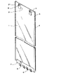
本発明を実施するために使用する遮水パネルを図1に示した例で説明する。図1は、本発明に使用する遮水パネルの一例を示す斜視図である。
図1に示した遮水パネル1は、長方形であり、その片方には雄継手2を、他方には側面縦方向にスリット(開口部)4が設けられた雌継手3を、縦方向(長手方向)に備える。本例の遮水パネル1は図2に示すように肉厚t16mm、幅2.12m、長さ8mであり、雄継手2は、図2に示すように肉厚t26mm、幅h265mmのT字型継手であり、雌継手3は、円筒形(肉厚t36mm)で、内径(空隙部の直径)h3が102.3mmで、開口幅30mmのスリット(開口部)4を側面縦方向に有する管状継手である。この雌継手3の下端は、図2に示すように下端部は封鎖されている。なお、この図では封鎖部3aは斜面状とされているが水平な封鎖部でもよい。雌継手3の下端が斜面状に封鎖されている場合は、図1に示すように、雄継手2の下端部は雌継手3のスリット4が存在する長さまでとしている。
The water shielding panel used for carrying out the present invention will be described with reference to the example shown in FIG. FIG. 1 is a perspective view showing an example of a water shielding panel used in the present invention.
1 has a rectangular shape, one side having a
なお、スリット4部は、遮水パネル1をソイルセメント壁中へ自沈する前に、例えば図2に例示すように、樹脂テープ5で封鎖する。封鎖する時期は、ソイルセメント壁中に沈設する前であればよいが、置き場に遮水パネル1が水平に置かれている場合に行うことが最も好ましい。更に、図2に示すように、雌継手3のスリット4の上方を幅広として、このV字状の部分を雄継手の挿入用ガイド4aとすることが好ましい。図2では、スリット4を明示するために樹脂テープ5がスリットを封鎖してない分離した状態の図としているが、図3に示すようにスリット4は樹脂テープ5で封鎖されているのである。
また、図1に示すように、遮水パネル1の下端部には、逆U字状のフック6が多数付けられ、先端部が閉じた状態になっている。なお、このフック6を遮水パネル1へ取り付けるために、補強板7が遮水パネル1の下端部に溶接され、この補強板7に前記したフック6が取り付けられる。このフック6は後述する打設用フレーム11の下端の遮水パネル支え手段に引っ掛けるためのものである。
図1に示すように、遮水パネル1の左右上端部には、水平な穴を有する金具8が突設されている。この金物8も遮水パネル1に溶接された補強板9の上に取り付けられている。
The
Moreover, as shown in FIG. 1, many reverse
As shown in FIG. 1,
この遮水パネル1をソイルセメント壁中へ沈設する際に使用される打設用フレーム11の例を図3に示す。この図3に示した打設用フレーム11は、幅が1.9mであり、遮水パネル1の継手部2、3を除く幅の2.06mよりも幅が狭い。しかし、長さは9mであり、長さ8mの遮水パネル1を装着した状態で、遮水パネル1が存在していない部分の長さが上方に1m存在する。なお、この例では打設用フレーム11の肉厚は、28mmである。
打設用フレーム11の上端には、ボルト14を挿通可能な孔を有する金具13が存在する。この金具13は、遮水パネル1の上方を保持するための金具であり、遮水パネル1の上方の金具8を、図3に示すように、ターンバックル15を介して遮水パネル1の上方を保持するのである。即ち、図4に要部を示すように、ターンバックル15の上端の孔部と打設用パネル11の金具13の孔にボルト14を挿通しナットを締めることにより固定し、ターンバックル15の下端側部分であるコの字状に分岐した部分に開けられた穴と遮水パネル1の上方の金具8とにボルト14を挿通し、ナットを締めることにより固定するのである。
上記したように、遮水パネル1は、その下端のフック6が打設用フレーム11のピン12に引っかかっているので、ターンバックル15を締め付けることにより、遮水パネル1が上方に引っ張られて、図5に示したように遮水パネル1が打設用パネル11に添った状態で装着することが可能になる。
FIG. 3 shows an example of a placement frame 11 used when the water shielding panel 1 is set in the soil cement wall. The casting frame 11 shown in FIG. 3 has a width of 1.9 m and is narrower than the width of 2.06 m excluding the
A
As described above, since the water-impervious panel 1 has the
また、打設用フレーム11の遮水パネル1を装着しない裏面には、図6に示すように、補強リブ16が設けられ、この補強リブ16の最上部には、打設用フレーム11を吊り下げるための吊りフック17が取り付けられている。更に補強リブ16に沿って上下に貫通する四角い筒状の通路18が設けられ、この中にグラウトを該通路18の下端より吐出できるように、該通路18の中にグラウトホース19が挿入されている。
Further, as shown in FIG. 6, a reinforcing
なお、図3に示した打設用フレーム11の上方2箇所と下方2箇所に示した吊りフック20は、打設用フレームに設けたネジ穴21に着脱自在にネジ止めされるものであり、図3のように遮水パネル1を装着する場合は、遮水パネル1を装着する面に取り付けられた吊りフック20は外されている。
遮水パネル1を装着する前や、遮水パネル1の沈設が終了した後などにおいて、打設用フレーム11を保管場所に移動させるときや、保管場所から移動させる際には、打設用フレーム11に吊りフック20を取り付けて打設用フレーム11を水平な状態で吊り下げて移動させる。
この打設用フレーム11は、ソイルセメント壁中に遮水パネル1と共に沈設され、後で遮水パネル1をソイルセメント壁中に残置させて地上に回収されるものであるから、打設用フレーム11には、遮水パネル1を保持しない状態で剥離材(もしくは剥離剤)を事前に塗布しておくことが望ましい。
The suspension hooks 20 shown in the upper two places and the lower two places of the placement frame 11 shown in FIG. 3 are detachably screwed into screw holes 21 provided in the placement frame. When mounting the water shielding panel 1 as shown in FIG. 3, the hanging
When the casting frame 11 is moved to or from the storage place before the waterproof panel 1 is mounted or after the installation of the waterproof panel 1 is completed, the casting frame is used. The
The casting frame 11 is set together with the water shielding panel 1 in the soil cement wall, and is later collected on the ground by leaving the water shielding panel 1 in the soil cement wall. 11, it is desirable to apply a release material (or release agent) in advance in a state where the water shielding panel 1 is not held.
次ぎに、本発明におけるソイルセメントの地中連続壁を構築するための装置の一例を、図7に示す。図7(a)は、ソイルセメントを構築している状態の装置を示し、図7(b)に装置の要部拡大図を示す。
このソイルセメントの地中連続壁を構築するための装置22は、掘削刃23を有する無端チェーン24が駆動ローラ25とアイドルローラ26により、カッターポスト27の周囲を回転できるようにされている構造を要部とする装置であり、このカッターポスト27はマスト28に沿って上下移動可能とされていると共に、マスト28の横移動と共に、カッターポスト27は横移動できる構造になっている。このマスト28は油圧シリンダー29により、ベースマシンのフレーム30に対し横移動可能となっていると共に、ベースマシンのクローラ31によっても横移動することが可能になっている。また、この装置22には図7(b)に示すように、下端部にセメント系固化材液の吐出口32を有するものであり、セメント系固化材液を吐出しながら、無端チェーン24を回転しながらカッターポスト27を横行させることにより、地盤を掘削しながら、掘削土とセメント系固化材液を撹拌混合してソイルセメントとするものである。このようにしてソイルセメント地中連続壁を構築できる。また、掘削刃23により掘削できる幅を、例えば550mmとすると、幅550mmで均一な幅のソイルセメント地中連続壁を構築でき、ソイルセメント地中連続壁の深さは、そのカッターポスト27の長さを構築する深さに対応できるようにすることにより、所望深さのソイルセメント地中連続壁が構築できる。
この例では、地盤の不透水層に至る深さ20mまで、幅550mmのソイルセメント遮水地中壁を構築した。
なお、前述した遮水パネルを上端の8mの深さまで沈設する予定である。上端の8mにのみに遮水パネルを存在させるのは、地震時にその上下で大きな変形が起こり得る地盤の境界面は上端の8mよりも浅い部分にしか存在せず、8mより深い部分には係る境界層が存在しない地盤であったためである。このように、この例で施工した地盤は、8mを超える部分に遮水パネルが存在しなくとも、地震時にクラックなどが発生する恐れがない地盤であり、ソイルセメントのみで遮水性が確保できる。
Next, an example of an apparatus for constructing an underground continuous wall of soil cement according to the present invention is shown in FIG. Fig.7 (a) shows the apparatus of the state which is building the soil cement, FIG.7 (b) shows the principal part enlarged view of an apparatus.
The
In this example, a soil cement impermeable ground wall with a width of 550 mm was constructed up to a depth of 20 m reaching the impermeable layer of the ground.
In addition, the water-impervious panel described above is planned to be laid down to a depth of 8 m at the upper end. The reason for having a water-impervious panel only at the top 8m is that the ground boundary where large deformation can occur at the top and bottom of the earthquake is only in the shallower part of the top 8m, and deeper than 8m. This is because the ground had no boundary layer. Thus, the ground constructed in this example is a ground where there is no possibility of cracking during an earthquake even if there is no water shielding panel in a portion exceeding 8 m, and water shielding can be ensured only with soil cement.
このようにソイルセメントの地中連続壁を構築した後、ソイルセメントが未硬化で流動性を有する時点で、前述したように遮水パネル1を打設用フレーム11に装着してソイルセメント中へ挿入するのである。
この挿入時に遮水パネル1がソイルセメントの幅の中心部に位置させるために、図8に一例を示すような挿入定規部材33を使用することが好ましい。
図8に示したように、H形鋼からなる定規受け材34をソイルセメント壁に沿って両側に設置し、挿入定規部材33が定規受け材34に沿って移動可能で、かつ任意位置で固定可能であって、ソイルセメント壁方向に張り出した部材35の先端にローラ36を有する構造となっている。このような構造を持つ一対の挿入定規部材33におけるローラ36間の幅は、打設用フレーム11と共に遮水フレーム1が通過できるようにされていると共に、遮水パネル1がソイルセメント壁の幅の中心部に位置するように調整されている。図8(a)はセットした状態を示し、(b)は遮水パネルを打設用フレームと共にソイルセメント壁中に挿入している施工状態を示している。
After the soil cement underground wall is constructed in this way, when the soil cement is uncured and has fluidity, the water shielding panel 1 is attached to the placing frame 11 as described above and into the soil cement. Insert it.
It is preferable to use an
As shown in FIG. 8,
このような挿入用定規部材33を使用し、遮水パネル1を装着した打設用フレーム11は、その最上端の吊りフック17により吊り下げた状態でソイルセメント中にその自重により沈設される。このように本発明では自沈が可能である。また、単独の沈設では、沈設作業時の曲げ剪断などにより変形しやすい薄肉幅広の遮水パネル1でも、打設用フレーム11を使用することにより変形させずに沈設できる。通常のソイルセメントでは、その部分のソイルセメント壁が構築した後、通常、2〜3時間程度まで自沈することが可能である。
この例では、沈設が完了した状態で、図9に示すように、グラウトミキサー37で混練され、グラウトポンプ38により圧送されるグラウト材がグラウトホース19を経て遮水パネル1の雌継手3内に充填される。
なお、図9に示すように遮水パネル1がソイルセメント地中壁内に入ってしまっても、打設用フレーム11の上部は地上に突出している。しかしながらソイルセメント地中壁のこちら側、即ち、打設用フレーム11が存在していないこちら側の地面に作業者が立つことができるので、作業者はグラウトポンプからのグラウトホースと打設用フレームのグラウトホースを地表面で連結することができる。
Using such an
In this example, as shown in FIG. 9, the grouting material kneaded by the
As shown in FIG. 9, even if the water shielding panel 1 enters the soil cement underground wall, the upper portion of the placement frame 11 protrudes above the ground. However, since the worker can stand on this side of the soil cement underground wall, that is, on this side where the placement frame 11 does not exist, the worker can use the grout hose from the grout pump and the placement frame. The grout hose can be connected on the ground surface.
使用するグラウト材としては、その密度がソイルセメント壁のソイルセメントの密度と同じかそれ以上であるもの等、ソイルセメント壁のソイルセメントが雌継手3内に混入することが防止できものであることが好ましく、例えば、セメント量に対し3〜5重量比のベントナイト等の粘土系材料と少量の砂とセメントと(更には、フライアッシュや流動性とさせるための混和剤等を加えて)を共に水と混練して、ポンプ注入時に砂等が分離しないようにしたものが使用される。更に硬化遅延剤を混練してグラウトの硬化を遅延させ、次の遮水パネル1の挿入可能時間を長くしたものでもよい。
また、上記のグラウト材の代わりに、土とベントナイトを水と共に混練したベントナイト混合土を充填材として使用してもよい。この場合、ベントナイト混合土は固化しないので、設置した遮水パネル1が地震時にその継手部で少し変形することを許容すると共に、継手部で変形しても充填材が破損されることがなく遮水性能を保持することができる。
The grout material to be used can prevent the soil cement wall soil cement from being mixed into the
Moreover, you may use the bentonite mixed soil which knead | mixed soil and bentonite with water instead of said grout material as a filler. In this case, since the bentonite mixed soil does not solidify, the installed water-impervious panel 1 is allowed to be slightly deformed at the joint during an earthquake, and the filler is not damaged even if deformed at the joint. Water performance can be maintained.
このように雌継手3内に充填材を充填させた後に、次ぎに連結すべき遮水パネル1を打設用フレーム11と共にソイルセメント中に自沈させる。
この場合、図10に示すように、遮水パネル1の充填材が充填された遮水パネル1の雌継手3に、次の遮水パネル1におけるT字状の雄継手2が入るようにして自沈される。図10においては中央の遮水パネル1が次に挿入された遮水パネルである。
図11(a)(b)(c)は施工工程における雌継手3を示す拡大平面説明図である。
図11(a)においては、挿入済みの遮水パネル1の充填材が充填された遮水パネル1の雌継手3と、次ぎに挿入される遮水パネル1の雄継手2を破線で示している。
次の遮水パネル1における雄継手の挿入により、雌継手3のスリット4を封鎖していた封鎖材(この例では樹脂テープ5)は破断されることになるが、図11(b)に示すように雌継手3内に充填された充填材は、ソイルセメント壁のソイルセメントの液比重以上にすることにより、ソイルセメント壁のソイルセメントが雌継手3内に混入する(即ち、充填材とソイルセメントの液圧差により雌継手3内に混入する)ことが防止でき、ソイルセメントが硬化した状態での継手部2、3の状態を図11(c)に示したように、継手3内に最初に充填した充填材を残存させることができる。
このようにして構築したソイルセメントの地中連続壁中に次々に連結すべき遮水パネル1を打設用フレーム11と共にソイルセメント中に沈設する工程と雌継手3内へのグラウト材の注入を繰り返す。
After filling the female joint 3 with the filler in this way, the water-impervious panel 1 to be connected next is self- sunk in the soil cement together with the placing frame 11.
In this case, as shown in FIG. 10, the T-shaped male joint 2 in the next water shielding panel 1 is inserted into the
11A, 11B, and 11C are enlarged plan explanatory views showing the female joint 3 in the construction process.
In Fig.11 (a), the
The sealing material (in this example, the resin tape 5) that has sealed the
The steps of sinking the water shielding panels 1 to be connected one after another into the soil cement continuous wall thus constructed in the soil cement together with the casting frame 11 and the injection of the grout material into the female joint 3 are carried out. repeat.
その後にソイルセメントの凝結が進み、打設用フレーム11を引き上げても、ソイルセメント中に残置される遮水パネル1が厚さ方向に移動しなくなるようになる(通常はソイルセメントの築造後3時間を超え4時間程度でこの状態になる)と、図12に示すように、打設用フレーム11を、そのグラウト注入路18からグラウトを注入しながら順次地上に引き上げる。即ち、グラウトミキサー37で混練され、グラウトポンプ38により圧送されるグラウト材が、打設用フレーム11の通路18の中に存在するグラウトホース19を経て、打設用フレーム11が引き上げられた容積分のグラウト材が、打設用フレーム11の下方先端部から吐出さる。
この例の場合、グラウト材として調達しやすいセメントミルクが使用される。このセメントミルクは固化後の強度が固化後のソイルセメントの強度と同等であるかそれ以上になるものであることが好ましい。
このようにして全ての打設用フレーム11を引き上げることにより、図13に示すように、継手部に充填材が存在する状態で、互いに連接された幅が広くて薄肉の遮水パネル1を幅方向中央部に存在させたソイルセメント地中連続壁を構築することができる。
Thereafter, the setting of the soil cement progresses, and even if the casting frame 11 is pulled up, the water shielding panel 1 left in the soil cement does not move in the thickness direction (usually after the construction of the
In this example, cement milk that is easy to procure as a grout material is used. The cement milk preferably has a strength after solidification that is equal to or higher than the strength of the soil cement after solidification.
By pulling up all the placing frames 11 in this way, as shown in FIG. 13, the wide and thin water-impervious panels 1 connected to each other in the state where the filler is present in the joint portion are widened. Soil cement underground continuous wall can be constructed in the center of the direction.
なお、昼休みなど施工中断時間が短い場合は、その直前に沈設した打設用フレーム11を引き上げることなく、この打設用フレーム11に装着された遮水パネル1の雌継手3内に充填材を入れた状態でソイルセメント中に残存させて、再開時に次の遮水パネル1を打設用フレーム11と共に自沈させた後に、中断前に沈設した打設用フレーム11を先端からグラウト材を吐出しつつ引き上げることも可能である。
なお図14にはクレーンにて打設用フレーム11を引き上げる状態を示している。図14には明視されていないが、この場合でも図12に示したように、打設用フレーム11の下端からグラウト材を吐出しつつ引き上げるのである。
更に、次の工程が翌日になるなどの理由で、中断前に沈設した打設用フレーム11を工事再開後に引き上げることが困難になる場合は、中断前に全ての打設用フレーム11を全て引き上げる。勿論、この際、打設用フレーム11を先端からグラウト材を吐出しつつ引き上げるのである。
In addition, when construction interruption time is short, such as a lunch break, a filler is put in the
FIG. 14 shows a state in which the placing frame 11 is pulled up by a crane. Although not clearly shown in FIG. 14, even in this case, as shown in FIG. 12, the grout material is pulled up and discharged from the lower end of the placing frame 11.
Furthermore, if it becomes difficult to pull up the placement frame 11 that was laid before the interruption after resuming the construction because the next process will be the next day, all the placement frames 11 are raised before the interruption. . Of course, at this time, the placement frame 11 is pulled up while discharging the grout material from the tip.
このように、次の工程が中断する場合は、図14に示すように、ソイルセメントの当日分の地中連続壁を構築した後、図7(a)(b)に示した装置22からセメント系固化材液の代わりに水を加えたベントナイトの泥状物を吐出しながら無端チェーン24を循環させて横行させることにより、退避掘削を行う。この固化することがないベントナイトと掘削土が混合された退避掘削内に装置22を位置させておくことにより、翌日のソイルセメント地中連続壁の施工が可能になる。なお、この退避掘削を行う直前に沈設した打設用フレーム11は遮水パネル1と共にソイルセメント中に残存させ、退避掘削が進んだ段階で最後の打設用フレーム11を引き上げることが好ましい。
このように全ての打設用フレーム11を引き上げても、翌日以降に施工を再開するまでに、ソイルセメントの固化が進み、遮水パネル1が翌日以降の施工再開時に、変形を受けなくなる。
そこで装置22を、セメント系固化材液を吐出させながら無端チェーン24を循環させながら前に構築済みのソイルセメント地中連続壁方向に横行させることにより、前のソイルセメント地中連続壁に連続したソイルセメントとし、その後、逆方向に装置22を、セメント系固化材液を吐出させながら無端チェーン24を循環させながら横行させることにより、前に構築したソイルセメント地中連続壁に連続するソイルセメント地中壁を構築し、前述した工程により、打設用フレーム11を使用して、遮水パネル1を自沈させる。
Thus, when the next process is interrupted, as shown in FIG. 14, after constructing the underground continuous wall for the day of soil cement, the cement is removed from the
Thus, even if all the placement frames 11 are pulled up, solidification of the soil cement proceeds until the construction is resumed after the next day, and the water shielding panel 1 is not deformed when the construction is resumed after the next day.
Therefore, the
以上に示したように、本発明方法によって、、即ち、ソイルセメントの地中連続壁を構築後、ソイルセメントが未硬化で流動性を有する間に、雌雄の継手部を有する幅が広くて薄肉の遮水パネルを打設用フレームと共にソイルセメント中へ挿入し、地中連続壁中で前記遮水パネルの両側にソイルセメント壁が存在する遮水地中壁を構築する方法であって、打設用フレームは、遮水パネルの継手部を除く部分よりも幅狭であって、肉厚の鋼製のものであり、その下方に遮水パネルを支える手段を備え、その上方に遮水パネルを保持開放自在な手段を備えると共に、該打設用フレームの遮水パネルを支える面の反対側にはグラウト注入路が装備されたものであり、前記遮水パネルが幅1.8〜2.5mの広幅薄肉鋼製パネルであり、片方に雌継手、他の片方に雄継手を有し、雌継手は最下端が封鎖されたものであり、かつ雌継手と雄継手とは密に係合せずに互いに係合し得る構造のものであり、上記遮水パネルの雌継手部における側面開口部を、ソイルセメントに挿入される前に、雄継手の上方からの挿入により破断される強度の材料で封鎖し、前記遮水パネルを打設用フレームに装着した状態でソイルセメント中に自沈させ、雌継手内に充填材を充填し、この雌継手側に雄継手を有する遮水パネルを打設用フレームに装着した状態でソイルセメント中に自沈させ、この後から挿入した雌継手内に充填材を充填するという工程を繰り返し、その後に打設用フレームを、そのグラウト注入路からグラウトを注入しながら地上に引き上げることにより、遮水パネルを有する遮水地中壁を構築することができる。 As described above, according to the method of the present invention, that is, after the soil cement underground wall is constructed, while the soil cement is uncured and has fluidity, the male and female joint portions are wide and thin. A water impervious panel is inserted into a soil cement together with a casting frame, and a water impervious underground wall having soil cement walls on both sides of the water impervious panel in the underground continuous wall is constructed. The installation frame is narrower than the portion excluding the joint portion of the water-impervious panel and is made of thick steel, and is provided with means for supporting the water-impervious panel below the water-impervious panel. And a grouting channel on the opposite side of the surface for supporting the water shielding panel of the placing frame, and the water shielding panel has a width of 1.8-2. a wide thin-walled steel panel of 5m, female joints to one side The other end has a male joint, the female joint is sealed at the lowermost end, and the female joint and the male joint can be engaged with each other without being closely engaged. The side opening in the female joint of the water panel is sealed with a material that can be broken by the insertion from above the male joint before being inserted into the soil cement, and the water blocking panel is attached to the casting frame. In this state, it is allowed to self-sink in the soil cement, the female joint is filled with a filler, and a water-impervious panel having a male joint on the female joint side is attached to the casting frame to be self- sunk in the soil cement. A water-impervious area having a water-impervious panel by repeating the process of filling the female joint inserted later with filling material, and then pulling the casting frame up to the ground while injecting grout from the grout injection path. Build the inner wall Rukoto can.
1 遮水パネル
2 雄継手
3 雌継手
3a 雌継手下端の封鎖部
4 雌継手の側面開口部(スリット)
4a 挿入用ガイド
5 樹脂テープ
6 フック
7、9 補強板
8 金具
11 打設用フレーム
12 ピン
13 金具
15 ターンバックル
16 補強リブ
17 吊りフック
18 通路(グラウト注入路)
19 グラウトホース
22 ソイルセメントの地中連続壁を構築する装置
23 掘削刃
24 無端チェーン
27 カッターポスト
32 吐出口
33 挿入定規部材
36 ローラ
DESCRIPTION OF SYMBOLS 1 Water-
19
Claims (4)
打設用フレームは、遮水パネルの継手部を除く部分よりも幅狭であって、肉厚の鋼製のものであり、その下方に遮水パネルを支える手段を備え、その上方に遮水パネルを保持開放自在な手段を備えると共に、該打設用フレームの遮水パネルを支える面の反対側にはグラウト注入路が装備されたものであり、
前記遮水パネルが幅1.8〜2.5mの広幅薄肉鋼製パネルであり、片方に雌継手、他方に雄継手を有し、雌継手は最下端が封鎖されたものであり、かつ雌継手と雄継手とは密に係合せずに互いに係合し得る構造のものであり、
上記遮水パネルの雌継手の側面に設けられた側面開口部を、ソイルセメントに挿入される前に、雄継手の上方からの挿入により破断される強度の材料で封鎖し、
前記遮水パネルを打設用フレームに装着した状態でソイルセメント中に自沈させつつ、または自沈した後に、雌継手内に充填材を充填し、この雌継手に係合する雄継手を有する次の遮水パネルを打設用フレームに装着した状態でソイルセメント中に自沈させつつ、または自沈した後に、次の遮水パネルの雌継手内に充填材を充填するという工程を繰り返し、
その後に打設用フレームを、そのグラウト注入路からグラウトを注入しながら地上に引き上げることを特徴とする遮水地中壁の構築方法。 After construction of the soil cement underground wall, while the soil cement is uncured and fluid, insert a wide and thin water-impervious panel with male and female joints into the soil cement along with the casting frame. A method for constructing a water-impervious underground wall in which soil cement walls exist on both sides of the water-impervious panel in the underground continuous wall,
The casting frame is narrower than the portion excluding the joint portion of the water-impervious panel and is made of thick steel, and is provided with means for supporting the water-impervious panel below, and the water shield above it. A means for holding and releasing the panel is provided, and a grout injection path is provided on the opposite side of the surface for supporting the water shielding panel of the placing frame.
The water-impervious panel is a wide thin steel panel having a width of 1.8 to 2.5 m , having a female joint on one side and a male joint on the other, the female joint being sealed at the lowermost end, and female The joint and the male joint are of a structure that can engage with each other without closely engaging,
Before the side opening provided on the side surface of the female joint of the water shielding panel is inserted into the soil cement, it is sealed with a material having a strength that is broken by insertion from above the male joint,
The self-sinking in the soil cement with the water-impervious panel attached to the casting frame, or after self-sinking , the female joint is filled with a filler and has a male joint that engages with the female joint. While self-sinking in the soil cement with the water-impervious panel attached to the casting frame, or after self-sinking , repeat the process of filling the filler in the female joint of the next water-impervious panel,
A method for constructing a water-impervious middle wall characterized in that the casting frame is then pulled up to the ground while injecting grout from the grout injection path.
Priority Applications (1)
| Application Number | Priority Date | Filing Date | Title |
|---|---|---|---|
| JP2004183176A JP4262640B2 (en) | 2004-06-22 | 2004-06-22 | Construction method of the impervious wall |
Applications Claiming Priority (1)
| Application Number | Priority Date | Filing Date | Title |
|---|---|---|---|
| JP2004183176A JP4262640B2 (en) | 2004-06-22 | 2004-06-22 | Construction method of the impervious wall |
Publications (2)
| Publication Number | Publication Date |
|---|---|
| JP2006009242A JP2006009242A (en) | 2006-01-12 |
| JP4262640B2 true JP4262640B2 (en) | 2009-05-13 |
Family
ID=35776780
Family Applications (1)
| Application Number | Title | Priority Date | Filing Date |
|---|---|---|---|
| JP2004183176A Expired - Fee Related JP4262640B2 (en) | 2004-06-22 | 2004-06-22 | Construction method of the impervious wall |
Country Status (1)
| Country | Link |
|---|---|
| JP (1) | JP4262640B2 (en) |
Families Citing this family (9)
| Publication number | Priority date | Publication date | Assignee | Title |
|---|---|---|---|---|
| JP4890085B2 (en) * | 2006-04-21 | 2012-03-07 | 新日本製鐵株式会社 | Method for constructing joint fitting part of impermeable wall, impermeable wall material, female joint and male joint |
| JP4882096B2 (en) * | 2007-03-16 | 2012-02-22 | 株式会社テノックス | Implant for filling joint of water-impervious wall material and construction method of impermeable wall using the injection |
| JP5966162B2 (en) * | 2012-04-25 | 2016-08-10 | 西武ポリマ化成株式会社 | Steel pipe sheet pile watertight joint structure |
| JP7007747B2 (en) * | 2019-01-09 | 2022-01-25 | 野原工業株式会社 | Ridge waterproof wall construction equipment and ridge waterproof wall construction method |
| CN109826237A (en) * | 2019-02-11 | 2019-05-31 | 中国水电基础局有限公司 | A kind of tooling and method using HDPE film piece construction composite anti-penetrating diaphram wall |
| JP7217034B2 (en) * | 2020-08-03 | 2023-02-02 | 野原工業株式会社 | Construction device for ridge waterproof wall |
| CN113463639B (en) * | 2021-07-07 | 2022-06-03 | 南京东土建设科技有限公司 | Underground continuous wall distributed grouting system |
| CN114508093A (en) * | 2022-02-11 | 2022-05-17 | 中冶华南建设工程有限公司 | Construction process of ultra-deep underground diaphragm wall |
| KR102526697B1 (en) * | 2022-11-17 | 2023-04-28 | 주식회사 골든포우 | Water blocking construction method for blocking oil pollutants using smart barrier material and panel embedding method |
Family Cites Families (4)
| Publication number | Priority date | Publication date | Assignee | Title |
|---|---|---|---|---|
| JPS4949404A (en) * | 1972-09-16 | 1974-05-14 | ||
| JPH0729017U (en) * | 1993-04-20 | 1995-06-02 | 東亜建設工業株式会社 | Sediment intrusion prevention plate in steel pipe sheet pile joint |
| JP3583020B2 (en) * | 1999-05-11 | 2004-10-27 | 不動建設株式会社 | Underground barrier plate construction method |
| JP3943787B2 (en) * | 2000-01-26 | 2007-07-11 | 新日本製鐵株式会社 | Sheet pile with stiffening frame, its construction method and construction method of underground continuous wall |
-
2004
- 2004-06-22 JP JP2004183176A patent/JP4262640B2/en not_active Expired - Fee Related
Also Published As
| Publication number | Publication date |
|---|---|
| JP2006009242A (en) | 2006-01-12 |
Similar Documents
| Publication | Publication Date | Title |
|---|---|---|
| JP2016014290A (en) | Temporary shutoff method of existing underwater structure | |
| JP4262640B2 (en) | Construction method of the impervious wall | |
| US4146348A (en) | Method for executing impermeable construction joints for diaphragm walls | |
| CN113266392B (en) | Pipe jacking construction method for penetrating through existing anchor cable group | |
| CN112160324A (en) | Construction method for deep foundation pit support | |
| CN106545020A (en) | A kind of construction method of deep foundation pit support | |
| CN110206071A (en) | A kind of diaphram wall seam reinforcement means and device | |
| CN107542065B (en) | Construction method for overturning and lifting small steel die of high-steep-clearance groove | |
| CN110258600A (en) | A kind of vertical cofferdam construction engineering method suitable for deep water waters | |
| CN107587476B (en) | Wave-blocking wall with prefabricated reverse arc olecranon structure and design and construction method thereof | |
| JP2009264036A (en) | Method for reinforcing bridge pier or the like | |
| US5871307A (en) | Pre-cast concrete panel wall | |
| CN115045310A (en) | Steel pipe pile cofferdam construction method | |
| CN114607187B (en) | Shaft type underground parking garage construction method of cast-in-situ supporting structure under slurry | |
| TW200930863A (en) | Construction method for T-shaped interface connecting case of diaphragm wall and buttress wall or cross wall | |
| CN113585237B (en) | Diaphragm wall joint and diaphragm wall construction method | |
| NL1008594C2 (en) | Building a floor by pouring concrete into foundation pit enclosed by dam walls | |
| EP1964981A1 (en) | Reinforcement elements for in-situ cast walls and method to excavate in situ cast walls | |
| CN217710670U (en) | Steel box girder underground continuous wall structure | |
| GB2571097A (en) | Shear key former apparatus and method(s) | |
| CN217325434U (en) | Deepwater steel sheet pile cofferdam in rock stratum region | |
| JP2002146775A (en) | Diaphragm-wall construction method | |
| CN209798737U (en) | Prefabricated ground is wall structure even | |
| CN109914475B (en) | Construction method for excavating self-supporting prefabricated pipe gallery | |
| KR102016366B1 (en) | File head trimming device and trimming method for CIP concrete pile |
Legal Events
| Date | Code | Title | Description |
|---|---|---|---|
| A621 | Written request for application examination |
Free format text: JAPANESE INTERMEDIATE CODE: A621 Effective date: 20060831 |
|
| A977 | Report on retrieval |
Free format text: JAPANESE INTERMEDIATE CODE: A971007 Effective date: 20080618 |
|
| A131 | Notification of reasons for refusal |
Free format text: JAPANESE INTERMEDIATE CODE: A131 Effective date: 20080620 |
|
| A521 | Written amendment |
Free format text: JAPANESE INTERMEDIATE CODE: A523 Effective date: 20080818 |
|
| TRDD | Decision of grant or rejection written | ||
| A01 | Written decision to grant a patent or to grant a registration (utility model) |
Free format text: JAPANESE INTERMEDIATE CODE: A01 Effective date: 20090109 |
|
| A01 | Written decision to grant a patent or to grant a registration (utility model) |
Free format text: JAPANESE INTERMEDIATE CODE: A01 |
|
| A61 | First payment of annual fees (during grant procedure) |
Free format text: JAPANESE INTERMEDIATE CODE: A61 Effective date: 20090209 |
|
| FPAY | Renewal fee payment (event date is renewal date of database) |
Free format text: PAYMENT UNTIL: 20120220 Year of fee payment: 3 |
|
| R150 | Certificate of patent or registration of utility model |
Ref document number: 4262640 Country of ref document: JP Free format text: JAPANESE INTERMEDIATE CODE: R150 Free format text: JAPANESE INTERMEDIATE CODE: R150 |
|
| FPAY | Renewal fee payment (event date is renewal date of database) |
Free format text: PAYMENT UNTIL: 20130220 Year of fee payment: 4 |
|
| R250 | Receipt of annual fees |
Free format text: JAPANESE INTERMEDIATE CODE: R250 |
|
| FPAY | Renewal fee payment (event date is renewal date of database) |
Free format text: PAYMENT UNTIL: 20130220 Year of fee payment: 4 |
|
| S531 | Written request for registration of change of domicile |
Free format text: JAPANESE INTERMEDIATE CODE: R313531 |
|
| R350 | Written notification of registration of transfer |
Free format text: JAPANESE INTERMEDIATE CODE: R350 |
|
| FPAY | Renewal fee payment (event date is renewal date of database) |
Free format text: PAYMENT UNTIL: 20130220 Year of fee payment: 4 |
|
| S533 | Written request for registration of change of name |
Free format text: JAPANESE INTERMEDIATE CODE: R313533 |
|
| FPAY | Renewal fee payment (event date is renewal date of database) |
Free format text: PAYMENT UNTIL: 20130220 Year of fee payment: 4 |
|
| R350 | Written notification of registration of transfer |
Free format text: JAPANESE INTERMEDIATE CODE: R350 |
|
| FPAY | Renewal fee payment (event date is renewal date of database) |
Free format text: PAYMENT UNTIL: 20140220 Year of fee payment: 5 |
|
| R250 | Receipt of annual fees |
Free format text: JAPANESE INTERMEDIATE CODE: R250 |
|
| R250 | Receipt of annual fees |
Free format text: JAPANESE INTERMEDIATE CODE: R250 |
|
| S111 | Request for change of ownership or part of ownership |
Free format text: JAPANESE INTERMEDIATE CODE: R313117 |
|
| R350 | Written notification of registration of transfer |
Free format text: JAPANESE INTERMEDIATE CODE: R350 |
|
| S533 | Written request for registration of change of name |
Free format text: JAPANESE INTERMEDIATE CODE: R313533 |
|
| R350 | Written notification of registration of transfer |
Free format text: JAPANESE INTERMEDIATE CODE: R350 |
|
| LAPS | Cancellation because of no payment of annual fees |