JP4261341B2 - Industrial fabric including yarn assembly - Google Patents
Industrial fabric including yarn assembly Download PDFInfo
- Publication number
- JP4261341B2 JP4261341B2 JP2003510488A JP2003510488A JP4261341B2 JP 4261341 B2 JP4261341 B2 JP 4261341B2 JP 2003510488 A JP2003510488 A JP 2003510488A JP 2003510488 A JP2003510488 A JP 2003510488A JP 4261341 B2 JP4261341 B2 JP 4261341B2
- Authority
- JP
- Japan
- Prior art keywords
- yarn
- yarns
- fabric
- laminated
- warp
- Prior art date
- Legal status (The legal status is an assumption and is not a legal conclusion. Google has not performed a legal analysis and makes no representation as to the accuracy of the status listed.)
- Expired - Fee Related
Links
Images


Classifications
-
- D—TEXTILES; PAPER
- D21—PAPER-MAKING; PRODUCTION OF CELLULOSE
- D21F—PAPER-MAKING MACHINES; METHODS OF PRODUCING PAPER THEREON
- D21F1/00—Wet end of machines for making continuous webs of paper
- D21F1/0027—Screen-cloths
- D21F1/0036—Multi-layer screen-cloths
- D21F1/0045—Triple layer fabrics
-
- D—TEXTILES; PAPER
- D03—WEAVING
- D03D—WOVEN FABRICS; METHODS OF WEAVING; LOOMS
- D03D11/00—Double or multi-ply fabrics not otherwise provided for
-
- D—TEXTILES; PAPER
- D03—WEAVING
- D03D—WOVEN FABRICS; METHODS OF WEAVING; LOOMS
- D03D13/00—Woven fabrics characterised by the special disposition of the warp or weft threads, e.g. with curved weft threads, with discontinuous warp threads, with diagonal warp or weft
- D03D13/004—Woven fabrics characterised by the special disposition of the warp or weft threads, e.g. with curved weft threads, with discontinuous warp threads, with diagonal warp or weft with weave pattern being non-standard or providing special effects
-
- D—TEXTILES; PAPER
- D21—PAPER-MAKING; PRODUCTION OF CELLULOSE
- D21F—PAPER-MAKING MACHINES; METHODS OF PRODUCING PAPER THEREON
- D21F1/00—Wet end of machines for making continuous webs of paper
- D21F1/0027—Screen-cloths
-
- D—TEXTILES; PAPER
- D21—PAPER-MAKING; PRODUCTION OF CELLULOSE
- D21F—PAPER-MAKING MACHINES; METHODS OF PRODUCING PAPER THEREON
- D21F1/00—Wet end of machines for making continuous webs of paper
- D21F1/0027—Screen-cloths
- D21F1/0054—Seams thereof
Abstract
Description
本発明は、一般に、縦糸の組織及び横糸の組織の一方または両方が、実質的に工業用ファブリック中の製織経路全体にわたって、概して、連続的に隣接して互いに接触するように組織化され配列されている、少なくとも第1の糸及び第2の糸によって形成された糸アセンブリからなり、少なくとも1つの横糸の組織及び少なくとも1つの縦糸の組織を有する製織された工業用ファブリックに関する。上記糸アセンブリを形成する糸の構成、方向、表面特性及び形状は、最終用途の要求に合うように選択することができる。 In general, the present invention is organized and arranged so that one or both of the warp and weft structures are generally continuously adjacent and in contact with each other throughout the entire weaving path in the industrial fabric. A woven industrial fabric comprising a yarn assembly formed by at least a first yarn and a second yarn, and having at least one weft texture and at least one warp texture. The configuration, orientation, surface characteristics, and shape of the yarns forming the yarn assembly can be selected to meet the end use requirements.
本発明は、特に、製紙や、製紙機械等の中において、ウェブ(web)を成形、脱水及び搬送する際に補助するための関連するろ過用途に適している、改良された工業用ファブリックに関する。製紙機械用のファブリックの要求及び好ましい特性は、上記ファブリックが使用されようとする上記製紙機械の特定の部分及び製造される紙製品により変化する。それらのファブリックの大部分は、製織構造からなる。単層構造、二重層構造あるいは三重層構造を有する多くの種類のものが公知である。それらのファブリックは、公知の技術に従って、平坦またはエンドレスに製織されており、また、上記製紙機械への設置を容易にするために継ぎ合わされている。 The present invention relates to an improved industrial fabric that is particularly suitable for related filtration applications to assist in shaping, dewatering and conveying webs in papermaking, papermaking machines and the like. The requirements and preferred characteristics of a fabric for a paper machine will vary depending on the particular part of the paper machine where the fabric is to be used and the paper product being manufactured. Most of these fabrics consist of a woven structure. Many types having a single layer structure, a double layer structure or a triple layer structure are known. The fabrics are woven flat or endless according to known techniques and are spliced together to facilitate installation on the papermaking machine.
製紙機械のファブリックは、一般に、多くの物理的要求を同時に満たさなければならず、すなわち、該ファブリックは、寸法が安定していなければならず、また、該ファブリックがさらされる応力に耐えるために、適度に高い引っ張り強度を有していなければならず、該ファブリックは、高温及び高圧縮負荷に耐えなければならず、さらに該ファブリックは、上記機械の支持面上で該ファブリックの動きによって生じる摩耗の影響に適度に耐えなければならない。他の要求も知られている。それらの要求のうちの少なくともいくつかを満たすために、製紙機械のファブリックの製造会社は、ファブリック面の一方または両面を最終用途条件のためにカスタマイズすることができる、様々な製織デザイン及びファブリック構造を開発してきた。その実行のための1つの方法は、上記縦糸の組織及び横糸の組織の一方または両方における上記糸を、各組織の個々の糸が、互いに垂直方向に位置合わせされるように積層することである。 Paper machine fabrics generally have to meet many physical requirements simultaneously, i.e. the fabric must be dimensionally stable and withstand the stress to which the fabric is exposed. It must have a reasonably high tensile strength, the fabric must withstand high temperatures and high compressive loads, and the fabric will resist wear caused by movement of the fabric on the support surface of the machine. You must withstand the effects reasonably. Other requirements are also known. In order to meet at least some of those requirements, papermakers fabric manufacturers have various weaving designs and fabric structures that can customize one or both sides of the fabric surface for end use conditions. Have been developing. One way to do this is to stack the yarns in one or both of the warp and weft fabrics so that the individual yarns of each tissue are vertically aligned with each other. .
積層された縦糸および/または横糸からなる工業用製織ファブリックは公知である。例えば、Gaisserに対する米国特許第5,066,532号明細書及び同第5,857,497号明細書、Leeに対する米国特許第5,167,261号明細書、同第5,092,373号明細書及び同第5,230,371号明細書、Crosbyらに対する米国特許第6,158,478号明細書、Josefらに対する米国特許第5,503,196号明細書、およびKositzkeに対する米国特許第5,503,196号明細書を参照。その他のものも知られており用いられる。該積層された縦糸および/または横糸からなる公知のファブリックは、少なくとも二重層構造であり、該構造が、縦糸または横糸の一方または両方からなる少なくとも2つの組織を有するということになる。これらの公知のファブリックにおいて、一方の糸の組織からの上記縦糸または横糸の一方または両方の少なくとも一部は、上記製織ファブリック構造における上記第2の糸の組織において、対応するファブリックの上で垂直方向に積層された関係になるように、製織パターンで配列されている。 Industrial woven fabrics consisting of laminated warp and / or weft yarns are known. For example, US Pat. Nos. 5,066,532 and 5,857,497 to Gaisser, US Pat. Nos. 5,167,261 and 5,092,373 to Lee. And US Pat. No. 5,230,371, US Pat. No. 6,158,478 to Crosby et al., US Pat. No. 5,503,196 to Josef et al., And US Pat. No. 5, Kositzke , 503,196. Others are also known and used. The known fabric consisting of the laminated warp and / or weft is at least a double layer structure, which means that the structure has at least two textures consisting of one or both of the warp and / or weft. In these known fabrics, at least a portion of one or both of the warp or weft from one yarn structure is perpendicular to the corresponding fabric in the second yarn structure in the woven fabric structure. Are arranged in a weaving pattern so as to have a laminated relationship.
一方の組織の構成糸の少なくとも一部の各々が、第2の組織の対応する糸上に垂直方向に積層されて、例えばペアを形成する、全ての公知のファブリックにおいては、ペアの構成糸は、該ファブリックにおける全経路長に対して密接に接触していない。そこには常に、製織の繰り返しにおける積層されたペアの間に配列された、少なくとも1つの介在する糸がある。これは、それらの従来のファブリックの少なくともいくつかの上記製織パターンが、この位置で一方が他方の上に保持されるように、該積層された糸をそれらの垂直方向に安定させるようにデザインされているからである。 In all known fabrics in which at least some of the constituent yarns of one structure are each vertically stacked on the corresponding yarns of the second structure to form a pair, for example, , Not in intimate contact with the entire path length in the fabric. There is always at least one intervening yarn arranged between stacked pairs in a weaving iteration. This is designed to stabilize the laminated yarns in their vertical direction so that at least some of the above weaving patterns of their conventional fabrics are held one above the other in this position. Because.
上記縦糸および/または横糸が垂直方向に積層されている従来のファブリックは、上記構成糸の少なくとも一部が積層されていない他のファブリックよりも、多くの利点を備えている。例えば、該積層された糸の製織経路は、一方の糸の組織が、一方のファブリック面のみの一部を形成するとともに、他方の糸の組織が、反対側のファブリック面の一部を形成するように配列することができる。この構成は、その効力を有する寿命を延ばすために、耐熱または耐摩耗材を上記ファブリックの一方の面上に配置するのに利用できる。ある製織構造においては、積層された糸の組織を有するファブリックは、糸の組織が積層されていないファブリックと比較した場合に、改良された継ぎ合わせ強度及び低減された継ぎ合わせマーキングを実現できる。また、安定したファブリック構造において比較的高い透気度及び開放領域、非積層デザインと比較した場合に、増加したファブリック表面領域の接触及び円滑性、およびファブリックの縦糸充填の向上を実現することも可能である。従って、従来技術においては、積層された糸組織を有するファブリックが、構成糸が非積層関係で配列されているファブリックと比較して、その意図された最終用途により、多くの利点をもたらすことができることが認識される。 Conventional fabrics in which the warp and / or weft yarns are laminated in the vertical direction have many advantages over other fabrics in which at least some of the constituent yarns are not laminated. For example, in the weaving path of the laminated yarns, one yarn structure forms part of only one fabric surface and the other yarn structure forms part of the opposite fabric surface. Can be arranged as follows. This configuration can be used to place a heat or wear resistant material on one side of the fabric to extend its useful life. In some woven structures, a fabric having a laminated yarn structure can provide improved seam strength and reduced seam marking when compared to a fabric without a yarn structure. It is also possible to achieve increased fabric surface area contact and smoothness, and improved fabric warp filling when compared to a relatively high air permeability and open area, non-laminated design in a stable fabric structure It is. Thus, in the prior art, a fabric having a laminated yarn structure can provide a number of advantages depending on its intended end use compared to a fabric in which the constituent yarns are arranged in a non-laminated relationship. Is recognized.
しかし、現在、それらの公知のファブリックが、上記構成糸が配列される方法によるいくつかの制約を受けることが認識されている。まず第一に、一方の糸組織の構成糸の1つを一方のファブリック面上の大部分に配列できるようにして、上記第2の糸組織の構成糸を上記反対側のファブリック面上の大部分に配列する、利用可能な製織デザインの数は、多少限定される。第二に、上記反対側のファブリック端部を接合するための高強度、低継ぎ合わせマーキングを生成する、それら従来のファブリック構造に用いることができる継ぎ合わせデザインの数も限定される。第三に、単層のファブリック(縦糸及び横糸の単一の組織を有するもの)においては、(例えば、一方の表面に、コーティングを施したり、あるいは、非製織芯またはフィルム等の素材からなる追加的な層を施すことにより)上記ファブリックを後処理することなく、異なる糸材を、該ファブリック表面の各々の上に設けることは不可能である。 However, it is now recognized that these known fabrics are subject to some limitations due to the way in which the constituent yarns are arranged. First of all, one of the constituent yarns of one yarn structure can be arranged over most of one fabric surface, and the constituent yarn of the second yarn structure is arranged on the opposite fabric surface. The number of available weaving designs arranged in the part is somewhat limited. Secondly, the number of seam designs that can be used in those conventional fabric structures that produce high strength, low seam markings to join the opposite fabric ends is also limited. Third, in single-layer fabrics (those with a single structure of warp and weft) (for example, one surface is coated or added from a non-woven core or film material) It is not possible to provide different yarns on each of the fabric surfaces without post-treating the fabric (by applying a typical layer).
従って、2つの対向するファブリック表面を異ならせることが可能な、選択されたデザインからなる工業用製織ファブリックを形成できる場合には、上記継ぎ合わせが、シートを汚す可能性を低減し、かつ高強度であり、継ぎ目ループを該ファブリックの平面に対して直交させることができ、かつ改善された経済的な製造も提供することが望ましいであろう。 Thus, if the industrial woven fabric of the selected design can be made with two opposing fabric surfaces different, the splicing reduces the possibility of soiling the sheet and has high strength It would be desirable to be able to make the seam loop orthogonal to the plane of the fabric and also provide improved economic manufacturing.
従って、本発明は、その構造が、上述した従来の欠点を少なくとも改善しようとする、工業用ファブリック、特に、製紙機械のファブリックまたはろ過ファブリックを提供しようとするものである。 The present invention therefore seeks to provide an industrial fabric, in particular a papermaking machine fabric or filtration fabric, whose structure seeks to at least remedy the above-mentioned conventional drawbacks.
現在、複数の糸アセンブリを用いて工業用ファブリックを製織または構成することが可能であることがわかっている。該糸アセンブリは、上記ファブリックにおける縦糸組織及び横糸組織のいずれかまたは両方として用いることができる。各糸アセンブリは、他方の組織からの糸が、上記ファブリックのどの糸部材の間にも介在していない状態で、該工業用ファブリックの全体において、製織経路全体にわたって、概して連続的に接触するように配列されている、少なくとも2つの糸部材で構成される。 It has now been found that it is possible to weave or construct an industrial fabric using multiple yarn assemblies. The yarn assembly can be used as either or both of the warp and weft structures in the fabric. Each yarn assembly is generally in continuous contact throughout the weaving path in the entire industrial fabric, with no yarn from the other tissue interposed between any yarn members of the fabric. Are composed of at least two thread members.
第1の主要な実施形態において、本発明は、複数の横糸と織り合わされた複数の縦糸を備える、製織された工業用ファブリックであって、
a)前記複数の縦糸の少なくとも一部が、複数の糸アセンブリを含み、
b)前記複数の糸アセンブリの各々が、少なくとも第1及び第2の糸で構成されており、
c)前記第1及び第2の糸が、ファブリック面に対してほぼ垂直方向に重ねられ、かつ実質的に前記ファブリックの全体にわたって、互いに概して連続かつ隣接して接触するように、前記製織されたファブリック内に配列されている製織された工業用ファブリックを提供する。
In a first principal embodiment, the present invention comprises a plurality of warp yarns interwoven with a plurality of weft yarns, a industrial fabric has been woven,
a) at least a portion of said plurality of warp yarns comprises a plurality of yarn assemblies,
b) each of the plurality of yarn assemblies, are composed of at least first and second yarns,
c) said first and second yarn, stacked in a substantially vertical direction with respect to the fabric surface, and over substantially the entire said fabric in contact generally continuous and adjacent to each other, are said woven providing industrial fabric is woven and is arranged in the fabric.
本発明を説明する目的のために、図面には、現在好適である実施形態が示されている。しかし、本発明が、図示の正確な構成及び手段に限定されないことを理解されたい。 For the purpose of illustrating the invention, there are shown in the drawings embodiments which are presently preferred. However, it should be understood that the invention is not limited to the precise arrangements and instrumentalities shown.
以下の説明においては、いくつかの用語を、便宜上のためだけに用い、該用語は限定するものではない。本願明細書中で用いているように、「糸アセンブリ」という用語は、上記ファブリックにおいて、本質的に1つの糸として一緒に製織されている、2つまたはそれ以上の糸、好ましくは単繊維からなる群を指す。糸アセンブリにおける2つまたはそれ以上の糸は、上記ファブリックの継ぎ目領域を除いて、工業用ファブリック全体の製織経路全体にわたって、概して連続的に隣接して接触するように、概して垂直方向に積層された構成で保持される。1つの糸アセンブリにおける全ての糸は、上記ファブリック全体にわたって同じ経路をたどり、かつ随意に、隣接する上記反対側のファブリック端部における継ぎ合わせ領域を除いて、該糸アセンブリの経路の概して全長にわたって、(該糸アセンブリを断面で見た場合に)互いに対して、同じ相対方向を維持する。上記糸は、概して矩形状、四角形、台形の断面を有してもよく、または、他のどのような幾何学形状を有してもよい。糸アセンブリは、該糸アセンブリを含む上記構成糸が、互いの周りに、および概して中心長手方向の糸軸の周りに、より合わせられたり、よられたり、あるいは絡み合わせられたりしていない点で、マルチフィラメント糸と性質が異なる。 In the following description, certain terms are used for convenience only and are not limiting. As used herein, the term “yarn assembly” refers to two or more yarns, preferably single fibers, that are woven together in the fabric as essentially one yarn. Refers to the group. Two or more yarns in a yarn assembly are laminated in a generally vertical direction so that they are generally in continuous contact adjacent throughout the weaving path of the entire industrial fabric, except for the seam region of the fabric. Retained in configuration. All yarns in one yarn assembly follow the same path throughout the fabric, and optionally over the generally full length of the path of the yarn assembly, except for the seaming area at the adjacent opposite fabric end. Maintain the same relative orientation with respect to each other (when the yarn assemblies are viewed in cross-section). The thread may have a generally rectangular, square, trapezoidal cross section, or any other geometric shape. The yarn assembly is such that the constituent yarns comprising the yarn assembly are not more or less twisted, twisted or entangled around each other and around the central longitudinal yarn axis. The properties are different from those of multifilament yarn.
「右」、「左」、「下方」及び「上方」という語は、参照する図面における方向を示す。「内部へ」及び「外部へ」という語は、それぞれ、上記工業用ファブリック及びその指し示された部分の幾何学的中心の方への方向及び該中心から離れていく方向を指す。本明細書及び特許請求の範囲で用いられている「MD」及び「CMD」という語は、それぞれ、「製紙機械の縦方向(machine direction)」及び「製紙機械の横方向(cross−machine direction)」を意味し、製紙機械の中を通る上記ファブリックの動きの方向及び該ファブリックの平面における該方向と垂直な方向を指す。詳細な説明の全体において、上記MD糸もまた縦糸と呼び、上記CMD糸も横糸と呼ぶ。この説明は、本発明のファブリックが、好ましくは平坦に製織されている場合に適切である。本発明の上記ファブリックが、エンドレスに製織される場合、上記MD糸は上記横糸であり、かつ上記CMD糸は上記縦糸であることを理解されたい。また、請求項及び本明細書の対応する部分で用いタレテイル「1つの」という語は、特に断わりがない限り、「少なくとも1つの」を意味する。 The terms “right”, “left”, “lower” and “upper” indicate directions in the referenced drawing. The terms “inward” and “outward” refer to the direction toward and away from the geometric center of the industrial fabric and the indicated portion, respectively. The terms “MD” and “CMD” as used herein and in the claims refer to “machine direction” and “cross-machine direction”, respectively. "And refers to the direction of movement of the fabric through the paper machine and the direction perpendicular to the direction in the plane of the fabric. Throughout the detailed description, the MD yarn is also called warp and the CMD yarn is also called weft. This description is appropriate when the fabric of the present invention is preferably woven flat. It should be understood that when the fabric of the present invention is woven endlessly, the MD yarn is the weft yarn and the CMD yarn is the warp yarn. Further, the word “one” used in the claims and the corresponding parts of this specification means “at least one” unless otherwise specified.
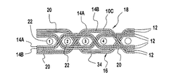
図面について詳細に説明すると、全体を通して、同じ数字は同じ構成要素を示し、図1〜図30は、10A、10B、10C、10D、10Eで示される、本発明による工業用ファブリックの好適な実施形態を示す。工業用ファブリック10A〜10Eは、各々が、他方の上部に一方がある状態で直接的に積層された少なくとも第1及び第2の糸14A、14Bを有する糸アセンブリ12を有する。異なる材質で形成された第1及び第2の糸14A、14Bを用いることにより、上記工業用ファブリックの面16、18は、それぞれ、各ファブリック面16、18の物理的表面特性をカスタマイズできるようにする経済的な方法で別々の素材により大部分を形成することができる。本発明は、様々な工業用製織ファブリックを生産するのに用いることができるが、本発明に従って生産される工業用ファブリック10A〜10Eの好適な用途は、製紙機械のファブリックまたはろ過装置10A〜10Eとしてである。糸アセンブリ12の糸14A、14Bは、他方の上部に一方がある状態で直接的に積層されているように図示及び説明されているが、これは、便宜上のみによるものである。糸14A、14Bは、図示のように他の方法で配列してもよい。
DETAILED DESCRIPTION OF THE DRAWINGS Referring now in detail to the drawings, preferred numerals of the same numbers indicate the same components throughout, and FIGS. Indicates. The
本発明の工業用製織ファブリック10A〜10Eは、平織り法を用いて製造されることが好ましい。しかし、当業者は、ファブリック10A〜10Eを、本発明の範囲を逸脱することなく、エンドレス製織を用いて形成することができることを、本開示から認識するであろう。
The industrial
図1〜図10は、5つの好適な工業用ファブリック10A〜10Eのための製織物を示す。以下、好適な製織物について詳細に説明する。しかし、好適な製織物について説明する前に、本発明のファブリック10A〜10Eの一般的な説明をさらに記載しておく。
1-10 show the fabrics for five preferred
図1、3、5、7、9について説明すると、工業用ファブリック10A〜10Eは、複数のMD糸20と織り合わされた複数のCMD糸22を含む。複数のMD糸20と複数のCMD糸22のうちの一方の少なくとも一部は、実質的にファブリック10A〜10Eの全体にわたって互いに概して接触するように、他方の上部に一方がある状態で直接積層された第1及び第2の糸14A、14Bを有する複数の糸アセンブリ12を備える。図示の好適な実施形態においては、MD糸20の少なくとも一部は、糸アセンブリ12で構成されている。図示はしていないが、CMD糸22の少なくとも一部も、糸アセンブリ12で構成することができる。以下に詳述するように、(図11〜図15及び図27〜図30に示す)継ぎ目端部24に近接するファブリック10A〜10Eの一部は、複数の継ぎ目ループ28を有する継ぎ目領域26を形成する。
1, 3, 5, 7, and 9, the
継ぎ目ループ28を形成するMD糸20のうちのいくつかは、継ぎ目領域26における一対のCMD糸22の間で伸びることができる。従って、当業者は、その間に伸びる横方向の糸によって、第1及び第2の糸14A、14Bを、他方の上部に一方がある状態で直接積層することができるとともに、該糸が、実質的にファブリック10A〜10Eの全体において、互いに概して接触していることをこの開示から認識するであろう。また、当業者は、積層された第1及び第2の糸14A、14Bを分離して、継ぎ目端部24に近接する継ぎ目ループ28(後にさらに説明する)を形成することができるとともに、該糸がなお、実質的にファブリック10A〜10Eの全体において、互いに概して接触していることをこの開示から認識するであろう。
Some of the
MD糸20の少なくとも一部は、一組の糸14A、14Bであってもよい糸アセンブリ12を含むことが好ましい。別法として、CMD糸22の少なくとも一部が糸アセンブリ12を含むことが好ましいが必ずしも必要ではない。図28〜30に示すように、MD糸20の少なくとも一部及びCMD糸22の少なくとも一部は、本発明の範囲を逸脱することなく、糸アセンブリ12を含むことも可能である。
Preferably, at least a portion of the
第1の糸14Aが第1の素材で形成され、かつ第2の糸14Bが、該第1の素材とは異なる第2の素材で形成されていることが好ましいが、必ずしも必要ではない。第1の糸14Aは、好ましくは、必ずしも必要ではないが、糸アセンブリ12の各々において、第2の糸14Bの概して上に配置されている。第1及び第2の糸14A、14Bの間の積層関係は、ファブリック10A〜10Eの上方の面を第1の糸14Aによって概して形成させ、かつファブリック10A〜10Eの下方の面を第2の糸14Bによって概して形成させる。特定の素材からなる糸によって、各ファブリック面16、18を形成することにより、ファブリック10A〜10Eの表面が、異なる物理的表面特性を有することが可能になる。本発明のファブリック10A〜10Eを製紙機械のファブリックに使用する場合、ファブリック10A〜10Eは、上方の製紙側の面18と下方の機械側の面16とを有し、各面は、適切な糸素材及び糸特性を選択することにより、特定の物理的表面特性を有するようにカスタマイズすることができる。
Although it is preferable that the
糸アセンブリ12の第1及び第2の糸14A、14Bは、製織前に、アセンブリとして予め積層しておくことが好ましいが、必ずしも必要ではない。これにより、積層されたMD糸20がヘドルの中を一緒に動くことが可能になるとともに、CMD横糸またはフィラーである糸22が、MD糸20によって形成された杼口に挿入される。別法として、糸アセンブリ12は、共通のへドル内を別々に通し、あるいは、隣接するヘドル内を通して、製織中に積層することができる。
The first and
工業用ファブリック10A〜10Eが、一旦、このようにして形成されると、製紙側の面であってもよいファブリック10A〜10Eの第1の面18は、上記第1の素材に対応する物理的特性を有し、また、上記機械側の面であってもよい、第2の面16は、上記第2の素材に対応する物理的特性を有する。第1及び第2の素材の可能な組み合わせは、それぞれ、ポリフェニレンサルファイド(PPS)と改質ポリシクロヘキサメチレンフタル酸(PCTA)、PPSとポリエチレンテレフタレート(PET)、およびPCTAとPETである。しかし、当業者は、本発明の範囲を逸脱することなく、ファブリック10A〜10Eの機械側の面16及び製紙側の面18に付与すべき所望の物理的特性により、他の素材を選択することができることを本開示から認識するであろう。
Once the
第1の糸14Aは、所望の表面特性をファブリック10A〜10Eの製紙側の面18に与えるように織り込まれることが好ましいが、必ずしも必要ではない。第1の糸14Aは、その上にうねを設けること、その中に溝を設けること、ラフニング、および/またはその上にコーティングを施すことのうちの1つにより織り込むことができる。別法として、機械側の面16は、本発明の範囲を逸脱することなく、同様の織り込んだ糸を組み込むことが可能である。糸14A、14Bは、異なるサイズでもよく、また、上記機械側の面に厚い糸及び薄い糸を交互に配列されるように配列してもよい。このようにして、溝のあるファブリック面を形成することができる。
The
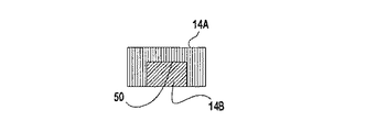
図16〜19及び22について説明すると、本発明のファブリック10A〜10Eは、第1及び第2の糸14A、14Bが、ミスアライメントを阻止するように協働して結合するような相補的な断面形状を有する第1及び第2の糸14A、14Bと一体形成することができる。第1及び第2の糸14A、14Bを結合することにより、ファブリック10A〜10Eは、(その上を浮糸34が通る横方向の糸の数によって判断されるように)他の可能性のある例より長い浮糸34を有することができる。より長い浮糸34を有するファブリック10A〜10Eは、シートに対してより大きな摩耗領域及び接触領域を有するファブリックを形成することができる。
Referring to FIGS. 16-19 and 22,
図16について説明すると、第1の糸14Aは、その中に、第2の糸14Bを収容するための溝50を有する、概して矩形状断面形状を有することが可能である。図17について説明すると、第2の糸14Bは、第1の糸14Aの溝50に係合する突出した半円形部分を有する概して矩形状断面形状を有することが可能である。図18について説明すると、図16の結合糸は、第1の糸14Aと共に、第2の糸14Bを包囲する第3の糸52を含むことができる。図19について説明すると、第2の糸14Bは、第1の糸14Aの対応する形状の溝50と結合される概して台形の突起部を含む。図22について説明すると、第1の糸14Aは、第2の糸14Bをその中に押し込むことができるようにするために、一方の側の中に配置された径方向の間隙32を有する概して環状形状を有する。好適な結合断面糸形状を示したが、当業者は、本発明が、特定の結合断面糸形状に限定されず、不規則な結合糸形状等のどのような糸形状を含んでもよいことを認識するであろう。図28〜30は、CMD糸22として用いられる、相補的な断面結合形状を有する第1及び第2の糸14A、14Bを示すが、当業者は、MD20も、相補的な断面結合形状を有する第1及び第2の糸14A、14Bと一体形成できることを認識するであろう。固い糸アセンブリ12を形成するために結合する、積層された第1及び第2の糸14A、14Bを用いることにより、糸アセンブリ12の少なくとも一部が、少なくとも4つの横方向の糸の上に好ましくは伸びる浮糸34を形成することが可能になる。結合断面形状を有する第1及び第2の糸14A、14Bは、ファブリック10A〜10Eが、より長い露出した浮糸34を有することを可能にするより少ない横方向のずれをうける。
Referring to FIG. 16, the
図20、24について説明すると、本発明のファブリック10A〜10Eは、少なくとも2つの第1の糸14Aの各々が、ファブリック10A〜10Eのほぼ全体にわたって、概して第2の糸14Bと接触するような、第2の糸14Bとの積層関係にある複数の第1の糸14Aを有する糸アセンブリ12を含むことができる。当業者は、少なくとも2つの第2の糸14Bを、単一の第1の糸14Aとの積層関係で配置することができること、および第1の糸14Aが、本発明の範囲を逸脱することなく、ファブリック10A〜10Eの製紙側の面16または機械側の面18のいずれかを形成することができることを、本開示から認識するであろう。
Referring to FIGS. 20 and 24, the
単一の糸14Aまたは14Bを、少なくとも2つの糸14B、14Aと共に積層する場合には、第1の糸14Aが、少なくとも2つの第2の糸14Bを収容するための糸収容面36を形成する、概して矩形状断面形状を有することが好ましいが、必ずしも必要ではない。少なくとも2つの積層された糸14Aまたは14Bを収容するために、少なくとも1つの糸収容溝が、糸収容面36に設けられていることが好ましい。別法として、その上に伸びる少なくとも2つの糸14Aまたは14Bの各々に対して、糸収容面36を形成する該糸と、その上に積層された少なくとも2つの糸との間のミスアライメントを防ぐために、独立した糸収容溝を糸収容面36内に設けることができる。図24に示すように、少なくとも2つの第1の糸14A(または、ファブリック10A〜10Eにより第2の糸14B)は、それぞれ、概して矩形状の断面形状を有することができる。図21に示すように、少なくとも第1及び第2の糸14A、14Bは、各々、第1及び第2の糸14A、14Bが、連続的に隣接して接触している場合に、結果として生じる糸アセンブリが、概して円形断面を有するように、概して半円形断面を有することができる。
When a
本発明のファブリック10A〜10Eは、上記MDまたはCMD方向のいずれかに異なる厚みを有する、積層された第1及び第2の糸14A、14Bを用いて形成することができる。すなわち、ファブリック10A〜10Eは、第1の断面積及び断面形状を有する第1の糸14Aと、該第1の断面積及び断面形状とは異なる第2の断面積及び断面形状を有する第2の糸とで構成することができる。
The
図25について説明すると、ファブリック10A〜10Eは、各々が、第1の糸14Aを第2の糸14Bに結合することができる、複数の相補的な、離間した突出部38を有する第1及び第2の糸14A、14Bを含む、MDまたはCMD糸アセンブリによって形成することができる。
Referring to FIG. 25, the
図9、11〜15及び27について説明すると、MD糸20の少なくとも一部が糸アセンブリ12を含み、かつCMD糸22が、各々が少なくとも2つの離間したCMD糸22を含む、複数の概して積層されたCMD糸の組40として配列されることが好ましい。当業者は、積層され、離間したCMD糸22のそれぞれを、(結合断面形状を有するまたは有しない)2つまたはそれ以上の糸12によって実際に形成することができることを、本開示から認識するであろう。
9, 11-15 and 27, at least a portion of the
2つまたはそれ以上のCMD糸22の層を用いることにより、裏地の製織糸端部(後に詳述する)を、概して、積層されたCMD糸の組40の間で終端することが可能になり、それによって、ファブリック10A〜10Eの製紙側の面18または機械側の面16のいかなる結合も防止する。ファブリック10A〜10Eは、好ましくは、該ファブリックを無端ベルト形状に形成できるようにするために、継ぎ目ループ28を有する少なくとも1つの継ぎ目形成端部24を含む。
The use of two or more layers of
図11〜15について説明すると、継ぎ目ループ28を形成する1つの方法(継ぎ目ループを形成する追加的な方法を、後に詳述する)は、糸アセンブリ12の第1の糸14Aでループ28を形成すると共に、第2の糸14Bが、継ぎ目形成端部24から離れた位置で終端されることである。第1の糸14Aによってループ28が形成された後、第1の糸14Aは、第2の糸14Bが終端されている位置Tに近接した第2の糸経路に沿って、ファブリック10A〜10E内に戻して織られる。第2の糸14Bは、機械側の面16及び製紙側の面18のいずれか一方に近接して終端させることができる。しかし、第2の糸14Bが、概して積層されたCMD糸の組40の間で概して終端されることが好ましい。別法として、ファブリック10A〜10Eの継ぎ目形成端部24に沿った継ぎ目ループ28は、それぞれ、(図30に示すように)糸アセンブリ12の組のうちのひとつによって形成することができる。継ぎ目ループ28を形成するのに用いる戻し織り法により、ファブリック10A〜10Eは、複数の糸アセンブリ12の各々が、対応する第1及び第2の糸14A、14Bの間に織り合わされたいかなる糸からも離れているように形成することができる。
Referring to FIGS. 11-15, one method of forming the seam loop 28 (additional methods of forming the seam loop, described in detail below) is to form the
本発明のファブリック10A〜10Eを広く説明してきたが、(図1〜10に示す)5つの好適なファブリックのための製織を、以下に説明する。以下の実施例のそれぞれにおいては、ファブリック10A〜10Eは、平織りプロセスを用いて製織される。しかし、本発明は、本発明から逸脱することなく、(それぞれその全体を本願明細書に援用する、米国特許出願第60/194,163号明細書及び同第60/259,974号明細書に開示されているような)エンドレス製織またはファブリックアセンブリ法によって実施することができることを理解すべきである。例えば、本発明の原理は、予めクリンプされた糸構成要素を用いて形成されたファブリックにおいて実施することができる。このようなファブリックは、少なくとも一部分、複数の予めクリンプされた重合要素、特に糸、ストリップ等で形成される。クリンプは、形成または結合すべき構成要素に対して、形状及びサイズが概して相補的である特定の大きさに形成されたへこみを形成するように、それらの形成の前に該構成要素に与えられる。該相補的なへこみは、上記糸を、本発明による積層された概して隣接して連続的な接触状態に構成することを可能にする。
Having described
以下に説明する好適なファブリック10A〜10Eは平織りされるので、積層されたMD糸アセンブリ20は、上記横糸を形成し、かつ好ましくは、該MD縦糸アセンブリ20が、所望の杼口形状内に移動できるようにするために、別々にまたは予め積層して、へドルを介して配置される。ファブリック10A〜10Eは、MD縦糸アセンブリ20を適切な杼口形状内に移動させた後、CMD横糸22、または積層された一対のCMD横糸22を該杼口内に挿入することによって形成されることが好ましい。その後、新たに挿入されたCMD糸22を、ファブリック10A〜10Eのすでに製織された部分と密接に係合させてしっかりと当接させるために、オサ打ち棒等が使用される。そして、上記へドルが移動して、次の所望の杼口形状を形成し、別のCMD糸22が該杼口内に挿入される。当業者は、本発明の範囲から逸脱することなく、MD縦糸20を単一の糸で形成することができ、かつCMD横糸22を糸アセンブリ12で形成することができることを、本開示から認識するであろう。
Since the
平織りプロセスを用いた場合、継ぎ目ループ28は、ファブリック10A〜10Eが、一旦、平織りファブリック10A〜10Eを無端ベルト状に形成できるように製織されていると、ファブリック継ぎ目端部24に沿って形成される。継ぎ目ループ28を形成するために、ファブリック10A〜10Eが、最初に製織されると、継ぎ目端部24に近接するファブリック10A〜10Eの一部は製織されない。そして、MD糸20のうちのいくつかは、ファブリック10A〜10E内に再び戻されて織られ、継ぎ目ループ28を形成する。上記平織りファブリックを無端状に接合するために、継ぎ目端部24は、隣接する継ぎ目端部24から継ぎ目ループ28を位置合わせするように配置される。該継ぎ目ループが一旦位置合わせされると、ファブリック10A〜10Eを無端ベルト状に接続するために、ピントル(図示せず)が継ぎ目ループ28に挿入される。継ぎ目ループをファブリック10A〜10E内に形成する様々な方法を、好適な製織の説明の後に記載しておく。
When using a plain weave process, the
(第1の好適な製織)
図1、2について説明すると、第1の好適なファブリック10Aが、6つの杼口製織を用いて形成されている。図1には、12の対になったMD縦糸20−1〜20−12が示されている。図2は、対になったMD縦糸20−1〜20−12に対する、挿入されたCMD横糸22−1〜22−12の位置を示す。具体的には、図2の製織図は、対になったMD縦糸20−1〜20−12が、CMD横糸22−1〜22−12の上かまたは下に位置しているかを示している。該図の空白部は、対応するCMD横糸22が、対応する積層され対になったMD糸20の上を通っていることを示す。例えば、CMD横糸22−1は、積層MD縦糸20−5、20−6、20−9、20−10、20−11及び20−12の上に位置している。図4、6、8、10に示す製織図の各々は、すでに詳述したのと同様に解釈すべきである。
(First preferred weaving)
Referring to FIGS. 1 and 2, a first
第1の好適なファブリック10Aは、CMD横糸22からなる単一の層を用い、以下のように製織される。積層MD縦糸20−1〜20−12は、第1の杼口形態内に移動し、CMD横糸22−1は、積層MD縦糸20−1〜20−4の下、積層MD縦糸20−5及び20−6の上、積層MD縦糸20−7及び20−8の下、および積層MD縦糸20−9〜20−12の上に挿入される。
A first
次いで、積層MD縦糸20−1〜20−12は、第2の杼口形態内に移動する。積層MD縦糸20−1〜20−12が、一旦、第2の杼口形態内に入ると、CMD横糸22−2が、積層MD縦糸20−1及び20−2の下、積層MD縦糸20−3〜20−6の上、積層MD縦糸20−7〜20−10の下、および積層MD縦糸20−11及び20−12の上に挿入される。 Then, the laminated MD warp yarns 20-1 to 20-12 move into the second shed form. Once the laminated MD warp yarns 20-1 to 20-12 enter the second shed form, the CMD weft yarn 22-2 is below the laminated MD warp yarns 20-1 and 20-2, and the laminated MD warp yarn 20- Inserted above 3-20-6, below the laminated MD warp yarns 20-7-20-10, and above the laminated MD warp yarns 20-11 and 20-12.
次いで、積層MD縦糸20−1〜20−12は、第3の杼口形態内に移動する。積層MD縦糸20−1〜20−12が、一旦、第3の杼口形態内に入ると、CMD横糸22−3が、積層MD縦糸20−1及び20−2の下、積層MD縦糸20−3及び20−4の上、積層MD縦糸20−5及び20−6の下、積層MD縦糸20−7及び20−8の上、積層MD縦糸20−9及び20−10の下、および積層MD縦糸20−11及び20−12の上に挿入される。 Next, the laminated MD warp yarns 20-1 to 20-12 move into the third shed form. Once the laminated MD warp yarns 20-1 to 20-12 enter the third shed form, the CMD weft yarn 22-3 is below the laminated MD warp yarns 20-1 and 20-2, and the laminated MD warp yarn 20- 3 and 20-4, laminated MD warp yarns 20-5 and 20-6, laminated MD warp yarns 20-7 and 20-8, laminated MD warp yarns 20-9 and 20-10, and laminated MD It is inserted on the warps 20-11 and 20-12.
次に、積層MD縦糸20−1〜20−12は、第4の杼口形態内に移動する。積層MD縦糸20−1〜20−12が、一旦、第4の杼口形態内に入ると、CMD横糸22−4が、積層MD縦糸20−1〜20−4の上、積層MD縦糸20−5及び20−6の下、積層MD縦糸20−7及び20−8の上、および積層MD縦糸20−9〜20−12の下に挿入される。 Next, the laminated MD warp yarns 20-1 to 20-12 move into the fourth shed form. Once the laminated MD warp yarns 20-1 to 20-12 enter the fourth shed form, the CMD weft yarn 22-4 is above the laminated MD warp yarns 20-1 to 20-4 and the laminated MD warp yarn 20- 5 and 20-6, below the laminated MD warp yarns 20-7 and 20-8, and below the laminated MD warp yarns 20-9 to 20-12.
次いで、積層MD縦糸20−1〜20−12は、第5の杼口形態内に移動する。積層MD縦糸20−1〜20−12が、一旦、第5の杼口形態内に入ると、CMD横糸22−5が、積層MD縦糸20−1及び20−2の上、積層MD縦糸20−3〜20−6の下、積層MD縦糸20−7〜20−10の上、および積層MD縦糸20−11及び20−12の下に挿入される。 Next, the laminated MD warp yarns 20-1 to 20-12 move into the fifth shed form. Once the laminated MD warp yarns 20-1 to 20-12 enter the fifth shed form, the CMD weft yarn 22-5 is placed on the laminated MD warp yarns 20-1 and 20-2, and the laminated MD warp yarn 20- Inserted under 3-20-6, over laminated MD warp yarns 20-7-20-10, and under laminated MD warp yarns 20-11 and 20-12.
そして、積層MD縦糸20−1〜20−12は、第6の杼口形態内に移動する。積層MD縦糸20−1〜20−12が、一旦、第6の杼口形態内に入ると、CMD横糸22−6が、積層MD縦糸20−1及び20−2の上、積層MD縦糸20−3及び20−4の下、積層MD縦糸20−5及び20−6の上、積層MD縦糸20−7及び20−8の下、積層MD縦糸20−9及び20−10の上、および積層MD縦糸20−11及び20−12の下に挿入される。 Then, the laminated MD warp yarns 20-1 to 20-12 move into the sixth shed form. Once the laminated MD warp yarns 20-1 to 20-12 enter the sixth shed form, the CMD weft yarn 22-6 is placed on the laminated MD warp yarns 20-1 and 20-2, and the laminated MD warp yarn 20- Under 3 and 20-4, over laminated MD warp yarns 20-5 and 20-6, under laminated MD warp yarns 20-7 and 20-8, over laminated MD warp yarns 20-9 and 20-10, and laminated MD Inserted under warp yarns 20-11 and 20-12.
上述した製織は、ファブリック10Aの全体にわたって繰り返される。ファブリック10Aが完了した後、継ぎ目端部24に近接する継ぎ目領域26は、好ましくは解かれて再製織され、継ぎ目ループ28を形成し(後に詳述する)、それにより、結果として生じるファブリック10Aが本発明の範囲を逸脱することなく、該製織を継ぎ目領域26内で変化させてもよい。
The weaving described above is repeated throughout the
(第2の好適な製織)
図3、4について説明すると、第2の好適なファブリック10Bが、4つの杼口製織を用いて、および変化する厚さ、例えば、変化する断面積を有するCMD糸22を用いて形成されている。該ファブリックは、以下のように製織される。
(Second preferred weaving)
Referring to FIGS. 3 and 4, a second
積層MD縦糸20−1〜20−8は、第1の杼口形態内に移動する。積層MD縦糸20−1〜20−8が、一旦、第1の杼口形態内に入ると、CMD横糸22−1は、積層MD縦糸20−1及び20−2の下、積層MD縦糸20−3〜20−6の上、および積層MD縦糸20−7及び20−8の下に挿入される。 The laminated MD warps 20-1 to 20-8 move into the first shed form. Once the laminated MD warp yarns 20-1 to 20-8 enter the first shed form, the CMD weft yarn 22-1, under the laminated MD warp yarns 20-1 and 20-2, the laminated MD warp yarn 20- Inserted above 3-20-6 and below the laminated MD warp yarns 20-7 and 20-8.
次に、積層MD縦糸20−1〜20−8が、第2の杼口形態内に移動する。積層MD縦糸20−1〜20−8が、一旦、第2の杼口形態内に入ると、CMD横糸22−2が、積層MD縦糸20−1及び20−2の下、積層MD縦糸20−3及び20−4の上、積層MD縦糸20−5及び20−6の下、および積層MD縦糸20−7及び20−8の上に挿入される。 Next, the laminated MD warp yarns 20-1 to 20-8 move into the second shed form. Once the laminated MD warp yarns 20-1 to 20-8 enter the second shed form, the CMD weft yarn 22-2 is below the laminated MD warp yarns 20-1 and 20-2, and the laminated MD warp yarn 20- 3 and 20-4, below the laminated MD warp yarns 20-5 and 20-6, and above the laminated MD warp yarns 20-7 and 20-8.
次いで、積層MD縦糸20−1〜20−8が、第3の杼口形態内に移動する。積層MD縦糸20−1〜20−8が、一旦、第3の杼口形態内に入ると、CMD横糸22−3が、積層MD縦糸20−1及び20−2の下、積層MD縦糸20−3〜20−6の上、および積層MD縦糸20−7及び20−8の下に挿入される。 Subsequently, the laminated MD warp yarns 20-1 to 20-8 move into the third shed form. Once the laminated MD warp yarns 20-1 to 20-8 enter the third shed form, the CMD weft yarn 22-3 is below the laminated MD warp yarns 20-1 and 20-2, and the laminated MD warp yarn 20- Inserted above 3-20-6 and below the laminated MD warp yarns 20-7 and 20-8.
そして、積層MD縦糸20−1〜20−8が、第4の杼口形態内に移動する。積層MD縦糸20−1〜20−8が、一旦、第4の杼口形態内に入ると、CMD横糸22−4が、積層MD縦糸20−1及び20−2の上、積層MD縦糸20−3及び20−4の下、積層MD縦糸20−5及び20−6の上、および積層MD縦糸20−7及び20−8の下に挿入される。 Then, the laminated MD warp yarns 20-1 to 20-8 move into the fourth shed form. Once the laminated MD warp yarns 20-1 to 20-8 enter the fourth shed form, the CMD weft yarn 22-4 is placed on the laminated MD warp yarns 20-1 and 20-2, and the laminated MD warp yarn 20- 3 and 20-4, laminated MD warp yarns 20-5 and 20-6, and laminated MD warp yarns 20-7 and 20-8.
上述した製織は、ファブリック10Bの全体にわたって繰り返される。ファブリック10Bが完了した後、継ぎ目端部24に近接する継ぎ目領域26は、好ましくは解かれて再製織され、継ぎ目ループ28を形成し、それにより、結果として生じるファブリック10Bが本発明の範囲を逸脱することなく、該製織を継ぎ目領域26内で変化させてもよい。
The weaving described above is repeated throughout the
(第3の好適な製織)
図5、6について説明すると、第3の好適なファブリック10Cが、4つの杼口製織を用いて、以下のように形成される。積層MD縦糸20−1〜20−8は、第1の杼口形態内に移動し、CMD横糸22−1は、積層MD縦糸20−1及び20−2の上、積層MD縦糸20−3及び20−4の下、積層MD縦糸20−5及び20−6の上、および積層MD縦糸20−7及び20−8の下に挿入される。
(Third preferred weaving)
Referring to FIGS. 5 and 6, a third preferred fabric 10C is formed using four shed weaves as follows. The laminated MD warp yarns 20-1 to 20-8 move into the first shed form, and the CMD weft yarn 22-1, on the laminated MD warp yarns 20-1 and 20-2, the laminated MD warp yarn 20-3 and It is inserted below the laminated MD warp yarns 20-5 and 20-6, and below the laminated MD warp yarns 20-7 and 20-8.
次に、積層MD縦糸20−1〜20−8が、第2の杼口形態内に移動する。積層MD縦糸20−1〜20−8が、一旦、第2の杼口形態内に入ると、CMD横糸22−2が、積層MD縦糸20−1及び20−2の下、積層MD縦糸20−3〜20−6の上、および積層MD縦糸20−7及び20−8の下に挿入される。 Next, the laminated MD warp yarns 20-1 to 20-8 move into the second shed form. Once the laminated MD warp yarns 20-1 to 20-8 enter the second shed form, the CMD weft yarn 22-2 is below the laminated MD warp yarns 20-1 and 20-2, and the laminated MD warp yarn 20- Inserted above 3-20-6 and below the laminated MD warp yarns 20-7 and 20-8.
次いで、積層MD縦糸20−1〜20−8が、第3の杼口形態内に移動する。積層MD縦糸20−1〜20−8が、一旦、第3の杼口形態内に入ると、CMD横糸22−3が、積層MD縦糸20−1及び20−2の下、積層MD縦糸20−3及び20−4の上、積層MD縦糸20−5及び20−6の下、および積層MD縦糸20−7及び20−8の上に挿入される。 Subsequently, the laminated MD warp yarns 20-1 to 20-8 move into the third shed form. Once the laminated MD warp yarns 20-1 to 20-8 enter the third shed form, the CMD weft yarn 22-3 is below the laminated MD warp yarns 20-1 and 20-2, and the laminated MD warp yarn 20- 3 and 20-4, below the laminated MD warp yarns 20-5 and 20-6, and above the laminated MD warp yarns 20-7 and 20-8.
そして、積層MD縦糸20−1〜20−8が、第4の杼口形態内に移動する。積層MD縦糸20−1〜20−8が、一旦、第4の杼口形態内に入ると、CMD横糸22−4が、積層MD縦糸20−1及び20−2の上、積層MD縦糸20−3〜20−6の下、および積層MD縦糸20−7及び20−8の上に挿入される。 Then, the laminated MD warp yarns 20-1 to 20-8 move into the fourth shed form. Once the laminated MD warp yarns 20-1 to 20-8 enter the fourth shed form, the CMD weft yarn 22-4 is placed on the laminated MD warp yarns 20-1 and 20-2, and the laminated MD warp yarn 20- Inserted under 3-20-6 and above the laminated MD warps 20-7 and 20-8.
上述した製織は、ファブリック10Cの全体にわたって繰り返される。ファブリック10Cが完了した後、継ぎ目端部24に近接する継ぎ目領域26は、好ましくは解かれて再製織され、継ぎ目ループ28を形成し、それにより、結果として生じるファブリック10Cが本発明の範囲を逸脱することなく、該製織を継ぎ目領域26内で変化させてもよい。
The weaving described above is repeated throughout the fabric 10C. After the fabric 10C is completed, the
(第4の好適な製織)
図7、8について説明すると、第4の好適なファブリック10Dは、好ましくは、垂直方向にずれている二重層のCMD糸を有する、8つの杼口製織である。ファブリック10Dは、以下のように製織される。
(Fourth preferred weaving)
Referring to FIGS. 7 and 8, the fourth preferred fabric 10D is preferably eight shed weaves with double layers of CMD yarns that are vertically offset. The fabric 10D is woven as follows.
積層MD縦糸20−1〜20−8は、第1の杼口形態内に移動する。積層MD縦糸20−1〜20−8が、一旦、第1の杼口形態内に入ると、CMD横糸22−1は、積層MD縦糸20−1〜20−4の下、積層MD縦糸20−5及び20−6の上、および積層MD縦糸20−7及び20−8の下に挿入される。 The laminated MD warps 20-1 to 20-8 move into the first shed form. Once the laminated MD warp yarns 20-1 to 20-8 enter the first shed form, the CMD weft yarn 22-1 is below the laminated MD warp yarns 20-1 to 20-4, and the laminated MD warp yarn 20- 5 and 20-6 and below the laminated MD warp yarns 20-7 and 20-8.
次に、積層MD縦糸20−1〜20−8が、第2の杼口形態内に移動する。積層MD縦糸20−1〜20−8が、一旦、第2の杼口形態内に入ると、CMD横糸22−2が、積層MD縦糸20−1〜20−4の下、および積層MD縦糸20−5〜20−8の上に挿入される。
Next, the laminated MD warp yarns 20-1 to 20-8 move into the second shed form. Once the laminated MD warp yarns 20-1 to 20-8 enter the second shed form, the CMD weft yarn 22-2 is below the laminated MD warp yarns 20-1 to 20-4 and the laminated
次いで、積層MD縦糸20−1〜20−8が、第3の杼口形態内に移動する。積層MD縦糸20−1〜20−8が、一旦、第3の杼口形態内に入ると、CMD横糸22−3が、積層MD縦糸20−1〜20−6の下、および積層MD縦糸20−7及び20−8の上に挿入される。
Subsequently, the laminated MD warp yarns 20-1 to 20-8 move into the third shed form. Once the laminated MD warp yarns 20-1 to 20-8 enter the third shed form, the CMD weft yarn 22-3 is below the laminated MD warp yarns 20-1 to 20-6 and the laminated
次に、積層MD縦糸20−1〜20−8が、第4の杼口形態内に移動する。積層MD縦糸20−1〜20−8が、一旦、第4の杼口形態内に入ると、CMD横糸22−4が、積層MD縦糸20−1及び20−2の下、積層MD縦糸20−3及び20−4の上、積層MD縦糸20−5及び20−6の下、および積層MD縦糸20−7及び20−8の上に挿入される。 Next, the laminated MD warp yarns 20-1 to 20-8 move into the fourth shed form. Once the laminated MD warp yarns 20-1 to 20-8 enter the fourth shed form, the CMD weft yarn 22-4 is below the laminated MD warp yarns 20-1 and 20-2, and the laminated MD warp yarn 20- 3 and 20-4, below the laminated MD warp yarns 20-5 and 20-6, and above the laminated MD warp yarns 20-7 and 20-8.
次いで、積層MD縦糸20−1〜20−8が、第5の杼口形態内に移動する。積層MD縦糸20−1〜20−8が、一旦、第5の杼口形態内に入ると、CMD横糸22−5が、積層MD縦糸20−1及び20−2の下、積層MD縦糸20−3及び20−4の上、および積層MD縦糸20−5〜20−8の下に挿入される。 Then, the laminated MD warp yarns 20-1 to 20-8 move into the fifth shed form. Once the laminated MD warp yarns 20-1 to 20-8 enter the fifth shed form, the CMD weft yarn 22-5 is below the laminated MD warp yarns 20-1 and 20-2, and the laminated MD warp yarn 20- 3 and 20-4, and below the laminated MD warp yarns 20-5 to 20-8.
次に、積層MD縦糸20−1〜20−8が、第6の杼口形態内に移動する。積層MD縦糸20−1〜20−8が、一旦、第6の杼口形態内に入ると、CMD横糸22−6が、積層MD縦糸20−1〜20−4の上、および積層MD縦糸20−5〜20−8の下に挿入される。 Next, the laminated MD warp yarns 20-1 to 20-8 move into the sixth shed form. Once the laminated MD warps 20-1 to 20-8 enter the sixth shed form, the CMD weft 22-6 is above the laminated MD warps 20-1 to 20-4 and the laminated MD warps 20 Inserted under -5 to 20-8.
次いで、積層MD縦糸20−1〜20−8が、第7の杼口形態内に移動する。積層MD縦糸20−1〜20−8が、一旦、第7の杼口形態内に入ると、CMD横糸22−7が、積層MD縦糸20−1及び20−2の上、および積層MD縦糸20−3〜20−8の下に挿入される。
Subsequently, the laminated MD warp yarns 20-1 to 20-8 move into the seventh shed form. Once the laminated MD warp yarns 20-1 to 20-8 enter the seventh shed form, the CMD weft yarn 22-7 is above the laminated MD warp yarns 20-1 and 20-2 and the laminated
そして、積層MD縦糸20−1〜20−8が、第8の杼口形態内に移動する。積層MD縦糸20−1〜20−8が、一旦、第8の杼口形態内に入ると、CMD横糸22−8が、積層MD縦糸20−1及び20−2の上、積層MD縦糸20−3及び20−4の下、積層MD縦糸20−5及び20−6の上、および積層MD縦糸20−7及び20−8の下に挿入される。 Then, the laminated MD warp yarns 20-1 to 20-8 move into the eighth shed form. Once the laminated MD warp yarns 20-1 to 20-8 enter the eighth hook form, the CMD weft yarn 22-8 is placed on the laminated MD warp yarns 20-1 and 20-2, and the laminated MD warp yarn 20- 3 and 20-4, laminated MD warp yarns 20-5 and 20-6, and laminated MD warp yarns 20-7 and 20-8.
上述した製織は、ファブリック10Dの全体にわたって繰り返される。ファブリック10Dが完了した後、継ぎ目端部24に近接する継ぎ目領域26は、好ましくは解かれて再製織され、継ぎ目ループ28を形成し、それにより、結果として生じるファブリック10Dが本発明の範囲を逸脱することなく、該製織を継ぎ目領域26内で変化させてもよい。
The weaving described above is repeated throughout the fabric 10D. After the fabric 10D is complete, the
(第5の好適な製織)
図9、10について説明すると、第5の好適なファブリック10Eは、8つの杼口製織を用いて形成され、好ましくは、垂直方向に位置合わせされている二重層のCMD糸を用いる。ファブリック10Eは、以下のように製織される。
(Fifth preferred weaving)
Referring to FIGS. 9 and 10, a fifth
積層MD縦糸20−1〜20−8は、第1の杼口形態内に移動する。積層MD縦糸20−1〜20−8が、一旦、第1の杼口形態内に入ると、CMD横糸22−1は、積層MD縦糸20−1及び20−2の上、積層MD縦糸20−3及び20−4の下、および積層MD縦糸20−5〜20−8の上に挿入される。 The laminated MD warps 20-1 to 20-8 move into the first shed form. Once the laminated MD warp yarns 20-1 to 20-8 enter the first shed form, the CMD weft yarn 22-1, the laminated MD warp yarns 20-1 and 20-2, the laminated MD warp yarn 20- 3 and 20-4 and above the laminated MD warp yarns 20-5 to 20-8.
次に、積層MD縦糸20−1〜20−8が、第2の杼口形態内に移動する。積層MD縦糸20−1〜20−8が、一旦、第2の杼口形態内に入ると、CMD横糸22−2が、積層MD縦糸20−1及び20−2の上、および積層MD縦糸20−3〜20−8の下に挿入される。
Next, the laminated MD warp yarns 20-1 to 20-8 move into the second shed form. Once the laminated MD warp yarns 20-1 to 20-8 enter the second shed form, the CMD weft yarn 22-2 is above the laminated MD warp yarns 20-1 and 20-2 and the laminated
次いで、積層MD縦糸20−1〜20−8が、第3の杼口形態内に移動する。積層MD縦糸20−1〜20−8が、一旦、第3の杼口形態内に入ると、CMD横糸22−3が、積層MD縦糸20−1〜20−6の上、および積層MD縦糸20−7及び20−8の下に挿入される。
Subsequently, the laminated MD warp yarns 20-1 to 20-8 move into the third shed form. Once the laminated MD warp yarns 20-1 to 20-8 enter the third shed form, the CMD weft yarn 22-3 is above the laminated MD warp yarns 20-1 to 20-6 and the laminated
次に、積層MD縦糸20−1〜20−8が、第4の杼口形態内に移動する。積層MD縦糸20−1〜20−8が、一旦、第4の杼口形態内に入ると、CMD横糸22−4が、積層MD縦糸20−1〜20−4の下、積層MD縦糸20−5及び20−6の上、および積層MD縦糸20−7及び20−8の下に挿入される。 Next, the laminated MD warp yarns 20-1 to 20-8 move into the fourth shed form. Once the laminated MD warp yarns 20-1 to 20-8 enter the fourth shed form, the CMD weft yarn 22-4 is below the laminated MD warp yarns 20-1 to 20-4, and the laminated MD warp yarn 20- 5 and 20-6 and below the laminated MD warp yarns 20-7 and 20-8.
次いで、積層MD縦糸20−1〜20−8が、第5の杼口形態内に移動する。積層MD縦糸20−1〜20−8が、一旦、第5の杼口形態内に入ると、CMD横糸22−5が、積層MD縦糸20−1及び20−2の下、および積層MD縦糸20−3〜20−8の上に挿入される。
Then, the laminated MD warp yarns 20-1 to 20-8 move into the fifth shed form. Once the laminated MD warp yarns 20-1 to 20-8 enter the fifth shed form, the CMD weft yarn 22-5 is below the laminated MD warp yarns 20-1 and 20-2 and the laminated
次に、積層MD縦糸20−1〜20−8が、第6の杼口形態内に移動する。積層MD縦糸20−1〜20−8が、一旦、第6の杼口形態内に入ると、CMD横糸22−6が、積層MD縦糸20−1及び20−2の下、積層MD縦糸20−3及び20−4の上、および積層MD縦糸20−5〜20−8の下に挿入される。 Next, the laminated MD warp yarns 20-1 to 20-8 move into the sixth shed form. Once the laminated MD warp yarns 20-1 to 20-8 enter the sixth shed form, the CMD weft yarn 22-6 is below the laminated MD warp yarns 20-1 and 20-2, and the laminated MD warp yarn 20- 3 and 20-4, and below the laminated MD warp yarns 20-5 to 20-8.
次いで、積層MD縦糸20−1〜20−8が、第7の杼口形態内に移動する。積層MD縦糸20−1〜20−8が、一旦、第7の杼口形態内に入ると、CMD横糸22−7が、積層MD縦糸20−1〜20−4の上、積層MD縦糸20−5及び20−6の下、および積層MD縦糸20−7及び20−8の上に挿入される。 Subsequently, the laminated MD warp yarns 20-1 to 20-8 move into the seventh shed form. Once the laminated MD warp yarns 20-1 to 20-8 enter the seventh shed form, the CMD weft yarn 22-7 is above the laminated MD warp yarns 20-1 to 20-4 and the laminated MD warp yarn 20- 5 and 20-6 and above the laminated MD warp yarns 20-7 and 20-8.
そして、積層MD縦糸20−1〜20−8が、第8の杼口形態内に移動する。積層MD縦糸20−1〜20−8が、一旦、第8の杼口形態内に入ると、CMD横糸22−8が、積層MD縦糸20−1〜20−6の下、および積層MD縦糸20−7及び20−8の上に挿入される。
Then, the laminated MD warp yarns 20-1 to 20-8 move into the eighth shed form. Once the laminated MD warp yarns 20-1 to 20-8 enter the eighth hook form, the CMD weft yarn 22-8 is below the laminated MD warp yarns 20-1 to 20-6 and the laminated
上述した製織は、ファブリック10Eの全体にわたって繰り返される。ファブリック10Eが完了した後、継ぎ目端部24に近接する継ぎ目領域26は、好ましくは解かれて再製織され、継ぎ目ループ28を形成し、それにより、結果として生じるファブリック10Eが本発明の範囲を逸脱することなく、該製織を継ぎ目領域26内で変化させてもよい。
The weaving described above is repeated throughout the
上述した5つの好適な製織に係る5つのファブリック製織の特性を、実験用ファブリックのために以下に一覧表に記載する。実験用データは、上記好適な製織の各々に対して複数のファブリックを製織し、かつ優れた物理的特性を呈しただけでなく、向上した継ぎ目性及び製織効率も有していたファブリックを選ぶことにより選択した。 The properties of the five fabric weaving according to the five preferred weaving described above are listed below for the experimental fabric. The experimental data is to select a fabric that weaves multiple fabrics for each of the preferred weaves and not only exhibits excellent physical properties, but also has improved seam and weaving efficiency. Selected by.
表1:実験的に決めたファブリック特性
好適な製織番号
図面の番号
1及び2、3及び4、5及び6、7及び8、9及び10
縦糸サイズ
横糸サイズ
ファブリックのメッシュ(縦糸×横糸)
通気度
紙の厚さ
シート密着率(%)
弾性率
引っ張り強度
上記ファブリックの特性は、以下のように算出した。通気度測定は、メリーランド州ゲイサーズバーグのフレイジャー・プレシジョン・インストルメント・カンパニーから入手可能な高圧示差通気度装置を使用して、上記ファブリックの全体に127Paの圧力差で、米国材料試験協会のASTM D737−96規格に従って、ヒートセットファブリックサンプルに対して行った。
Table 1: Experimentally determined fabric properties Suitable weaving
Warp size weft size fabric mesh (warp x weft)
Permeability paper thickness sheet adhesion rate (%)
Elastic modulus tensile strength
The characteristics of the fabric were calculated as follows. Air permeability measurements were made using a high pressure differential air permeability device available from Fraser Precision Instrument Company, Gaithersburg, Maryland, with a pressure differential of 127 Pa across the fabric, and the American Society for Testing Materials. In accordance with ASTM D737-96 standard.
シート密着率は、次のようにして測定した。ペンシルベニア州クラークスサミットのベロイト社マンハッタン事業部より入手可能なベロイト・ニップ・インプレッション・ペーパーのストリップからのインクを、熱及び圧力によって、ドライヤーファブリックサンプルの表面に転写する。次いで、該インクを、該ドライヤーファブリックの表面から一枚のコピー紙に転写する。該インプレッションは、スキャンされてディジタル画像が生成され、該画像から接触面積がコンピュータプログラムを用いて計算される。 The sheet adhesion rate was measured as follows. Ink from a strip of Beloit Nip Impression Paper, available from Beloit Manhattan Division of Clarks Summit, Pennsylvania, is transferred to the surface of a dryer fabric sample by heat and pressure. The ink is then transferred from the surface of the dryer fabric onto a sheet of copy paper. The impression is scanned to produce a digital image, from which the contact area is calculated using a computer program.
弾性率は、一定に増加する負荷の下で、機械方向に向けられているファブリックサンプルを、マサチューセッツ州カントンのインストロン社から入手可能な、インストロン 1122型 引っ張り試験機等の定速伸長(CRE;Constant Rate of Extension)試験機内に配置することによって測定した。上記弾性率は、弛みが取り除かれた後に、上記ファブリックの応力歪み曲線の初期の傾斜から測定する。該試験は、機械方向の負荷を受けているときの該ファブリックの引っ張り抵抗の尺度を与え、それは、製紙機械上での長期安定性の示度を示す。 The modulus of elasticity is a constant speed extension (CRE) such as an Instron 1122 tensile tester, available from Instron, Canton, Massachusetts, with fabric samples oriented in the machine direction under a constantly increasing load. ; Constant Rate of Extension) by placing in a tester. The elastic modulus is measured from the initial slope of the fabric stress-strain curve after the slack has been removed. The test provides a measure of the fabric's tensile resistance when subjected to machine direction loading, which indicates an indication of long-term stability on the papermaking machine.
引っ張り強度は、マサチューセッツ州カントンのインストロン社から入手可能な、インストロン 1122型 引っ張り試験機等のCRE(Constant Rate of Extension)試験機を使用して、ファブリックサンプルを、突発故障に至るまで引っ張り負荷の下に置くことによって測定した。この試験は、ファブリックの応力歪み特性の尺度を与える
図16〜24について説明すると、上述したように、説明した好適なファブリック10A〜10Eは、それぞれ、相補的な結合断面領域を有していてもよい第1及び第2の糸14A、14Bによって形成されている、あるいは、それぞれ、複数のより小さな糸を、比較的大きな糸の糸収容面上に概して位置合わせした状態の1つの比較的大きな糸を含む、縦糸および/または横糸によって製造することができる。しかし、表1に記載した実験用ファブリックは、全て、2つの平織り縦糸を糸アセンブリとして用いて製造した。
Tensile strength is measured using a CRE (Constant Rate of Extension) tester such as Instron 1122 tensile tester available from Instron, Canton, Massachusetts. Measured by placing under. This test gives a measure of the stress-strain properties of the fabric. Referring to FIGS. 16-24, as described above, the
工業用ファブリック10A〜10Eを形成するのに用いる特定の製織パターンにかかわらず、必要な継ぎ目ループ28を継ぎ目端部24に沿って形成して、平織りファブリック10A〜10Eを無端ファブリックベルトに形成するために、様々な方法を用いることができる。一般に、平織りファブリックは、概して継ぎ目領域26の全体を通して、部分的に解かれる。そして、該解かれた糸のうちのいくつかは、継ぎ目ループに形成される。その後、継ぎ目ループ形成糸の端部、および残っている解かれた糸は、再び製織される。この解くプロセス及び再製織するプロセスは、手または機械によって実行することができる。以下に、再製織プロセス中に、継ぎ目ループを形成するいくつかの方法を詳述する。各方法は、一組のMD糸54が、どのように配置されて継ぎ目ループ28を形成するかを説明することにより議論する。以下に説明する方法は、本発明から逸脱することなく、十分な数の継ぎ目ループ28を形成するために、単一のファブリック端部24に沿って、多数の組のMD糸54に対して繰り返すことができることを理解されたい。
Regardless of the particular weaving pattern used to form the
図11に、継ぎ目ループ28を形成する第1の好適な方法を示す。MD糸の組54を用いて継ぎ目ループ28を形成するために、第1の積層MD糸14Aは、上記解くプロセス中に、(継ぎ目領域26の)部分“T”で終端される。次いで、第2の糸14Bが、継ぎ目ループ28を形成するように配置され、終端された第1のMD糸14Aの経路の残りの部分に沿って再製織される。第2の糸14Bが、一旦、位置“T”に戻されて織られると、該糸は切断される。これにより、好ましくは、ファブリック10A〜10Eの残りの部分と等しい製織を有する継ぎ目領域26が形成される。当業者は、糸が取り付けられ、または切断されて、織り合わされることにより定位置に保持される上記ファブリックの位置を、(本発明の継ぎ目ループ形成方法のうちのいずれかの場合に)製紙側の面16、機械側の面18に近接させることができ、あるいは、本発明の範囲を逸脱することなく、ファブリック10A〜10E内に配置することができることを、本開示から認識するであろう。
FIG. 11 illustrates a first preferred method of forming the
図12に、継ぎ目ループ28を形成する第2の好適な方法を示す。MD糸の組54を用いて継ぎ目ループ28を形成するために、第2の積層MD糸14Bは、上記解くプロセス中に、(継ぎ目領域26の)部分“T”で終端される。次いで、第1の糸14Aが、継ぎ目ループ28を形成するように配置され、終端された第2のMD糸14Bの経路の残りの部分に沿って再製織される。第1の糸14Aが、一旦、位置“T”に戻されて織られると、該糸は切断される。
FIG. 12 illustrates a second preferred method of forming the
図13に、継ぎ目ループ28を形成する第3の好適な方法を示す。継ぎ目ループ28は、MD糸の組54、56の間に形成される。まず、積層MD糸の組54の第2の積層MD糸14Bが、位置“Y”の近傍で終端され、隣接するMD糸の組56の第1の積層MD糸16Aが、上記再製織プロセス中に、部分“T”で終端される。次いで、第1の積層MD糸14Aが、継ぎ目ループ28を形成するように配置されて、隣接するMD糸の組56の終端されたMD糸16Aの残りの経路に沿って、部分“T”に近い位置まで再製織される。好ましくは、第1の積層MD糸14Aの再製織部分は、単に、ファブリック10A〜10Eへのその織り合わせによって保持される。上記再製織プロセス中に、隣接する糸の組56の第2の積層MD糸16Bは、終端されたMD糸16Aの残りの経路に沿って再製織される。
FIG. 13 shows a third preferred method of forming the
図14に、継ぎ目ループ28を形成する第4の好適な方法を示す。MD糸の組54を用いて継ぎ目ループ28を形成するために、上記再製織プロセスにおいて、隣接するMD糸の組56の第2の積層MD糸16Bは、位置“Z”の近くで終端され、MD糸の組56の第1の積層MD糸16Aは、位置“T”の近くで終端される。次いで、第1及び第2の積層MD糸14A、14Bは、積層された継ぎ目ループ28を形成するように、およびMD糸の組56の第2及び第1の積層MD糸16B、16Aの残りの経路をそれぞれたどるように配置される。再製織された第2の積層MD糸16Bは、位置“T”に近い位置まで再製織されて、好ましくは、そこで切断される。再製織された第1の積層MD糸14Aは、位置“Z”の近くの隣接するMD糸の組56の終端された第2の積層MD糸16Bの残りの経路に沿って伸びる。第1及び第2の積層MD糸14A、14Bは、の再製織端部は、好ましくは、単に織り合わせることによって定位置に保持される。該終端部分は、好ましくは、向上した継ぎ目ループ強度を実現できるように交互に配列される。
FIG. 14 shows a fourth preferred method of forming the
図15に、継ぎ目ループ28を形成する第5の好適な方法を示す。MD糸の組54を用いて継ぎ目ループ28を形成するために、上記再製織プロセスにおいて、隣接するMD糸の組56の第1及び第2の積層MD糸16A、16Bは、位置“T”の近くで終端される。該再製織プロセス中、第1及び第2の積層MD糸14A、14Bは、2つの糸14A、14Bからなる継ぎ目ループ28を形成するように配置されて、隣接するMD糸の組56の終端された第1及び第2の積層MD糸16A、16Bの残りの経路に沿って、位置“T”に近い位置まで再製織される。第1及び第2の積層MD糸14A、14Bは、単に織り合わせることによって定位置に保持されることが好ましい。
FIG. 15 shows a fifth preferred method of forming the
図26について説明すると、ファブリック10A〜10Eにおいて、3つまたはそれ以上の層のCMD横糸22−1〜22−6を有することが可能である。また、個々のCMD横糸22−1〜22−6の各々は、本発明の範囲を逸脱することなく、相補的な結合断面形状を有する一組の糸からなる糸アセンブリ12として形成することができる。
Referring to FIG. 26,
図27は、本発明による、代替的な継ぎ目構成を示す。継ぎ目領域26は、図12に示したのと同じ方法で形成された継ぎ目ループ28を有する。図に示すように、継ぎ目ループ28は、好ましくは、ファブリック10A〜10Eの対向する端部を一緒に接続することができると共に、継ぎ目24の両端に位置合わせされた上記MD糸アセンブリを保持するように、他のMD糸アセンブリごとに形成される。
FIG. 27 illustrates an alternate seam configuration in accordance with the present invention. The
図28〜30について説明すると、CMD糸22は、相補的な結合断面を有する第1及び第2の糸によって形成することができる。図28において、第1の積層MD糸14Aは、第2の積層MD糸14Bの経路に沿って、ファブリック10A〜10E内に戻して織られ、第2の積層MD糸14Bの端部の近くの部分“T”で終端される。すなわち、継ぎ目ループ28は、第1の積層MD糸14Aをファブリック10A〜10E内に戻して織ることによって定位置に保持される。
Referring to FIGS. 28-30, the
図29、30は、CMD横糸アセンブリ22を形成する上記第1及び第2の積層CMD糸の間に、戻して織られる積層MD糸を配置させることによって、戻した織られる積層MD糸をファブリック10A〜10E内に固定する方法を示す。該ファブリックが緊張状態にある場合、これは、CMD糸アセンブリ22を形成する第1及び第2の積層糸の間に圧力を生成し、それによって、戻して織られる積層MD糸20を、継ぎ目領域26内の定位置に固定するという所望の効果を有する。
FIGS. 29 and 30 show that the back woven LAMD can be returned to the
図29について説明すると、第2の積層MD糸14Bは、第1の積層MD糸14Aの経路の残りに沿って部分“T”に近い位置まで、ファブリック10A〜10E内に戻して織られる。戻して織られた第2の積層MD糸14B及び第1の積層MD糸14Aは、積層されたCMD横糸の組の積層糸17A、17Bの間に伸びる。
Referring to FIG. 29, the second
図30について説明すると、継ぎ目ループ28は、上記再製織プロセス中に、隣接するMD糸アセンブリ56の第1の積層MD糸16Aを部分“Z”の近傍で終端することにより、および隣接するMD糸アセンブリ56の第2の積層MD糸16Bを部分“T”の近傍で終端することにより、MD糸アセンブリ54を用いて形成される。そして、糸アセンブリ54を含む第1及び第2の積層MD糸14A、14Bは、積層継ぎ目ループ28を形成するように配置される。第1の積層MD糸14Aは、隣接するMD糸アセンブリ56の第2の糸16Bの経路の残りに沿って、位置“T”に近い位置まで戻って織られる。糸14A、16Bの端部は、それぞれ、対向する糸17A、17Bによって形成された積層CMD糸アセンブリ22の間を通る。第2の積層MD糸14Bは、隣接するMD糸アセンブリ56の第1の積層糸16Bの経路の残りに沿って、位置“Z”に近い位置まで戻って織られる。第2の糸14B及び第1の糸16Aの端部は、対向する糸17A、17Bによって形成された積層CMD糸アセンブリ22の間を通る。
Referring to FIG. 30, the
再製織時に、上記MD糸を単に固定するために、および高強度の継ぎ目ループを形成するために、CMD糸アセンブリを上記継ぎ目領域で用いることも可能である。この種の継ぎ目構造においては、形成された継ぎ目の各面に5つより少ないCMD糸の一部が、図25及び28〜30に示すようなCMD糸アセンブリと置換される。継ぎ目ループ28の形成に続くMD糸14の再製織中、該MD糸は、CMD糸アセンブリ22の構成要素糸の間にたくし込まれる。そして、上記ファブリックは、緊張されて熱処理され、該CMD糸アセンブリを結合させて該MD糸を定位置に確実に固定させる。
It is also possible to use a CMD yarn assembly in the seam area to simply secure the MD yarn during reweaving and to form a high strength seam loop. In this type of seam structure, a portion of less than 5 CMD yarns on each side of the formed seam is replaced with a CMD yarn assembly as shown in FIGS. 25 and 28-30. During the reweaving of the MD yarn 14 following the formation of the
上述したように、本発明のファブリック10A〜10Eは、どのような所望の製紙機械の要求にも応じるように容易にカスタマイズすることができる。異なる糸素材、サイズ及び形状を、上記糸アセンブリに組み込む能力は、ファブリック構造を非常に柔軟にする。ファブリック10A〜10Eは、非常に丈夫で安定している。ファブリックの表面特性は、シートリリースまたは他の品質を向上させるように、質感を出したまたは表面処理した糸を用いることによってカスタマイズすることができる。高強度で低断面の継ぎ目ループはたいていのデザインで形成することができ、すなわち、該継ぎ目は、同様の従来のデザインよりも構成及び形成するのが容易である。このことは、織る人が、1つ、2つまたは3つの横糸素材の間丁を用いることができ、かつ次のファブリックの要求を満たすように該横糸素材を入れ替えることができる製織プロセスにおいて、2つまたはそれ以上の糸を結合することによって実現される。一種類以上の横糸を同じ巻糸軸架に巻き付けることができ、また所望の縦糸を、織物内に容易に導くことができる。
As mentioned above, the
当業者は、広い本発明のコンセプトから逸脱することなく、本発明の上述した実施形態に対して変更が可能であることを認識されたい。従って、本発明が、上述した特定の実施形態に限定されず、添付クレームにより定義したような本発明の主旨及び範囲内にある全ての変更例を包含しようとするものであることを理解されたい。 Those skilled in the art will recognize that modifications can be made to the above-described embodiments of the invention without departing from the broad inventive concept. Accordingly, it is to be understood that the invention is not limited to the specific embodiments described above, but is intended to cover all modifications that are within the spirit and scope of the invention as defined by the appended claims. .
Claims (24)
a)前記複数の縦糸の少なくとも一部が、複数の糸アセンブリを含み、
b)前記複数の糸アセンブリの各々が、少なくとも第1及び第2の糸で構成されており、
c)前記第1及び第2の糸が、ファブリック面に対してほぼ垂直方向に重ねられ、かつ実質的に前記ファブリックの全体にわたって、互いに概して連続かつ隣接して接触するように、前記製織されたファブリック内に配列されている、製織された工業用ファブリック。A woven industrial fabric comprising a plurality of warps interwoven with a plurality of wefts,
a) at least a portion of said plurality of warp yarns comprises a plurality of yarn assemblies,
b) each of the plurality of yarn assemblies is composed of at least first and second yarns;
c) the first and second yarns are woven so that they are superimposed substantially perpendicular to the fabric surface and are generally continuous and adjacent to each other substantially throughout the fabric; Woven industrial fabric arranged in a fabric.
Applications Claiming Priority (2)
| Application Number | Priority Date | Filing Date | Title |
|---|---|---|---|
| US30327301P | 2001-07-05 | 2001-07-05 | |
| PCT/US2002/021005 WO2003004736A2 (en) | 2001-07-05 | 2002-07-03 | Industrial fabric including yarn assemblies |
Publications (2)
| Publication Number | Publication Date |
|---|---|
| JP2004534159A JP2004534159A (en) | 2004-11-11 |
| JP4261341B2 true JP4261341B2 (en) | 2009-04-30 |
Family
ID=23171301
Family Applications (1)
| Application Number | Title | Priority Date | Filing Date |
|---|---|---|---|
| JP2003510488A Expired - Fee Related JP4261341B2 (en) | 2001-07-05 | 2002-07-03 | Industrial fabric including yarn assembly |
Country Status (9)
| Country | Link |
|---|---|
| US (1) | US7121306B2 (en) |
| EP (1) | EP1412572B1 (en) |
| JP (1) | JP4261341B2 (en) |
| CN (1) | CN100357508C (en) |
| AT (1) | ATE372404T1 (en) |
| AU (1) | AU2002316520A1 (en) |
| CA (1) | CA2451370C (en) |
| DE (1) | DE60222267T2 (en) |
| WO (1) | WO2003004736A2 (en) |
Families Citing this family (28)
| Publication number | Priority date | Publication date | Assignee | Title |
|---|---|---|---|---|
| KR100439560B1 (en) * | 2002-04-22 | 2004-07-12 | 기영상 | Process for preparing high-strength pe tarpaulin |
| GB0224989D0 (en) | 2002-10-28 | 2002-12-04 | Waterleaf Ltd | System and method for jackpot wagering |
| US20040127127A1 (en) * | 2002-12-30 | 2004-07-01 | Dana Eagles | Bicomponent monofilament |
| US20040127129A1 (en) * | 2002-12-31 | 2004-07-01 | Shuiyuan Luo | Grooved-shape monofilaments and the fabrics made thereof |
| DE102006010775A1 (en) * | 2006-03-08 | 2007-09-13 | Johann Berger | Webbing, method and needle-loom for producing the same |
| US8152380B2 (en) * | 2006-07-07 | 2012-04-10 | Federal-Mogul World Wide, Inc. | Sleeve bearing assembly and method of construction |
| US8021051B2 (en) * | 2006-07-07 | 2011-09-20 | Federal-Mogul World Wide, Inc. | Sleeve bearing assembly and method of construction |
| US7617846B2 (en) * | 2006-07-25 | 2009-11-17 | Albany International Corp. | Industrial fabric, and method of making thereof |
| DE102006055824A1 (en) * | 2006-11-27 | 2008-05-29 | Voith Patent Gmbh | Suture strip for a machine for producing web material, in particular paper or cardboard |
| WO2008073301A2 (en) * | 2006-12-08 | 2008-06-19 | Astenjohnson, Inc. | Machine side layer weave design for composite forming fabrics |
| US7721769B2 (en) * | 2007-01-19 | 2010-05-25 | Voith Patent Gmbh | Paper machine fabric with trapezoidal shaped filaments |
| FI7901U1 (en) * | 2007-03-20 | 2008-06-25 | Tamfelt Pmc Oy | Drying wire and drying wire seam area |
| CA2600307A1 (en) * | 2007-09-07 | 2009-03-07 | Ralph Roemer | Fabric for producing spunmelt or airlaid nonwovens including profiled yarns for soil release and contamination resistance |
| US10124557B2 (en) * | 2007-11-05 | 2018-11-13 | Owens Corning Intellectual Capital, Llc | Antislip sheet material with twisted tapes |
| US20100203292A1 (en) * | 2007-11-05 | 2010-08-12 | Ibco Srl | Antislip sheet material having tapes and monofilaments |
| US20160325523A1 (en) * | 2007-11-05 | 2016-11-10 | Owens Corning Intellectual Capital, Llc | Antislip sheet material with twisted tapes |
| US8696346B2 (en) * | 2008-02-06 | 2014-04-15 | Habasit Ag | Counterband tape |
| JP5711553B2 (en) * | 2011-01-31 | 2015-05-07 | ダイワボウホールディングス株式会社 | Industrial fabric |
| EP2872690B1 (en) | 2012-07-13 | 2020-04-08 | Otis Elevator Company | Belt including fibers |
| DE202014001502U1 (en) * | 2013-03-01 | 2014-03-21 | Voith Patent Gmbh | Woven wire with flat warp threads |
| DE102015101449A1 (en) * | 2015-02-02 | 2016-08-04 | AstenJohnson PGmbH | Industrial fabric, process for producing a nonwoven fabric and use of an industrial fabric |
| JP6194928B2 (en) * | 2015-06-24 | 2017-09-13 | トヨタ自動車株式会社 | Vehicle component and fabric for molding vehicle component |
| CN106435923A (en) * | 2015-08-05 | 2017-02-22 | 东丽纤维研究所(中国)有限公司 | Self-lubricating fabric and production method and use of same |
| US10273601B2 (en) * | 2015-09-17 | 2019-04-30 | Ilorom, Llc | Multi-image graphical weave |
| US20220042215A1 (en) * | 2016-04-27 | 2022-02-10 | AstenJohnson PGmbH | Industrial woven fabric |
| DE102016107811A1 (en) * | 2016-04-27 | 2017-11-02 | AstenJohnson PGmbH | Industrial fabric, in particular conveyor belt |
| FI128025B (en) * | 2017-03-24 | 2019-08-15 | Valmet Technologies Oy | An industrial textile |
| FI20195843A1 (en) * | 2019-10-03 | 2021-04-04 | Valmet Technologies Oy | Dryer fabric |
Family Cites Families (36)
| Publication number | Priority date | Publication date | Assignee | Title |
|---|---|---|---|---|
| US2025039A (en) * | 1933-03-23 | 1935-12-24 | Johns Manville | Article of manufacture and method of making the same |
| US2074693A (en) * | 1936-08-14 | 1937-03-23 | William E Hooper & Sons Compan | Wick |
| US2180054A (en) * | 1937-08-23 | 1939-11-14 | Hindle Thomas | Paper maker's drier felt |
| US2269869A (en) * | 1940-07-31 | 1942-01-13 | Eastwood Nealley Corp | Woven wire belt for papermaking machines |
| US2544373A (en) * | 1949-08-11 | 1951-03-06 | Donahue Corp Of Canada Ltd | Stiff narrow fabric |
| US3143150A (en) * | 1961-10-18 | 1964-08-04 | William E Buchanan | Fabric for fourdrinier machines |
| US4407333A (en) | 1981-06-22 | 1983-10-04 | Uniroyal, Inc. | Belting fabric |
| US4829681A (en) * | 1983-02-10 | 1989-05-16 | Albany International Corp. | Paper machine clothing |
| DE3329739C1 (en) * | 1983-08-17 | 1985-01-10 | Hermann Wangner Gmbh & Co Kg, 7410 Reutlingen | Multi-layer covering for paper machines |
| US4636426A (en) * | 1985-01-04 | 1987-01-13 | Huyck Corporation | Papermaker's fabric with yarns having multiple parallel monofilament strands |
| DE3801051A1 (en) * | 1988-01-15 | 1989-07-27 | Wangner Gmbh Co Kg Hermann | DOUBLE-DAY LOADING FOR THE SHEETING AREA OF A PAPER MACHINE |
| US5713396A (en) * | 1990-06-06 | 1998-02-03 | Asten, Inc. | Papermakers fabric with stacked machine and cross machine direction yarns |
| ES2063504T3 (en) * | 1990-06-06 | 1995-01-01 | Asten Group | FABRICS FOR PAPER MANUFACTURING SYSTEMS WITH FLAT THREADS IN THE DIRECTION OF THE MACHINE. |
| US5097872A (en) * | 1990-12-17 | 1992-03-24 | Tamfelt, Inc. | Woven work fabric with X-shaped monofilament yarns |
| FR2693747B1 (en) * | 1992-07-15 | 1994-08-19 | Feutres Papeteries Tissus Indl | Asymmetric stationery fabric and paper making device using such fabric. |
| DE9211391U1 (en) * | 1992-08-25 | 1992-10-29 | Siebtuchfabrik Ag, Olten, Ch | |
| DE4302031C1 (en) * | 1993-01-26 | 1993-12-16 | Heimbach Gmbh Thomas Josef | Fourdrinier for paper mfg. machine for large contact surface area - comprises oven plastics filaments with gp. in sub-gps. shrunk for longitudinal filaments side by side, for flexibility |
| JP3076703B2 (en) * | 1993-09-06 | 2000-08-14 | 日本フイルコン株式会社 | Warp single weft double woven fabric for papermaking |
| US5366798A (en) * | 1993-11-30 | 1994-11-22 | Wangner Systems Corporation | Multi-layered papermaking fabric having stabilized stacked weft yarn |
| US5429686A (en) * | 1994-04-12 | 1995-07-04 | Lindsay Wire, Inc. | Apparatus for making soft tissue products |
| US5482567A (en) * | 1994-12-06 | 1996-01-09 | Huyck Licensco, Inc. | Multilayer forming fabric |
| US5555917A (en) * | 1995-08-11 | 1996-09-17 | Wangner Systems Corporation | Sixteen harness multi-layer forming fabric |
| JP3474042B2 (en) * | 1995-10-05 | 2003-12-08 | 日本フイルコン株式会社 | Two-layer papermaking fabric with auxiliary wefts arranged on the papermaking side fabric |
| AT403486B (en) * | 1995-12-19 | 1998-02-25 | Hutter & Schrantz Papiermaschi | Engineering fabric for use in papermaking machines |
| GB9604602D0 (en) * | 1996-03-04 | 1996-05-01 | Jwi Ltd | Composite papermaking fabric with paired weft binder yarns |
| US5617903A (en) * | 1996-03-04 | 1997-04-08 | Bowen, Jr.; David | Papermaker's fabric containing multipolymeric filaments |
| US6124015A (en) * | 1996-04-18 | 2000-09-26 | Jwi Ltd. | Multi-ply industrial fabric having integral jointing structures |
| US5799708A (en) * | 1996-10-11 | 1998-09-01 | Albany International Corp. | Papermaker's fabric having paired identical machine-direction yarns weaving as one |
| DE19923088C1 (en) * | 1999-05-20 | 2000-10-12 | Heimbach Gmbh Thomas Josef | Woven blanket for drying section of papermaking machine has paired longitudinal filaments pulled out into long and short loops at end sides for smooth surface on paper side when locked together by inserted wire |
| WO2001021884A1 (en) * | 1999-09-21 | 2001-03-29 | Asten Privatgesellschaft Mit Beschränkter Haftung | Paper machine cover |
| US6123116A (en) * | 1999-10-21 | 2000-09-26 | Weavexx Corporation | Low caliper mechanically stable multi-layer papermaker's fabrics with paired machine side cross machine direction yarns |
| US6548429B2 (en) * | 2000-03-01 | 2003-04-15 | E. I. Du Pont De Nemours And Company | Bicomponent effect yarns and fabrics thereof |
| US6589392B1 (en) * | 2001-10-18 | 2003-07-08 | Shakespeare Company Llc | Multicomponent monofilament for papermaking forming fabric |
| US6827821B2 (en) * | 2002-12-02 | 2004-12-07 | Voith Fabrics Heidenheim Gmbh & Co. Kg | High permeability, multi-layer woven members employing machine direction binder yarns for use in papermaking machine |
| US6905574B2 (en) * | 2003-04-18 | 2005-06-14 | Albany International Corp. | Multi-layer forming fabric with two warp systems bound together with a triplet of binder yarns |
| US6926043B2 (en) * | 2003-05-30 | 2005-08-09 | Voith Fabrics Gmbh & Co. Kg | Forming fabrics |
-
2002
- 2002-07-03 EP EP02746829A patent/EP1412572B1/en not_active Expired - Lifetime
- 2002-07-03 DE DE60222267T patent/DE60222267T2/en not_active Expired - Fee Related
- 2002-07-03 WO PCT/US2002/021005 patent/WO2003004736A2/en active IP Right Grant
- 2002-07-03 AT AT02746829T patent/ATE372404T1/en not_active IP Right Cessation
- 2002-07-03 AU AU2002316520A patent/AU2002316520A1/en not_active Abandoned
- 2002-07-03 CA CA002451370A patent/CA2451370C/en not_active Expired - Fee Related
- 2002-07-03 JP JP2003510488A patent/JP4261341B2/en not_active Expired - Fee Related
- 2002-07-03 US US10/482,490 patent/US7121306B2/en not_active Expired - Fee Related
- 2002-07-03 CN CNB028135474A patent/CN100357508C/en not_active Expired - Fee Related
Also Published As
| Publication number | Publication date |
|---|---|
| AU2002316520A1 (en) | 2003-01-21 |
| CA2451370A1 (en) | 2003-01-16 |
| EP1412572A4 (en) | 2006-03-22 |
| ATE372404T1 (en) | 2007-09-15 |
| DE60222267D1 (en) | 2007-10-18 |
| US7121306B2 (en) | 2006-10-17 |
| EP1412572A2 (en) | 2004-04-28 |
| CA2451370C (en) | 2007-09-25 |
| US20040261883A1 (en) | 2004-12-30 |
| WO2003004736A2 (en) | 2003-01-16 |
| JP2004534159A (en) | 2004-11-11 |
| EP1412572B1 (en) | 2007-09-05 |
| CN1537185A (en) | 2004-10-13 |
| DE60222267T2 (en) | 2008-05-29 |
| CN100357508C (en) | 2007-12-26 |
| WO2003004736A3 (en) | 2003-08-21 |
Similar Documents
| Publication | Publication Date | Title |
|---|---|---|
| JP4261341B2 (en) | Industrial fabric including yarn assembly | |
| JP4106176B2 (en) | Multilayered fabrics with sewing thread pairs incorporated into a papermaking surface | |
| US6123116A (en) | Low caliper mechanically stable multi-layer papermaker's fabrics with paired machine side cross machine direction yarns | |
| EP0012519B1 (en) | Seam construction in papermakers felts or forming fabrics | |
| CN101815821B (en) | Flat woven full width on-machine-seamable fabric | |
| US9169599B2 (en) | Paper machine fabric | |
| JP4695525B2 (en) | Fabrics for forming papers for papermakers and methods for producing paper | |
| JPH0121276B2 (en) | ||
| AU3923099A (en) | Warp-tied composite forming fabric | |
| JP2007084994A (en) | Papermaking woven fabric having three-layer formation | |
| JP4500827B2 (en) | Three-layer fabric and paper manufacturing method for papermakers | |
| US7896035B2 (en) | Industrial multilayer fabric having a narrowing weft | |
| KR101785355B1 (en) | Pin seamed press felt with triple layer base fabric | |
| JP2004156164A (en) | Industrial multilayer woven fabric | |
| JP5115557B2 (en) | Dryer fabric | |
| JP4385073B2 (en) | Dryer cloth seam | |
| CN110709547A (en) | Stack warp dry fabric with long floating warps and high stability | |
| JP4272199B2 (en) | Felt with multiple woven seams for papermaking | |
| JP7426304B2 (en) | paper making felt | |
| JP6177175B2 (en) | Dryer canvas for papermaking | |
| JP6591299B2 (en) | Felt base fabric for papermaking | |
| JP6114793B2 (en) | Paper fabric | |
| JP2022166716A (en) | Papermaking two-layer fabric | |
| JP2023070320A (en) | Seam felt base fabric for paper making | |
| EP2626455B1 (en) | Two-layer woven fabric with warp thread joining loops |
Legal Events
| Date | Code | Title | Description |
|---|---|---|---|
| A977 | Report on retrieval |
Free format text: JAPANESE INTERMEDIATE CODE: A971007 Effective date: 20070219 |
|
| A131 | Notification of reasons for refusal |
Free format text: JAPANESE INTERMEDIATE CODE: A131 Effective date: 20070306 |
|
| A521 | Request for written amendment filed |
Free format text: JAPANESE INTERMEDIATE CODE: A523 Effective date: 20070606 |
|
| TRDD | Decision of grant or rejection written | ||
| A01 | Written decision to grant a patent or to grant a registration (utility model) |
Free format text: JAPANESE INTERMEDIATE CODE: A01 Effective date: 20090106 |
|
| A01 | Written decision to grant a patent or to grant a registration (utility model) |
Free format text: JAPANESE INTERMEDIATE CODE: A01 |
|
| A61 | First payment of annual fees (during grant procedure) |
Free format text: JAPANESE INTERMEDIATE CODE: A61 Effective date: 20090205 |
|
| FPAY | Renewal fee payment (event date is renewal date of database) |
Free format text: PAYMENT UNTIL: 20120220 Year of fee payment: 3 |
|
| R150 | Certificate of patent or registration of utility model |
Free format text: JAPANESE INTERMEDIATE CODE: R150 |
|
| LAPS | Cancellation because of no payment of annual fees |