JP4259358B2 - Method for manufacturing rolling bearing unit for driving wheel - Google Patents

Method for manufacturing rolling bearing unit for driving wheel Download PDF

Info

Publication number
JP4259358B2
JP4259358B2 JP2004071334A JP2004071334A JP4259358B2 JP 4259358 B2 JP4259358 B2 JP 4259358B2 JP 2004071334 A JP2004071334 A JP 2004071334A JP 2004071334 A JP2004071334 A JP 2004071334A JP 4259358 B2 JP4259358 B2 JP 4259358B2
Authority
JP
Japan
Prior art keywords
inner end
peripheral surface
spline hole
outer peripheral
cylindrical
Prior art date
Legal status (The legal status is an assumption and is not a legal conclusion. Google has not performed a legal analysis and makes no representation as to the accuracy of the status listed.)
Expired - Fee Related
Application number
JP2004071334A
Other languages
Japanese (ja)
Other versions
JP2005255052A5 (en
JP2005255052A (en
Inventor
信行 萩原
Current Assignee (The listed assignees may be inaccurate. Google has not performed a legal analysis and makes no representation or warranty as to the accuracy of the list.)
NSK Ltd
Original Assignee
NSK Ltd
Priority date (The priority date is an assumption and is not a legal conclusion. Google has not performed a legal analysis and makes no representation as to the accuracy of the date listed.)
Filing date
Publication date
Application filed by NSK Ltd filed Critical NSK Ltd
Priority to JP2004071334A priority Critical patent/JP4259358B2/en
Publication of JP2005255052A publication Critical patent/JP2005255052A/en
Publication of JP2005255052A5 publication Critical patent/JP2005255052A5/ja
Application granted granted Critical
Publication of JP4259358B2 publication Critical patent/JP4259358B2/en
Anticipated expiration legal-status Critical
Expired - Fee Related legal-status Critical Current

Links

Images

Landscapes

  • Rolling Contact Bearings (AREA)

Description

この発明は、独立懸架式サスペンションに支持された駆動輪(FF車の前輪、FR車及びRR車の後輪、4WD車の全輪)を懸架装置に対して回転自在に支持すると共に、上記駆動輪を回転駆動する為に利用する駆動輪用転がり軸受ユニットの製造方法の改良に関する。   The present invention supports driving wheels (front wheels of FF vehicles, rear wheels of FR vehicles and RR vehicles, all wheels of 4WD vehicles) supported by an independent suspension so as to be rotatable with respect to the suspension system, and the above driving The present invention relates to an improvement in a method for manufacturing a rolling bearing unit for a drive wheel used for rotationally driving a wheel.

車輪を懸架装置に対して回転自在に支持する為に、外輪と内輪とを転動体を介して回転自在に組み合わせた駆動輪用転がり軸受ユニットが、各種使用されている。特許文献1には、図13に示す様な、駆動輪用転がり軸受ユニット1が記載されている。この駆動輪用転がり軸受ユニット1は、外輪2の内径側にハブ3及び内輪4を、複数個の転動体5、5を介して回転自在に支持して成る。このうちの外輪2は、その外周面に設けた第一のフランジ6により懸架装置を構成する図示しないナックルに結合固定した状態で、使用時にも回転しない。又、上記外輪2の内周面には複列の外輪軌道7、7を設けて、この外輪2の内径側に上記ハブ3及び内輪4を、この外輪2と同心に、回転自在に支持している。   In order to rotatably support the wheel with respect to the suspension device, various types of driving wheel rolling bearing units in which an outer ring and an inner ring are rotatably combined via a rolling element are used. Patent Document 1 describes a driving wheel rolling bearing unit 1 as shown in FIG. The driving wheel rolling bearing unit 1 is configured such that a hub 3 and an inner ring 4 are rotatably supported on a radially inner side of an outer ring 2 via a plurality of rolling elements 5 and 5. Of these, the outer ring 2 is coupled and fixed to a knuckle (not shown) that constitutes a suspension device by a first flange 6 provided on the outer peripheral surface thereof, and does not rotate during use. Further, double row outer ring raceways 7 and 7 are provided on the inner peripheral surface of the outer ring 2, and the hub 3 and the inner ring 4 are rotatably supported concentrically with the outer ring 2 on the inner diameter side of the outer ring 2. ing.

このうちのハブ3は、外周面の外端(軸方向に関して外とは、自動車への組み付け状態で車両の幅方向外側となる側で、図1〜4、8、13〜14の右側。本明細書及び特許請求の範囲全体で同じ。)寄り部分に、車輪を支持する為の第二のフランジ8を設けている。又、上記ハブ3の外周面の中間部に第一の内輪軌道9を形成し、同じく内端(軸方向に関して内とは、自動車への組み付け状態で車両の幅方向中央側となる側で、図1〜4、8、13〜14の左側。本明細書及び特許請求の範囲全体で同じ。)部に形成した、請求項1に記載した嵌合円筒面部に相当する小径段部10に、その外周面に第二の内輪軌道11を形成した上記内輪4を外嵌固定している。この内輪4の内端面は、上記ハブ3の内端部に存在する円筒部12を直径方向外方にかしめ広げ(塑性変形させ)て形成したかしめ部13により抑え付けられて、上記小径段部10から脱落する事を防止している。又、上記ハブ3の中心部には、スプライン孔14を設けている。   Of these, the hub 3 is the outer end of the outer peripheral surface (outside in the axial direction is the side that is the outer side in the width direction of the vehicle in the assembled state in the automobile, and the right side in FIGS. The same applies to the entire specification and claims.) A second flange 8 for supporting the wheel is provided on the side portion. Further, the first inner ring raceway 9 is formed at the intermediate portion of the outer peripheral surface of the hub 3, and the inner end (inside with respect to the axial direction, the inner side is the side that is the central side in the width direction of the vehicle when assembled to the automobile, 1-4, 8, and 13 to 14. This is the same in the entire specification and claims.) In the small diameter step portion 10 corresponding to the fitting cylindrical surface portion described in claim 1, The inner ring 4 having the second inner ring raceway 11 formed on the outer peripheral surface thereof is fitted and fixed. The inner end surface of the inner ring 4 is restrained by a caulking portion 13 formed by caulking and expanding (plastically deforming) the cylindrical portion 12 existing at the inner end portion of the hub 3 outward in the diametrical direction. It is prevented from dropping from 10. A spline hole 14 is provided at the center of the hub 3.

上記スプライン孔14には、等速ジョイント15を構成するスプライン軸16を軸方向内側から外側に向け挿通する。そして、このスプライン軸16の外端部で上記ハブ3の外端面から突出した部分に設けた雄ねじ部17にナット18を螺合し、更に緊締する事により、上記等速ジョイント15と前記駆動輪用転がり軸受ユニット1とを互いに結合固定する。尚、上記等速ジョイント15の構成各部の形状等に就いては、周知のツェッパ型或はバーフィールド型の等速ジョイントの場合と同様であり、本発明の要旨とは関係しないので、詳しい説明は省略する。   A spline shaft 16 constituting a constant velocity joint 15 is inserted into the spline hole 14 from the inner side to the outer side in the axial direction. Then, a nut 18 is screwed into a male screw portion 17 provided at a portion protruding from the outer end surface of the hub 3 at the outer end portion of the spline shaft 16, and further tightened, whereby the constant velocity joint 15 and the drive wheel are engaged. The rolling bearing unit 1 for use is coupled and fixed to each other. The shape of each component of the constant velocity joint 15 is the same as that of a well-known Zepper type or Barfield type constant velocity joint, and is not related to the gist of the present invention. Is omitted.

上記かしめ部13は、前述の様に、円筒部12を径方向外方にかしめ広げる事により形成するが、このかしめ部13の形成に伴い上記スプライン孔14の軸方向内端部が径方向内方に変形する場合がある。即ち、このかしめ部13の形成時には、上記円筒部12を前記内輪4の内端面に抑え付ける為、この円筒部12に軸方向外方にも荷重が作用する。この為、上記かしめ13の形成時には、この円筒部12に、軸方向外方に向かう材料の流れが生じる。この円筒部12の外径側は上記内輪4が外嵌されている為、この様な材料の流れが拘束され、この円筒部12が径方向外方に変形する事は抑えられる。これに対して、この円筒部12の内径側には、材料の流れを拘束するものがない為、この円筒部12が径方向内方に変形する。そして、この円筒部12の内径側に存在する、上記スプライン孔14の軸方向内端部が径方向内方に変形する。   As described above, the caulking portion 13 is formed by caulking and expanding the cylindrical portion 12 outward in the radial direction. As the caulking portion 13 is formed, the axial inner end of the spline hole 14 is radially inward. May be deformed in the direction. That is, when the caulking portion 13 is formed, the cylindrical portion 12 is pressed against the inner end surface of the inner ring 4, so that a load acts on the cylindrical portion 12 also in the axially outward direction. For this reason, when the caulking 13 is formed, a material flow is generated in the cylindrical portion 12 outward in the axial direction. Since the inner ring 4 is fitted on the outer diameter side of the cylindrical portion 12, the flow of such material is restricted, and the cylindrical portion 12 is prevented from being deformed radially outward. On the other hand, since there is nothing that restricts the material flow on the inner diameter side of the cylindrical portion 12, the cylindrical portion 12 is deformed radially inward. And the axial direction inner end part of the spline hole 14 existing on the inner diameter side of the cylindrical part 12 is deformed radially inward.

尚、上記かしめ部13の形成方法によって、上記スプライン孔14の内端部の変形量が異なる。即ち、ローリングかしめにより、かしめ部13を形成した場合、かしめ作業時に荷重が作用するのは、上記円筒部12の円周方向一部である為、変形が局所的に生じ、上述の様な材料の流れは少なくなる。この為、上記スプライン孔14の軸方向内端部の変形量を小さくできる。これに対して、プレスによりかしめ部13を形成した場合、全体的に変形が生じる為、上述の様な材料の流れが多くなり、上記スプライン孔14の軸方向内端部の変形量が大きくなる。この様に、かしめ部13の形成時に、このスプライン孔14の軸方向内端部が径方向内方に変形した場合には、このスプライン孔14内にスプライン軸16を挿入しにくくなる。 The deformation amount of the inner end portion of the spline hole 14 varies depending on the method of forming the caulking portion 13. That is, when the caulking portion 13 is formed by rolling caulking, the load acts on the circumferential portion of the cylindrical portion 12 during the caulking operation, so that deformation occurs locally, and the above-described material is used. The flow of is less. For this reason, the deformation amount of the inner end of the spline hole 14 in the axial direction can be reduced. On the other hand, when the caulking portion 13 is formed by pressing, since deformation occurs as a whole, the flow of the material as described above increases, and the deformation amount of the inner end portion in the axial direction of the spline hole 14 increases. . In this way, when the caulking portion 13 is formed, if the axial inner end portion of the spline hole 14 is deformed radially inward, it is difficult to insert the spline shaft 16 into the spline hole 14.

上述の様な事情に鑑み、特許文献2に記載された発明では、ハブの内端部に存在し、かしめ部を形成する部分である円筒部の外端位置と、スプライン孔の内端部との位置関係を規制する事により、かしめ部を形成する事による影響がこのスプライン孔に及ぶ事を抑えている。しかし、上記特許文献2に記載された発明の場合、ハブの仕様(客先の要求寸法等)によっては、この特許文献2に記載された様な構造とできない場合がある。従って、ハブの仕様に拘わらず、かしめ部の形成に伴うスプライン孔の変形を抑える技術が望まれる。   In view of the circumstances as described above, in the invention described in Patent Document 2, the outer end position of the cylindrical portion, which is the portion that forms the caulking portion, exists at the inner end portion of the hub, and the inner end portion of the spline hole. By restricting the positional relationship, the effect of forming the caulking portion is prevented from reaching the spline hole. However, in the case of the invention described in Patent Document 2, the structure as described in Patent Document 2 may not be possible depending on the specifications of the hub (customer's required dimensions, etc.). Therefore, a technique for suppressing the deformation of the spline hole accompanying the formation of the caulking portion is desired regardless of the specifications of the hub.

これに対して、特許文献3には、スプライン孔の形成を、円筒部を径方向内方に圧縮しつつ行なう発明が記載されている。即ち、図14に示す様に、ハブ3の内端部に存在し、かしめ部を形成する前の円筒部12を、治具19に圧入する事により、この円筒部12を径方向内方に圧縮して、スプライン孔を形成する前の状態である中心孔20のこのスプライン孔の内端部に相当する位置を含む、上記円筒部12の内周面を径方向内方に変位させる。この状態で、上記中心孔20に上記スプライン孔を形成する。この時、径方向内方に変位した部分は除去される。この様にスプライン孔を形成したならば、上記治具19を取り外す。この治具19を取り外す事により、上記円筒部12に付与されていた圧縮力が解除される為、上記スプライン孔の内端部の内径が、上述の様に除去された分、径方向外方に拡がる。そして、この様にスプライン孔の内端部の内径が拡がった状態で上記円筒部12をかしめ広げて、かしめ部を形成する。この時、スプライン孔の内端部が、かしめ部の形成により径方向内方に変形するが、このスプライン孔の内端部は、上述の様に、予め径方向外方に拡径されている為、かしめ部形成に伴う変形が相殺される。この結果、かしめ部形成後にスプライン孔の内端部が径方向内方に膨出する事を防ぐ。   On the other hand, Patent Document 3 describes an invention in which spline holes are formed while compressing a cylindrical portion radially inward. That is, as shown in FIG. 14, the cylindrical portion 12 existing at the inner end portion of the hub 3 and before forming the caulking portion is press-fitted into the jig 19 to bring the cylindrical portion 12 inward in the radial direction. By compressing, the inner peripheral surface of the cylindrical portion 12 including the position corresponding to the inner end portion of the spline hole of the center hole 20 in a state before forming the spline hole is displaced inward in the radial direction. In this state, the spline hole is formed in the center hole 20. At this time, the portion displaced radially inward is removed. When the spline hole is formed in this way, the jig 19 is removed. By removing the jig 19, the compressive force applied to the cylindrical portion 12 is released, so that the inner diameter of the inner end portion of the spline hole is removed in the radial direction as described above. To spread. Then, the cylindrical portion 12 is caulked and expanded in such a state that the inner diameter of the inner end portion of the spline hole is expanded to form the caulking portion. At this time, the inner end portion of the spline hole is deformed radially inward due to the formation of the caulking portion, but the inner end portion of the spline hole is previously expanded radially outward as described above. Therefore, the deformation accompanying the formation of the caulking portion is canceled out. As a result, the inner end portion of the spline hole is prevented from bulging inward in the radial direction after the caulking portion is formed.

上述の様に、特許文献3に記載された発明では、予め、スプライン孔の内端部を径方向外方に拡径させて、かしめ部形成時に発生する変形を相殺する様にしている。従って、前述した特許文献2に記載された発明と比べて、ハブの仕様に拘らず、かしめ部の形成に伴うスプライン孔の変形を抑えられる。しかし、上記特許文献3の場合、上記スプライン孔の内端部に相当する部分の内径を縮める際の変形は弾性変形である。これに対して、かしめ部形成時の、スプライン孔の内端部の変形は塑性変形である。そして、弾性変形と塑性変形によりそれぞれ変形する量は、通常、大きく異なる為、この事を考慮した上で、上記スプライン孔の内端部に相当する部分の内径の変形量を規制しなければ、かしめ部を形成した後の、このスプライン孔の内端部の軸方向に対する平行度を良好にできず、不具合が生じる事となる。例えば、スプライン孔の内端部に相当する部分の内径を縮める際の変形量が、かしめ部形成時の変形量に対して小さ過ぎる場合、スプライン孔形成後にこのスプライン孔の内端部が拡径する量が少なくなる。そして、かしめ部形成時の変形を相殺し切れず、上記スプライン孔の内端部が径方向内方に突出し、前述の様に、スプライン軸を挿入しづらくなる等の問題が生じる。この為、上記スプライン孔の内端部に相当する部分の内径を縮める際の変形量を規制する事が必要となるが、上記特許文献3に記載された発明の場合、具体的な解決方法が示されてない。   As described above, in the invention described in Patent Document 3, the inner end portion of the spline hole is expanded in the radial direction in advance to cancel the deformation that occurs when the caulking portion is formed. Therefore, compared with the invention described in Patent Document 2 described above, the deformation of the spline hole due to the formation of the caulking portion can be suppressed regardless of the specifications of the hub. However, in the case of Patent Document 3, the deformation when the inner diameter of the portion corresponding to the inner end portion of the spline hole is reduced is elastic deformation. On the other hand, the deformation of the inner end portion of the spline hole when the caulking portion is formed is plastic deformation. And since the amount of deformation due to elastic deformation and plastic deformation is usually greatly different, in consideration of this, unless the amount of deformation of the inner diameter of the portion corresponding to the inner end of the spline hole is restricted, After the caulking portion is formed, the parallelism of the inner end portion of the spline hole with respect to the axial direction cannot be improved, and a problem occurs. For example, if the deformation amount when shrinking the inner diameter of the portion corresponding to the inner end portion of the spline hole is too small with respect to the deformation amount when forming the caulking portion, the inner end portion of the spline hole is expanded after the spline hole is formed. Less amount to do. Then, the deformation at the time of forming the caulking portion cannot be completely cancelled, and the inner end portion of the spline hole protrudes inward in the radial direction, and as described above, it becomes difficult to insert the spline shaft. For this reason, it is necessary to regulate the amount of deformation when the inner diameter of the portion corresponding to the inner end of the spline hole is reduced. In the case of the invention described in Patent Document 3, there is a specific solution. Not shown.

又、上記特許文献3に記載された構造では、上記円筒部12を圧縮する治具19の内周面の形状に就いての具体的な記載はなく、図14(特許文献3の図2)を見る限り、この治具19の外端部乃至中間部内周面は円筒面状に、この中間部から内端部側内周面は、内端部に向かう程径が小さくなる方向に傾斜したすり鉢状に、それぞれ形成されている。但し、上記治具19の内端部内周面のすり鉢状に傾斜した部分の傾斜角度やこの傾斜した部分が始まる軸方向位置等に就いての記載はない。本発明者の研究によると、後述する図6に示す実験結果の様に、治具の内周面の形状を単なる円筒面として、円筒部との締め代のみを規制した場合、スプライン孔を形成する前の状態のスプライン孔の内端部に相当する位置の形状を、かしめ部形成時の変形量との関係を考慮した場合に目標となる形状とする事が難しい事が分かった。   Moreover, in the structure described in the said patent document 3, there is no specific description about the shape of the internal peripheral surface of the jig | tool 19 which compresses the said cylindrical part 12, FIG. 14 (FIG. 2 of patent document 3). As shown in FIG. 5, the outer end portion or the intermediate portion inner peripheral surface of the jig 19 is cylindrical, and the inner end side inner peripheral surface from the intermediate portion is inclined in a direction in which the diameter decreases toward the inner end portion. Each is formed in a mortar shape. However, there is no description about the inclination angle of the mortar-inclined portion of the inner peripheral surface of the inner end of the jig 19 or the axial position where the inclined portion starts. According to the inventor's research, a spline hole is formed when the shape of the inner peripheral surface of the jig is simply a cylindrical surface and only the tightening margin with the cylindrical portion is restricted, as in the experimental result shown in FIG. It has been found that it is difficult to make the shape of the position corresponding to the inner end of the spline hole in a state before the formation into a target shape in consideration of the relationship with the deformation amount at the time of forming the caulking portion.

特開平11−5404号公報Japanese Patent Laid-Open No. 11-5404 特開2003−74571号公報JP 2003-74571 A 特開2002−327715号公報JP 2002-327715 A

本発明の駆動輪用転がり軸受ユニットの製造方法は、上述の様な事情に鑑み、かしめ部形成後にスプライン孔の内端部の形状の軸方向に対する平行度を良好にする事ができる様に、このスプライン孔を形成する前のこのスプライン孔の内端部に相当する部分の内径を縮める際の変形量を正確に規制できる製造方法を実現すべく発明したものである。   In view of the circumstances as described above, the manufacturing method of the rolling bearing unit for driving wheels of the present invention can improve the parallelism with respect to the axial direction of the shape of the inner end portion of the spline hole after forming the caulking portion. The present invention has been invented to realize a manufacturing method capable of accurately regulating the amount of deformation when the inner diameter of the portion corresponding to the inner end of the spline hole before the spline hole is formed is reduced.

本発明の駆動輪用転がり軸受ユニットの製造方法により造る駆動輪用転がり軸受ユニットは、前述した従来から知られている駆動輪用転がり軸受ユニットと同様に、外輪と、ハブと、内輪と、複数の転動体とを備える。
このうちの外輪は、外周面に懸架装置に結合固定する為の第一のフランジを、内周面に複列の外輪軌道を、それぞれ有する。
又、上記ハブは、中心部にスプライン孔を、外周面の外端寄り部分に駆動輪を支持固定する為の第二のフランジを、外周面の中間部に直接又は別体の内輪を介して第一の内輪軌道を、外周面の内端寄り部分に嵌合円筒面部を、それぞれ有する。
又、上記内輪は、外周面に第二の内輪軌道を有し、上記嵌合円筒面部に外嵌した状態で、上記ハブの内端部に形成された円筒部を径方向外方に塑性変形させて形成されたかしめ部により内端面を抑え付けられて、上記ハブに固定されたものである。
更に、上記各転動体は、上記複列の外輪軌道と上記第一、第二の内輪軌道との間に、それぞれ複数個ずつ転動自在に設けられているものである。
特に、本発明の駆動輪用転がり軸受ユニットの製造方法は、上記円筒部のうち、熱処理を施していない生の部分の外周面に、全体が円筒状に形成されており、内周面の軸方向一部に径方向内方に突出する突条を全周に亙り設けた治具を嵌合する。そして、この突条により上記円筒部の外周面のうち、上記スプライン孔を形成する前の状態のこのスプライン孔の軸方向内端部に相当する位置よりも軸方向内方の一部を全周に亙り径方向内方に向けて圧縮しつつ、上記ハブの中心部に上記スプライン孔を形成する。その後、上記治具を上記円筒部から取り外す事により、この円筒部の外周面の一部を圧縮していた力を解除してから上記かしめ部を形成する。
The driving wheel rolling bearing unit manufactured by the manufacturing method of the driving wheel rolling bearing unit of the present invention includes an outer ring, a hub, an inner ring, and a plurality of driving wheel rolling bearing units known in the related art. Rolling elements.
Of these, the outer ring has a first flange for coupling and fixing to the suspension device on the outer peripheral surface, and a double row outer ring raceway on the inner peripheral surface.
The hub has a spline hole at the center, a second flange for supporting and fixing the drive wheel near the outer end of the outer peripheral surface, and a direct or separate inner ring at the intermediate portion of the outer peripheral surface. The first inner ring raceway has a fitting cylindrical surface portion at a portion near the inner end of the outer peripheral surface.
The inner ring has a second inner ring raceway on the outer peripheral surface, and the cylindrical portion formed on the inner end portion of the hub is plastically deformed radially outward in a state of being externally fitted to the fitting cylindrical surface portion. The inner end face is held down by the caulking portion formed in this manner, and is fixed to the hub.
Further, each of the rolling elements is provided so as to be capable of rolling plurally between the double row outer ring raceway and the first and second inner ring raceways.
In particular, the method for manufacturing a rolling bearing unit for a drive wheel according to the present invention is such that the entire cylindrical portion is formed into a cylindrical shape on the outer peripheral surface of a raw portion that has not been subjected to heat treatment. A jig provided with a ridge projecting radially inward in a part of the direction is fitted over the entire circumference. Then, a part of the outer peripheral surface of the cylindrical portion that is inward in the axial direction from the position corresponding to the inner end portion in the axial direction of the spline hole in a state before the spline hole is formed by the protrusion The spline hole is formed at the center of the hub while being compressed radially inward . As after, by removing the jig from said cylindrical portion, forming the crimped portion after releasing the force that has been compressed a part of the outer peripheral surface of the cylindrical portion.

上述の様に構成する本発明の駆動輪用転がり軸受ユニットの製造方法によれば、スプライン孔を形成する前のこのスプライン孔の内端部に相当する部分の内径を縮める際の変形量を、好ましく規制できる。この為、かしめ部形成後にこのスプライン孔の内端部の形状の軸方向に対する平行度を良好にする事ができる。この結果、スプライン孔内にスプライン軸を挿入しにくくなる等の不具合の発生を抑える事ができる。   According to the method for manufacturing a rolling bearing unit for a drive wheel of the present invention configured as described above, the amount of deformation when the inner diameter of the portion corresponding to the inner end of the spline hole is reduced before the spline hole is formed, It can be regulated preferably. For this reason, the parallelism with respect to the axial direction of the shape of the inner end portion of the spline hole can be improved after the caulking portion is formed. As a result, it is possible to suppress the occurrence of problems such as difficulty in inserting the spline shaft into the spline hole.

本発明を実施する為に好ましくは、請求項2に記載した様に、ハブを機械構造用炭素鋼製とする。そして、円筒部の外周面の一部を圧縮する事により、スプライン孔を形成する前の状態の、このスプライン孔の軸方向内端部に相当する位置に生じる応力を、140〜400MPa とする。この様にすれば、かしめ部形成後のスプライン孔の内端部の軸方向に対する平行度を、より良好にする事ができる。 In order to carry out the present invention, preferably, as described in claim 2 , the hub is made of carbon steel for machine structure. And by compressing a part of outer peripheral surface of a cylindrical part, the stress which arises in the position equivalent to the axial direction inner end part of this spline hole before forming a spline hole shall be 140-400 MPa. In this way, the parallelism with respect to the axial direction of the inner end portion of the spline hole after the caulking portion is formed can be made better.

図1〜4は、本発明の実施例を示している。尚、本発明の特徴は、スプライン孔14(図13参照)の加工時に円筒部12の外周面を圧縮した時の、スプライン孔14の内端部(開始位置)に相当する位置(以下、内端部相当位置と言う。尚、以下の説明では、スプライン孔14の仕上加工前は内端部相当位置と言い、仕上加工後を単にスプライン孔14の内端部と言う。)の内径収縮量を適正にする事により、かしめ部13(図13参照)を形成した後の上記スプライン孔14の内端部の平行度を良好にする点にある。ハブ3の基本的な構造及び作用に就いては、前述の図13に示した従来構造とほぼ同様であるから、同等部分には同一符号を付して重複する説明を省略若しくは簡略にし、以下、本発明の特徴部分を中心に説明する。   1 to 4 show an embodiment of the present invention. The feature of the present invention is that the position corresponding to the inner end (starting position) of the spline hole 14 when the outer peripheral surface of the cylindrical part 12 is compressed during the processing of the spline hole 14 (see FIG. 13) In the following description, the inner diameter contraction amount of the spline hole 14 before finishing is referred to as the inner end equivalent position, and after finishing is simply referred to as the inner end of the spline hole 14. By optimizing this, the parallelism of the inner end portion of the spline hole 14 after forming the caulking portion 13 (see FIG. 13) is improved. Since the basic structure and operation of the hub 3 are substantially the same as those of the conventional structure shown in FIG. 13 described above, the same parts are denoted by the same reference numerals, and redundant description is omitted or simplified. The description will focus on the features of the present invention.

本実施例の場合、上記スプライン孔14を形成する前に、上記ハブ3の中心孔に、予めブローチ加工により荒加工を施しておく。但し、この荒加工の為のブローチ加工は省略しても良い。又、ハブ3の外周面等に必要な切削加工或は研削加工を施して、このハブ3を所定の形状に仕上げた後、外周面の所定部分を高周波焼き入れにより硬化させておく。即ち、本実施例の場合、上記ハブ3はS45Cの如き機械構造用炭素鋼等の鋼製で、外周面に切削加工或は研削加工を施す事により、第一の内輪軌道9や小径段部10等を形成する。又、必要な部分には高周波焼き入れ等の熱処理を施して、この部分を硬化させる。この熱処理を施す部分は、図1に斜格子で示す様に、車輪を固定する為の第二のフランジ8の基端部内側面乃至ハブ3の中間部外端寄り外周面、更には上記第一の内輪軌道9乃至上記小径段部10部分である。上記第二のフランジ8の基端部内側面乃至ハブ3の中間部外端寄り外周面は、この第二のフランジ8の曲げ剛性及び強度を確保する為と、外輪2と上記ハブ3との間の空間で転動体5、5(図13参照)を設置した部分の外端開口を塞ぐシールリングのシールリップによる摩耗を防止する為とにより、硬化させる必要がある。又、上記転動体5、5と転がり接触する第一の内輪軌道9及び、内輪4を外嵌する上記小径段部10の硬度も、転がり疲れ寿命の確保やフレッチング摩耗防止の為に、それぞれ確保する必要がある。これに対して、上記ハブ3の内端部に設けた円筒部12は、上記かしめ部13を形成する為、熱処理を施さずに生のままとしておく。   In the case of the present embodiment, before the spline hole 14 is formed, the center hole of the hub 3 is previously roughened by broaching. However, broaching for roughing may be omitted. Further, necessary cutting or grinding is performed on the outer peripheral surface of the hub 3 to finish the hub 3 in a predetermined shape, and then a predetermined portion of the outer peripheral surface is hardened by induction hardening. That is, in the case of the present embodiment, the hub 3 is made of steel such as carbon steel for machine structure such as S45C, and the first inner ring raceway 9 and the small diameter step portion are formed by cutting or grinding the outer peripheral surface. 10 etc. are formed. Further, a necessary part is subjected to a heat treatment such as induction hardening to cure this part. As shown by a diagonal lattice in FIG. 1, the portion to be subjected to this heat treatment is the inner surface of the base end portion of the second flange 8 for fixing the wheel, the outer peripheral surface near the outer end of the intermediate portion of the hub 3, and the first surface. The inner ring raceway 9 to the small-diameter step 10 portion. The inner surface of the base end portion of the second flange 8 or the outer peripheral surface near the outer end of the intermediate portion of the hub 3 is provided between the outer ring 2 and the hub 3 to ensure the bending rigidity and strength of the second flange 8. In order to prevent wear by the seal lip of the seal ring that closes the outer end opening of the portion where the rolling elements 5 and 5 (see FIG. 13) are installed in the space, it is necessary to cure. Also, the hardness of the first inner ring raceway 9 that is in rolling contact with the rolling elements 5 and 5 and the small diameter step portion 10 that fits the inner ring 4 are also secured to ensure a rolling fatigue life and prevent fretting wear. There is a need to. On the other hand, the cylindrical portion 12 provided at the inner end portion of the hub 3 is left raw without being subjected to heat treatment in order to form the caulking portion 13.

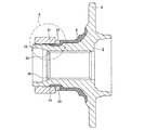
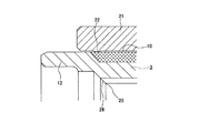
上述の様に、上記ハブ3に所定の加工及び熱処理を施したならば、上記荒加工を施したこのハブ3の中心孔に仕上げのブローチ加工を施して上記スプライン孔14(図1〜2は、スプライン孔14の仕上加工前の荒加工の状態を示している。)を形成する。本実施例の場合、図1〜2に示す様に、この仕上げのブローチ加工を施す際に、上記熱処理を施していない生のままの上記円筒部12の外周面に治具21を外嵌して、この円筒部12の外周面の軸方向一部を径方向内方に向けて圧縮する。この治具21は、全体が円筒状に形成されており、内周面の軸方向内端寄り部分に、径方向内方に突出する突条22を全周に亙って設けている。この突条22の内径dは、上記円筒部12の自由状態での外径よりも僅かに小さく、上記治具21のこの突条22を除く内周面の内径Dは、この円筒部12の自由状態での外径とほぼ同径となる様に、それぞれ形成している。この為、上記治具21を上記円筒部12に外嵌した場合、上記突条22により上記円筒部12の外周面の軸方向一部が径方向内方に圧縮される。尚、図2では、上記治具21の突条22を除く内周面と上記円筒部12の外周面との間に、構造を明確にする為に、明らかな隙間を存在させているが、実際にはこの隙間は極く小さい。即ち、上記治具21の内周面と上記円筒部12の外周面との寸法誤差及び、上記突条22の存在によるこれら各周面の弾性変形分による僅かな隙間が存在するのみである。   As described above, if the hub 3 is subjected to predetermined processing and heat treatment, the center hole of the hub 3 subjected to the roughing is subjected to finishing broaching to form the spline hole 14 (FIGS. 1-2). , A rough machining state before finishing of the spline hole 14 is shown.). In the case of the present embodiment, as shown in FIGS. 1 and 2, when performing this broaching process, a jig 21 is externally fitted on the outer peripheral surface of the raw cylindrical portion 12 that has not been subjected to the heat treatment. Thus, a part in the axial direction of the outer peripheral surface of the cylindrical portion 12 is compressed inward in the radial direction. The jig 21 is formed in a cylindrical shape as a whole, and is provided with a protrusion 22 projecting radially inward over the entire circumference at a portion near the inner end in the axial direction of the inner peripheral surface. The inner diameter d of the protrusion 22 is slightly smaller than the outer diameter of the cylindrical portion 12 in the free state, and the inner diameter D of the inner peripheral surface of the jig 21 excluding the protrusion 22 is the same as that of the cylindrical portion 12. Each is formed so as to have substantially the same diameter as the outer diameter in the free state. For this reason, when the jig 21 is externally fitted to the cylindrical portion 12, a part of the outer peripheral surface of the cylindrical portion 12 in the axial direction is compressed radially inward by the protrusion 22. In FIG. 2, there is a clear gap between the inner peripheral surface of the jig 21 excluding the protrusion 22 and the outer peripheral surface of the cylindrical portion 12 in order to clarify the structure. In practice, this gap is very small. That is, there are only dimensional errors between the inner peripheral surface of the jig 21 and the outer peripheral surface of the cylindrical portion 12 and a slight gap due to the elastic deformation of each peripheral surface due to the presence of the protrusions 22.

又、本実施例の場合、上記治具21を上記円筒部12の外周面に外嵌した時に、この治具21の内周面に設けた上記突条22の位置を、この円筒部12の熱処理を施していない生の部分の外周面で、上記スプライン孔14を形成する前の状態のこのスプライン孔14の内端部に相当する位置(内端部相当位置25)よりも軸方向内方となる様に規制する。尚、この内端部相当位置25は、図示の様に、後述する仕上加工を施す事によりスプラインを形成する凹凸部分の内端部に存在する傾斜した部分(傾斜面部26)を除いた状態での軸方向内端部を指す。又、前述した様に、荒加工の為のブローチ加工を施さない場合も、上記傾斜面部26を除いた状態での軸方向内端部が、上記内端部相当位置25となる。尚、この傾斜面部26は、スプライン軸16(図13参照)を挿入する為の案内面となる。   In the case of this embodiment, when the jig 21 is fitted on the outer peripheral surface of the cylindrical portion 12, the position of the protrusion 22 provided on the inner peripheral surface of the jig 21 is changed to the position of the cylindrical portion 12. On the outer peripheral surface of the raw part that has not been heat-treated, it is axially inward from a position corresponding to the inner end of the spline hole 14 before the spline hole 14 is formed (inner end corresponding position 25). It regulates to become. As shown in the figure, the inner end equivalent position 25 is in a state in which an inclined portion (inclined surface portion 26) existing at the inner end portion of the concavo-convex portion forming the spline is removed by performing finishing processing described later. It points to the inner end in the axial direction. Further, as described above, even when broaching for roughing is not performed, the axially inner end portion excluding the inclined surface portion 26 becomes the inner end portion corresponding position 25. The inclined surface portion 26 serves as a guide surface for inserting the spline shaft 16 (see FIG. 13).

図示の例では、上述の様に、上記突条22の軸方向位置を規制する為、上記治具21と、上記ハブ3の中間部外周面と前記小径段部10との段差面23との間に、所定の軸方向寸法を有する間座24を外嵌している。この間座24は、上記治具21の位置決めの為に設けるものである為、上記ハブ3の外周面に対して締り嵌めとする必要はない。これに対して、上記治具21は、上記突条22部分で、上記円筒部12に対し締り嵌めとなる。この為、この治具21をこの円筒部12に外嵌する際には、プレス機等により圧入する。尚、上記治具21の軸方向寸法を長くして、この治具21の外端面を上記段差面23に当接させる様にすれば、上記間座24を省略する事もできる。   In the illustrated example, as described above, in order to restrict the axial position of the protrusion 22, the jig 21 and the stepped surface 23 between the outer peripheral surface of the intermediate portion of the hub 3 and the small diameter stepped portion 10 are provided. A spacer 24 having a predetermined axial dimension is externally fitted therebetween. Since the spacer 24 is provided for positioning the jig 21, it is not necessary to make an interference fit with the outer peripheral surface of the hub 3. On the other hand, the jig 21 is an interference fit with the cylindrical portion 12 at the protrusion 22 portion. For this reason, when this jig 21 is fitted on the cylindrical portion 12, it is press-fitted by a press machine or the like. The spacer 24 can be omitted if the axial dimension of the jig 21 is increased and the outer end surface of the jig 21 is brought into contact with the stepped surface 23.

又、本実施例の場合、上記治具21を上記円筒部12に外嵌する事により、上記内端部相当位置25に生じる応力を140〜400MPa としている。この為に、上記突条22の上記治具21の内周面からの突出量δ{(D−d)/2}を、0.18〜0.25mmとしている。又、上記突条22の断面形状を、半径が2〜10mmの円弧形としている。又、この突条22の軸方向位置を、上記段差面23からの軸方向距離L22が20.1〜22.1mmとなる位置としている。この場合、上記内端部相当位置25から上記突条22までの軸方向距離L25が8〜13mmである。これらの値は、一般的な乗用車用の駆動輪用転がり軸受ユニットの場合である。尚、この様に規制する理由に就いては、後述する。 In the case of the present embodiment, the stress generated at the inner end equivalent position 25 is 140 to 400 MPa by fitting the jig 21 to the cylindrical portion 12. Therefore, the protrusion amount δ {(D−d) / 2} of the protrusion 22 from the inner peripheral surface of the jig 21 is set to 0.18 to 0.25 mm. Moreover, the cross-sectional shape of the said protrusion 22 is made into the circular arc shape whose radius is 2-10 mm. Further, the axial position of the ridge 22 is set such that the axial distance L 22 from the step surface 23 is 20.1 to 22.1 mm. In this case, the axial distance L 25 from the inner end equivalent position 25 to the ridge 22 is 8 to 13 mm. These values are for the case of a general rolling bearing unit for driving wheels for passenger cars. The reason for such restriction will be described later.

上述の様に、円筒部12に治具21を外嵌する事により、この円筒部12の軸方向一部を圧縮した状態では、図3に誇張して示す様に、上記内端部相当位置25が径方向内方に変位する。本実施例の場合、上記円筒部12に外嵌する治具21の内周面に設けた突条22の突出量δや軸方向距離L22等を、上述の様に規制している。この為、上記治具21を上記円筒部12に外嵌した時に、上記内端部相当位置25が膨出する量を、後述する、かしめ部13形成時にスプライン孔14の内端部が径方向内方に変位する量との関係で適正にできる。そして、この状態で、上記仕上げのブローチ加工を施して、上記スプライン孔14を形成する。このスプライン孔14を形成したならば、上記円筒部12の外周面から上記治具21を取り外す。この治具21を取り外す際には、この治具21の外端面で前記間座24よりも径方向外方に突出している部分を固定の部分に引っ掛けた状態で、上記ハブ3を軸方向内方から外方にプレスして、上記治具21の内周面から上記円筒部12を押し出す。尚、上記間座24は、前述の様に、上記ハブ3の外周面に対して緩く嵌合している為、取り外しは容易である。 As described above, in a state where a part of the cylindrical portion 12 in the axial direction is compressed by fitting the jig 21 to the cylindrical portion 12, the position corresponding to the inner end portion is exaggerated as shown in FIG. 25 is displaced radially inward. In the case of the present embodiment, the protrusion amount δ of the protrusion 22 provided on the inner peripheral surface of the jig 21 fitted on the cylindrical portion 12 and the axial distance L 22 are restricted as described above. For this reason, when the jig 21 is externally fitted to the cylindrical portion 12, the amount by which the inner end equivalent position 25 bulges will be described later. The inner end portion of the spline hole 14 is radial when the caulking portion 13 is formed. It can be made appropriate in relation to the amount of inward displacement. In this state, the finishing broaching is performed to form the spline hole 14. When the spline hole 14 is formed, the jig 21 is removed from the outer peripheral surface of the cylindrical portion 12. When the jig 21 is removed, the hub 3 is moved in the axial direction with the outer end surface of the jig 21 projecting radially outward from the spacer 24 to the fixed part. The cylindrical portion 12 is pushed out from the inner peripheral surface of the jig 21 by pressing from one side to the outside. Since the spacer 24 is loosely fitted to the outer peripheral surface of the hub 3 as described above, it can be easily removed.

上述の様に、治具21を上記円筒部12から取り外す事により、上記スプライン孔14の内端部の形状が、図4に誇張して示す様に、軸方向内方に向かう程径方向外方に拡がった状態となる。即ち、上記スプライン孔14の加工時に上記内端部相当位置25に作用していた圧縮応力が、上記治具21を上記円筒部12から取り外す事により解除される。この結果、上記スプライン孔14の内端部が弾性的に復元する。本実施例の場合、上記内端部相当位置25が径方向内方に変位した状態で、上記スプライン孔14を形成する為のブローチ加工を施している為、この変位した部分は、この加工の際に除去される。従って、上述の様に、スプライン孔14を形成した後に、このスプライン孔14の内端部が弾性的に復元した状態では、上記変位した部分が除去されている分、この内端部が径方向外方に拡がった様な形状を有する事となる。   As described above, by removing the jig 21 from the cylindrical portion 12, the shape of the inner end portion of the spline hole 14 is increased radially outward as it goes inward in the axial direction as shown exaggeratedly in FIG. It will be in a state of spreading to the direction. That is, the compressive stress acting on the inner end portion corresponding position 25 when the spline hole 14 is processed is released by removing the jig 21 from the cylindrical portion 12. As a result, the inner end portion of the spline hole 14 is elastically restored. In the case of this embodiment, since the inner end equivalent position 25 is displaced inward in the radial direction, the broaching process for forming the spline hole 14 is performed. When removed. Therefore, after the spline hole 14 is formed as described above, in the state where the inner end portion of the spline hole 14 is elastically restored, the displaced end portion is removed so that the inner end portion is in the radial direction. It will have a shape that spreads outward.

そして、本実施例の場合、上記スプライン孔14の内端部の形状が拡がった状態で、上記円筒部12にかしめ加工を施して前記かしめ部13を形成する。即ち、上記ハブ3の中心部にスプライン孔14を形成した後、小径段部10に内輪4(図13参照)を外嵌し、この内輪4の外端面を前記段差面23に当接させる。この状態で、上記ハブ3及び内輪4の周囲に外輪2を配置して、この外輪2の内周面に形成した外輪軌道7、7と、上記ハブ3及び内輪4の外周面に形成した第一、第二の内輪軌道9、11との間に、転動体5、5を保持器に保持した状態で組み付ける(図13参照)。この様に各部材を組み付けたならば、上記ハブ3の外端面を支持台に載置して、上記円筒部12に揺動かしめ等のかしめ加工を行なう。この様にかしめ加工を行なう際には、上記外輪2を回転させながら行なう。尚、このかしめ加工に就いては、従来から行なわれているかしめ加工と同様に行なう為、詳しい説明は省略する。   In the case of this embodiment, the caulking portion 13 is formed by caulking the cylindrical portion 12 with the shape of the inner end portion of the spline hole 14 expanded. That is, after the spline hole 14 is formed in the center portion of the hub 3, the inner ring 4 (see FIG. 13) is externally fitted to the small diameter step portion 10, and the outer end surface of the inner ring 4 is brought into contact with the step surface 23. In this state, the outer ring 2 is arranged around the hub 3 and the inner ring 4, and outer ring raceways 7 and 7 formed on the inner peripheral surface of the outer ring 2, and the outer ring 2 formed on the outer peripheral surface of the hub 3 and the inner ring 4. The rolling elements 5 and 5 are assembled between the first and second inner ring raceways 9 and 11 while being held by the cage (see FIG. 13). When the members are assembled in this manner, the outer end surface of the hub 3 is placed on a support base, and the cylindrical portion 12 is subjected to caulking such as swing caulking. When caulking is performed in this manner, the outer ring 2 is rotated. Since this caulking process is performed in the same manner as the caulking process that has been conventionally performed, detailed description thereof is omitted.

上述の様なかしめ加工を施す事により、上記ハブ3の内端部にかしめ部13を形成した状態で、上記スプライン孔14の内端部は、軸方向とほぼ平行となる。即ち、かしめ加工時に作用する荷重により、このスプライン孔14の内端部は径方向内方に変位するが、かしめ加工を施す前のこのスプライン孔14の内端部の形状は径方向外方に拡がった状態である為、かしめ加工時にこの内端部が変位する量が相殺される。特に、本実施例の場合、上記スプライン孔14を形成する際に上記円筒部12の圧縮状態を規制する事により、上記内端部相当位置25の変位量を適正にしている。この為、上記スプライン孔14の形成後にこのスプライン孔14の内端部が径方向外方に拡がる量を、かしめ部13形成時にこのスプライン孔14の内端部が径方向内方に変位する量とほぼ同じとする事ができる。この結果、上記かしめ部13を形成した後の上記スプライン孔14の内端部の形状の、軸方向に対する平行度を良好にする事ができる。この様に、かしめ部13を形成した後に、スプライン孔14の内端部の軸方向に対する平行度が良好であれば、等速ジョイント15のスプライン軸16(図13参照)を挿通しにくくなる等の不具合の発生を抑える事ができる。   By performing the caulking process as described above, the inner end portion of the spline hole 14 is substantially parallel to the axial direction in a state where the caulking portion 13 is formed at the inner end portion of the hub 3. That is, the inner end portion of the spline hole 14 is displaced inward in the radial direction due to a load acting during caulking, but the shape of the inner end portion of the spline hole 14 before caulking is radially outward. Since it is in the expanded state, the amount of displacement of the inner end portion during caulking is offset. In particular, in the case of the present embodiment, the amount of displacement of the inner end equivalent position 25 is made appropriate by restricting the compression state of the cylindrical portion 12 when the spline hole 14 is formed. Therefore, the amount by which the inner end portion of the spline hole 14 expands radially outward after the spline hole 14 is formed, and the amount by which the inner end portion of the spline hole 14 is displaced radially inward when the caulking portion 13 is formed. Can be almost the same. As a result, the parallelism with respect to the axial direction of the shape of the inner end portion of the spline hole 14 after the caulking portion 13 is formed can be improved. Thus, if the parallelism with respect to the axial direction of the inner end part of the spline hole 14 is good after the caulking part 13 is formed, it becomes difficult to insert the spline shaft 16 (see FIG. 13) of the constant velocity joint 15. The occurrence of problems can be suppressed.

上述の様に構成される本実施例により、かしめ部13を形成した後のスプライン孔14の内端部の軸方向に対する平行度を良好にできる理由に就いて、詳しく説明する。
先ず、円筒部12の外周面を圧縮する事により内端部相当位置25を変位させる量を、どの様な値とすれば良いか検討する。本実施例の場合、前述した様に、上記円筒部12の外周面の軸方向一部を径方向内方に向けて圧縮する事により上記内端部相当位置25を変位させた部分を、仕上げのブローチ加工を施してスプライン孔14を形成する際に除去する。従って、上記円筒部12を圧縮する事による上記内端部相当位置25の径方向内方への変位量と、かしめ加工時に作用するスラスト荷重によりスプライン孔14の内端部が径方向内方に変位する量とをほぼ同じとする事ができれば、かしめ加工によりこのスプライン孔14の内端部が変位する部分を予め除去できる事となる。そして、この様に、かしめ加工により変位する量を予め除去できれば、同じ条件でかしめ加工を行なった場合に、上記スプライン孔14の内端部の形状の軸方向に対する平行度を良好にできる。
The reason why the parallelism with respect to the axial direction of the inner end portion of the spline hole 14 after the formation of the caulking portion 13 can be improved according to the present embodiment configured as described above will be described in detail.
First, what value should be taken for the amount of displacement of the inner end portion equivalent position 25 by compressing the outer peripheral surface of the cylindrical portion 12 is examined. In the case of the present embodiment, as described above, the portion where the inner end equivalent position 25 is displaced by compressing a part in the axial direction of the outer peripheral surface of the cylindrical portion 12 inward in the radial direction is finished. This is removed when the spline hole 14 is formed by performing broaching. Therefore, the inner end portion of the spline hole 14 is brought radially inward by the amount of displacement of the inner end portion corresponding position 25 radially inward by compressing the cylindrical portion 12 and the thrust load acting during caulking. If the amount of displacement can be made substantially the same, the portion where the inner end portion of the spline hole 14 is displaced can be removed in advance by caulking. If the amount displaced by caulking can be removed in this way, the parallelism of the shape of the inner end of the spline hole 14 with respect to the axial direction can be improved when caulking is performed under the same conditions.

従って、本発明者は、以下の様に、かしめ加工後のスプライン孔14の内端部の形状が軸方向とほぼ平行となる様な、このスプライン孔14の形成時に上記円筒部12の外周面を圧縮する際の上記内端部相当位置25の目標形状を求めた。
最初に、この内端部相当位置25の許容変形量に就いて検討する。上記ハブ3の材料としては、通常、S45C〜S55Cの如き機械構造用炭素鋼(JIS G 4051)等の鋼材が使用される。この材料の降伏点は約400MPa である。この為、上記内端部相当位置25に作用する応力を400MPa 以下に抑える必要がある。言い換えれば、この内端部相当位置25に作用する応力が400MPa を越えた場合には、この内端部相当位置25が塑性変形してしまう。この様に、内端部相当位置25に作用する応力の許容値を400MPa 以下とした場合、本発明が対象とする普通自動車用の駆動輪用転がり軸受ユニットを構成するハブの大きさでは、上記内端部相当位置25の許容変形量は約0.03mmとなる。従って、この内端部相当位置25の変形量が0.03mmを越えた場合には、この内端部相当位置25が塑性変形してしまう。この為、本発明者は、この内端部相当位置25の許容変形量を0.03mmとした。尚、本実施例の場合、この内端部相当位置25よりも軸方向内方部分に、この内端部相当位置25に作用する応力よりも大きな応力が作用すると考えられるが、この部分は、かしめ部13となる部分である為、仮に塑性変形しても問題ない。
Accordingly, the present inventor considered that the outer peripheral surface of the cylindrical portion 12 is formed when the spline hole 14 is formed such that the shape of the inner end portion of the spline hole 14 after caulking is substantially parallel to the axial direction as follows. The target shape of the inner end equivalent position 25 when compressing was calculated.
First, the allowable deformation amount of the inner end equivalent position 25 will be examined. As the material of the hub 3, steel materials such as carbon steel for machine structure (JIS G 4051) such as S45C to S55C are usually used. The yield point of this material is about 400 MPa. For this reason, it is necessary to suppress the stress acting on the inner end equivalent position 25 to 400 MPa or less. In other words, when the stress acting on the inner end equivalent position 25 exceeds 400 MPa, the inner end equivalent position 25 is plastically deformed. As described above, when the allowable value of the stress acting on the inner end equivalent position 25 is 400 MPa or less, the size of the hub constituting the driving wheel rolling bearing unit for a normal automobile targeted by the present invention is as described above. The allowable deformation amount at the inner end portion corresponding position 25 is about 0.03 mm. Therefore, when the deformation amount of the inner end equivalent position 25 exceeds 0.03 mm, the inner end equivalent position 25 is plastically deformed. For this reason, the present inventors set the allowable deformation amount of the inner end equivalent position 25 to 0.03 mm. In the case of the present embodiment, it is considered that a stress larger than the stress acting on the inner end equivalent position 25 acts on the inner part in the axial direction than the inner end equivalent position 25. Since it is a portion that becomes the caulking portion 13, there is no problem even if it is plastically deformed.

上述の様に、内端部相当位置25の許容変形量を、0.03mmとした為、かしめ加工による上記スプライン孔14の内端部の変位量も0.03mm以下に抑える必要がある。即ち、前述の様に、かしめ加工後にこのスプライン孔14の内端部の形状を軸方向とほぼ平行とする為には、円筒部12を圧縮する事により上記内端部相当位置25が径方向内方に弾性的に変位する量と、かしめ加工に伴って上記スプライン孔14の内端部が径方向内方に変位する量とを、ほぼ同じにしなければならない。従って、上記内端部相当位置25の許容変形量が0.03mm以下であれば、かしめ加工による上記スプライン孔14の内端部の径方向内方への変位量も、0.03mm以下とする必要がある。尚、かしめ加工による上記スプライン孔14の内端部の、径方向内方への変位量を小さく抑える為には、かしめ加工の条件を次の様にする。
揺動角度 : 大きくする
揺動回転数 : 上げる
ストローク速さ : 遅くする
As described above, since the allowable deformation amount at the inner end portion corresponding position 25 is 0.03 mm, the displacement amount of the inner end portion of the spline hole 14 by caulking must be suppressed to 0.03 mm or less. That is, as described above, in order to make the shape of the inner end portion of the spline hole 14 substantially parallel to the axial direction after caulking, the cylindrical portion 12 is compressed so that the inner end equivalent position 25 is set in the radial direction. The amount that is elastically displaced inward and the amount that the inner end portion of the spline hole 14 is displaced radially inward with the caulking process must be substantially the same. Therefore, if the allowable deformation amount at the inner end portion corresponding position 25 is 0.03 mm or less, the amount of displacement of the inner end portion of the spline hole 14 in the radial direction by caulking is also set to 0.03 mm or less. There is a need. In order to suppress the amount of displacement of the inner end portion of the spline hole 14 in the radial direction by caulking, the caulking conditions are as follows.
Oscillation angle: Increase Oscillation speed: Increase Stroke speed: Decrease

上述の様な条件を考慮して、本発明者は次の条件(1)、(2)の様に、かしめ部13を形成する為の押型或はロール等の揺動部材の揺動角度等を規制してかしめ加工を行ない、それぞれの場合のスプライン孔14の内端部の変形状態を求めた。尚、揺動部材の揺動回転速度及びストローク速さに就いては、条件(1)、(2)共に同じ条件であり、揺動角度のみ異ならせた。
揺動角度 : 5°{条件(1)}、2°{条件(2)}
揺動回転速度 : 200〜500min-1
ストローク速さ : 3mm/s
In consideration of the above-described conditions, the present inventor, as in the following conditions (1) and (2), has a swing angle of a swing member such as a pressing die or a roll for forming the caulking portion 13. And the deformation state of the inner end portion of the spline hole 14 in each case was obtained. The swinging speed and stroke speed of the swinging member are the same in both conditions (1) and (2), and only the swinging angle is varied.
Oscillation angle: 5 ° {condition (1)}, 2 ° {condition (2)}
Oscillating rotation speed: 200-500min -1
Stroke speed: 3mm / s

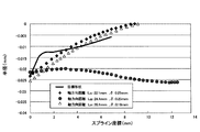
上記各条件(1)、(2)によりかしめ加工を行なった実験の結果を図5に示す。この図5には、これら各条件(1)、(2)によりかしめ加工を行なった場合に於ける、スプライン孔14の内端部が径方向内方に変位した量をそれぞれ示している。尚、上記図5及び後述する図6、7、9〜12に示す、このスプライン孔14の内端部(或は内端部相当位置25)の変位量は、このスプライン孔14の内端部(或は内端部相当位置25)の半径の変化量を、上記スプライン孔14の内端部(或は内端部相当位置25)からの軸方向の距離との関係で示している。従って、それぞれマイナス表示となる。上記図5からも明らかな様に、上記条件(2)によりかしめ加工を行なった場合、上記スプライン孔14の内端部の変位量が0.03mmを越えた。これに対して、上記条件(1)によりかしめ加工を行なった場合、上記スプライン孔14の内端部の変位量を0.03mm以下に抑える事ができた。従って、かしめ加工の条件は、上記条件(1)で行なえば良い事が分かった。   FIG. 5 shows the results of an experiment in which caulking is performed under the above conditions (1) and (2). FIG. 5 shows the amount of displacement of the inner end portion of the spline hole 14 radially inward when caulking is performed under these conditions (1) and (2). The displacement amount of the inner end portion (or inner end portion equivalent position 25) of the spline hole 14 shown in FIG. 5 and FIGS. The amount of change in the radius of the (or inner end equivalent position 25) is shown in relation to the axial distance from the inner end (or inner end equivalent position 25) of the spline hole 14. Accordingly, the display is negative. As is apparent from FIG. 5, when the caulking process was performed under the condition (2), the displacement amount of the inner end portion of the spline hole 14 exceeded 0.03 mm. On the other hand, when caulking was performed under the condition (1), the amount of displacement of the inner end portion of the spline hole 14 could be suppressed to 0.03 mm or less. Therefore, it has been found that the caulking process may be performed under the above condition (1).

尚、揺動部材の揺動回転速度を上げたり、ストローク速さを遅くする事によって、上記スプライン孔14の内端部の変位量を更に小さくできる。但し、この内端部の変位量は、0.03mm以下に抑えられれば良いので、従来の生産条件を考慮して、従来から行なっていたかしめ加工の条件を必要以上に変えない様にする事が好ましい。例えば、上述の様に、揺動角度を規制する事により所望の条件を満たせば、揺動回転速度やストローク速さは変えない様にする。この様に、従来の生産条件との変更点を少なくすれば、条件変更に伴う人為的なミス等を減らす事ができる。   The amount of displacement of the inner end portion of the spline hole 14 can be further reduced by increasing the rocking rotation speed of the rocking member or slowing the stroke speed. However, the amount of displacement of the inner end portion only needs to be suppressed to 0.03 mm or less, so that the conventional caulking process conditions should not be changed more than necessary in consideration of the conventional production conditions. Is preferred. For example, as described above, if the desired condition is satisfied by restricting the swing angle, the swing rotational speed and stroke speed are not changed. In this way, if the number of changes from the conventional production conditions is reduced, it is possible to reduce human errors caused by the condition changes.

上述の様に、条件(1)でかしめ加工を行なった場合には、上記スプライン孔14の内端部の径方向の変位量を0.03mm以下に抑えられる為、上記図5に示した条件(1)によりかしめ加工を行なった場合の上記スプライン孔14の内端部の形状を、このスプライン孔14の形成時に上記円筒部12の外周面を圧縮する際の、内端部相当位置25の目標形状とする。尚、本明細書で「内端部相当位置の形状」と言う場合には、内端部相当位置25よりも軸方向外方の所定部分(例えば、内端部相当位置25から10mm程度の部分)を含む概念とする。上記円筒部12の外周面を圧縮する事により、この内端部相当位置25の形状を上記目標形状とする事ができれば、上記円筒部12を圧縮する事によりこの内端部相当位置25が塑性変形する事はない。従って、スプライン孔14の仕上げ加工後に、この円筒部12の外周面の圧縮状態を解除した場合に、このスプライン孔14の内端部の形状を、確実に弾性的に復元させる事ができる。   As described above, when caulking is performed under the condition (1), the radial displacement amount of the inner end portion of the spline hole 14 can be suppressed to 0.03 mm or less. Therefore, the conditions shown in FIG. The shape of the inner end portion of the spline hole 14 when caulking is performed according to (1) is the same as the position 25 corresponding to the inner end portion when the outer peripheral surface of the cylindrical portion 12 is compressed when the spline hole 14 is formed. Use the target shape. In this specification, the “shape of the position corresponding to the inner end portion” refers to a predetermined portion axially outward from the position corresponding to the inner end portion 25 (for example, a portion about 10 mm from the position corresponding to the inner end portion 25). ). If the shape of the inner end portion equivalent position 25 can be made the target shape by compressing the outer peripheral surface of the cylindrical portion 12, the inner end portion equivalent position 25 is made plastic by compressing the cylindrical portion 12. There is no deformation. Therefore, when the compressed state of the outer peripheral surface of the cylindrical portion 12 is released after finishing the spline hole 14, the shape of the inner end portion of the spline hole 14 can be reliably elastically restored.

次に、上述の様に、円筒部12を圧縮する事により、上記内端部相当位置25の形状を目標形状とする為の条件を求める為に行なった実験に就いて説明する。
先ず、上記円筒部12を圧縮する為の治具の形状を、内周面に突条を設けない形状(内周面を軸方向全体に亙って円筒面)とした場合に、上記内端部相当位置25がどの様な形状となるかを調べた実験に就いて説明する。
この実験を行なう為に本発明者は、上記円筒部12を厚肉円筒部材に単純化して、上記内端部相当位置25の形状が上記目標形状となる様な、治具とこの円筒部12との締め代を計算した。即ち、図6に実線で示した上記目標形状の関数U(x) を求め、このU(x) を満たす様な締め代を計算で求めた。そして、実際に、この計算により求めた締め代により、上記円筒部12に治具を外嵌し、上記内端部相当位置25の形状を調べた。この結果を上記図6に示す。
Next, an experiment conducted for obtaining a condition for setting the shape of the inner end equivalent position 25 to the target shape by compressing the cylindrical portion 12 as described above will be described.
First, when the shape of the jig for compressing the cylindrical portion 12 is a shape in which no protrusion is provided on the inner peripheral surface (the inner peripheral surface is the entire cylindrical surface), the inner end An experiment for examining the shape of the part equivalent position 25 will be described.
In order to perform this experiment, the present inventor simplified the cylindrical portion 12 into a thick cylindrical member, and a jig and the cylindrical portion 12 so that the shape of the inner end equivalent position 25 becomes the target shape. And calculated the allowance. That is, the function U (x) of the target shape indicated by the solid line in FIG. 6 is obtained, and a tightening margin that satisfies this U (x) is obtained by calculation. Actually, a jig was externally fitted to the cylindrical portion 12 by the tightening allowance obtained by this calculation, and the shape of the inner end portion corresponding position 25 was examined. The result is shown in FIG.

上記図6から明らかな様に、治具の内周面を軸方向全体に亙って円筒面とした場合には、治具を外嵌して円筒部12の外周面を圧縮した時に、上記内端部相当位置25の形状が上記目標形状から大きく外れてしまう事が分かった。尚、図6には、治具の外端面を段差面23に突き当てた場合と、上記内端部相当位置25の形状を上記目標形状に近付けるべく、この治具の外端面を段差面23に突き当てず、この治具の軸方向に関する位置を微調整した場合との結果を、それぞれ示している。これら各結果は、ほぼ同様な形状となったが、何れの場合も、上記目標形状から大きく外れた。   As is clear from FIG. 6 above, when the inner peripheral surface of the jig is a cylindrical surface over the entire axial direction, the outer surface of the cylindrical portion 12 is compressed when the jig is fitted and the outer peripheral surface is compressed. It has been found that the shape of the inner end equivalent position 25 deviates greatly from the target shape. FIG. 6 shows the case where the outer end surface of the jig is abutted against the step surface 23 and the outer end surface of the jig is set to the step surface 23 in order to bring the shape of the inner end equivalent position 25 closer to the target shape. The result when the position in the axial direction of the jig is finely adjusted without being abutted on the case is shown. Each of these results had almost the same shape, but in any case, it was significantly different from the target shape.

上述の様に、目標形状から大きく外れた原因として次の様な事が考えられる。即ち、上記目標形状は、通常のかしめ加工によりかしめ部13を形成した時の、スプライン孔14の内端部の変形状態である為、塑性変形により形成された形状である。これに対して、上述の様な締め代の計算は、弾性変形モデルに就いて行なっている為、上記治具の直径が弾性的に拡がって、目標形状から大きく外れたと考えられる。尚、上記締め代の計算を弾性変形モデルとするのは、前述した様に、内端部相当位置25を塑性変形させたくない為、この内端部相当位置25の膨出量を0.03mm以下と規制している事からも分かる様に、本発明が、円筒部12の外周面の一部を圧縮する事により、上記内端部相当位置25を適性量弾性変形させる事を目的とする為である。従って、上記計算は弾性変形モデルのみを対象に行なった。   As described above, the following may be considered as the cause of the large deviation from the target shape. That is, the target shape is a shape formed by plastic deformation because the inner end portion of the spline hole 14 is deformed when the caulking portion 13 is formed by a normal caulking process. On the other hand, since the calculation of the tightening allowance as described above is performed for the elastic deformation model, it is considered that the diameter of the jig is elastically expanded and greatly deviates from the target shape. The reason for calculating the tightening allowance is to use the elastic deformation model, as described above, because the inner end equivalent position 25 does not want to be plastically deformed. Therefore, the bulging amount of the inner end equivalent position 25 is set to 0.03 mm. As can be seen from the following regulation, the present invention aims to elastically deform the inner end equivalent position 25 by a suitable amount by compressing a part of the outer peripheral surface of the cylindrical portion 12. Because of that. Therefore, the above calculation was performed only for the elastic deformation model.

又、本発明者は、締め代を上記計算により求めた値とし、治具の外径を規制してこの治具の直径が弾性的に拡がる事を抑える事により、上記内端部相当位置25の形状を目標形状とする事に就いても検討した。しかし、この治具の外径が円筒部12の外径に比べて大きくなり過ぎ、この治具を外嵌した場合に不安定となる為、治具の外径を規制して上記内端部相当位置25の形状を目標形状とする事は、現実的でないと判断した。   Further, the inventor sets the tightening margin to the value obtained by the above calculation, restricts the outer diameter of the jig, and suppresses the elastic expansion of the diameter of the jig, whereby the inner end equivalent position 25 is obtained. We also considered the target shape as the target shape. However, since the outer diameter of the jig is too large compared to the outer diameter of the cylindrical portion 12 and becomes unstable when the jig is externally fitted, the outer diameter of the jig is restricted and the inner end portion is restricted. It was determined that it was not realistic to set the shape of the equivalent position 25 as the target shape.

次に、本実施例の様に、治具の内周面の軸方向一部に突条を形成した場合に、内端部相当位置25がどの様な形状となるかを調べた実験に就いて説明する。
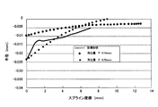
先ず、前述の図1〜2に示した様に、その内周面の軸方向一部に突条22を設けた治具21を高周波焼き入れ等の熱処理を施していない生の部分の円筒部12に外嵌した場合の、内端部相当位置25の変形状態を調べた。この実験では、上記治具21を円筒部12に外嵌した状態で上記突条22の軸方向の位置を、段差面23からの軸方向距離L22が22.1mmとして、上記内端部相当位置25よりも軸方向内方となる様にした。又、この突条22の突出量δを0.25mmとした。又、この突条22の断面形状は、半径が5mmの円弧状とした。更に、上記治具21の外径は、上記円筒部12の外径の1.3倍とした。この実験結果を、図7に示す。この図7から明らかな様に、上記治具21を円筒部12に、上述した条件で外嵌した場合には、上記内端部相当位置25の形状を、上記目標形状に近くできる事が分かった。
Next, as in this example, when a protrusion was formed on a part of the inner peripheral surface of the jig in the axial direction, an experiment was conducted to determine what shape the inner end equivalent position 25 would have. And explain.
First, as shown in FIGS. 1 and 2 described above, the cylindrical portion of the raw portion where the jig 21 provided with the protrusions 22 on a part of the inner peripheral surface in the axial direction is not subjected to heat treatment such as induction hardening. The deformation state of the inner end portion corresponding position 25 when it was externally fitted to 12 was examined. In this experiment, the axial position of the protrusion 22 in the state where the jig 21 is fitted on the cylindrical portion 12 is set to an axial distance L 22 from the step surface 23 of 22.1 mm, which corresponds to the inner end portion. It was set to be inward in the axial direction from the position 25. The protrusion amount δ of the protrusion 22 was 0.25 mm. The cross-sectional shape of the ridge 22 was an arc having a radius of 5 mm. Furthermore, the outer diameter of the jig 21 was 1.3 times the outer diameter of the cylindrical portion 12. The experimental results are shown in FIG. As can be seen from FIG. 7, when the jig 21 is externally fitted to the cylindrical portion 12 under the above-described conditions, the shape of the inner end equivalent position 25 can be close to the target shape. It was.

尚、上記突条22の突出量δの値は、次の様な方法で求めた。先ず、この突条22の突出量δを適当な値に設定した。ここでは、このδが0.10mmとなる様にこの突条22を形成した。そして、この様な突条22を有する治具21を上記円筒部12に外嵌した。そして、この時に形成される上記内端部相当位置25の形状と目標形状とを比較して、この内端部相当位置25の変位量が目標形状の変位量に対して何倍であるかを求めた。上記δを0.10mmとした場合の内端部相当位置25の変位量は、上記図7に示す様に、約0.01mmである。これに対して、上記目標形状の変位量は、約0.025mmである。従って、この目標形状の変位量は、上記δが0.01mmの時の変位量の2.5倍である事が分かる。上記突条22の突出量と上記内端部相当位置25の変位量とはほぼ比例するので、上記突出量δ(0.10mm)を2.5倍して、突出量δを0.25mmとすれば、上記目標形状の膨出量(0.025mm)が得られる。本実験では、この様にして、上記突条22の突出量δ(0.25mm)を求めた。   In addition, the value of the protrusion amount δ of the protrusion 22 was obtained by the following method. First, the protrusion amount δ of the protrusion 22 was set to an appropriate value. Here, this protrusion 22 was formed so that this δ would be 0.10 mm. And the jig | tool 21 which has such a protrusion 22 was externally fitted to the said cylindrical part 12. FIG. Then, the shape of the inner end equivalent position 25 formed at this time is compared with the target shape to determine how many times the displacement amount of the inner end equivalent position 25 is larger than the displacement of the target shape. Asked. As shown in FIG. 7, the displacement amount of the inner end equivalent position 25 when δ is 0.10 mm is about 0.01 mm. On the other hand, the displacement amount of the target shape is about 0.025 mm. Therefore, it can be seen that the amount of displacement of the target shape is 2.5 times the amount of displacement when δ is 0.01 mm. Since the protrusion amount of the protrusion 22 and the displacement amount of the inner end equivalent position 25 are substantially proportional, the protrusion amount δ (0.10 mm) is multiplied by 2.5, and the protrusion amount δ is 0.25 mm. Then, the bulging amount (0.025 mm) of the target shape can be obtained. In this experiment, the protrusion amount δ (0.25 mm) of the protrusion 22 was thus obtained.

又、上記内端部相当位置25の変位量が0.01mm(突条22の突出量δが0.10mm)の時のこの内端部相当位置25に生じる応力は133.7MPa であった。これに対して、この内端部相当位置25の変位量が0.025mm(δが0.25mm)の時のこの内端部相当位置25に生じる応力は330.4MPa であった。スプライン孔14形成後のこのスプライン孔14の内端部の平行度を考慮した場合、上記内端部相当位置25の変位量を、最低でも0.01mm程度確保する必要がある。即ち、この内端部相当位置25の変位量が0.01mmよりも小さい場合、上記スプライン孔14の形成時に除去される量が少なくなる。この為、かしめ部13の形成時にこのスプライン孔14の内端部が変位する際に相殺できる量も少なくなり、この内端部が、このスプライン孔14の軸方向と平行な部分よりも径方向内方に突出する量が多くなる。この結果、このスプライン孔14内にスプライン軸16を挿通しづらくなると言う不具合を防止できない。上述した様に、上記内端部相当位置25の変位量が0.01mmの時のこの内端部相当位置25に生じる応力が133.7MPa である為、本実施例の場合、この内端部相当位置25に作用する応力の下限を140MPa として、この内端部相当位置25の変位量を確実に0.01mm以上確保する様にしている。尚、上限に就いては、前述した様に、材料の降伏点を考慮して400MPa としている。   Further, when the displacement amount at the inner end portion corresponding position 25 is 0.01 mm (the protrusion amount δ of the protrusion 22 is 0.10 mm), the stress generated at the inner end portion corresponding position 25 is 133.7 MPa. On the other hand, when the displacement amount of the inner end equivalent position 25 is 0.025 mm (δ is 0.25 mm), the stress generated at the inner end equivalent position 25 is 330.4 MPa. Considering the parallelism of the inner end portion of the spline hole 14 after the spline hole 14 is formed, it is necessary to secure a displacement amount of the inner end portion corresponding position 25 of about 0.01 mm at a minimum. That is, when the displacement amount of the inner end portion equivalent position 25 is smaller than 0.01 mm, the amount removed when the spline hole 14 is formed is reduced. For this reason, the amount that can be canceled when the inner end portion of the spline hole 14 is displaced during the formation of the caulking portion 13 is reduced, and the inner end portion is more radial than the portion parallel to the axial direction of the spline hole 14. The amount protruding inward increases. As a result, the problem that it is difficult to insert the spline shaft 16 into the spline hole 14 cannot be prevented. As described above, the stress generated at the inner end equivalent position 25 when the displacement amount at the inner end equivalent position 25 is 0.01 mm is 133.7 MPa. The lower limit of the stress acting on the equivalent position 25 is set to 140 MPa, and the displacement amount of the inner end equivalent position 25 is surely secured to 0.01 mm or more. As described above, the upper limit is set to 400 MPa in consideration of the yield point of the material.

尚、上記突条22の突出量δを0.25mmとした場合、上記円筒部12の外周面上に凹みが形成される。即ち、この円筒部12は、上述した様に、熱処理を施していない生のままである為、上記突条22に押圧される事により、この押圧される部分が径方向内方に凹む。しかし、上記円筒部12の外周面は、かしめ部13の形成時に内輪4の内端面に押し付けられる事により、この内輪4の内端面に倣う様に塑性変形する。この結果、上記凹みがほぼ消失する。本発明者は、この点に就いても実際に確認した。従って、上記突条22により円筒部12の外周面に形成される凹みが、製品の品質に与える影響はないと考えられる。 When the protrusion amount δ of the protrusion 22 is 0.25 mm, a recess is formed on the outer peripheral surface of the cylindrical portion 12. That is, as described above, the cylindrical portion 12 remains raw without being subjected to heat treatment. Therefore, when the cylindrical portion 12 is pressed by the protrusion 22, the pressed portion is recessed inward in the radial direction. However, the outer peripheral surface of the cylindrical portion 12 is plastically deformed to follow the inner end surface of the inner ring 4 by being pressed against the inner end surface of the inner ring 4 when the caulking portion 13 is formed. As a result, the dent almost disappears. The present inventor has actually confirmed this point. Therefore, indentations are formed on the outer peripheral surface of the cylindrical portion 12 by the ridge 22, influence on the quality of the product is considered not.

次に、治具21の内周面に形成する突条22の軸方向位置に就いて検討する。
先ず、本発明者は、図8に示す様に、この突条22を、ハブ3の外周面で、熱処理を施した部分(斜格子で示す部分)である小径段部10の外周面上に位置させた場合の、内端部相当位置25の径方向内方への変位量を調べる実験を行なった。この実験では、上記突条22の軸方向位置を、上記内端部相当位置25の軸方向位置とほぼ同じとした。又、この実験でも、上記突条22の突出量δを、最初、適当な値である0.16mmに設定し、内端部相当位置25の膨出量が目標形状に近付く様に、上記突出量δを調整した。この突出量δが0.10mmで目標形状の変位量に近い値が得られた。この実験の結果を図9に示す。
Next, the axial position of the protrusion 22 formed on the inner peripheral surface of the jig 21 will be examined.
First, as shown in FIG. 8, the present inventor places the protrusion 22 on the outer peripheral surface of the small-diameter step portion 10, which is a heat-treated portion (shown by a slanted lattice), on the outer peripheral surface of the hub 3. An experiment was conducted to examine the amount of radial inward displacement of the inner end portion equivalent position 25 in the case of being positioned. In this experiment, the axial position of the ridge 22 was made substantially the same as the axial position of the inner end equivalent position 25. Also in this experiment, the protrusion amount δ of the protrusion 22 is initially set to an appropriate value of 0.16 mm, and the protrusion amount so that the bulging amount at the inner end equivalent position 25 approaches the target shape. The amount δ was adjusted. This protrusion amount δ was 0.10 mm, and a value close to the displacement amount of the target shape was obtained. The result of this experiment is shown in FIG.

上記図9から明らかな様に、上記突条22を、熱処理を施した部分である上記小径段部10の外周面上に位置させた場合には、上記内端部相当位置25の形状が、目標形状から大きく外れる結果となった。即ち、上記内端部相当位置25の変位量を目標形状の変位量に近付けても、この内端部相当位置25よりも軸方向外方部分が、この目標形状よりも大きく変位した。この結果、上記突条22を上記小径段部10の外周面上に位置させる事により、上記内端部相当位置25を目標形状に近付ける事は難しく、この様な方法は、採用できない事が分かった。尚、上記突出量δが0.10mmの場合には、内端部相当位置25に作用する応力が344.0MPa で、δが0.16mmの場合には、この応力が425.3MPa であった。又、上記内端部相当位置25に作用する応力が425.3MPa で、この内端部相当位置25が塑性変形した事からも明らかな様に、この内端部相当位置25に作用する応力が400MPa を越えると、この内端部相当位置25が塑性変形してしまう。従って、前述した様に、材料の降伏点からこの内端部相当位置25に作用する応力を400MPa 以下とした条件の設定が、正しい事が確認できた。   As apparent from FIG. 9, when the protrusion 22 is positioned on the outer peripheral surface of the small-diameter step portion 10 which is a heat-treated portion, the shape of the inner end equivalent position 25 is The result was far from the target shape. That is, even when the displacement amount of the inner end equivalent position 25 is brought close to the displacement amount of the target shape, the axially outer portion of the inner end equivalent position 25 is displaced more than the target shape. As a result, it is difficult to bring the inner end portion equivalent position 25 close to the target shape by positioning the protrusion 22 on the outer peripheral surface of the small diameter step portion 10, and it is understood that such a method cannot be adopted. It was. When the protrusion δ is 0.10 mm, the stress acting on the inner end equivalent position 25 is 344.0 MPa, and when δ is 0.16 mm, the stress is 425.3 MPa. . The stress acting on the inner end equivalent position 25 is 425.3 MPa, and as is apparent from the plastic deformation of the inner end equivalent position 25, the stress acting on the inner end equivalent position 25 is as follows. If it exceeds 400 MPa, the inner end equivalent position 25 will be plastically deformed. Therefore, as described above, it was confirmed that the setting of the conditions under which the stress acting on the inner end equivalent position 25 from the yield point of the material was 400 MPa or less was correct.

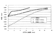
次に、上記突条22の軸方向位置を、前述の図1〜2に示した様に、生のままの部分である円筒部12の外周面に位置させると共に、段差面23からの軸方向距離L22を変化させた場合の、内端部相当位置25の変位量を調べる実験を行なった。この実験は、上記軸方向距離L22が、20.1mm、22.1mm、24.1mmの3種類の場合に就いて行なった。何れの場合も、突条22の断面形状を半径5mmの円弧状とした。又、上記軸方向距離L22が、20.1mmの場合には、突条22の突出量δを0.18mmとする事により、内端部相当位置25の形状を目標形状に近付ける事ができた。又、この軸方向距離L22が22.1mm、24.1mmの場合には、突条22の突出量δを0.25mmとした。この実験の結果を図10に示す。 Next, the axial position of the protrusion 22 is positioned on the outer peripheral surface of the cylindrical portion 12 that is a raw portion as shown in FIGS. distance when the L 22 is varied, an experiment was conducted to examine the amount of displacement of the inner end position corresponding 25. This experiment was conducted when the axial distance L 22 was three types of 20.1 mm, 22.1 mm, and 24.1 mm. In either case, the cross-sectional shape of the ridge 22 was an arc having a radius of 5 mm. Further, when the axial distance L 22 is 20.1 mm, the shape of the inner end equivalent position 25 can be brought close to the target shape by setting the protrusion amount δ of the protrusion 22 to 0.18 mm. It was. When the axial distance L 22 is 22.1 mm and 24.1 mm, the protrusion amount δ of the protrusion 22 is set to 0.25 mm. The result of this experiment is shown in FIG.

上記図10から明らかな様に、上記軸方向距離L22が、20.1mm及び22.1mmの場合には、内端部相当位置25の変位量が目標形状の変位量とほぼ同じとなった。又、形状もこの目標形状に近かった。これに対して、上記軸方向距離L22が24.1mmの場合、この目標形状から大きく外れた。即ち、上記内端部相当位置25よりも軸方向外方部分が、塑性変形してしまい、この内端部相当位置25から離れる程、変位量が大きくなった。従って、本実施例では、上記軸方向距離L22を20.1〜22.1mmとした。又、上記突条22の突出量δは0.18〜0.25mmとした。尚、この時の、突条22の内端部相当位置25からの距離L25は8〜13mmである。又、上記軸方向距離L22が20.1mmの場合に、内端部相当位置25に作用する応力が367.9MPa で、このL22が22.1mmの場合のこの応力が330.4MPa 、L22が24.1mmの場合のこの応力が232.3MPa であった。 As is apparent from FIG. 10, when the axial distance L 22 is 20.1 mm and 22.1 mm, the displacement amount at the inner end portion equivalent position 25 is substantially the same as the displacement amount of the target shape. . The shape was also close to this target shape. On the other hand, when the axial distance L 22 was 24.1 mm, the target shape deviated greatly. That is, the axially outer portion of the inner end portion corresponding position 25 is plastically deformed, and the distance from the inner end portion corresponding position 25 increases as the distance increases. Thus, in this embodiment, the axial distance L 22 and 20.1~22.1Mm. The protrusion amount δ of the protrusion 22 was set to 0.18 to 0.25 mm. At this time, the distance L 25 from the inner end portion equivalent position 25 of the protrusion 22 is 8 to 13 mm. When the axial distance L 22 is 20.1 mm, the stress acting on the inner end portion corresponding position 25 is 367.9 MPa, and when this L 22 is 22.1 mm, this stress is 330.4 MPa, L This stress was 232.3 MPa when 22 was 24.1 mm.

次に、治具21の内周面に形成する突条22の形状が、内端部相当位置25の変形に及ぼす影響に就いて調べた実験に就いて説明する。この実験は、この突条22の断面形状を円弧状とし、半径が2mmと5mmに就いて行なった。又、本実験では、この突条22の突出量δを0.25mmと、この突条22の段差面23からの軸方向距離L22を22.1mmとした。この実験結果を図11に示す。この図11から明らかな様に、上記突条22の半径が2mmの場合と5mmの場合とで、この内端部相当位置25の形状が殆ど同じであった。従って、上記突条22の半径の大きさが、上記内端部相当位置25の変形に及ぼす影響は殆どない事が分かった。但し、この突条22の半径を小さくし過ぎる(2mm未満とする)と、上記治具21を円筒部12から取り外した後に残る凹みが深くなり、好ましくない。これに対して、上記突条22の半径を大きくし過ぎる(10mmより大きくする)と、この突条22により押圧される面積が大きくなり、この突条22を設けた効果が少なくなる。言い換えれば、治具21の内周面を単なる円筒面とした場合と、得られる効果が変わらなくなる。従って、上記突条22の半径は、2〜10mmとする事が好ましい。 Next, an experiment in which the shape of the protrusion 22 formed on the inner peripheral surface of the jig 21 is examined for the influence on the deformation of the inner end equivalent position 25 will be described. In this experiment, the cross-sectional shape of the ridge 22 was an arc, and the radii were 2 mm and 5 mm. In this experiment, the protrusion amount δ of the protrusion 22 was 0.25 mm, and the axial distance L 22 from the step surface 23 of the protrusion 22 was 22.1 mm. The result of this experiment is shown in FIG. As apparent from FIG. 11, the shape of the inner end equivalent position 25 is almost the same when the radius of the protrusion 22 is 2 mm and when it is 5 mm. Therefore, it has been found that the radius of the ridge 22 has almost no influence on the deformation of the inner end equivalent position 25. However, if the radius of the protrusion 22 is too small (less than 2 mm), the dent remaining after the jig 21 is removed from the cylindrical portion 12 becomes deep, which is not preferable. On the other hand, if the radius of the ridge 22 is made too large (greater than 10 mm), the area pressed by the ridge 22 increases, and the effect of providing the ridge 22 is reduced. In other words, the effect obtained is the same as when the inner peripheral surface of the jig 21 is a simple cylindrical surface. Therefore, the radius of the protrusion 22 is preferably 2 to 10 mm.

更に、本発明者は、本発明の効果を実際に確認する実験を行なった。即ち、前述した図1〜4で説明した場合と同様に、スプライン孔14の仕上加工を施す前に、熱処理を施していない生の部分である円筒部12の外周面に治具21を外嵌する事により、内端部相当位置25を径方向内方に変位させた。そして、この状態で、上記スプライン孔14の仕上加工を行なった。その後、上記治具21を上記円筒部12から取り外し、ハブ3に内輪4等を組み付けてから、この円筒部12にかしめ加工を施した。実験条件は、この治具21の内周面に形成した突条22の段差面23からの軸方向距離L22を22.1mmと、この突条22の突出量δを0.25mmと、この突条22の断面形状を半径が5mmの円弧状と、それぞれ規制した。又、上記かしめ加工は、前述の図5で説明した条件(1)により行なった。この実験の結果を図12に示す。 Furthermore, the inventor conducted an experiment to actually confirm the effect of the present invention. That is, as in the case described with reference to FIGS. 1 to 4 described above, before finishing the spline hole 14, the jig 21 is externally fitted to the outer peripheral surface of the cylindrical portion 12 that is a raw portion not subjected to heat treatment. By doing so, the inner end equivalent position 25 was displaced radially inward. In this state, the finishing process of the spline hole 14 was performed. Thereafter, the jig 21 was removed from the cylindrical portion 12 and the inner ring 4 and the like were assembled to the hub 3, and then the cylindrical portion 12 was caulked. The experimental conditions were as follows: the axial distance L 22 from the step surface 23 of the protrusion 22 formed on the inner peripheral surface of the jig 21 was 22.1 mm, and the protrusion amount δ of the protrusion 22 was 0.25 mm. The cross-sectional shape of the protrusion 22 was restricted to an arc shape with a radius of 5 mm. The caulking process was performed under the condition (1) described with reference to FIG. The results of this experiment are shown in FIG.

上記図12は、目標形状と、上記治具21を上記円筒部12に外嵌した時に、上記内端部相当位置25が変位した状態と、スプライン孔14の仕上加工を施して上記治具21を円筒部12から取り外した後に、このスプライン孔14の内端部が拡径した状態と、かしめ部13を形成した後のこのスプライン孔13の内端部の状態とを、それぞれ示している。この実験から、本実施例により得られる、上記スプライン孔14の内端部のかしめ加工後の形状が、軸方に対して平行な形状(図12の半径0mmの部分)に対して±10μm以下の精度に抑えられる事が分かった。   FIG. 12 shows the target shape, the state where the inner end equivalent position 25 is displaced when the jig 21 is externally fitted to the cylindrical portion 12, and the finishing of the spline hole 14. 2 shows a state in which the inner end portion of the spline hole 14 has been expanded after being removed from the cylindrical portion 12 and a state of the inner end portion of the spline hole 13 after the caulking portion 13 is formed. From this experiment, the shape after caulking of the inner end portion of the spline hole 14 obtained by the present embodiment is ± 10 μm or less with respect to the shape parallel to the axial direction (the portion having a radius of 0 mm in FIG. 12). It was found that the accuracy can be suppressed.

本発明の実施例を、円筒部に治具を外嵌した状態で示す断面図。Sectional drawing which shows the Example of this invention in the state which fitted the jig | tool in the cylindrical part. 図1のA部拡大図。The A section enlarged view of FIG. 円筒部に治具を外嵌した状態の内端部相当位置の形状を示す模式図。The schematic diagram which shows the shape of the inner end part equivalent position of the state which fitted the jig | tool in the cylindrical part. 円筒部から治具を外した状態の、スプライン孔の内端部の形状を示す模式図。The schematic diagram which shows the shape of the inner end part of a spline hole in the state which removed the jig | tool from the cylindrical part. 内端部相当位置の目標形状を求める為に行なった実験の結果を示す線図。The diagram which shows the result of the experiment conducted in order to obtain | require the target shape of an inner edge part equivalent position. 内周面に突条を有さない治具を円筒部に外嵌した場合の実験結果を示す線図。The diagram which shows the experimental result at the time of carrying out the external fitting of the jig | tool which does not have a protrusion on an internal peripheral surface to a cylindrical part. 治具の内周面に突条を設けた場合の、この突条の適正な突出量を調べる為に行なった実験の結果を示す線図。The diagram which shows the result of the experiment conducted in order to investigate the proper protrusion amount of this protrusion when a protrusion is provided in the inner peripheral surface of a jig | tool. 突条の軸方位置を熱処理を施した小径段部の外周面上に設置した状態を示す、図2と同様の図。The figure similar to FIG. 2 which shows the state installed in the axial position of a protrusion on the outer peripheral surface of the small diameter step part which heat-processed. 図8の状態で行なった実験の結果を示す線図。The diagram which shows the result of the experiment conducted in the state of FIG. 突条の軸方向位置が、内端部相当位置の変形に及ぼす影響を調べる為に行なった実験の結果を示す線図。The diagram which shows the result of the experiment conducted in order to investigate the influence which the axial direction position of a protrusion exerts on the deformation | transformation of an inner end part equivalent position. 突条の断面形状の半径が及ぼす影響調べる為に行なった実験の結果を示す線図。The diagram which shows the result of the experiment conducted in order to investigate the influence which the radius of the cross-sectional shape of a protrusion exerts. 本発明の効果を確認する為に行なった実験の結果を示す線図。The diagram which shows the result of the experiment conducted in order to confirm the effect of this invention. 本発明の対象となる、駆動輪用転がり軸受ユニットを組み込んだ車輪用駆動ユニットの、従来構造の1例を示す断面図。Sectional drawing which shows one example of the conventional structure of the drive unit for wheels incorporating the rolling bearing unit for drive wheels used as the object of this invention. スプライン孔形成時に円筒部を圧縮する方法の、従来構造の1例を示す断面図。Sectional drawing which shows an example of the conventional structure of the method of compressing a cylindrical part at the time of spline hole formation.

符号の説明Explanation of symbols

1 駆動輪用転がり軸受ユニット
2 外輪
3 ハブ
4 内輪
5 転動体
6 第一のフランジ
7 外輪軌道
8 第二のフランジ
9 第一の内輪軌道
10 小径段部
11 第二の内輪軌道
12 円筒部
13 かしめ部
14 スプライン孔
15 等速ジョイント
16 スプライン軸
17 雄ねじ部
18 ナット
19 治具
20 中心孔
21 治具
22 突条
23 段差面
24 間座
25 内端部相当位置
26 傾斜面部
DESCRIPTION OF SYMBOLS 1 Rolling bearing unit for driving wheels 2 Outer ring 3 Hub 4 Inner ring 5 Rolling element 6 First flange 7 Outer ring raceway 8 Second flange 9 First inner ring raceway 10 Small diameter step 11 Second inner ring raceway 12 Cylindrical portion 13 Part 14 Spline hole 15 Constant velocity joint 16 Spline shaft 17 Male thread part 18 Nut 19 Jig 20 Center hole 21 Jig 22 Projection 23 Step surface 24 Spacer 25 Inner end equivalent position 26 Inclined surface part

Claims (2)

外輪と、ハブと、内輪と、複数の転動体とを備え、
このうちの外輪は、外周面に懸架装置に結合固定する為の第一のフランジを、内周面に複列の外輪軌道を、それぞれ有するものであり、
上記ハブは、中心部にスプライン孔を、外周面の外端寄り部分に駆動輪を支持固定する為の第二のフランジを、外周面の中間部に直接又は別体の内輪を介して第一の内輪軌道を、外周面の内端寄り部分に嵌合円筒面部を、それぞれ有するものであり、
上記内輪は、外周面に第二の内輪軌道を有し、上記嵌合円筒面部に外嵌した状態で、上記ハブの内端部に形成された円筒部を径方向外方に塑性変形させて形成されたかしめ部により内端面を抑え付けられて、上記ハブに固定されたものであり、
上記各転動体は、上記複列の外輪軌道と上記第一、第二の内輪軌道との間に、それぞれ複数個ずつ転動自在に設けられているものである駆動輪用転がり軸受ユニットの製造方法であって、
上記円筒部のうち、熱処理を施していない生の部分の外周面に、全体が円筒状に形成されており、内周面の軸方向一部に径方向内方に突出する突条を全周に亙り設けた治具を嵌合して、この突条により上記円筒部の外周面のうち、上記スプライン孔を形成する前の状態のこのスプライン孔の軸方向内端部に相当する位置よりも軸方向内方の一部を全周に亙り径方向内方に向けて圧縮しつつ、上記ハブの中心部に上記スプライン孔を形成した後、上記治具を上記円筒部から取り外す事により、この円筒部の外周面の一部を圧縮していた力を解除してから上記かしめ部を形成する事を特徴とする、駆動輪用転がり軸受ユニットの製造方法。
An outer ring, a hub, an inner ring, and a plurality of rolling elements;
Of these, the outer ring has a first flange for coupling and fixing to the suspension device on the outer peripheral surface, and a double row outer ring raceway on the inner peripheral surface.
The hub has a spline hole at the center, a second flange for supporting and fixing the drive wheel near the outer end of the outer peripheral surface, and a first flange directly or through a separate inner ring at the intermediate portion of the outer peripheral surface. Each having an inner ring raceway and a fitting cylindrical surface portion on the inner end portion of the outer peripheral surface,
The inner ring has a second inner ring raceway on an outer peripheral surface, and in a state where the inner ring is fitted on the fitting cylindrical surface part, the cylindrical part formed on the inner end part of the hub is plastically deformed radially outward. The inner end face is suppressed by the formed caulking portion, and is fixed to the hub.
Each of the rolling elements is a rolling bearing unit for a drive wheel, wherein a plurality of rolling elements are provided between the double row outer ring raceway and the first and second inner ring raceways. A method,
Of the cylindrical part , the whole part is formed in a cylindrical shape on the outer peripheral surface of the raw part that has not been heat-treated, and the ridges projecting radially inward in part in the axial direction of the inner peripheral surface From the position corresponding to the axially inner end portion of the spline hole in the state before the spline hole is formed on the outer peripheral surface of the cylindrical portion by the protrusion. While forming a spline hole in the center of the hub while compressing a part of the inner side in the axial direction around the entire circumference and removing the jig from the cylindrical part, A method for manufacturing a rolling bearing unit for a drive wheel, wherein the caulking portion is formed after releasing a force compressing a part of the outer peripheral surface of the cylindrical portion.
ハブが機械構造用炭素鋼製であり、円筒部の外周面の一部を圧縮する事により、スプライン孔を形成する前の状態の、このスプライン孔の軸方向内端部に相当する位置に生じる応力が、140〜400MPa である、請求項1に記載した駆動輪用転がり軸受ユニットの製造方法。 The hub is made of carbon steel for machine structural use, and is compressed at a part of the outer peripheral surface of the cylindrical portion, and is generated at a position corresponding to the inner end of the spline hole in the state before the spline hole is formed. The method for manufacturing a rolling bearing unit for a drive wheel according to claim 1 , wherein the stress is 140 to 400 MPa.
JP2004071334A 2004-03-12 2004-03-12 Method for manufacturing rolling bearing unit for driving wheel Expired - Fee Related JP4259358B2 (en)

Priority Applications (1)

Application Number Priority Date Filing Date Title
JP2004071334A JP4259358B2 (en) 2004-03-12 2004-03-12 Method for manufacturing rolling bearing unit for driving wheel

Applications Claiming Priority (1)

Application Number Priority Date Filing Date Title
JP2004071334A JP4259358B2 (en) 2004-03-12 2004-03-12 Method for manufacturing rolling bearing unit for driving wheel

Publications (3)

Publication Number Publication Date
JP2005255052A JP2005255052A (en) 2005-09-22
JP2005255052A5 JP2005255052A5 (en) 2006-12-14
JP4259358B2 true JP4259358B2 (en) 2009-04-30

Family

ID=35081203

Family Applications (1)

Application Number Title Priority Date Filing Date
JP2004071334A Expired - Fee Related JP4259358B2 (en) 2004-03-12 2004-03-12 Method for manufacturing rolling bearing unit for driving wheel

Country Status (1)

Country Link
JP (1) JP4259358B2 (en)

Families Citing this family (1)

* Cited by examiner, † Cited by third party
Publication number Priority date Publication date Assignee Title
JP5301114B2 (en) * 2007-05-29 2013-09-25 Ntn株式会社 Wheel bearing device

Also Published As

Publication number Publication date
JP2005255052A (en) 2005-09-22

Similar Documents

Publication Publication Date Title
JP3622458B2 (en) Rolling bearing unit for wheel support
US9308777B2 (en) Bearing device for a wheel
EP1830084B1 (en) Bearing device for vehicle
JP2002200902A (en) Unit for driving wheel and manufacturing method therefor
US7832939B2 (en) Bearing apparatus for a wheel
JP5061552B2 (en) Method for manufacturing hub unit for driving wheel support
US6908231B2 (en) Rolling bearing unit for a drive wheel and a wheel driving unit
JP5227158B2 (en) Roller bearing inner ring and wheel bearing device having the same
JP2002250358A (en) Rolling bearing unit for supporting wheel
EP2119926B1 (en) Wheel support bearing assembly and method of making the same
CN110892165B (en) Hub unit bearing, method for manufacturing hub unit bearing, automobile, and method for manufacturing automobile
JP6897893B2 (en) Manufacturing method of caulking assembly, manufacturing method of hub unit bearing and manufacturing method of vehicle
JP2001180210A (en) Wheel bearing device
JP2002283804A (en) Bearing device for drive axle
JP4259358B2 (en) Method for manufacturing rolling bearing unit for driving wheel
WO2018012450A1 (en) Method and apparatus for manufacturing bearing unit for supporting wheel and method for manufacturing vehicle
JP3601537B2 (en) Rolling bearing unit for wheel support
EP1902861B1 (en) Wheel rolling bearing apparatus
JP4538844B2 (en) Wheel bearing device
WO2020162492A1 (en) Staked assembly and method for manufacturing same, hub unit bearing and method for manufacturing same, and automobile and method for manufacturing same
JP4059268B2 (en) Rolling bearing unit for wheel support and manufacturing method thereof
JP4186959B2 (en) Rolling bearing unit for wheel support
JP2023059592A (en) Method for manufacturing hub unit bearing
JP2007032847A (en) Method of manufacturing hub unit for supporting wheel
JP2008256080A (en) Supporting structure of hub unit bearing, and hub unit bearing

Legal Events

Date Code Title Description
A521 Written amendment

Free format text: JAPANESE INTERMEDIATE CODE: A523

Effective date: 20061027

A621 Written request for application examination

Free format text: JAPANESE INTERMEDIATE CODE: A621

Effective date: 20061027

RD04 Notification of resignation of power of attorney

Free format text: JAPANESE INTERMEDIATE CODE: A7424

Effective date: 20061027

A131 Notification of reasons for refusal

Free format text: JAPANESE INTERMEDIATE CODE: A131

Effective date: 20080701

A977 Report on retrieval

Free format text: JAPANESE INTERMEDIATE CODE: A971007

Effective date: 20080630

A521 Written amendment

Free format text: JAPANESE INTERMEDIATE CODE: A523

Effective date: 20080822

TRDD Decision of grant or rejection written
A01 Written decision to grant a patent or to grant a registration (utility model)

Free format text: JAPANESE INTERMEDIATE CODE: A01

Effective date: 20090120

A01 Written decision to grant a patent or to grant a registration (utility model)

Free format text: JAPANESE INTERMEDIATE CODE: A01

A61 First payment of annual fees (during grant procedure)

Free format text: JAPANESE INTERMEDIATE CODE: A61

Effective date: 20090202

FPAY Renewal fee payment (event date is renewal date of database)

Free format text: PAYMENT UNTIL: 20120220

Year of fee payment: 3

R150 Certificate of patent or registration of utility model

Free format text: JAPANESE INTERMEDIATE CODE: R150

FPAY Renewal fee payment (event date is renewal date of database)

Free format text: PAYMENT UNTIL: 20130220

Year of fee payment: 4

FPAY Renewal fee payment (event date is renewal date of database)

Free format text: PAYMENT UNTIL: 20130220

Year of fee payment: 4

FPAY Renewal fee payment (event date is renewal date of database)

Free format text: PAYMENT UNTIL: 20140220

Year of fee payment: 5

LAPS Cancellation because of no payment of annual fees