JP4258702B2 - Furniture drawer - Google Patents
Furniture drawer Download PDFInfo
- Publication number
- JP4258702B2 JP4258702B2 JP2002141447A JP2002141447A JP4258702B2 JP 4258702 B2 JP4258702 B2 JP 4258702B2 JP 2002141447 A JP2002141447 A JP 2002141447A JP 2002141447 A JP2002141447 A JP 2002141447A JP 4258702 B2 JP4258702 B2 JP 4258702B2
- Authority
- JP
- Japan
- Prior art keywords
- drawer
- furniture
- electrical energy
- rechargeable battery
- rechargeable
- Prior art date
- Legal status (The legal status is an assumption and is not a legal conclusion. Google has not performed a legal analysis and makes no representation as to the accuracy of the status listed.)
- Expired - Fee Related
Links
Images


Classifications
-
- F—MECHANICAL ENGINEERING; LIGHTING; HEATING; WEAPONS; BLASTING
- F21—LIGHTING
- F21V—FUNCTIONAL FEATURES OR DETAILS OF LIGHTING DEVICES OR SYSTEMS THEREOF; STRUCTURAL COMBINATIONS OF LIGHTING DEVICES WITH OTHER ARTICLES, NOT OTHERWISE PROVIDED FOR
- F21V33/00—Structural combinations of lighting devices with other articles, not otherwise provided for
- F21V33/0004—Personal or domestic articles
- F21V33/0012—Furniture
-
- A—HUMAN NECESSITIES
- A47—FURNITURE; DOMESTIC ARTICLES OR APPLIANCES; COFFEE MILLS; SPICE MILLS; SUCTION CLEANERS IN GENERAL
- A47B—TABLES; DESKS; OFFICE FURNITURE; CABINETS; DRAWERS; GENERAL DETAILS OF FURNITURE
- A47B77/00—Kitchen cabinets
- A47B77/04—Provision for particular uses of compartments or other parts ; Compartments moving up and down, revolving parts
- A47B77/08—Provision for particular uses of compartments or other parts ; Compartments moving up and down, revolving parts for incorporating apparatus operated by power, including water power; for incorporating apparatus for cooking, cooling, or laundry purposes
-
- A—HUMAN NECESSITIES
- A47—FURNITURE; DOMESTIC ARTICLES OR APPLIANCES; COFFEE MILLS; SPICE MILLS; SUCTION CLEANERS IN GENERAL
- A47B—TABLES; DESKS; OFFICE FURNITURE; CABINETS; DRAWERS; GENERAL DETAILS OF FURNITURE
- A47B88/00—Drawers for tables, cabinets or like furniture; Guides for drawers
- A47B88/90—Constructional details of drawers
-
- F—MECHANICAL ENGINEERING; LIGHTING; HEATING; WEAPONS; BLASTING
- F21—LIGHTING
- F21S—NON-PORTABLE LIGHTING DEVICES; SYSTEMS THEREOF; VEHICLE LIGHTING DEVICES SPECIALLY ADAPTED FOR VEHICLE EXTERIORS
- F21S9/00—Lighting devices with a built-in power supply; Systems employing lighting devices with a built-in power supply
- F21S9/02—Lighting devices with a built-in power supply; Systems employing lighting devices with a built-in power supply the power supply being a battery or accumulator
- F21S9/03—Lighting devices with a built-in power supply; Systems employing lighting devices with a built-in power supply the power supply being a battery or accumulator rechargeable by exposure to light
- F21S9/037—Lighting devices with a built-in power supply; Systems employing lighting devices with a built-in power supply the power supply being a battery or accumulator rechargeable by exposure to light the solar unit and the lighting unit being located within or on the same housing
-
- F—MECHANICAL ENGINEERING; LIGHTING; HEATING; WEAPONS; BLASTING
- F21—LIGHTING
- F21V—FUNCTIONAL FEATURES OR DETAILS OF LIGHTING DEVICES OR SYSTEMS THEREOF; STRUCTURAL COMBINATIONS OF LIGHTING DEVICES WITH OTHER ARTICLES, NOT OTHERWISE PROVIDED FOR
- F21V23/00—Arrangement of electric circuit elements in or on lighting devices
- F21V23/02—Arrangement of electric circuit elements in or on lighting devices the elements being transformers, impedances or power supply units, e.g. a transformer with a rectifier
-
- F—MECHANICAL ENGINEERING; LIGHTING; HEATING; WEAPONS; BLASTING
- F21—LIGHTING
- F21V—FUNCTIONAL FEATURES OR DETAILS OF LIGHTING DEVICES OR SYSTEMS THEREOF; STRUCTURAL COMBINATIONS OF LIGHTING DEVICES WITH OTHER ARTICLES, NOT OTHERWISE PROVIDED FOR
- F21V23/00—Arrangement of electric circuit elements in or on lighting devices
- F21V23/04—Arrangement of electric circuit elements in or on lighting devices the elements being switches
-
- A—HUMAN NECESSITIES
- A47—FURNITURE; DOMESTIC ARTICLES OR APPLIANCES; COFFEE MILLS; SPICE MILLS; SUCTION CLEANERS IN GENERAL
- A47B—TABLES; DESKS; OFFICE FURNITURE; CABINETS; DRAWERS; GENERAL DETAILS OF FURNITURE
- A47B2200/00—General construction of tables or desks
- A47B2200/008—Tables or desks having means for applying electronic or electric devices
- A47B2200/0083—Cable or current inlet for drawer or shelf
-
- A—HUMAN NECESSITIES
- A47—FURNITURE; DOMESTIC ARTICLES OR APPLIANCES; COFFEE MILLS; SPICE MILLS; SUCTION CLEANERS IN GENERAL
- A47B—TABLES; DESKS; OFFICE FURNITURE; CABINETS; DRAWERS; GENERAL DETAILS OF FURNITURE
- A47B2220/00—General furniture construction, e.g. fittings
- A47B2220/0075—Lighting
- A47B2220/0077—Lighting for furniture, e.g. cupboards and racks
-
- F—MECHANICAL ENGINEERING; LIGHTING; HEATING; WEAPONS; BLASTING
- F21—LIGHTING
- F21W—INDEXING SCHEME ASSOCIATED WITH SUBCLASSES F21K, F21L, F21S and F21V, RELATING TO USES OR APPLICATIONS OF LIGHTING DEVICES OR SYSTEMS
- F21W2131/00—Use or application of lighting devices or systems not provided for in codes F21W2102/00-F21W2121/00
- F21W2131/30—Lighting for domestic or personal use
- F21W2131/301—Lighting for domestic or personal use for furniture
Landscapes
- Engineering & Computer Science (AREA)
- General Engineering & Computer Science (AREA)
- Life Sciences & Earth Sciences (AREA)
- Sustainable Development (AREA)
- Power Engineering (AREA)
- Health & Medical Sciences (AREA)
- Public Health (AREA)
- Drawers Of Furniture (AREA)
- Charge And Discharge Circuits For Batteries Or The Like (AREA)
Abstract
Description
【0001】
【発明の属する技術分野】
本発明は、家具本体の中で引出可能に支承可能の家具引出と、少なくとも1つの引出可能の家具引出を備えた家具とに関する。
【0002】
【従来の技術及び発明が解決しようとする課題】
本発明は、家具本体から引出しまでの電気ケーブルの形態で常設させる回線を避けることができる家具引出を提供することを目的とする。
【0003】
【課題を解決するための手段】
本発明の家具引出は、家具本体から引出しまでの電気ケーブルの形態で常設させる回線を避けるために、引出しの中にもしくは横に配設された少なくとも1つの蓄電体に電気的エネルギーを伝送するための装置を設けたことを特徴とする。
【0004】
前記のような充電可能の蓄電体を用いて、引出しのためにもしくはその中に内臓する電気的機器、好ましくは家庭用機器のために自動的に供給エネルギーを準備することが可能であり、好ましくは引出しを閉めたときにのみ充電可能の蓄電体の充電のために電気的エネルギーの伝送が行われる。次いで引出しを引き出したときは、充電された蓄電体が例えばランプまたは駆動モータのような電気的消費体に供給し、もしくは引出しの中にある引出しを閉じたときに充電する家庭用機器を取り出すことができる。
【0005】
前記のような電気的エネルギーを伝送するための装置を実現するために、好ましくは引出後壁に無接触式中継器、好ましくは誘導結合器または差込コンタクトを設けており、これが引出しを閉じたとき自動的に本体側と接触する。電源供給は、例えば通常用いる交流電力網から引出しの領域で人間に危険性のない低電圧領域を好ましくは25ボルト以下で発生する変圧器を介して行われる。
【0006】
上記の電気的誘導中継器は、例えば電気歯ブラシにおいてすでに自体公知であり、そのため詳しく説明する必要がない。
【0007】
充電可能の蓄電体は、スペース上有利に引出壁部もしくは引出底部に組込みもしくは内臓することができる。
【0008】
しかしまた、電流伝送のために常法による金属製の案内レールを引出しの中に使用することも可能であり、その場合は有利に電源に接続された本体側の案内レールを引出し側の案内レールに接続するために、摺動コンタクトを設けている。
【0009】
前記のような電気的案内レールを使用する場合、ケーブルを回避することができる。この場合は各位置で引出しの中へ連続的な電力供給が可能になるため、本発明のこの変形体においては再充電可能の蓄電体も基本的に不要である。
【0010】
むしろ、例えばランプまたはモータのような電気的消費体は常時直接供給することもできる。もちろん、前記のような電化された案内レールを介して蓄電池を有する引出しの内部の家庭用機器も充電することができる。
【0011】
本発明の特に好ましい実施例は、少なくとも1つの光源が発光ダイオード(LED)として形成されていることによって生じる。発光ダイオードは低電力消費量で良好な発光効率をもつコンパクトな構造方式を兼ね備えている。
【0012】
通常の電力網から供給するほかに、本発明の別の変形体に従って、引出しもしくは家具本体に太陽電池を設けることも考慮している。前記のような太陽電池を介してコスト的に有利に、特に電力網に接続する必要性なしに引出しの中のもしくは横の電気的消費体の電力供給が可能であり、好ましくは太陽電池と対応する充電調節器とを介して充電される再充電可能の蓄電体が設けられている。
【0013】
本発明の特に好ましい実施形態は、少なくとも1つの蓄電体が充電可能のバッテリーであることによって生じる。前記のような充電可能のバッテリーは多数の種々の実施形態で得られるため、予想される電力消費量と提供されるスペースとに依存して好適に充電可能のバッテリーを選ぶことができる。
【0014】
本発明の別の好ましい実施形態は、少なくとも1つの充電可能の蓄電体がコンデンサであることによって生じる。長期の利用後でも、例えば蓄電池の場合と異なり蓄電能力が低下するメモリ効果が発生しないので、コンデンサの場合ほぼ記憶能力の減少は認められない。
【0015】
【発明の実施の形態】
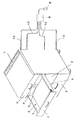
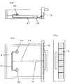
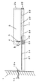
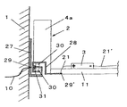
本発明のその他の長所および詳細は以下の図説明を利用してより詳しく説明する。図1は、一実施例における本発明に従って形成された引出しを備えた本発明に係わる家具本体である。図2a、2b、および2cは、押込んだ家具引出の水平平面図と引出した家具引出における水平平面図の概略垂直部における本発明に係わる家具引出の一実施例である。図3a、3bおよび3cは、平面図およびフロントパネルの正面図の概略垂直部における太陽電池供給部を備えたもう1つの実施例である。図4aおよび4bは、内臓された照明を備えた本発明に係わる家具引出のもう1つの実施例であり、図4bは図4a記載の取付枠具の断面図である。図5は、その場合に再充電可能の蓄電池を有する支承された家庭用機器を備えた本発明に係わる家具引出の一実施例である。図6a、6bおよび6cは、垂直縦断面図、平面図およびフロントパネルの正面図における再充電可能の家庭用機器を収容するための太陽電池および保持具を備えた本発明に係わる家具引出のもう1つの実施例である。図7は、電気的駆動モータを備えた本発明に係わる家具引出の一実施例である。図8は、電気的供給が案内レールを介して行われる部分断面図における本発明に係わる家具引出の一実施例である。図9a、9bおよび9cは、押込んだ家具引出における水平平面図と引出した家具引出における水平平面図の概略垂直部における本発明に係わる家具引出の一実施例である。
【0016】
図1に示した家具本体1は、それぞれ後壁の中に再充電可能の蓄電池(再充電可能のバッテリー)を有する4つの引出可能の引出し2を有する。引出側壁(引出枠部4)の中に概略的に図示した照明5(実際上例えば長尺の蛍光管)を設けており、これが透明の部分を介して引出しの内部を照明する。このランプ5の電源は再充電可能のバッテリー3から行われ、前記バッテリーは、すでに述べたように、引出後壁6の中に内臓されている。この再充電可能のバッテリー3を充電するために、引出しを閉じたときに、以下さらに詳しく説明する電気的エネルギーを伝送するための装置が設けられている。このエネルギーは、例えば太陽電池7から家具本体の上側でまたはプラグ8、変圧器9および回線10を介して通常の電力網から取り出すことができる。
【0017】
家具本体の内部ならびに再充電可能のバッテリーとランプ5との間の回線は、詳しく図示しない。前記回線は、スペース的に有利に、好ましくは見えないように敷設することができる。引出しを引出した場合にのみ照明を入れるスイッチも、詳しく図示しない。前記スイッチは、例えば引出後壁に固定し、冷蔵庫扉を開く場合と同様にして照明を入れることができる。太陽電池7もしくは公共の電力網を介した供給は、別法としてまたは同時に設けることができ、詳しく図示しない。電子部品が太陽電池の光が不足する場合に公共の電力網を利用する。それによりエネルギーを節約することができる。しかしまた低電力消費量体の場合は太陽電池単独でも充分とすることができる。
【0018】
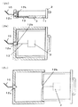
図2a、2bおよび2cに図示した実施例において、再充電可能のバッテリー3は引出底部11の中に内臓されている。電気的エネルギーを伝送するための装置は、この場合に2分割型に形成した誘導結合器12a、12bからなり、これは引出しを閉めたときに電気的エネルギー伝送を可能にし、それによって回線13を介して蓄電池に充電することができる。外部からの電力供給は、回線10を介して、例えば公共の電力網から、変圧器を介してまたは太陽電池から行われる。誘導結合器自体は無接触式の電気的伝送を可能にし、すでに述べたように、例えば電気歯ブラシですでに知られている。前記結合器は、引出しを何度開閉しても全く摩耗が少ない。図2のように引出しを引出したときは、引出しが回線10から分離される。ここに詳しく図示しない消費体、例えばランプ、駆動モータ等々の電力供給は、その場合に充電された蓄電池3を介して行われる。
【0019】
図3a、3bおよび3cに図示した実施例において、同様に引出しの底部11に、太陽電池パネル15の充電調節器14を介して引出しのフロントパネル2aで充電可能である蓄電池3が設けられている。
【0020】
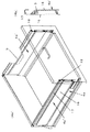
図4aおよび4bに図示した実施例において、取付枠部4a′の中に長尺の蛍光管5が組み込まれており、取付枠部の壁16は、少なくとも引出しの内側で、引出しの内部空間を照明できるようにするため透明に形成してよい。壁16は穿孔されており、その穿孔部分を介して結合されており、上部領域には例えばアルミニウム製の保持部が設けられており、これが通常の引出しレール18の中へ掛釣可能である。全体の取付枠部4a′は本来の引出枠部4aに載置可能であり、上部がレール18で保持される。
【0021】
図4aおよび4bの実施例において、簡略にするために電気的回線、再充電可能の蓄電体ならびに場合によって設けられるスイッチは図示していない。しかしまた、別法として連続的な電力供給は案内レールを介して行ってもよく、これは以下さらに図8を利用して説明する。
【0022】
図5に図示した実施例において、再充電可能の蓄電体はバッテリーの形態で家庭用機器19の中に配設されており、これは引出し2の中に収容することができる。家庭用機器の中の前記の再充電可能のバッテリーの充電は、引出しを閉じたとき誘導結合器12a、12bと保持具20とを介して行われ、これらは差込コンタクトまたは同様に誘導結合器のいずれかとしてよい。引出しを引出したときは、そこで家庭用機器19を簡単に取り出すことができる。
【0023】
図6a、6bおよび6cは、保持具20のための別法の電力供給、すなわち太陽電池パネル15を介した、充電調節器14および保持具20への回線21である。家庭用機器はこの図示においてまさに取り出されている。
【0024】
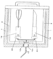
図7は、電気的エネルギーを伝送するための装置が家具本体1から引出し2へ機械的な差込コンタクト12a′、12b′を介して行う実施例であり、これは引出しを閉じたとき自動的に電気的コンタクトを構築する。家具後壁6の中には、さらに再充電可能の蓄電体が充電可能のバッテリー3の形態で内臓されており、これはスイッチ22および回線23を介して引出しの底部11で電気的駆動モータ24に供給する。前記駆動モータは、本体側のレールの歯付棒26に係合し、それによって引出しの駆動を可能にするピニオン25を担持する。本体側の案内レール27と引出し側の案内レール28との間の通常の走行ローラもしくは滑動体は、簡略にするため図示しない。これらは今日の工業規格に相当する。つまり図7に図示した実施例において、自走式に自体駆動される引出しは駆動モータ24の電力供給の邪魔になる可動ケーブルなしに得られる。
【0025】
図8に図示した実施例において、本体側に固定した案内レール27は位置29で供給回線10(正極)と電気的に接触する。引出し2から底部11および側壁4aが片側に図示されている。引出しと接続されて、引出し側の案内レール28、大幅に概略的に図示したローラ、ころ軸受またはすべり軸受30は引出しレール27に対して引出可能である。ここで常時接触している本体側の案内レール27と引出し側の案内レール28との間の電気的コンタクトを構築するために、摺動コンタクト31を設けてあり、これが各引出し位置で特に引出しを閉じている場合にも、引出しの内部とのコンタクトを構築する。接触点29′とケーブル21を介して再充電可能のバッテリー3を充電することができる。これは、もちろんスペース的に有利に引出底部11の中に内臓してもよい。別の極は、回線21′を介して、右側のここに図示しない類似のシステムを介して案内レールに常時接触している。このようなシステムにおいては、もちろんその場合に各引出し位置で引出しにもしくはその中にまたはその横に取付けられた消費体の電気的供給を保証することを可能にするため、再充電可能の蓄電体を省くこともできる。
【0026】
図9a、9bおよび9cに図示した実施例は、再充電可能のバッテリー3の代わりに5つの好ましくは並列に接続したコンデンサ32の配列を引出底部11の中に内臓したことによって、図2a、2bおよび2cに図示した実施例から区別されている。例えば市販されている典型的にセンチメートル範囲の寸法とそれぞれのオーダーに応じて50〜500μFの容量とを有するコンデンサを使用してよい。これらは、例えば典型的な引出しの開時間にわたり光源を駆動するために充分である。
【0027】
【発明の効果】
本発明の家具引出は、上記構成を採ったことにより、家具本体から引出しまでの電気ケーブルの形態で常設させる回線を避けることができる。
【図面の簡単な説明】
【図1】図1は、本発明の引出しを備えた家具本体を示す斜視図である。
【図2】本発明の家具引出の一実施例を示し、2aは押込んだ家具引出の縦断面図であり、2bは押込んだ家具引出の水平平面図であり、2cは引出した家具引出の水平平面図である。
【図3】本発明の家具引出の別の実施例を示し、3aは家具引出の縦断面図であり、3bはその平面図、3cはフロントパネルの正面図である。
【図4】本発明の家具引出のさらに別の実施例を示し、4aは内臓された照明を備えた家具引出の斜視図であり、4bは、その取付枠具の拡大断面図である。
【図5】図5は再充電可能の蓄電池を有する支承された家庭用機器を備えた家具引出の拡大平面図である。
【図6】再充電可能の家庭用機器を収容するための太陽電池および保持具を備えた家具引出を示し、6aはその縦断面図、6bはその平面図、6cはフロントパネルの正面図である。
【図7】図7は電気的駆動モータを備えた本発明に係わる家具引出の縦断面図である。
【図8】図8は電気的供給が案内レールを介して行われる家具引出の部分断面図である。
【図9】本発明の家具引出のさらに別の実施例を示し、9aは押込んだ家具引出の縦断面図、9bはその平面図、9cは引出した家具引出の水平平面図である。
【符号の説明】
1・・・家具本体
2・・・引出し
2a、4a、6・・・引出し壁
3・・・バッテリー
7・・・太陽電池
12a、12b、12a′、12b′・・・蓄電体に電気的エネルギーを伝送するための装置
5、19、24・・・バッ電気的消費体
20・・・保持具
32・・・コンデンサ[0001]
BACKGROUND OF THE INVENTION
The present invention relates to a furniture drawer which can be supported so as to be able to be drawn out in the furniture body, and to a furniture provided with at least one drawable furniture drawer.
[0002]
[Prior art and problems to be solved by the invention]
An object of the present invention is to provide a furniture drawer that can avoid a permanent line in the form of an electrical cable from the furniture body to the drawer.
[0003]
[Means for Solving the Problems]
The furniture drawer of the present invention is for transmitting electrical energy to at least one power storage unit disposed in or next to the drawer in order to avoid a permanent circuit in the form of an electrical cable from the furniture body to the drawer. The apparatus is provided.
[0004]
Using the rechargeable power storage body as described above, it is possible to automatically prepare the supply energy for the drawer or for the electrical equipment built in it, preferably for household equipment, preferably Electric energy is transmitted to charge the storage battery that can be charged only when the drawer is closed. Then, when the drawer is pulled out, the charged power storage body supplies to an electrical consumer such as a lamp or drive motor, or removes household equipment that charges when the drawer in the drawer is closed Can do.
[0005]
In order to realize the device for transmitting electrical energy as described above, a contactless repeater, preferably an inductive coupler or a plug contact, is preferably provided on the rear wall of the drawer, which closes the drawer. When it comes into contact with the main body automatically. The power supply is performed, for example, via a transformer that generates a low-voltage region that is not dangerous to humans in the region drawn from the AC power network that is normally used, preferably at 25 volts or less.
[0006]
The electrical induction repeaters described above are already known per se, for example in electric toothbrushes, and therefore do not need to be described in detail.
[0007]
The rechargeable power storage unit can be incorporated or built in the drawer wall or the drawer bottom, advantageously in terms of space.
[0008]
However, it is also possible to use conventional metal guide rails in the drawer for current transmission, in which case the main body guide rail connected to the power supply is advantageously used as the drawer side guide rail. A sliding contact is provided for connection to the terminal.
[0009]
Cables can be avoided when using such electrical guide rails. In this case, it is possible to continuously supply power into the drawer at each position, so that in this variant of the invention, a rechargeable power storage is also basically unnecessary.
[0010]
Rather, electrical consumers such as lamps or motors can always be supplied directly. Of course, the household equipment inside the drawer having the storage battery can be charged through the electrified guide rail as described above.
[0011]
A particularly preferred embodiment of the invention results from the fact that at least one light source is formed as a light emitting diode (LED). Light emitting diodes combine a compact structure with low power consumption and good luminous efficiency.
[0012]
In addition to supplying from the normal power grid, it is also contemplated to provide solar cells on the drawer or furniture body according to another variant of the invention. Cost-advantageously via a solar cell as described above, it is possible to supply an electrical consumer in the drawer or next to the drawer without the need for connection to a power grid, preferably corresponding to the solar cell A rechargeable power storage unit that is charged via a charge controller is provided.
[0013]
A particularly preferred embodiment of the invention results from the fact that at least one power storage unit is a rechargeable battery. Such a rechargeable battery can be obtained in a number of different embodiments, so that a suitably rechargeable battery can be selected depending on the expected power consumption and the space provided.
[0014]
Another preferred embodiment of the present invention results from the at least one rechargeable battery being a capacitor. Even after long-term use, unlike the case of a storage battery, for example, the memory effect that the storage capacity is reduced does not occur.
[0015]
DETAILED DESCRIPTION OF THE INVENTION
Other advantages and details of the present invention will be described in more detail using the following figure description. FIG. 1 is a furniture body according to the present invention with a drawer formed according to the present invention in one embodiment. 2a, 2b, and 2c are one embodiment of a furniture drawer according to the present invention in a generally vertical portion of a horizontal plan view of a pushed-in furniture drawer and a horizontal plan view of the pulled out furniture drawer. FIGS. 3a, 3b and 3c are another example with a solar cell supply in the schematic vertical portion of the plan view and front view of the front panel. Figures 4a and 4b are another embodiment of a furniture drawer according to the present invention with built-in lighting, and Figure 4b is a cross-sectional view of the mounting frame described in Figure 4a. FIG. 5 is an example of a furniture drawer according to the invention with a supported household appliance having a rechargeable storage battery in that case. Figures 6a, 6b and 6c show a furniture drawer according to the invention with a solar cell and a holder for housing rechargeable household equipment in a vertical longitudinal section, a plan view and a front view of the front panel. One example. FIG. 7 shows an embodiment of the furniture drawer according to the present invention provided with an electric drive motor. FIG. 8 shows an embodiment of the furniture drawer according to the present invention in a partial cross-sectional view in which the electrical supply is performed via a guide rail. FIGS. 9a, 9b and 9c show an embodiment of the furniture drawer according to the present invention in a generally vertical section of the horizontal plan view of the pushed-in furniture drawer and the horizontal plan view of the pulled-out furniture drawer.
[0016]
The
[0017]
The interior of the furniture body and the line between the rechargeable battery and the lamp 5 are not shown in detail. The line can be laid out in an advantageous manner, preferably invisible. A switch that turns on the light only when the drawer is pulled out is not shown in detail. The switch can be fixed, for example, on the wall after the drawer, and can be turned on in the same manner as when the refrigerator door is opened. Supply via
[0018]
In the embodiment illustrated in FIGS. 2 a, 2 b and 2 c, the
[0019]
3a, 3b and 3c, similarly, a
[0020]
In the embodiment shown in FIGS. 4a and 4b, a long fluorescent tube 5 is incorporated in the mounting
[0021]
In the embodiment of FIGS. 4a and 4b, for the sake of simplicity, the electrical lines, rechargeable power storage units and optionally provided switches are not shown. However, alternatively, continuous power supply may be provided via a guide rail, which will be further explained with reference to FIG.
[0022]
In the embodiment illustrated in FIG. 5, the rechargeable power storage unit is arranged in the
[0023]
FIGS. 6 a, 6 b and 6 c show an alternative power supply for the
[0024]
FIG. 7 shows an embodiment in which the device for transmitting electrical energy is carried out from the
[0025]
In the embodiment shown in FIG. 8, the
[0026]
The embodiment illustrated in FIGS. 9 a, 9 b and 9 c, instead of the
[0027]
【The invention's effect】
Since the furniture drawer of the present invention adopts the above-described configuration, it is possible to avoid a circuit that is permanently installed in the form of an electric cable from the furniture body to the drawer.
[Brief description of the drawings]
FIG. 1 is a perspective view showing a furniture body provided with a drawer according to the present invention.
FIG. 2 shows an embodiment of a furniture drawer according to the present invention. 2a is a longitudinal sectional view of the pushed-in furniture drawer, 2b is a horizontal plan view of the pushed-out furniture drawer, and 2c is a drawn-out furniture drawer. FIG.
FIG. 3 shows another embodiment of the furniture drawer according to the present invention, in which 3a is a longitudinal sectional view of the furniture drawer, 3b is a plan view thereof, and 3c is a front view of the front panel.
FIG. 4 shows still another embodiment of the furniture drawer according to the present invention. 4a is a perspective view of the furniture drawer with a built-in illumination, and 4b is an enlarged sectional view of the mounting frame.
FIG. 5 is an enlarged plan view of a furniture drawer with supported home appliances having rechargeable storage batteries.
6 shows a furniture drawer with solar cells and holders for housing rechargeable household equipment, 6a being a longitudinal section, 6b being a plan view thereof, and 6c being a front view of a front panel. is there.
FIG. 7 is a longitudinal sectional view of a furniture drawer according to the present invention provided with an electric drive motor.
FIG. 8 is a partial sectional view of a furniture drawer in which electrical supply is performed via a guide rail.
FIG. 9 shows still another embodiment of the furniture drawer according to the present invention, wherein 9a is a longitudinal sectional view of the pushed-out furniture drawer, 9b is a plan view thereof, and 9c is a horizontal plan view of the drawer of the furniture drawer.
[Explanation of symbols]
DESCRIPTION OF
Claims (12)
Applications Claiming Priority (2)
| Application Number | Priority Date | Filing Date | Title |
|---|---|---|---|
| AT0078501A AT413185B (en) | 2001-05-17 | 2001-05-17 | FURNITURE DRAWER |
| AT785/2001 | 2001-05-17 |
Publications (2)
| Publication Number | Publication Date |
|---|---|
| JP2003000372A JP2003000372A (en) | 2003-01-07 |
| JP4258702B2 true JP4258702B2 (en) | 2009-04-30 |
Family
ID=3680907
Family Applications (1)
| Application Number | Title | Priority Date | Filing Date |
|---|---|---|---|
| JP2002141447A Expired - Fee Related JP4258702B2 (en) | 2001-05-17 | 2002-05-16 | Furniture drawer |
Country Status (8)
| Country | Link |
|---|---|
| US (1) | US20020171335A1 (en) |
| EP (1) | EP1260158B2 (en) |
| JP (1) | JP4258702B2 (en) |
| CN (1) | CN1270654C (en) |
| AT (2) | AT413185B (en) |
| BR (1) | BR0201850B1 (en) |
| DE (1) | DE50204823D1 (en) |
| ES (1) | ES2251539T5 (en) |
Families Citing this family (94)
| Publication number | Priority date | Publication date | Assignee | Title |
|---|---|---|---|---|
| US7468418B2 (en) | 2003-04-29 | 2008-12-23 | Avi Biopharma., Inc. | Compositions for enhancing transport of molecules into cells |
| AT503998B1 (en) * | 2003-05-19 | 2010-07-15 | Blum Gmbh Julius | METHOD FOR DRIVING A MOVABLE FURNITURE PART |
| JP4515126B2 (en) * | 2004-03-26 | 2010-07-28 | 大日本印刷株式会社 | Storage case with drawer |
| FR2868921B3 (en) * | 2004-04-14 | 2006-12-01 | Jean Marie Peterle | WORK FURNITURE FOR VIDEO-PROJECTOR. |
| US7784888B2 (en) * | 2004-10-26 | 2010-08-31 | Lg Electronics Inc. | Refrigerator |
| KR100700777B1 (en) * | 2005-03-02 | 2007-03-27 | 엘지전자 주식회사 | Refrigerating machine and basket operating apparatus |
| JP4581917B2 (en) * | 2005-08-26 | 2010-11-17 | パナソニック電工株式会社 | Bathroom vanity |
| EP1769701A1 (en) * | 2005-10-03 | 2007-04-04 | SALM SA Société par actions simplifiée | Furniture provided with electrical conection means |
| FR2891446B1 (en) * | 2005-10-03 | 2010-08-13 | Salm Sa | FURNITURE AND MEANS FOR ELECTRICAL CONNECTION FOR SAID FURNITURE |
| DE202005016829U1 (en) | 2005-10-27 | 2006-01-05 | MEPLA-WERKE LAUTENSCHLäGER GMBH & CO. KG | Lighting device for furniture |
| DE102006016102B4 (en) * | 2006-04-04 | 2019-01-31 | Grass Gmbh | Furniture with at least two motor furniture movable relative to a first furniture part further furniture parts |
| US20070247037A1 (en) * | 2006-04-24 | 2007-10-25 | Schenker David A | Storage drawer assembly with power capability and modular drawer arrangement |
| DE202006007151U1 (en) * | 2006-05-04 | 2007-09-20 | Hettich Strothmann Gmbh & Co. Kg | Furniture |
| WO2007139918A2 (en) * | 2006-05-26 | 2007-12-06 | Waterloo Industries, Inc. | Modular power for chests and cabinets |
| DE202006011039U1 (en) * | 2006-07-14 | 2007-12-06 | Alfit Ag | Device for moving furniture parts and furniture that are movable relative to one another |
| DE202006014405U1 (en) * | 2006-09-15 | 2008-01-31 | Paul Hettich Gmbh & Co. Kg | Cupboard furniture with at least one drawer |
| US20080170355A1 (en) * | 2007-01-16 | 2008-07-17 | Anna Kyriakides | Container for multiple household electronic charging compartment |
| US7884502B2 (en) * | 2007-08-09 | 2011-02-08 | Zerobase Energy, Llc | Deployable power supply system |
| DE202008000195U1 (en) * | 2008-01-05 | 2008-04-17 | Häcker Küchen GmbH & Co. KG | Kitchen furniture with drawer and lighting |
| DE202008003346U1 (en) * | 2008-03-07 | 2009-07-23 | Grass Gmbh | Furniture part and device for generating a lighting effect on a relative to a fixed furniture part movable furniture part |
| EP2283292A1 (en) * | 2008-03-26 | 2011-02-16 | LG Electronics Inc. | System and method for driving a drawer in a refrigerator |
| KR101441133B1 (en) * | 2008-03-26 | 2014-09-17 | 엘지전자 주식회사 | Controlling method for driving drawer of refrigerator |
| US8217613B2 (en) | 2008-03-26 | 2012-07-10 | Lg Electronics Inc. | System and method for driving a drawer of a refrigerator and refrigerator employing same |
| KR101380557B1 (en) * | 2008-03-26 | 2014-04-01 | 엘지전자 주식회사 | System and method for driving a drawer in a refrigerator |
| EP3553434B1 (en) * | 2008-03-26 | 2021-07-28 | Lg Electronics Inc. | Method for driving a drawer in a refrigerator |
| CN101981398B (en) * | 2008-03-26 | 2013-03-27 | Lg电子株式会社 | Refrigerator, system and method for driving a drawer of the refrigerator |
| CN101981394A (en) * | 2008-03-26 | 2011-02-23 | Lg电子株式会社 | Refrigerator |
| WO2009157017A2 (en) * | 2008-06-04 | 2009-12-30 | Gosakan Aravamudan | Furniture lighting |
| JP4597221B2 (en) * | 2008-06-04 | 2010-12-15 | シャープ株式会社 | Drawer type cooking device |
| JP4597222B2 (en) * | 2008-06-04 | 2010-12-15 | シャープ株式会社 | Drawer type cooking device |
| US8291816B2 (en) * | 2008-06-04 | 2012-10-23 | Sharp Kabushiki Kaisha | Drawer type cooking device |
| US20100033015A1 (en) * | 2008-08-07 | 2010-02-11 | Techstream Control Systems, Inc | Unitized Electric Generator and Storage System - Combined Hydro Turbine and Solar Powered Electrical Storage System |
| DE202008011547U1 (en) * | 2008-08-29 | 2010-01-07 | Paul Hettich Gmbh & Co. Kg | drawer |
| AT507241B1 (en) * | 2008-09-03 | 2013-05-15 | Blum Gmbh Julius | FURNITURE WITH DRAWER AND POWER CONSUMER |
| DE202008015222U1 (en) * | 2008-11-17 | 2010-04-01 | Grass Gmbh | Device for influencing the movement of a movable furniture part and furniture |
| KR101592573B1 (en) * | 2009-03-20 | 2016-02-05 | 엘지전자 주식회사 | A refrigerator |
| KR101592571B1 (en) * | 2009-03-20 | 2016-02-05 | 엘지전자 주식회사 | A refrigerator for controlling refrigerator |
| KR101592574B1 (en) * | 2009-03-20 | 2016-02-05 | 엘지전자 주식회사 | A refrigerator for controlling refrigerator |
| KR101592572B1 (en) * | 2009-03-20 | 2016-02-05 | 엘지전자 주식회사 | A refrigerator for controlling refrigerator |
| KR101592575B1 (en) * | 2009-03-20 | 2016-02-05 | 엘지전자 주식회사 | Refrigerator |
| WO2010132578A1 (en) | 2009-05-12 | 2010-11-18 | Kimball International, Inc. | Furniture with wireless power |
| US9124308B2 (en) | 2009-05-12 | 2015-09-01 | Kimball International, Inc. | Furniture with wireless power |
| DE202009004882U1 (en) * | 2009-06-03 | 2010-10-21 | Paul Hettich Gmbh & Co. Kg | Device for transmitting electrical energy |
| US8480191B1 (en) * | 2009-06-12 | 2013-07-09 | Fredricks Design, Inc. | Storage apparatus |
| US20110109211A1 (en) * | 2009-11-12 | 2011-05-12 | Bob Kirkeby | Furniture Product with Power Port Feature |
| ITVI20100098A1 (en) * | 2010-04-08 | 2011-10-09 | Paolo Pietro Meneghini | DRAWER WITH DRAWER AND INTERIOR LIGHTING DEVICE |
| US9307888B2 (en) | 2011-11-23 | 2016-04-12 | Whirlpool Corporation | System for charging a power supply in a closure element of a household appliance |
| US10004379B2 (en) | 2011-11-23 | 2018-06-26 | Whirlpool Corporation | Dishwasher with transforming door |
| CN102673482A (en) * | 2012-05-30 | 2012-09-19 | 郑州日产汽车有限公司 | Vehicular multifunctional container box |
| WO2014065695A1 (en) * | 2012-10-22 | 2014-05-01 | Общество С Ограниченной Ответственностью Компания "Норкпалм" | Lighted drawer, lighting device and current collector |
| RU2519910C1 (en) * | 2012-11-09 | 2014-06-20 | Общество С Ограниченной Ответственностью Компания "Норкпалм" | Drawer with illumination, illumination device and current collector |
| DE102013103819A1 (en) * | 2013-04-16 | 2014-10-16 | Miele & Cie. Kg | cooling unit |
| US9572475B2 (en) * | 2013-04-29 | 2017-02-21 | Whirlpool Corporation | Appliance with closure element having an operative device |
| US9585474B2 (en) | 2013-07-17 | 2017-03-07 | Whirlpool Corporation | Traveling harness system |
| CN103465242A (en) * | 2013-08-28 | 2013-12-25 | 昆山凯恒五金配件有限公司 | Push-pull type lighting-tool cabinet |
| DE102013109304A1 (en) * | 2013-08-28 | 2015-03-05 | Paul Hettich Gmbh & Co. Kg | Fitting a piece of furniture or household appliance and furniture or household appliance |
| CA2865739C (en) | 2013-09-30 | 2018-12-04 | Norman R. Byrne | Wireless power for portable articles |
| CA2865457C (en) | 2013-09-30 | 2019-01-22 | Norman R. Byrne | Articles with electrical charging surfaces |
| DE202013104447U1 (en) * | 2013-09-30 | 2015-01-08 | Halemeier Gmbh & Co. Kg | Circuit for supplying power to a luminaire on a movable furniture part |
| US9845986B2 (en) | 2014-02-24 | 2017-12-19 | Whirlpool Corporation | Lighting units for refrigerator drawers and baskets |
| GB2528963B (en) | 2014-08-07 | 2018-07-25 | Artform Int Ltd | Product display shelf, system and method |
| JP6566540B2 (en) * | 2014-10-31 | 2019-08-28 | 株式会社オカムラ | Office storage |
| US10181735B2 (en) | 2015-03-11 | 2019-01-15 | Norman R. Byrne | Portable electrical power unit |
| JP6629517B2 (en) * | 2015-03-27 | 2020-01-15 | 株式会社オカムラ | Furniture |
| BE1023668B1 (en) * | 2015-12-09 | 2017-06-12 | Ets J. Stillemans N.V. | FURNITURE WITH ELECTRIC CIRCUIT |
| WO2017127456A1 (en) | 2016-01-18 | 2017-07-27 | Dci Marketing, Inc. Dba Dci - Artform | Sensors, devices, adapters and mating structures for merchandisers and related methods |
| MX2017003091A (en) | 2016-03-11 | 2018-08-15 | Norman R Byrne | Furniture-mounted charging station. |
| US10588427B2 (en) | 2016-03-23 | 2020-03-17 | Retail Space Solutions Llc | Low product indicator for self facing merchandiser and related methods |
| US10576000B2 (en) | 2016-04-08 | 2020-03-03 | 19Labs Inc. | Systems and methods for supplying power to removable storage compartments |
| US10988940B2 (en) | 2016-06-03 | 2021-04-27 | Norman R. Byrne | Surface-mounted resonators for wireless power |
| US10253527B2 (en) | 2016-06-10 | 2019-04-09 | Steelcase Inc. | Smart locker |
| US10952548B2 (en) | 2016-10-18 | 2021-03-23 | Retail Space Solutions Llc | Illuminated merchandiser, retrofit kit and related methods |
| MX2017017070A (en) | 2016-12-28 | 2018-11-09 | Norman R Byrne | Storage tote with electrical outlets. |
| AU2018201874B2 (en) * | 2017-03-17 | 2023-08-24 | Miles, Shane Robert MR | Drawers and components for drawers |
| US10283952B2 (en) | 2017-06-22 | 2019-05-07 | Bretford Manufacturing, Inc. | Rapidly deployable floor power system |
| MX2018008989A (en) | 2017-07-24 | 2019-02-08 | R Byrne Norman | Furniture-mounted electrical charging station. |
| US10306993B1 (en) * | 2018-01-23 | 2019-06-04 | 2 Way Chaise LLC | Two way chaise lounge with solar charging station |
| US10976047B2 (en) | 2018-08-23 | 2021-04-13 | Snap-On Incorporated | Illumination for storage units |
| US10669768B2 (en) | 2018-09-28 | 2020-06-02 | Toyota Research Institute, Inc. | Robotic power delivery |
| IT201800009298A1 (en) * | 2018-10-09 | 2020-04-09 | Boccolini Srl | DRAWER ASSEMBLY FOR ILLUMINATED FURNITURE AND SIDE SUPPORT AND GUIDE |
| US11293630B2 (en) | 2018-11-21 | 2022-04-05 | Snap-On Incorporated | Interactive tool storage system |
| DE202019101563U1 (en) * | 2019-03-19 | 2020-06-22 | Grass Gmbh | Device with a drawer rail and a lighting device, drawer and furniture |
| US11047566B2 (en) | 2019-06-28 | 2021-06-29 | Snap-On Incorporated | Lighting assembly for storage units |
| DE202020100078U1 (en) | 2020-01-09 | 2021-04-12 | Grass Gmbh | Busbar |
| CN112092735B (en) * | 2020-07-31 | 2022-02-11 | 东风延锋汽车饰件系统有限公司 | Drawer type storage box with hidden buckle for automobile cab |
| AT524181B1 (en) | 2020-09-08 | 2024-04-15 | Blum Gmbh Julius | Device for guiding a power cable |
| IT202100004862A1 (en) | 2021-03-02 | 2022-09-02 | Osram Gmbh | DRAWER STRUCTURE WITH RADIATION SOURCES |
| DE102021204147A1 (en) | 2021-04-27 | 2022-10-27 | BSH Hausgeräte GmbH | Charging drawer and temperature control system |
| AT17650U1 (en) * | 2021-04-30 | 2022-10-15 | Blum Gmbh Julius | Method of lighting a piece of furniture |
| DE102021125987A1 (en) | 2021-10-07 | 2023-04-13 | Grass Gmbh | Furniture body with an energy transmission device and a movable furniture part with an energy absorbing element |
| DE102021214591A1 (en) | 2021-12-17 | 2023-06-22 | Grass Gmbh | Drive system for driving at least one movable furniture part |
| BE1030071B1 (en) * | 2021-12-22 | 2023-07-17 | Miele & Cie | Household appliance and method of operating a household appliance |
| AT526800A1 (en) * | 2022-12-23 | 2024-07-15 | Blum Gmbh Julius | Arrangement comprising a fixed furniture part, a movable furniture part, a guide device, an electric drive device and a lighting means |
| AT526791B1 (en) * | 2023-02-24 | 2024-07-15 | Blum Gmbh Julius | Power supply device for supplying power to a pull-out element |
Family Cites Families (33)
| Publication number | Priority date | Publication date | Assignee | Title |
|---|---|---|---|---|
| US1497728A (en) * | 1924-06-17 | Ravthtq kjeuesh | ||
| US1532935A (en) * | 1923-10-04 | 1925-04-07 | Patton John Shelton | Device for electrically illuminating card cabinets |
| US2456867A (en) * | 1946-01-26 | 1948-12-21 | Costa Bartholomew Da | Bed table |
| US2875321A (en) * | 1955-08-04 | 1959-02-24 | Joseph K Doliva | Television cabinet lighting fixture |
| US3028209A (en) * | 1957-07-25 | 1962-04-03 | Whirlpool Co | Movable kitchen units and control means therefor |
| US4172967A (en) * | 1975-10-08 | 1979-10-30 | James John Porter | Automatic answering device for use in live speech communication and circuit components thereof |
| US4071747A (en) * | 1976-09-27 | 1978-01-31 | Pantanella Anthony C | Drawer illuminating device |
| US4095859A (en) * | 1977-01-05 | 1978-06-20 | Baylor College Of Medicine | Portable eye examination system cart |
| US4178626A (en) † | 1978-04-17 | 1979-12-11 | Prince Corporation | Drawer light |
| DE3106068A1 (en) † | 1981-02-19 | 1982-09-09 | Binz Gmbh & Co, 7073 Lorch | "CABINET UNIT WITH ONE OR SEVERAL DRAWERS FOR RECEIVING MEDICAL DEVICES" |
| US4442478A (en) * | 1982-02-19 | 1984-04-10 | Stansbury Benjamin H | Automatically actuated enclosure light |
| DE3303727A1 (en) * | 1983-02-04 | 1984-08-09 | Gluma GmbH Elektrotechnische Erzeugnisse, 7887 Laufenburg | Device for transferring electrical energy |
| DE3641354A1 (en) * | 1986-12-03 | 1988-06-16 | Horst Muhlack | EXHIBITION SHOWCASE |
| DE3712530A1 (en) * | 1987-04-13 | 1988-11-03 | Fischer Artur Werke Gmbh | STORAGE CONTAINER WITH DRAWER ELEMENT |
| US5246285A (en) * | 1991-04-11 | 1993-09-21 | Loren Redburn | Automatic interior lighting device for drawers, cabinets and the like |
| JP2753658B2 (en) * | 1991-05-15 | 1998-05-20 | 象印マホービン株式会社 | Fully automatic rice cooker |
| JPH05199666A (en) † | 1992-01-14 | 1993-08-06 | Seiko Instr Inc | Drawer type charger |
| US5276310A (en) * | 1992-02-28 | 1994-01-04 | William Schmidt | Electrically heated toolbox |
| JPH06205711A (en) * | 1992-10-05 | 1994-07-26 | Yasuo Isobe | Device making object in drawer discernible with illuminant |
| US5399007A (en) * | 1993-04-15 | 1995-03-21 | Reliance Medical Products, Inc. | Medical treatment cabinet |
| DE4327379C2 (en) * | 1993-08-14 | 1995-08-31 | Gehring Einbaubaeder Gmbh | Multi-part mirror cabinet |
| JP2767089B2 (en) * | 1993-12-27 | 1998-06-18 | リンナイ株式会社 | Cabinet type rice cooker |
| DE4425641A1 (en) * | 1994-07-20 | 1995-02-02 | Rosa Schaetzler | Variable insulin cooling box in pocket format |
| BE1008811A3 (en) * | 1994-10-25 | 1996-08-06 | Rothmans Tobacco Company B V | DEVICE FOR EASE OF CHARGE IN CABINETS for the display of ARTICLES. |
| US5645340A (en) * | 1995-06-19 | 1997-07-08 | Colton; Orren L. | Flashlight replacement for vehicle ashtray |
| DE19540057C1 (en) * | 1995-10-27 | 1996-08-01 | Arnold L & C | Combined bed and night table for use in hospitals |
| US5664874A (en) * | 1995-12-29 | 1997-09-09 | Winterer; Allen G. | Barricade warning light |
| US5772291A (en) * | 1996-02-16 | 1998-06-30 | Mosinee Paper Corporation | Hands-free paper towel dispensers |
| DE19705779C1 (en) * | 1997-02-14 | 1998-05-20 | Bosch Siemens Hausgeraete | Switch-off component for mains connection conduit used with household appliances e.g. cooker |
| IT1297984B1 (en) * | 1997-09-30 | 1999-12-20 | Veloservice S R L | AUTOMATIC SERVICE STATION FOR MOBILE PHONE |
| SE511880C3 (en) * | 1998-03-10 | 2000-01-31 | Aasa Palmqvist | Device for exposure of objects |
| US6169655B1 (en) † | 1998-04-30 | 2001-01-02 | Hewlett-Packard Company | Computer docking drawer |
| DE20018317U1 (en) † | 2000-10-26 | 2001-02-22 | Doerrer, Christoph, Dipl.-Ing., 64293 Darmstadt | Business car |
-
2001
- 2001-05-17 AT AT0078501A patent/AT413185B/en not_active IP Right Cessation
-
2002
- 2002-04-10 DE DE50204823T patent/DE50204823D1/en not_active Expired - Lifetime
- 2002-04-10 ES ES02007955T patent/ES2251539T5/en not_active Expired - Lifetime
- 2002-04-10 EP EP02007955A patent/EP1260158B2/en not_active Expired - Lifetime
- 2002-04-10 AT AT02007955T patent/ATE308903T1/en active
- 2002-05-15 US US10/144,743 patent/US20020171335A1/en not_active Abandoned
- 2002-05-16 CN CNB021197679A patent/CN1270654C/en not_active Expired - Fee Related
- 2002-05-16 BR BRPI0201850-0A patent/BR0201850B1/en not_active IP Right Cessation
- 2002-05-16 JP JP2002141447A patent/JP4258702B2/en not_active Expired - Fee Related
Also Published As
| Publication number | Publication date |
|---|---|
| EP1260158A3 (en) | 2003-04-23 |
| US20020171335A1 (en) | 2002-11-21 |
| EP1260158B1 (en) | 2005-11-09 |
| EP1260158A2 (en) | 2002-11-27 |
| CN1386458A (en) | 2002-12-25 |
| JP2003000372A (en) | 2003-01-07 |
| EP1260158B2 (en) | 2008-08-13 |
| ES2251539T5 (en) | 2009-03-01 |
| CN1270654C (en) | 2006-08-23 |
| DE50204823D1 (en) | 2005-12-15 |
| ATA7852001A (en) | 2005-05-15 |
| AT413185B (en) | 2005-12-15 |
| BR0201850A (en) | 2003-01-07 |
| ATE308903T1 (en) | 2005-11-15 |
| ES2251539T3 (en) | 2006-05-01 |
| BR0201850B1 (en) | 2011-11-29 |
Similar Documents
| Publication | Publication Date | Title |
|---|---|---|
| JP4258702B2 (en) | Furniture drawer | |
| MX2008015040A (en) | Modular power for chests and cabinets. | |
| CN101150018B (en) | Trigger switch | |
| US20060193126A1 (en) | Solar-powered enclosure | |
| MX2008011619A (en) | Refrigerator with plug-in power supply. | |
| WO2006030432A1 (en) | An illumination unit employing a led or a fluorescent lamp for normal and emergency operation | |
| US20140140040A1 (en) | Energizing system of removable components provided with electric-electronic devices and electric driving method for devices disposed in removable components | |
| CN115001127A (en) | Outdoor portable modularized energy storage power supply and outdoor electrical appliance | |
| US5893627A (en) | Automatic low voltage lighting system for cabinets and closets | |
| US7626283B1 (en) | Alternative alternating current power supply and method of its use | |
| CN208832833U (en) | The Modular refrigerator of function combination | |
| CN101225935A (en) | Combined solar lighting apparatus | |
| ES2926048T3 (en) | Extraction guide for mobile drawer elements related to a furniture or appliance frame and furniture or appliance | |
| CN213585196U (en) | Charger with power-off switch mechanism | |
| CN210350453U (en) | Outdoor waterproof switch cabinet | |
| CN211242370U (en) | Embedded structure multifunctional cabinet | |
| CN210454623U (en) | Inside power consumption control circuit of car as a house | |
| US7227282B1 (en) | Alternative alternating current power supply | |
| CN210568052U (en) | LED lighting device for household storage and movement | |
| JP6629517B2 (en) | Furniture | |
| CN216089574U (en) | Wireless charging and wired charging of cell-phone add tertiary light response bedside cupboard of transferring of intelligence | |
| JP3105775U (en) | Mobile charger | |
| CN221282875U (en) | Integrated battery equipment | |
| CN109546671B (en) | Intelligent power supply | |
| KR102008126B1 (en) | Multi-electrical conversion device |
Legal Events
| Date | Code | Title | Description |
|---|---|---|---|
| A521 | Request for written amendment filed |
Free format text: JAPANESE INTERMEDIATE CODE: A523 Effective date: 20020801 |
|
| A621 | Written request for application examination |
Free format text: JAPANESE INTERMEDIATE CODE: A621 Effective date: 20050511 |
|
| A131 | Notification of reasons for refusal |
Free format text: JAPANESE INTERMEDIATE CODE: A131 Effective date: 20080310 |
|
| A601 | Written request for extension of time |
Free format text: JAPANESE INTERMEDIATE CODE: A601 Effective date: 20080530 |
|
| RD02 | Notification of acceptance of power of attorney |
Free format text: JAPANESE INTERMEDIATE CODE: A7422 Effective date: 20080530 |
|
| A602 | Written permission of extension of time |
Free format text: JAPANESE INTERMEDIATE CODE: A602 Effective date: 20080606 |
|
| A521 | Request for written amendment filed |
Free format text: JAPANESE INTERMEDIATE CODE: A523 Effective date: 20080703 |
|
| RD02 | Notification of acceptance of power of attorney |
Free format text: JAPANESE INTERMEDIATE CODE: A7422 Effective date: 20080703 |
|
| A521 | Request for written amendment filed |
Free format text: JAPANESE INTERMEDIATE CODE: A523 Effective date: 20080703 |
|
| TRDD | Decision of grant or rejection written | ||
| A01 | Written decision to grant a patent or to grant a registration (utility model) |
Free format text: JAPANESE INTERMEDIATE CODE: A01 Effective date: 20090106 |
|
| A01 | Written decision to grant a patent or to grant a registration (utility model) |
Free format text: JAPANESE INTERMEDIATE CODE: A01 |
|
| A61 | First payment of annual fees (during grant procedure) |
Free format text: JAPANESE INTERMEDIATE CODE: A61 Effective date: 20090128 |
|
| FPAY | Renewal fee payment (event date is renewal date of database) |
Free format text: PAYMENT UNTIL: 20120220 Year of fee payment: 3 |
|
| R150 | Certificate of patent or registration of utility model |
Free format text: JAPANESE INTERMEDIATE CODE: R150 |
|
| FPAY | Renewal fee payment (event date is renewal date of database) |
Free format text: PAYMENT UNTIL: 20130220 Year of fee payment: 4 |
|
| FPAY | Renewal fee payment (event date is renewal date of database) |
Free format text: PAYMENT UNTIL: 20130220 Year of fee payment: 4 |
|
| FPAY | Renewal fee payment (event date is renewal date of database) |
Free format text: PAYMENT UNTIL: 20140220 Year of fee payment: 5 |
|
| R250 | Receipt of annual fees |
Free format text: JAPANESE INTERMEDIATE CODE: R250 |
|
| R250 | Receipt of annual fees |
Free format text: JAPANESE INTERMEDIATE CODE: R250 |
|
| R250 | Receipt of annual fees |
Free format text: JAPANESE INTERMEDIATE CODE: R250 |
|
| LAPS | Cancellation because of no payment of annual fees |