JP4257601B2 - Vehicle door opening and closing device - Google Patents
Vehicle door opening and closing device Download PDFInfo
- Publication number
- JP4257601B2 JP4257601B2 JP2004186429A JP2004186429A JP4257601B2 JP 4257601 B2 JP4257601 B2 JP 4257601B2 JP 2004186429 A JP2004186429 A JP 2004186429A JP 2004186429 A JP2004186429 A JP 2004186429A JP 4257601 B2 JP4257601 B2 JP 4257601B2
- Authority
- JP
- Japan
- Prior art keywords
- vehicle
- door
- user
- light emitting
- door handle
- Prior art date
- Legal status (The legal status is an assumption and is not a legal conclusion. Google has not performed a legal analysis and makes no representation as to the accuracy of the status listed.)
- Expired - Fee Related
Links
Images
Classifications
-
- G—PHYSICS
- G07—CHECKING-DEVICES
- G07C—TIME OR ATTENDANCE REGISTERS; REGISTERING OR INDICATING THE WORKING OF MACHINES; GENERATING RANDOM NUMBERS; VOTING OR LOTTERY APPARATUS; ARRANGEMENTS, SYSTEMS OR APPARATUS FOR CHECKING NOT PROVIDED FOR ELSEWHERE
- G07C9/00—Individual registration on entry or exit
- G07C9/00174—Electronically operated locks; Circuits therefor; Nonmechanical keys therefor, e.g. passive or active electrical keys or other data carriers without mechanical keys
- G07C9/00309—Electronically operated locks; Circuits therefor; Nonmechanical keys therefor, e.g. passive or active electrical keys or other data carriers without mechanical keys operated with bidirectional data transmission between data carrier and locks
-
- B—PERFORMING OPERATIONS; TRANSPORTING
- B60—VEHICLES IN GENERAL
- B60Q—ARRANGEMENT OF SIGNALLING OR LIGHTING DEVICES, THE MOUNTING OR SUPPORTING THEREOF OR CIRCUITS THEREFOR, FOR VEHICLES IN GENERAL
- B60Q1/00—Arrangement of optical signalling or lighting devices, the mounting or supporting thereof or circuits therefor
- B60Q1/26—Arrangement of optical signalling or lighting devices, the mounting or supporting thereof or circuits therefor the devices being primarily intended to indicate the vehicle, or parts thereof, or to give signals, to other traffic
- B60Q1/2661—Arrangement of optical signalling or lighting devices, the mounting or supporting thereof or circuits therefor the devices being primarily intended to indicate the vehicle, or parts thereof, or to give signals, to other traffic mounted on parts having other functions
- B60Q1/2669—Arrangement of optical signalling or lighting devices, the mounting or supporting thereof or circuits therefor the devices being primarily intended to indicate the vehicle, or parts thereof, or to give signals, to other traffic mounted on parts having other functions on door or boot handles
-
- B—PERFORMING OPERATIONS; TRANSPORTING
- B60—VEHICLES IN GENERAL
- B60R—VEHICLES, VEHICLE FITTINGS, OR VEHICLE PARTS, NOT OTHERWISE PROVIDED FOR
- B60R25/00—Fittings or systems for preventing or indicating unauthorised use or theft of vehicles
- B60R25/20—Means to switch the anti-theft system on or off
- B60R25/2009—Antitheft state indicator
-
- B—PERFORMING OPERATIONS; TRANSPORTING
- B60—VEHICLES IN GENERAL
- B60R—VEHICLES, VEHICLE FITTINGS, OR VEHICLE PARTS, NOT OTHERWISE PROVIDED FOR
- B60R25/00—Fittings or systems for preventing or indicating unauthorised use or theft of vehicles
- B60R25/20—Means to switch the anti-theft system on or off
- B60R25/24—Means to switch the anti-theft system on or off using electronic identifiers containing a code not memorised by the user
- B60R25/246—Means to switch the anti-theft system on or off using electronic identifiers containing a code not memorised by the user characterised by the challenge triggering
-
- E—FIXED CONSTRUCTIONS
- E05—LOCKS; KEYS; WINDOW OR DOOR FITTINGS; SAFES
- E05B—LOCKS; ACCESSORIES THEREFOR; HANDCUFFS
- E05B81/00—Power-actuated vehicle locks
- E05B81/54—Electrical circuits
- E05B81/64—Monitoring or sensing, e.g. by using switches or sensors
- E05B81/76—Detection of handle operation; Detection of a user approaching a handle; Electrical switching actions performed by door handles
- E05B81/78—Detection of handle operation; Detection of a user approaching a handle; Electrical switching actions performed by door handles as part of a hands-free locking or unlocking operation
-
- E—FIXED CONSTRUCTIONS
- E05—LOCKS; KEYS; WINDOW OR DOOR FITTINGS; SAFES
- E05B—LOCKS; ACCESSORIES THEREFOR; HANDCUFFS
- E05B17/00—Accessories in connection with locks
- E05B17/10—Illuminating devices on or for locks or keys; Transparent or translucent lock parts; Indicator lights
-
- G—PHYSICS
- G07—CHECKING-DEVICES
- G07C—TIME OR ATTENDANCE REGISTERS; REGISTERING OR INDICATING THE WORKING OF MACHINES; GENERATING RANDOM NUMBERS; VOTING OR LOTTERY APPARATUS; ARRANGEMENTS, SYSTEMS OR APPARATUS FOR CHECKING NOT PROVIDED FOR ELSEWHERE
- G07C9/00—Individual registration on entry or exit
- G07C9/00174—Electronically operated locks; Circuits therefor; Nonmechanical keys therefor, e.g. passive or active electrical keys or other data carriers without mechanical keys
- G07C9/00309—Electronically operated locks; Circuits therefor; Nonmechanical keys therefor, e.g. passive or active electrical keys or other data carriers without mechanical keys operated with bidirectional data transmission between data carrier and locks
- G07C2009/00365—Electronically operated locks; Circuits therefor; Nonmechanical keys therefor, e.g. passive or active electrical keys or other data carriers without mechanical keys operated with bidirectional data transmission between data carrier and locks in combination with a wake-up circuit
- G07C2009/00373—Electronically operated locks; Circuits therefor; Nonmechanical keys therefor, e.g. passive or active electrical keys or other data carriers without mechanical keys operated with bidirectional data transmission between data carrier and locks in combination with a wake-up circuit whereby the wake-up circuit is situated in the lock
-
- G—PHYSICS
- G07—CHECKING-DEVICES
- G07C—TIME OR ATTENDANCE REGISTERS; REGISTERING OR INDICATING THE WORKING OF MACHINES; GENERATING RANDOM NUMBERS; VOTING OR LOTTERY APPARATUS; ARRANGEMENTS, SYSTEMS OR APPARATUS FOR CHECKING NOT PROVIDED FOR ELSEWHERE
- G07C9/00—Individual registration on entry or exit
- G07C9/00174—Electronically operated locks; Circuits therefor; Nonmechanical keys therefor, e.g. passive or active electrical keys or other data carriers without mechanical keys
- G07C2009/00753—Electronically operated locks; Circuits therefor; Nonmechanical keys therefor, e.g. passive or active electrical keys or other data carriers without mechanical keys operated by active electrical keys
- G07C2009/00769—Electronically operated locks; Circuits therefor; Nonmechanical keys therefor, e.g. passive or active electrical keys or other data carriers without mechanical keys operated by active electrical keys with data transmission performed by wireless means
- G07C2009/00793—Electronically operated locks; Circuits therefor; Nonmechanical keys therefor, e.g. passive or active electrical keys or other data carriers without mechanical keys operated by active electrical keys with data transmission performed by wireless means by Hertzian waves
-
- G—PHYSICS
- G07—CHECKING-DEVICES
- G07C—TIME OR ATTENDANCE REGISTERS; REGISTERING OR INDICATING THE WORKING OF MACHINES; GENERATING RANDOM NUMBERS; VOTING OR LOTTERY APPARATUS; ARRANGEMENTS, SYSTEMS OR APPARATUS FOR CHECKING NOT PROVIDED FOR ELSEWHERE
- G07C2209/00—Indexing scheme relating to groups G07C9/00 - G07C9/38
- G07C2209/60—Indexing scheme relating to groups G07C9/00174 - G07C9/00944
- G07C2209/62—Comprising means for indicating the status of the lock
Landscapes
- Engineering & Computer Science (AREA)
- Mechanical Engineering (AREA)
- Computer Networks & Wireless Communication (AREA)
- Physics & Mathematics (AREA)
- General Physics & Mathematics (AREA)
- Lock And Its Accessories (AREA)
Description
本発明は、車両用ドアに対する利用者の解錠又は施錠の意思を認識して、この車両用ドアの解錠又は施錠を制御する制御手段を備えた車両用ドア開閉装置に関する。 The present invention relates to a vehicle door opening / closing device provided with a control means for recognizing a user's intention to unlock or lock a vehicle door and controlling the unlocking or locking of the vehicle door.
利用者が車両に接近したことや車両から降車したことを検知し、その利用者の車両用ドアに対する解錠又は施錠の意思を認識して、自動的に車両用ドアの解錠や施錠を行うように制御するロッキングシステム(スマートエントリーシステム)は、従来より知られている。しかし、このスマートエントリーシステムによって制御される車両用ドアの解錠や施錠の状態が利用者に報知されないと、結局は利用者が車両用ドアの状態を都度確認しなくてはならず、このシステムの利便性が損なわれる。 Detects the user approaching the vehicle or getting off the vehicle, recognizes the user's intention to unlock or lock the vehicle door, and automatically unlocks or locks the vehicle door Such a locking system (smart entry system) is conventionally known. However, if the user is not notified of the unlocking or locking state of the vehicle door controlled by this smart entry system, the user must eventually check the state of the vehicle door each time. The convenience of is impaired.
特許文献1には、車両の外側よりワイヤレスで車両用ドアの解錠や施錠を行う、いわゆるキーレスエントリーにおける車両用ドアの状態の報知方法についての技術が示されている。この文献では、車両用ドアの解錠・施錠に際し、車両周囲の明るさに対応して車内照明、ヘッドランプ、テールランプ等の発光量或いは光質を定めて光制御信号を出力したり、車両周囲の明るさに対応してブザーの発音量或いは音質を定めて音制御信号を出力したりすることが提案されている。具体的には、昼間のように周囲が明るい時には発光のみでは認識が困難な場合があるため、発光を抑えてブザーによる発音を併せて行うようにし、夕暮れや夜間のように周囲が暗い時にはブザーの発音を抑えて発光を併せて行うようにしている。 Patent Document 1 discloses a technique regarding a method for notifying the state of a vehicle door in a so-called keyless entry, in which the vehicle door is unlocked and locked wirelessly from the outside of the vehicle. In this document, when unlocking / locking a vehicle door, a light control signal is output according to the brightness or light quality of interior lighting, headlamps, taillights, etc. corresponding to the brightness around the vehicle, It has been proposed to output a sound control signal by determining the amount of sound or sound quality of a buzzer corresponding to the brightness of the sound. Specifically, since it may be difficult to recognize only by light emission when the surroundings are bright like daytime, the buzzer is used to suppress the light emission, and when the surroundings are dark like dusk or night The sound is suppressed and the light emission is also performed.
しかしながら、特許文献1に記載の技術によると、室内照明やヘッドランプ、テールランプは、人が車両用ドアを開閉するときに操作するドアハンドルから離れた箇所に設けられている。従って、人がドアハンドルを操作することによって自動的に解錠或いは施錠するスマートエントリーシステムにおける車両用ドア開閉装置では、車両用ドアの状態を人が確実に認識できるとは限らない。 However, according to the technique described in Patent Document 1, the interior lighting, the head lamp, and the tail lamp are provided at a location away from a door handle that is operated when a person opens and closes the vehicle door. Therefore, in a vehicle door opening / closing device in a smart entry system that is automatically unlocked or locked by a person operating a door handle, a person cannot always reliably recognize the state of the vehicle door.
スマートエントリーシステムでは、人がワイヤレスキーの操作を行うことなく、解錠や施錠の意思を車両側で認識して、解錠や施錠を行うので、その意思を正確に車両側に伝える必要がある。この意思の伝達は、しばしば、車両用ドアを開閉しようとする動作、例えば、ドアハンドルに手を掛けるような行為に基づいてなされる。夜間など周囲が暗い場合には、操作するドアハンドルの位置が人に判別しにくく、正確にドアハンドルが操作できないこともあり得る。この場合は、スマートエントリーシステムによって、自動的になされるべき車両用ドアの解錠や施錠が円滑に行われず、利便性が損なわれる。 In the smart entry system, the person recognizes the intention of unlocking and locking on the vehicle side without operating the wireless key, and unlocks and locks, so it is necessary to accurately convey the intention to the vehicle side. . This communication of intention is often made based on an action to open and close the vehicle door, for example, an action of placing a hand on the door handle. When the surroundings are dark, such as at night, it is difficult for a person to determine the position of the door handle to be operated, and the door handle may not be accurately operated. In this case, the smart entry system does not smoothly unlock or lock the vehicle door, which is to be automatically performed, and the convenience is impaired.
車両用ドアを開けようとして、ドアハンドルに手を掛けるような行為の検知は、しばしば、ドアハンドルの裏側(車両用ドア側)に備えられたセンサなどを用いて行われる。従って、このドアハンドルに手を掛ける行為を正しく検知するには、利用者がドアハンドルに手を掛けることが前提となる。夜間で照明も無いような場所に駐車していた場合、利用者がドアハンドルの目測を誤り、ドアハンドルに手を掛け損なうことも考えられる。このような不都合を解消するために、例えば、利用者が手を向けるべき目標位置、即ち、車両用ドアとドアハンドルとの間の空間を好適に報知する方法は、これまでに提供されていない。 The detection of the action of putting a hand on the door handle to open the vehicle door is often performed using a sensor or the like provided on the back side of the door handle (vehicle door side). Accordingly, in order to correctly detect the act of placing a hand on the door handle, it is assumed that the user places a hand on the door handle. If you park in a place where there is no light at night, the user may mistakenly measure the door handle and miss the door handle. In order to eliminate such inconvenience, for example, a method for suitably notifying a target position where a user should turn his hand, that is, a space between a vehicle door and a door handle has not been provided so far. .
本発明は、上記課題に鑑みて、車両用ドアの解錠・施錠の状態を人が確実に認識できるように報知を行うことが可能な車両用ドア開閉装置を提供することを目的とする。 In view of the above problems, an object of the present invention is to provide a vehicle door opening / closing device capable of performing notification so that a person can surely recognize the unlocked / locked state of the vehicle door.
上記目的を達成するための本発明に係る車両用ドア開閉装置の特徴構成は、
利用者により携帯される携帯機との間の通信により、この携帯機を認識すると共に、車両用ドアに対する前記利用者の解錠又は施錠の意思を認識して、この車両用ドアの解錠又は施錠を制御する制御手段を備えた車両用ドア開閉装置であって、
前記車両用ドアの開閉操作を行うドアハンドルと、
利用者による前記ドアハンドルの操作状態を検知するために、前記ドアハンドルの前記車両用ドアと対向する側に設けられた解錠操作検知部と、
利用者による前記ドアハンドルの操作状態を検知するために、前記ドアハンドルの前記車両用ドアと対向しない側に設けられた施錠操作検知部と、
前記携帯機の車両への接近が認識された時に前記制御手段により駆動されて前記ドアハンドルと前記車両用ドアとの間の空間に向けて発光するように配置された第一発光部と、
前記施錠操作検知部の周囲を囲って設けられ、前記施錠操作検知部に対する利用者による能動操作時に前記利用者により前記ドアハンドルの一部が隠されても前記ドアハンドルの外部から視認可能な光装飾部を有し、前記携帯機が車室内から車室外に移動したことが認識された時に前記制御手段により駆動されて、前記車両用ドアと対向しない側である外側に向けて発光するように配置された第二発光部と、
前記施錠操作検知部と前記第一発光部と前記第二発光部とが、一体化され、密閉されて構成されて、前記ドアハンドル内に収容されるスイッチモジュールと、を備える点にある。
In order to achieve the above object, the vehicle door opening / closing apparatus according to the present invention has the following characteristic configuration:
The communication between the portable device that is carried by the user, as well as recognize the portable device recognizes the intention of the user of the unlocking or locking for a vehicle door, unlocking of the vehicle door or A vehicle door opening and closing device provided with a control means for controlling locking,
A door handle for opening and closing the vehicle door;
In order to detect the operation state of the door handle by the user, an unlocking operation detection unit provided on the side of the door handle facing the vehicle door;
In order to detect the operation state of the door handle by the user, a locking operation detection unit provided on the side of the door handle not facing the vehicle door;
A first light-emitting unit arranged to emit light toward a space between the door handle and the vehicle door driven by the control means when the approach of the portable device to the vehicle is recognized ;
Light that is provided around the locking operation detection unit and is visible from the outside of the door handle even when a part of the door handle is hidden by the user during an active operation by the user on the locking operation detection unit It has a decorative part, and is driven by the control means when it is recognized that the portable device has moved from the interior of the vehicle interior to the exterior of the vehicle interior, so as to emit light toward the outside that is the side not facing the vehicle door. A second light emitting unit disposed ;
The locking operation detection unit, the first light emitting unit, and the second light emitting unit are integrated and hermetically sealed, and include a switch module that is accommodated in the door handle .
この特徴構成によれば、携帯機が車両へ接近したことを認識して前記ドアハンドルと前記車両用ドアとの間の空間に向けて発光するように配置された第一発光部を駆動するので、利用者がハンドルを操作するために手を入れる場所を明確に報知することができる。例えば、夜間でハンドル位置を視認しにくい場合でも確実に報知ができるので利便性が向上する。 According to this characteristic configuration, since the portable device recognizes that it has approached the vehicle, it drives the first light emitting unit arranged to emit light toward the space between the door handle and the vehicle door. The location where the user puts his hand to operate the handle can be clearly notified. For example, even when it is difficult to visually recognize the position of the handle at night, the convenience can be improved because the notification can be made reliably.
また、携帯機が車室外へ移動したことを認識して前記ドアハンドルの外側に向けて発光するように配置された第二発光部を駆動するので、利用者が下車して車両用ドアを閉めた後、ハンドルを操作するための場所を明確に報知することもできる。解錠又は施錠の状態に応じて、ハンドルを操作するための場所を明確に報知できるので、利便性が向上する。 In addition , it recognizes that the portable device has moved out of the passenger compartment and drives the second light emitting unit arranged to emit light toward the outside of the door handle, so that the user gets off and closes the vehicle door. After that, the place for operating the handle can be clearly notified. The location for operating the handle can be clearly notified according to the unlocked or locked state, so that convenience is improved.
前記ドアハンドルと前記車両用ドアとの間の空間に向けて発光する第一発光部と、前記ドアハンドルの前記車両用ドアと対向しない側である外側に向けて発光する第二発光部とを有して構成されているので、前記車両用ドアの解錠及び施錠の被制御状態に応じて、ドアハンドルの必要とされる場所を確実に報知することができる。 A first light emitting portion for emitting light toward the space between the front SL door handle and the vehicle door, and a second light emitting section which emits light toward the outside is the side which does not face the vehicle door of the door handle Therefore , the location where the door handle is required can be reliably notified in accordance with the controlled state of the unlocking and locking of the vehicle door.
また、前記制御手段は、利用者により携帯される携帯機との間の通信により、この携帯機を認識する認識手段を備え、前記制御手段は、前記携帯機の車両への接近を認識した状態での前記操作検知部の検知情報に基づいて前記車両用ドアに対する利用者の解錠意思を認識すると共に、前記携帯機が車室内から車室外に移動したと認識した状態での前記操作検知部の検知情報に基づいて前記車両用ドアに対する利用者の施錠意思を認識する。 The front Symbol control means, the communication between the portable device that is carried by the user, provided with recognition means for recognizing this portable device, the control means recognizes the approach of the vehicle of the portable device The operation detection in a state where the user's intention to unlock the vehicle door is recognized based on the detection information of the operation detection unit in a state, and the portable device is recognized as having moved out of the vehicle compartment. We recognize locking intention of the user with respect to door the vehicle based on the component of the detection information.
従って、携帯機を携帯した利用者が車両に接近したことや、車室内から車室外へ移動したことなど、認識した携帯機の状態に基づいて、解錠又は施錠の意思を認識することができるので、より正確に利用者の意思を認識することができ、効果的な報知を行うことができる。 Therefore, it is possible to recognize the intention of unlocking or locking based on the recognized state of the portable device such as that the user carrying the portable device has approached the vehicle or moved from the vehicle interior to the vehicle exterior. Therefore, the user's intention can be recognized more accurately, and effective notification can be performed.
また、前記操作検知部は、利用者が解錠の意思を持って前記ドアハンドルを操作した状態を検知する解錠操作検知部と、利用者が施錠の意思を持って前記ドアハンドルを操作した状態を検知する施錠操作検知部との、少なくとも二つを有し、前記解錠操作検知部を、前記ドアハンドルの前記車両用ドアと対向する側に設け、前記施錠操作検知部を、前記ドアハンドルの前記車両用ドアと対向しない側である外側に設けて構成される。 In addition , the operation detection unit detects the state in which the user operates the door handle with the intention of unlocking, and the user operates the door handle with the intention of locking. A locking operation detection unit for detecting a state, the unlocking operation detection unit is provided on a side of the door handle facing the vehicle door, and the locking operation detection unit is provided on the door. is formed by providing on the outside is the side which does not face the vehicle door handle.
従って、解錠操作の検知と施錠操作の検知とを別の操作検知部で検知するので、利用者が解錠の意思を持って前記ドアハンドルを操作したのか、施錠の意思を持って前記ドアハンドルを操作したかを正確に検知し、その結果、利用者の解錠意思又は施錠意思を正確に認識することができる。 Accordingly , since the detection of the unlocking operation and the detection of the locking operation are detected by separate operation detection units, whether the user operated the door handle with the intention of unlocking or the door with the intention of locking It is possible to accurately detect whether the handle is operated, and as a result, it is possible to accurately recognize the user's intention to unlock or lock.
さらに、前記制御手段は、前記携帯機の車両への接近を認識したときには、前記ドアハンドルと前記車両用ドアとの間の空間を、前記携帯機の車室内から車室外への移動を認識したときには、前記ドアハンドルの前記車両用ドアと対向しない側である外側に向けて発光するように、第一発光部および第二発光部を駆動する。 Furthermore, the control means, wherein when recognizing the proximity of the portable device to the vehicle, space, recognizing the movement of the passenger compartment from the passenger compartment of the portable device between the vehicle door and the door handle when, as to emit light toward the outside the is the side which is not door facing the vehicle of the door handle, it drives the first light emitting portion and the second light emitting portion.
従って、例えば、利用者が車両用ドアを開こうとする意思、つまり、解錠の意思を持ってドアハンドルに手を掛ける場合には、解錠操作検知部の近傍であるドアハンドルと車両用ドアとの間の空間に向けて第一発光部が発光するので、利用者をドアハンドルの操作位置に正確に誘導することができる。また、利用者が施錠の意思を持って前記ドアハンドルを操作しようとする場合には、施錠操作検知部の近傍である車両用ドアと対向しない側である外側に向けて第二発光部が発光するので、この場合も利用者をドアハンドルの操作位置に良好に誘導することができる。
ドアハンドルの外側に設けられた施錠操作検知部は、夜間で照明も無いような場所であった場合、利用者がこの操作検知部の目測を誤ったり、利用者自身の指で操作検知部の場所を隠してしまって、利用者の意思を良好に認識できないことも考えられる。しかし、この特徴構成によれば、車両用ドアの被制御状態に応じて、第二発光部が発光駆動され、利用者によって能動操作される操作検知部の周囲を囲ってドアハンドルの外部から視認可能な光装飾部を光らせる。従って、例えば夜間であっても、利用者に操作する位置を明確に報知することができ、利用者自身の指によってドアハンドルの一部が隠されても光装飾部の全てが隠されることがなく、好適である。また、施錠操作検知部と第一発光部と第二発光部とが、一体化され、密閉されたスイッチモジュールとして構成されるので、スイッチモジュールは防水性を有して構成されることができ、施錠操作検知部や第一発光部、第二発光部の耐久性及び信頼性が向上する。また、一体化されているので、メンテナンスよる交換作業も容易であり、交換によって操作検知機能や発光機能や光装飾機能を維持させることも容易となる。 Therefore , for example, when the user places his / her hand on the door handle with the intention of opening the vehicle door, that is, the intention of unlocking, the door handle and vehicle Since the first light emitting part emits light toward the space between the door, the user can be accurately guided to the operation position of the door handle. Further, when the user intends to operate the door handle with the intention of locking, the second light emitting unit emits light toward the outside that is the side not facing the vehicle door in the vicinity of the locking operation detecting unit. Therefore, also in this case, the user can be favorably guided to the operation position of the door handle.
If the locking operation detection unit provided outside the door handle is in a place where there is no illumination at night, the user may make a mistake in measuring the operation detection unit, or the user may It is also possible that the place is hidden and the user's intention cannot be recognized well. However, according to this characteristic configuration, the second light-emitting unit is driven to emit light according to the controlled state of the vehicle door, and is visible from the outside of the door handle around the operation detection unit that is actively operated by the user. Shine possible light decoration part. Therefore, for example, even at night, the user can clearly be notified of the operation position, and even if a part of the door handle is hidden by the user's own finger, all of the light decoration portion is hidden. Not preferred. In addition, since the locking operation detection unit, the first light emitting unit, and the second light emitting unit are integrated and configured as a sealed switch module, the switch module can be configured with waterproofness, The durability and reliability of the locking operation detection unit, the first light emitting unit, and the second light emitting unit are improved. Further, since they are integrated, replacement work by maintenance is easy, and it is easy to maintain the operation detection function, light emitting function, and light decoration function by replacement.
ここで、前記第一発光部が、拡散樹脂からなる拡散部材と発光ダイオードとを有して構成され、Here, the first light emitting unit is configured to include a diffusion member made of a diffusion resin and a light emitting diode,
前記第二発光部が、前記光装飾部を構成する拡散樹脂からなる拡散部材と発光ダイオードとを有して構成され、The second light emitting part is configured to include a diffusion member and a light emitting diode made of a diffusion resin constituting the light decoration part,
前記スイッチモジュールが、The switch module is
前記第一発光部の発光ダイオードが一方の面に実装され、前記第二発光部の発光ダイオード及び前記施錠操作検知部が他方の面に実装される基板と、The light emitting diode of the first light emitting unit is mounted on one surface, the light emitting diode of the second light emitting unit and the locking operation detection unit are mounted on the other surface, and
当該基板及び前記制御手段を電気的に接続するケーブルと、A cable for electrically connecting the substrate and the control means;
前記ケーブルが通る部分がシール加工され、前記基板が収容されるケースと、A case in which a portion through which the cable passes is sealed and the substrate is accommodated;
当該基板に被せられ、前記ケースとの境界がシール加工されて前記ケースを密閉する蓋部と、を有して構成されると好適である。It is preferable to cover the substrate and to have a lid that seals the case by sealing the boundary with the case.
このように構成されることにより、スイッチモジュールは良好に防水性を有するものとなる。 By being configured in this way, the switch module has good waterproofness.
本発明に係る車両用ドア開閉装置の前記制御手段は、前記利用者により携帯される携帯機との間の通信により、前記携帯機の車両への接近を認識し、この状態での前記解錠操作検知部の検知情報に基づいて前記車両用ドアに対する前記利用者の解錠意思を認識すると共に、
前記利用者により携帯される携帯機との間の通信により、前記携帯機が車室内から車室外に移動したことを認識し、この状態での前記施錠操作検知部の検知情報に基づいて前記車両用ドアに対する前記利用者の施錠意思を認識するものであり、
前記車両用ドアを解錠したとき、或いは前記携帯機の接近を認識したときの何れか一方である場合には、前記第一発光部を連続的に発光駆動し、
前記車両用ドアを解錠したとき、或いは前記携帯機の接近を認識したときの何れか他方である場合には、前記第一発光部を間欠的に発光駆動し、
前記車両用ドアを施錠したとき、或いは前記携帯機の車室外への移動を認識したときの何れか一方である場合には、前記第二発光部を連続的に発光駆動し、
前記車両用ドアを施錠したとき、或いは前記携帯機の車室外への移動を認識したときの何れか他方である場合には、前記第二発光部を間欠的に発光駆動すると好適である。
このようにすると、例えば携帯機が車両に接近し、利用者がドアハンドルを操作するまでは第一発光部を連続的に発光駆動し、利用者がドアハンドルを操作し解錠されると第一発光部を間欠的に発光駆動することができる。そうすると、利用者によるドアハンドルの操作までは、解錠準備ができていることを報知すると共に解錠のための被操作部位を良好に示すことができる。そして、ドアハンドルが操作されて解錠された場合には、解錠できたことを良好に報知できる。
The control means of the vehicle door opening and closing device according to the present invention recognizes the approach of the portable device to the vehicle by communication with the portable device carried by the user, and the unlocking in this state Recognizing the user's intention to unlock the vehicle door based on the detection information of the operation detection unit,
Recognizing that the portable device has moved from the vehicle interior to the vehicle interior by communication with the portable device carried by the user, and based on the detection information of the locking operation detection unit in this state, the vehicle Recognizing the user's intention to lock the door.
When the vehicle door is unlocked or when the approach of the portable device is recognized, the first light emitting unit is continuously driven to emit light,
When the vehicle door is unlocked or when it is the other when the approach of the portable device is recognized, the first light emitting unit is driven to emit light intermittently,
When the vehicle door is locked or when the portable device is recognized as moving outside the vehicle compartment, the second light emitting unit is continuously driven to emit light,
When the vehicle door is locked or when it is the other one when the movement of the portable device to the outside of the passenger compartment is recognized, it is preferable that the second light emitting unit is driven to emit light intermittently.
In this way, for example, the portable device approaches the vehicle, until the user operates the door handle is continuously emitting drives the first light emitting portion, when the user is unlocked by operating the door handle the One light emitting unit can be driven to emit light intermittently. If it does so, it can alert | report that the preparation for unlocking is completed until the operation of the door handle by a user, and can show the operated part for unlocking well. And when a door handle is operated and unlocked, it can alert | report well that it was unlocked.
施錠の場合も同様に、例えば携帯機が車室外に移動し、利用者がドアハンドルを操作するまでは第二発光部を間欠的に発光駆動し、利用者がドアハンドルを操作し施錠されると第二発光部を連続的に発光駆動することができる。そうすると、利用者によるドアハンドルの操作までは、施錠準備ができていることを報知すると共に施錠のための被操作部位を良好に示すことができる。そして、ドアハンドルが操作されて施錠された場合には、施錠できたことを良好に報知できる。 Similarly, in the case of locking, for example, the portable device moves out of the passenger compartment, and the second light emitting unit is driven to emit light intermittently until the user operates the door handle, and the user operates the door handle to lock it. The second light emitting unit can be continuously driven to emit light. If it does so, it can alert | report that the preparation for locking is completed until operation of the door handle by a user, and can show the operated part for locking well. And when a door handle is operated and locked, it can alert | report well that it was able to lock.
また、本発明に係る車両用ドア開閉装置の前記解錠操作検知部又は施錠操作検知部は、利用者の人体の接触を検出するセンサ電極を備え、このセンサ電極によって前記ドアハンドルの操作状態を検知するもので構成することができる。あるいは、本発明に係る車両用ドア開閉装置の前記施錠操作検知部は、利用者によって操作可能なスイッチを備え、このスイッチによって前記ドアハンドルの操作状態を検知するようにすることもできる。 In addition, the unlocking operation detection unit or the locking operation detection unit of the vehicle door opening and closing device according to the present invention includes a sensor electrode that detects contact of a user's human body, and the operation state of the door handle is detected by the sensor electrode. It can consist of something to detect. Alternatively, the locking operation detection unit of the vehicle door opening and closing device according to the present invention may be provided with a switch operable by a user, and the operation state of the door handle may be detected by this switch.
ドアハンドルに人体の接触を検出するセンサ電極を備えて、このセンサ電極によってドアハンドルの操作状態を検知するようにすると、例えば、ドアハンドルを操作して車両用ドアを開けようとする利用者の自然な動作の中でドアハンドルの操作状態を検知できて好ましい。また、例えば、利用者が降車し、車両用ドアを閉めた後、改めてドアハンドルに設けられたスイッチを操作することによって施錠の意思を伝えるようにすると、施錠を忘れるようなことがなく好ましい。 When the door handle is provided with a sensor electrode for detecting contact of a human body and the operation state of the door handle is detected by the sensor electrode, for example, the user who operates the door handle to open the vehicle door It is preferable that the operation state of the door handle can be detected in a natural operation. In addition, for example, after the user gets off the vehicle and closes the vehicle door, it is preferable not to forget to lock the door by communicating the intention of locking again by operating a switch provided on the door handle .
以下、本発明をスマートエントリーシステムに適用した場合の実施形態を図面に基づいて説明する。 Hereinafter, an embodiment in the case where the present invention is applied to a smart entry system will be described with reference to the drawings.
〔システム構成〕
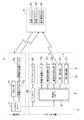
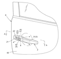
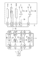
図1は、本発明の実施形態に係るシステム構成の一例を示す図である。図2は、本発明の実施形態に係る車両用ドアの一例を示す斜視図である。まず初めに図1に基づいて、スマートエントリーシステムの構成について説明する。このシステムは、リモコンと称される携帯機5を携帯する利用者(運転者)が車両に接近したこと、あるいは車室外へ移動したことを認識して、車両用ドア6の解錠と施錠とを自動的に制御する。例えば、携帯機5を携帯する利用者が車両に接近すると、車両側でこの接近を認識し、利用者が車両用ドアを開けようとしてドアハンドル2に手を掛けると、利用者の解錠の意思を認識して自動的に車両用ドア6を解錠するように制御する。
〔System configuration〕
FIG. 1 is a diagram illustrating an example of a system configuration according to an embodiment of the present invention. FIG. 2 is a perspective view showing an example of a vehicle door according to the embodiment of the present invention. First, the configuration of the smart entry system will be described with reference to FIG. This system recognizes that a user (driver) carrying a
利用者に携帯される携帯機5は、図1に示すように、車両からの電波を受信するためのアンテナやチューナなどから構成される受信システム52と、車両へ電波を送信するためのアンテナや変調回路などから構成される送信システム53と、送受信の制御や、受信信号の判断、送信信号の生成等の信号処理を行う信号処理CPU51とを有している。
As shown in FIG. 1, a
車室内には、スマートエントリーシステムの全般的な制御を行う制御手段としてのシステムECU(Electronic Control Unit)1と、携帯機5からの送信信号を受信するチューナ71と、携帯機5へ信号を送信する車室内送信アンテナ73と、車室内送信アンテナ73を介して送信する信号に対して変調、増幅等の信号処理を行う車室内ドライバ72とが、設けられている。また、システムECU1は、これら通信手段を介して携帯機5と行った通信によって、この通信機5の車両への接近又は車室外への移動を認識する認識手段を有している。
In the passenger compartment, a system ECU (Electronic Control Unit) 1 as a control means for performing overall control of the smart entry system, a
図2に示すように車両用ドア6のドアパネル部には、車両用ドア6の開閉の操作を行うための操作部として、ドアハンドル2が備えられている。このドアハンドル2は、車両用ドア6のドアパネル部の内部に備えられたハンドルフレーム8(図3参照)によって保持されている。
As shown in FIG. 2, the
図1に示すように、車両用ドア6に取り付けられたドアハンドル2には、携帯機5に信号を送信する車室外送信アンテナ74、ドアハンドル2に対する利用者の操作を検知する操作検知部3、車両用ドア6の解錠又は施錠の状態を報知する発光部4とを備えている。そして、ドアハンドル2を車両用ドア6に保持するハンドルフレーム8の内部には、ドアハンドル2に設けられた各部との信号の受け渡しを行う車室外ドライバ9が設けられている。また、車両用ドア6のドアパネル部の内部には、この車両用ドア6のロック(鍵)機構を作動させて、解錠、施錠を行うドアアクチュエータ62と、このドアアクチュエータ62を制御するドアECU61とを有している。ドアECU61と車室外ドライバ9は、システムECU1によって制御されている。
As shown in FIG. 1, the
尚、本実施形態では、ドアハンドル2に設けられた操作検知部3は、利用者の解錠の意思を検知するための解錠操作検知部31と、施錠の意思を検知するための施錠操作検知部32との二つを有している。また、ドアハンドル2から異なる方向に向けて発光するように発光部4は、第一発光部41と、第二発光部42との二つを有している。例えば、図2に示すように第一発光部41はドアハンドル2と車両用ドア6との間の空間に向かって発光し、第二発光部42はドアハンドル2の外側に向かって発光する。
In this embodiment, the
〔各部の構成〕
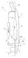
図3は、図2のA方向から見たドアハンドル部の断面図である。図3に示すように、ドアパネル60を挟んで、ハンドルフレーム8によって、ドアハンドル2が保持されている。また、ハンドルフレーム8にはハンドルキャップ21が保持されており、このハンドルキャップ21には、手動による機械的キー操作で車両用ドア6の解錠や施錠を行う場合に使用されるキーシリンダー22が設けられている。ハンドルフレーム8内には車室外ドライバ9が設けられ、ワイヤーハーネス91を介してドアハンドル2内の各部及び車室内のシステムECU1と接続されている。
[Configuration of each part]
FIG. 3 is a cross-sectional view of the door handle portion viewed from the direction A in FIG. As shown in FIG. 3, the
ドアハンドル2内部には車室外送信アンテナ74、操作検知部3、発光部4が設けられている。図3に示すように、車室外送信アンテナ74はドアハンドル2の中央部に設置されている。本実施形態では、フェライトを用いたループアンテナで構成しているが、使用する周波数帯に対応してドアハンドル2内に設置可能であればこれに限ることはない。
Inside the
ドアハンドル2のドアパネル60(車両用ドア6)に対向しない側、即ち外側には施錠操作検知部32が、ドアハンドル2のドアパネル60と対向する側、即ち裏側には解錠操作検知部31が設けられている。利用者が車両用ドア6を開けようとする場合には、ドアハンドル2を手で引く動作を行う。このとき、ドアハンドル2に掛けられた手の接触を検知するために、ドアハンドル2の裏側に解錠操作検知部31が設けられている。施錠操作検知部32は、利用者が降車し、車両用ドア6を閉めた後、ドアハンドル2の外側を指等で押したり、触れたりすることで、施錠の意思を認識するために、ドアハンドル2の外側に設けられている。
The side of the
ドアハンドル2の裏側には、解錠操作検知部31の近傍に、発光部4としてドアハンドル2とドアパネル60(車両用ドア6)との間の空間に向けて発光するように、第一発光部41が配置されている。これによって、利用者が手を入れるべき目標位置、即ち、車両用ドア6とドアハンドル2との間の空間が照明され、好適に報知することができる。
On the back side of the
ドアハンドル2の外側には、外側に向かって発光する第二発光部42が、施錠操作検知部32を囲うようにして配置されている。即ち、施錠操作検知部32を囲う第二発光部42が発光すると、これが光装飾部として機能し、ドアハンドル2の外側から良好に視認可能となって施錠操作検知部32の位置を示すことができる。また、この施錠操作検知部32を利用者が指で触った場合に、利用者の指で発光する第二発光部42の一部が隠されてしまっても周状に配置されているので外部から良好に認識できる。この配置に際しては、図2に示すように周囲一周連続していても良いし、断続的でも良い。つまり、施錠操作検知部32の位置を明確に示せるような配置であれば、図2に示す形状に限るものではない。
On the outside of the
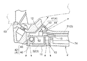
尚、図3に示すように本実施形態においては、施錠操作検知部32と第一発光部41と第二発光部42とを一体化し、スイッチモジュール10として構成している。図4は、本発明の実施形態に係る操作検知部及び発光部の構成例を示す図である。本例では、施錠操作検知部32として静電容量検出型の人検出センサを用いている。第一発光部41は、LED(発光ダイオード)43と拡散樹脂からなる拡散部材44とを有して、ドアハンドル2とドアパネル60との間の空間に向けて発光するように配置されている。第二発光部42は、LED45と拡散樹脂からなる拡散部材46とを有して、車両の外側に向けて発光するように配置されている。第二発光部42の拡散部材46は、先に述べたように施錠操作検知部32の周囲を囲うように配置されている。尚、本例ではLEDと拡散樹脂からなる拡散部材とを別々に有する例を示したが、これに限ることなく、これらが一体化されたLEDモジュールなどを用いても良い。
As shown in FIG. 3, in the present embodiment, the locking
図4に示すように第一発光部41のLED43は、基板92の一方の面に取り付けられ、第二発光部のLED45は、基板92の他方の面に取り付けられる。また、施錠操作検知部32の人検出センサも基板92に取り付けられる。基板92は、LED43用の拡散部材44が備えられたケース12に取り付けられ、LED45用の拡散部材46が備えられた蓋部11を、このケース12に被せて密閉される。このとき、施錠操作検知部32を予め蓋部11の裏面に配置しておき、施錠操作検知部32と基板92とを、ワイヤーなどで接続するように構成しておいても良い。基板92には、第一発光部41、第二発光部42、施錠操作検知部32と、車室外ドライバ9とを電気的に接続するためのケーブル13が、ケース12を介して備えられ、このケーブル13はワイヤーハーネス91に合流する。尚、このケーブル13がケース12を通る部分、及びケース12と蓋部11との境界部分はシール加工され、スイッチモジュール10は防水性を有するように密閉されて構成される。
As shown in FIG. 4, the
このようにスイッチモジュール10が防水性を有して構成されるので、施錠操作検知部32や発光部4の耐久性及び信頼性が向上する。また、一体化されているので、メンテナンスよる交換作業も容易であり、交換によって操作検知機能や発光機能や光装飾機能を低下させることもなく好ましい。
As described above, since the
尚、本実施形態では、スイッチモジュール10を構成する施錠操作検知部32として、静電容量型の人検出センサを用いて説明したがこれに限ることはなく、例えば、メカキースイッチ等を用いても良い。
In the present embodiment, the locking
〔信号処理〕
次に、上記構成における信号処理の概要を図5に基づいて説明する。図5は、本発明の実施形態に係る信号処理の一例を示すブロック図である。本実施形態においては、解錠操作検知部31及び施錠操作検知部32共に、静電容量検出型の人検出センサを用いている。車室外ドライバ9は、これら操作検知部3を構成する人検出センサのセンサドライバ93と、携帯機5へ無線信号を送信する送信用アンプ94と、発光部4を制御する第一イルミネーションドライバ95と、第二イルミネーションドライバ96とを有している。
[Signal processing]
Next, an outline of signal processing in the above configuration will be described with reference to FIG. FIG. 5 is a block diagram showing an example of signal processing according to the embodiment of the present invention. In the present embodiment, both the unlocking
システムECU1からの指令により、リクエスト信号がCLG端子を介して送信用アンプ94に伝達されると、このリクエスト信号は送信用アンプ94で変調、増幅され、ANT1端子、ANT2端子を介してドアハンドル2内の車室外送信アンテナ74から車外へ電波として送信される。
When a request signal is transmitted to the
操作検知部3からの検知信号は、STG1端子及びSTG2端子を介してセンサドライバ93へ伝達される。システムECU1が利用者の解錠の意思を認識する必要がある場合には、STG1端子より入力される解錠操作検知部31からの信号がセンサドライバ93を介してシステムECU1へ伝達されるように、システムECU1がSEL端子を介してセンサドライバ93を制御する。システムECU1が利用者の施錠の意思を認識する必要がある場合には、STG2端子より入力される施錠操作検知部32からの信号がセンサドライバ93を介してシステムECU1へ伝達されるように、システムECU1がSEL端子を介してセンサドライバ93を制御する。このように、SEL端子から入力された信号によって選択された操作検知信号がSENS端子を介して、システムECU1へ伝達される。
A detection signal from the
システムECU1は、車両用ドア6の解錠や施錠の状態に応じて発光部4を制御する。システムECU1は、ILM1端子、ILM3端子を介して、それぞれ第一イルミネーションドライバ95、第二イルミネーションドライバ96を制御し、発光部4の駆動信号を出力させて、ILM2端子、ILM4端子を介して第一発光部41、第二発光部42を発光させる。本実施形態において、第一発光部41及び第二発光部42は、LED43及びLED45を有しており、抵抗47及び抵抗48は、これらLEDに流れる電流の制限抵抗である。尚、ここで、発光部4の制御とは、点灯、消灯の制御や、連続点灯、間欠点灯(点滅)の制御などである。また、LED43やLED45が単色のLEDではなく、複数色の発光が可能な素子であった場合には、発光色を選択する制御を行っても良い。
The system ECU 1 controls the
〔解錠動作〕
続いて、上記構成において解錠、施錠を制御する動作フローについて説明する。図6は、本発明の実施形態に係る解錠動作を示すフローチャートである。
[Unlocking operation]
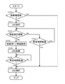
Next, an operation flow for controlling unlocking and locking in the above configuration will be described. FIG. 6 is a flowchart showing the unlocking operation according to the embodiment of the present invention.
車両が施錠されて駐車した状態において、この車両に対して登録された電子キーである携帯機5を認識するために、システムECU1は車両用ドア6のドアパネル60に設置された車室外ドライバ9にリクエスト信号を出力する。車室外ドライバ9内の送信用アンプ94は、このリクエスト信号を変調、増幅して、ドアハンドル2に設置された車室外送信アンテナ74から車外に電波を送信する。ここで携帯機5が車両に接近すると、この送信された電波が携帯機5の受信システム52で受信される。そして、携帯機5は、受信した信号を信号処理CPU51で信号処理して、受信した信号の属性や登録コードなどの返信情報を、送信システム53を介して送信する。ここで、属性とは、例えば受信した信号が車室外送信アンテナ74を介したものであること等の出所を示す情報である。車両側では、この携帯機5から送信された電波をチューナ71で受信し、システムECU1は返信情報から属性や登録コードなどを確認し、この車両に対して登録された電子キーとしての携帯機5が接近してきたことを認識する(処理S100)。
In the state where the vehicle is locked and parked, in order to recognize the
携帯機5を認識すると、スマートエントリーシステムは解錠検出モードに移行する。解錠検出モードに移行したことを利用者に報知するために、システムECU1は、第一発光部41を発光駆動する。即ち、車室外ドライバ9の第一イルミネーションドライバ95を介して第一発光部41のLED43を点灯する(処理S101)。さらに、システムECU1は、SEL端子を介して車室外ドライバ9のセンサドライバ93を制御し、解錠操作検知部31からの検知信号が入力されるか否かを所定時間に亘って観測する(処理S102及びS107)。所定時間経過しても、解錠操作検知部31からの検知信号がSENS端子を介してシステムECU1に伝達されなければ、LED43を消灯し(処理S106)、処理を終了する。
When the
所定時間内に解錠操作検知部31からの検知信号が入力されると、システムECU1はドアECU61に解錠制御を指示し、ドアアクチュエータ62が駆動されて、車両用ドア6が解錠される(処理S103)。車両用ドア6が解錠されると、システムECU1はLED43を間欠的に点灯(点滅)させて(処理S104)、車両用ドア6が解錠されたことを利用者に報知する。この点滅を所定時間行うと(処理S105)、LED43を消灯し(処理S106)、スマートエントリーシステムによる解錠処理を終了する。
When a detection signal from the unlocking
尚、この点滅パターンは利用者が認識できるパターンであれば、いかなるパターンでも良い。また、本例ではLED43の点灯と点滅とによって、車両用ドア6の状態を区別したが、LED43が発光色可変なLEDなどであった場合には、その発光色を異ならせるように制御することで区別しても良い。勿論、LED43の点灯と点滅との報知動作を逆にしても良いし、点滅や点灯と、発光色の変化とを組み合わせて報知するようにしても良い。
The blinking pattern may be any pattern as long as it can be recognized by the user. In this example, the state of the
このように、携帯機5を携帯した利用者が、車両に近づき、ドアを開けようとして、ドアハンドル2に手を掛けたことによって、良好に車両用ドア6を解錠することができ、さらに解錠検出が可能な状態(例えばLED43点灯)であるかや、解錠したこと(例えばLED43点滅)が、明確に報知できるので、利便性に優れたシステムとすることができる。また、夜間など周囲が暗い場合には、ドアハンドル2の位置が利用者に判別しにくい場合があるが、本実施形態によれば、車両用ドア6とドアハンドル2とが対向する部分の空間が照明されるので、良好にドアハンドル2に手を掛けることができる。その結果、ドアハンドル2に設けられた解錠操作検知部31によって利用者の解錠の意思が良好に検知できるので、スマートエントリーシステムも良好に働き、利用者にとっての利便性が向上する。
Thus, the user carrying the
〔施錠動作〕
図7は、本発明の実施形態に係る施錠動作を示すフローチャートである。図7に基づいて、利用者の降車時の施錠動作について説明する。利用者が車室内にいる場合には、利用者によって携帯される携帯機5(電子キー)も車室内にある。携帯機5は、車室内に設置された車室内ドライバ72で変調、増幅され、車室内に設置された車室内送信アンテナ73から送信されたリクエスト信号を受信している。携帯機5は、受信した信号を信号処理CPU51で信号処理して、受信信号の属性や登録コードなどの返信情報を、送信システム53を介して送信する。この携帯機5から送信された電波はチューナ71で受信され、システムECU1はこの返信情報を確認して、携帯機5が車室内にあることを認識している。
[Locking operation]
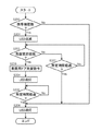
FIG. 7 is a flowchart showing a locking operation according to the embodiment of the present invention. Based on FIG. 7, the locking operation when the user gets off will be described. When the user is in the passenger compartment, the portable device 5 (electronic key) carried by the user is also in the passenger compartment. The
この状態において、利用者が携帯機5を携帯して降車し、車両用ドア6を閉めると、上記通信が途絶え、システムECU1は、携帯機5が車室内から車室外へ移動したと認識する(処理S200)。尚、これと合わせて、解錠動作で説明したように車室外送信アンテナ74より送信される信号との通信が確立できることを確認するようにしても良い。
In this state, when the user carries the
利用者の降車、及び車両用ドア6が閉じられたことを確認すると、スマートエントリーシステムは、施錠検出モードに移行する。
施錠検出モードに移行したことを利用者に報知するために、システムECU1は、第二発光部42を発光駆動する。即ち、車室外ドライバ9の第二イルミネーションドライバ96を介して第二発光部42のLED45を間欠的に点灯(点滅)する(処理S201)。尚、この点滅パターンは利用者が認識できるパターンであれば、いかなるパターンでも良い。さらに、システムECU1は、SEL端子を介して車室外ドライバ9のセンサドライバ93を制御し、施錠操作検知部32からの検知信号が入力されるか否かを所定時間に亘って観測する(処理S202及びS207)。所定時間経過しても、施錠操作検知部32からの検知信号がSENS端子を介してシステムECU1に伝達されなければ、LED45を消灯し(処理S206)、処理を終了する。
When it is confirmed that the user gets off and the
In order to notify the user that the operation has shifted to the lock detection mode, the system ECU 1 drives the second
所定時間内に施錠操作検知部32からの検知信号が入力されると、システムECU1はドアECU61に施錠制御を指示し、ドアアクチュエータ62が駆動されて、車両用ドア6が施錠される(処理S203)。車両用ドア6が施錠されると、システムECU1はLED45を点灯させて(処理S204)、車両用ドアが施錠されたことを利用者に報知する。この点灯を所定時間行うと(処理S205)、LED45を消灯し(処理S206)、スマートエントリーシステムによる施錠処理を終了する。
When a detection signal from the locking
尚、本例ではLED45の点滅と点灯とによって、車両用ドア6の状態を区別したが、LED45が発光色可変なLEDなどであった場合には、その発光色を異ならせるように制御することで区別しても良い。勿論、LED45の点灯と点滅との報知動作を逆にしても良いし、点滅や点灯と、発光色の変化とを組み合わせて報知するようにしても良い。
In this example, the state of the
このように、施錠検出が可能な状態(例えばLED45点滅)であるかや、施錠したこと(例えばLED45点灯)が、明確に報知できるので、利便性に優れたシステムとすることができる。また、夜間など周囲が暗い場合には、ドアハンドル2の外側に設けられた施錠操作検知部32の位置が利用者に判別しにくい場合があるが、本実施形態によれば、施錠操作検知部32の周囲に拡散部材46を備えた発光部42を設けているので、例えば施錠操作検知部32を指で操作する場合でも、拡散部材46が全て隠れることがなく、良好に施錠操作検知部32を操作することができる。その結果、施錠操作検知部32によって利用者の解錠の意思が良好に検知できるので、スマートエントリーシステムも良好に働き、利用者にとっての利便性が向上する。
As described above, since it is possible to clearly notify whether the lock detection is possible (for example, the
以上、本発明によって、車両用ドアの解錠・施錠の状態を人が確実に認識できるように報知を行うことが可能な車両用ドア開閉装置を提供することが可能となる。 As described above, according to the present invention, it is possible to provide a vehicle door opening / closing device capable of performing notification so that a person can surely recognize the unlocked / locked state of the vehicle door.
2 ドアハンドル
6 車両用ドア
31 解錠操作検知部
41 第一発光部
2
Claims (6)
前記車両用ドアの開閉操作を行うドアハンドルと、
利用者による前記ドアハンドルの操作状態を検知するために、前記ドアハンドルの前記車両用ドアと対向する側に設けられた解錠操作検知部と、
利用者による前記ドアハンドルの操作状態を検知するために、前記ドアハンドルの前記車両用ドアと対向しない側に設けられた施錠操作検知部と、
前記携帯機の車両への接近が認識された時に前記制御手段により駆動されて前記ドアハンドルと前記車両用ドアとの間の空間に向けて発光するように配置された第一発光部と、
前記施錠操作検知部の周囲を囲って設けられ、前記施錠操作検知部に対する利用者による能動操作時に前記利用者により前記ドアハンドルの一部が隠されても前記ドアハンドルの外部から視認可能な光装飾部を有し、前記携帯機が車室内から車室外に移動したことが認識された時に前記制御手段により駆動されて、前記車両用ドアと対向しない側である外側に向けて発光するように配置された第二発光部と、
前記施錠操作検知部と前記第一発光部と前記第二発光部とが、一体化され、密閉されて構成されて、前記ドアハンドル内に収容されるスイッチモジュールと、を備える車両用ドア開閉装置。 The communication between the portable device that is carried by the user, as well as recognize the portable device recognizes the intention of the user of the unlocking or locking for a vehicle door, unlocking of the vehicle door or A vehicle door opening and closing device provided with a control means for controlling locking,
A door handle for opening and closing the vehicle door;
In order to detect the operation state of the door handle by the user, an unlocking operation detection unit provided on the side of the door handle facing the vehicle door;
In order to detect an operation state of the door handle by a user, a locking operation detection unit provided on a side of the door handle not facing the vehicle door;
A first light emitting unit arranged to emit light toward a space between the door handle and the vehicle door when driven by the control means when the approach of the portable device to the vehicle is recognized ;
Light that is provided around the locking operation detection unit and is visible from the outside of the door handle even when a part of the door handle is hidden by the user during an active operation by the user on the locking operation detection unit It has a decoration part, and when it is recognized that the portable device has moved from the vehicle interior to the vehicle exterior, it is driven by the control means so as to emit light toward the outside that is not opposed to the vehicle door. A second light emitting unit disposed ;
The door opening and closing device for vehicles provided with the switch module by which the said lock operation detection part, said 1st light emission part, and said 2nd light emission part are integrated and sealed, and are accommodated in the said door handle. .
前記第二発光部は、前記光装飾部を構成する拡散樹脂からなる拡散部材と発光ダイオードとを有して構成され、The second light emitting unit is configured to include a diffusion member and a light emitting diode made of a diffusion resin that constitutes the light decoration unit,
前記スイッチモジュールは、The switch module is
前記第一発光部の発光ダイオードが一方の面に実装され、前記第二発光部の発光ダイオード及び前記施錠操作検知部が他方の面に実装される基板と、The light emitting diode of the first light emitting unit is mounted on one surface, the light emitting diode of the second light emitting unit and the locking operation detection unit are mounted on the other surface, and
当該基板及び前記制御手段を電気的に接続するケーブルと、A cable for electrically connecting the substrate and the control means;
前記ケーブルが通る部分がシール加工され、前記基板が収容されるケースと、A case in which a portion through which the cable passes is sealed and the substrate is accommodated;
当該基板に被せられ、前記ケースとの境界がシール加工されて前記ケースを密閉する蓋部と、を有して構成される請求項1に記載の車両用ドア開閉装置。The vehicle door opening and closing device according to claim 1, further comprising: a lid that covers the substrate and seals the case by sealing a boundary with the case.
前記利用者により携帯される携帯機との間の通信により、前記携帯機が車室内から車室外に移動したことを認識し、この状態での前記施錠操作検知部の検知情報に基づいて前記車両用ドアに対する前記利用者の施錠意思を認識するものであり、
前記車両用ドアを解錠したとき、或いは前記携帯機の接近を認識したときの何れか一方である場合には、前記第一発光部を連続的に発光駆動し、
前記車両用ドアを解錠したとき、或いは前記携帯機の接近を認識したときの何れか他方である場合には、前記第一発光部を間欠的に発光駆動し、
前記車両用ドアを施錠したとき、或いは前記携帯機の車室外への移動を認識したときの何れか一方である場合には、前記第二発光部を連続的に発光駆動し、
前記車両用ドアを施錠したとき、或いは前記携帯機の車室外への移動を認識したときの何れか他方である場合には、前記第二発光部を間欠的に発光駆動する請求項1又は2に記載の車両用ドア開閉装置。 Wherein the control means, the communication between the portable device to be carried by the user, to recognize the approach of the vehicle of the portable unit, on the basis of the detection information of the unlocking operation detecting portion in this state Recognizing the user's intention to unlock the vehicle door,
Recognizing that the portable device has moved from the vehicle interior to the vehicle interior by communication with the portable device carried by the user, and based on the detection information of the locking operation detection unit in this state, the vehicle Recognizing the user's intention to lock the door.
The door can to have unlocked the vehicle, or wherein when it is one of when it recognizes the contact near the portable device, continuously emitting driving the first light emitting portion,
The door can to have unlocked the vehicle, or wherein when an other one of when it recognizes the contact near the portable device intermittently emitting driving the first light emitting portion,
When the vehicle door is locked or when the portable device is recognized as moving outside the vehicle compartment, the second light emitting unit is continuously driven to emit light,
When locking the door the vehicle, or wherein when an other one of when it recognizes the movement of the exterior of the portable machine, according to claim 1 for intermittently emitting driving the second light emitting portion or two The vehicle door opening and closing device described in 1.
Priority Applications (4)
| Application Number | Priority Date | Filing Date | Title |
|---|---|---|---|
| JP2004186429A JP4257601B2 (en) | 2004-06-24 | 2004-06-24 | Vehicle door opening and closing device |
| EP20050013620 EP1609674A1 (en) | 2004-06-24 | 2005-06-23 | Opening/closing apparatus for vehicle door |
| CNB200510079596XA CN100476888C (en) | 2004-06-24 | 2005-06-23 | Vehicle door switch |
| US11/165,041 US7333021B2 (en) | 2004-06-24 | 2005-06-24 | Opening/closing apparatus for vehicle door |
Applications Claiming Priority (1)
| Application Number | Priority Date | Filing Date | Title |
|---|---|---|---|
| JP2004186429A JP4257601B2 (en) | 2004-06-24 | 2004-06-24 | Vehicle door opening and closing device |
Publications (2)
| Publication Number | Publication Date |
|---|---|
| JP2006009352A JP2006009352A (en) | 2006-01-12 |
| JP4257601B2 true JP4257601B2 (en) | 2009-04-22 |
Family
ID=35058851
Family Applications (1)
| Application Number | Title | Priority Date | Filing Date |
|---|---|---|---|
| JP2004186429A Expired - Fee Related JP4257601B2 (en) | 2004-06-24 | 2004-06-24 | Vehicle door opening and closing device |
Country Status (4)
| Country | Link |
|---|---|
| US (1) | US7333021B2 (en) |
| EP (1) | EP1609674A1 (en) |
| JP (1) | JP4257601B2 (en) |
| CN (1) | CN100476888C (en) |
Families Citing this family (83)
| Publication number | Priority date | Publication date | Assignee | Title |
|---|---|---|---|---|
| JP4240307B2 (en) * | 2004-06-22 | 2009-03-18 | アイシン精機株式会社 | Vehicle door opening and closing device |
| DE102004038569B3 (en) * | 2004-08-06 | 2005-10-20 | Huf Huelsbeck & Fuerst Gmbh | An automobile door handle |
| WO2006035623A1 (en) * | 2004-09-28 | 2006-04-06 | Aisin Seiki Kabushiki Kaisha | Antenna assembly and door handle unit |
| US20060209550A1 (en) * | 2005-03-18 | 2006-09-21 | Fabiao Solange B | Fixture for a door |
| JP2007138613A (en) * | 2005-11-21 | 2007-06-07 | Nissan Motor Co Ltd | Occupant approach detection device, occupant approach detection system, and occupant approach detection method |
| US8077011B2 (en) * | 2006-02-24 | 2011-12-13 | Denso International America, Inc. | Apparatus for automatically initiating sequence of vehicle functions |
| DE102006019284A1 (en) * | 2006-04-26 | 2007-10-31 | Bayerische Motoren Werke Ag | Motor vehicle, has sensor device producing and emitting sensor signal as reaction to pre-field light or door handle light, and control device arranged such that releasing mechanism is automatically activated depending on sensor signal |
| DE102006021120B9 (en) * | 2006-05-04 | 2018-09-06 | Huf Hülsbeck & Fürst Gmbh & Co. Kg | actuator |
| DE102006035223A1 (en) * | 2006-07-26 | 2008-02-07 | Huf Hülsbeck & Fürst Gmbh & Co. Kg | Locking system for vehicles |
| DE102006061518A1 (en) * | 2006-12-20 | 2008-06-26 | Huf Hülsbeck & Fürst Gmbh & Co. Kg | Actuator for closing and opening a movable part |
| ITMI20070629A1 (en) * | 2007-03-29 | 2008-09-30 | Valeo Sicurezza Abitacolo Spa | HANDLE FOR VEHICLES WITH ILLUMINATING DEVICE |
| DE102007016351A1 (en) * | 2007-04-03 | 2008-10-09 | Huf Hülsbeck & Fürst Gmbh & Co. Kg | External operation for locks on doors, flaps and the like |
| JP4540004B2 (en) * | 2007-04-16 | 2010-09-08 | 庄吾 土田 | Blinker lamps that can change color |
| WO2008137634A1 (en) | 2007-05-03 | 2008-11-13 | Donnelly Corporation | Illumination module for a vehicle |
| DE102007040294B4 (en) | 2007-08-24 | 2020-07-09 | Huf Hülsbeck & Fürst Gmbh & Co. Kg | Handle device |
| EP2062776A1 (en) * | 2007-11-20 | 2009-05-27 | Mazda Motor Corporation | Illumination device for a vehicle and method of controlling an illumination device |
| JP2009126313A (en) * | 2007-11-22 | 2009-06-11 | Aisin Seiki Co Ltd | Vehicle mall |
| DE102007059069A1 (en) * | 2007-12-07 | 2009-06-10 | Volkswagen Ag | Actuating device for use in door outside handle of motor vehicle-locking system, has sensor for detecting control action of operator, and signal transmitter arranged in or near to sensor detection regions |
| JP5292802B2 (en) * | 2007-12-21 | 2013-09-18 | スズキ株式会社 | Vehicle door |
| JP5324816B2 (en) | 2008-05-08 | 2013-10-23 | アイシン精機株式会社 | Vehicle door handle |
| US8269615B2 (en) * | 2008-05-16 | 2012-09-18 | Aisin Seiki Kabushiki Kaisha | Door handle and locking system |
| KR100974550B1 (en) * | 2008-07-15 | 2010-08-11 | 현대자동차주식회사 | Vehicle Door Lock Control System |
| US7866860B2 (en) * | 2008-07-22 | 2011-01-11 | Tyco Electronics Canada Ulc | Handle assembly with controlled light distribution |
| FR2937597B1 (en) * | 2008-10-23 | 2011-07-15 | Valeo Spa | LIGHTING MODULE FOR BELONGING TO A LEVER FOR THE GRIPPING OF A MOTOR VEHICLE OPENING |
| KR20100053864A (en) * | 2008-11-13 | 2010-05-24 | 현대자동차주식회사 | Handle structure of door outside |
| JP5270421B2 (en) * | 2009-03-30 | 2013-08-21 | 株式会社アルファ | Vehicle door handle device |
| FR2943601B1 (en) * | 2009-03-31 | 2013-01-04 | Continental Automotive France | INTEGRATED LIGHT EMITTING DETECTION DEVICE FOR MOTOR VEHICLE |
| US8007147B2 (en) * | 2009-05-06 | 2011-08-30 | Yung-Fa Lin | Vehicle door safety warning lamp |
| US10017977B2 (en) * | 2009-08-21 | 2018-07-10 | Uusi, Llc | Keyless entry assembly having capacitance sensor operative for detecting objects |
| IT1396932B1 (en) * | 2009-11-20 | 2012-12-20 | Valeo Spa | COMMAND DEVICE FOR RELEASING THE HANDLE OF A VEHICLE WITH AN EXTERNAL COMMAND ORGAN. |
| DE102010016526A1 (en) | 2010-04-19 | 2011-10-20 | Huf Hülsbeck & Fürst Gmbh & Co. Kg | Exterior door handle with passive entry assemblies and a lighting assembly |
| US10576896B2 (en) | 2010-10-01 | 2020-03-03 | Magna Mirrors Of America, Inc. | Vehicle exterior mirror system with light module |
| US8764256B2 (en) | 2010-10-01 | 2014-07-01 | Magna Mirrors Of America, Inc. | Vehicle exterior mirror system with light module |
| US8579481B2 (en) * | 2010-10-28 | 2013-11-12 | AISIN Technical Center of America, Inc. | Lit door handle for a vehicle |
| KR101230896B1 (en) * | 2010-11-23 | 2013-02-07 | 현대자동차주식회사 | Illuminator of the door outside handle for vehicle |
| DE102010061643B4 (en) * | 2010-12-30 | 2020-12-17 | Huf Hülsbeck & Fürst Gmbh & Co. Kg | External assembly component for a vehicle with a light module |
| US9399879B2 (en) * | 2011-04-29 | 2016-07-26 | Trimark Corporation | Vehicle compartment door handle assembly |
| DE102011080185A1 (en) * | 2011-08-01 | 2013-02-07 | BSH Bosch und Siemens Hausgeräte GmbH | Home appliance with antenna |
| KR101189562B1 (en) | 2012-01-03 | 2012-10-11 | 주식회사 웰리스 | Appratus for alram of door locking status using vibro speaker |
| JP5692532B2 (en) | 2012-02-21 | 2015-04-01 | アイシン精機株式会社 | Opening and closing body control device for vehicle |
| DE102012105117A1 (en) * | 2012-06-13 | 2013-12-19 | Huf Hülsbeck & Fürst Gmbh & Co. Kg | Approach detecting device |
| US9957737B2 (en) * | 2012-06-29 | 2018-05-01 | Ford Global Technologies, Llc | Flush-mounted door handle for vehicles |
| JP5974693B2 (en) * | 2012-07-10 | 2016-08-23 | アイシン精機株式会社 | Antenna drive device |
| FR2998758B1 (en) | 2012-11-26 | 2018-05-04 | Continental Automotive France | ON-BOARD LIGHTING DEVICE IN A MOTOR VEHICLE AND ASSOCIATED METHOD OF CONTROLLING A LIGHT SOURCE |
| DE102012222175A1 (en) * | 2012-12-04 | 2014-06-18 | Robert Bosch Gmbh | Method and device for opening a door of a vehicle |
| US9227558B2 (en) * | 2013-01-14 | 2016-01-05 | GM Global Technology Operations LLC | Vehicle exterior door handle lighting |
| US9670702B2 (en) | 2013-02-13 | 2017-06-06 | Honda Motor Co., Ltd. | Lock control device for vehicle |
| JP5932708B2 (en) * | 2013-04-22 | 2016-06-08 | 株式会社ホンダロック | Outdoor handle device for vehicle door |
| DE202013005022U1 (en) * | 2013-05-31 | 2014-09-02 | Kiekert Aktiengesellschaft | Motor vehicle door |
| JP6064806B2 (en) * | 2013-06-21 | 2017-01-25 | アイシン精機株式会社 | Vehicle door handle |
| TWI464318B (en) * | 2013-07-29 | 2014-12-11 | Univ Nat Taipei Technology | Sensing device installed in a handle and vehicle door handle |
| JP6195505B2 (en) * | 2013-11-19 | 2017-09-13 | 株式会社小糸製作所 | Door handle |
| JP5955303B2 (en) | 2013-11-19 | 2016-07-20 | 株式会社小糸製作所 | Door handle |
| FR3015004A1 (en) * | 2013-12-18 | 2015-06-19 | Filec | ELECTRONIC DEVICE HOUSING TO BE PLACED INTO A MOTOR VEHICLE DOOR HANDLE, CORRESPONDING ELECTRONIC DEVICE AND CORRESPONDING DOOR HANDLE |
| JP6405639B2 (en) * | 2014-02-06 | 2018-10-17 | アイシン精機株式会社 | Control device and vehicle control system |
| US9666005B2 (en) | 2014-02-14 | 2017-05-30 | Infinitekey, Inc. | System and method for communicating with a vehicle |
| US9624693B2 (en) * | 2015-03-03 | 2017-04-18 | The Boeing Company | Integrated locks with visual indicators for aircraft galley systems |
| JP6660673B2 (en) * | 2015-04-10 | 2020-03-11 | 株式会社アルファ | Vehicle steering device |
| JP2016216963A (en) * | 2015-05-18 | 2016-12-22 | 株式会社東海理化電機製作所 | Locking/unlocking guide illumination system |
| JP6480284B2 (en) * | 2015-07-31 | 2019-03-06 | 株式会社沖データ | Image forming apparatus and image forming method |
| WO2017180454A1 (en) * | 2016-04-11 | 2017-10-19 | Carrier Corporation | Capturing communication user intent when interacting with multiple access controls |
| KR102098137B1 (en) | 2016-04-15 | 2020-04-08 | 가부시키가이샤 덴소 | System and method for setting real-time location |
| JP6765070B2 (en) * | 2016-06-01 | 2020-10-07 | パナソニックIpマネジメント株式会社 | Electric lock system and electric lock device |
| DE102016212527B4 (en) | 2016-07-08 | 2019-08-08 | Magna Mirrors Holding Gmbh | Blink unit for an exterior mirror |
| US11671807B2 (en) | 2016-11-11 | 2023-06-06 | Carnival Corporation | Wireless device and methods for making and using the same |
| US12058596B2 (en) | 2016-11-11 | 2024-08-06 | Carnival Corporation | Signal processing of a wireless guest engagement system and methods for making and using the same |
| US12342255B2 (en) | 2016-11-11 | 2025-06-24 | Carnival Corporation | Antenna device for a wireless guest engagement system and methods for making and using the same |
| US10045184B2 (en) * | 2016-11-11 | 2018-08-07 | Carnival Corporation | Wireless guest engagement system |
| WO2018112224A1 (en) | 2016-12-14 | 2018-06-21 | Denso International America, Inc. | Method and system for establishing microlocation zones |
| WO2018168033A1 (en) * | 2017-03-16 | 2018-09-20 | テイ・エス テック株式会社 | Illuminating device |
| CN111615578B (en) * | 2018-01-17 | 2022-07-29 | 阿尔卑斯阿尔派株式会社 | door handle |
| JP6674484B2 (en) * | 2018-01-18 | 2020-04-01 | 矢崎総業株式会社 | Lighting device for assist grip |
| US11270536B2 (en) | 2018-06-21 | 2022-03-08 | Assa Abloy Ab | Method for remotely unlocking a lock |
| US10604067B2 (en) | 2018-08-29 | 2020-03-31 | Hyundai Motor Company | System and method for controlling vehicle seating arrangement |
| CN111476618B (en) * | 2019-01-07 | 2023-11-07 | 北京骑胜科技有限公司 | Method for managing shared vehicles, vehicle and computer readable medium |
| JP7221738B2 (en) * | 2019-03-05 | 2023-02-14 | 株式会社アイシン | Vehicle operation detection device |
| DE102019004209B4 (en) * | 2019-06-13 | 2025-07-10 | Mercedes-Benz Group AG | Illumination of a vehicle door gap to support the operability of automatic door opening systems |
| JP7270750B2 (en) * | 2019-09-18 | 2023-05-10 | アルプスアルパイン株式会社 | Storage case and vehicle borrowing system |
| GB2594441A (en) * | 2020-01-29 | 2021-11-03 | Arrival Ltd | Lamp assembly for a vehicle |
| CN113063580B (en) * | 2021-03-31 | 2023-07-11 | 东风商用车有限公司 | Endurance test bench and endurance test method for door lock system |
| CN113432068B (en) * | 2021-07-30 | 2022-11-25 | 岚图汽车科技有限公司 | Vehicle door outward opening handle LED lamp and structure assembly thereof |
| US12567001B2 (en) | 2022-02-03 | 2026-03-03 | Denso Corporation | Machine learning generation for real-time location |
| FR3167403A1 (en) * | 2024-10-10 | 2026-04-17 | Renault Sas | Vehicle door opening control device incorporating a light system. |
Family Cites Families (17)
| Publication number | Priority date | Publication date | Assignee | Title |
|---|---|---|---|---|
| JP2760089B2 (en) * | 1989-10-09 | 1998-05-28 | 日産自動車株式会社 | Door handle device |
| US6070998A (en) * | 1998-01-23 | 2000-06-06 | General Motors Corporation | Fiber optic lighting system for vehicle door handle |
| DE19822733C2 (en) | 1998-05-20 | 2001-05-10 | Bayerische Motoren Werke Ag | Device for illuminating the apron on the side of a vehicle |
| JP2000045593A (en) | 1998-07-24 | 2000-02-15 | Toyota Motor Corp | Vehicle equipment operation receiver |
| JP3840862B2 (en) * | 1999-12-24 | 2006-11-01 | 豊田合成株式会社 | Inside handle lighting device |
| JP2001336321A (en) * | 2000-05-31 | 2001-12-07 | Omron Corp | Control device |
| GB0016089D0 (en) * | 2000-07-01 | 2000-08-23 | Honeywell Control Syst | Keyless access sensor system |
| DE10121046A1 (en) * | 2001-04-28 | 2002-11-07 | Huf Huelsbeck & Fuerst Gmbh | External actuation for vehicle locks on doors, flaps or the like. |
| US6848818B2 (en) * | 2001-10-24 | 2005-02-01 | Donnelly Corporation | Vehicle handle assembly with cup lighting |
| JP3901034B2 (en) * | 2002-06-24 | 2007-04-04 | アイシン精機株式会社 | Vehicle door opening and closing device |
| JP4142378B2 (en) * | 2002-09-19 | 2008-09-03 | 株式会社アルファ | Vehicle door locking / unlocking control system |
| JP2004175252A (en) * | 2002-11-28 | 2004-06-24 | Tokai Rika Co Ltd | Lighting control device for vehicle |
| JP2004257126A (en) * | 2003-02-26 | 2004-09-16 | Aisin Seiki Co Ltd | Vehicle door opening and closing device |
| US7057124B2 (en) * | 2003-04-22 | 2006-06-06 | Aisin Seiki Kabushiki Kaisha | Push switch apparatus |
| TWM246202U (en) * | 2003-05-20 | 2004-10-11 | Exon Science Inc | Vehicular door handle module |
| KR20050024648A (en) * | 2003-09-01 | 2005-03-11 | 현대자동차주식회사 | Emitting Apparatus Indicating Location of Door Outside Handle |
| JP4240307B2 (en) | 2004-06-22 | 2009-03-18 | アイシン精機株式会社 | Vehicle door opening and closing device |
-
2004
- 2004-06-24 JP JP2004186429A patent/JP4257601B2/en not_active Expired - Fee Related
-
2005
- 2005-06-23 CN CNB200510079596XA patent/CN100476888C/en not_active Expired - Fee Related
- 2005-06-23 EP EP20050013620 patent/EP1609674A1/en not_active Withdrawn
- 2005-06-24 US US11/165,041 patent/US7333021B2/en not_active Expired - Fee Related
Also Published As
| Publication number | Publication date |
|---|---|
| US7333021B2 (en) | 2008-02-19 |
| JP2006009352A (en) | 2006-01-12 |
| US20050285717A1 (en) | 2005-12-29 |
| CN100476888C (en) | 2009-04-08 |
| EP1609674A1 (en) | 2005-12-28 |
| CN1713239A (en) | 2005-12-28 |
Similar Documents
| Publication | Publication Date | Title |
|---|---|---|
| JP4257601B2 (en) | Vehicle door opening and closing device | |
| JP4240307B2 (en) | Vehicle door opening and closing device | |
| JP3901034B2 (en) | Vehicle door opening and closing device | |
| JP2004257126A (en) | Vehicle door opening and closing device | |
| JP4576837B2 (en) | Opening and closing body actuator for vehicle | |
| US10246009B2 (en) | User notification of powered system activation during non-contact human activation | |
| CN104583027B (en) | Control method for vehicle closure element and control system | |
| CN100522696C (en) | On-board illumination controlling system and method | |
| US8730021B2 (en) | Lit door handle for a vehicle | |
| US11313159B2 (en) | Gesture access system for a motor vehicle | |
| US20170050616A1 (en) | Vehicular keyless entry system | |
| JP2004175252A (en) | Lighting control device for vehicle | |
| EP3968290B1 (en) | Gesture access system for a motor vehicle | |
| US12122324B2 (en) | Vehicular power door sensing and operating system | |
| JP3159984U (en) | Pushbutton cover kit for retrofitting automobile door handles | |
| JP2004175253A (en) | Operating device for vehicle drive system and vehicle drive control system | |
| JP4498112B2 (en) | Vehicle switch | |
| JP4091406B2 (en) | Vehicle key storage device | |
| JP2006090032A (en) | Switch device and switch module for automatic door opening device | |
| JP2006083648A (en) | Locking device for motor vehicle | |
| JP2006090033A (en) | Automatic door opening device | |
| JP2005161904A (en) | Direction indicator | |
| JP2006138104A (en) | Switch for vehicle | |
| JP2005155233A (en) | Wireless unlocking device |
Legal Events
| Date | Code | Title | Description |
|---|---|---|---|
| A621 | Written request for application examination |
Free format text: JAPANESE INTERMEDIATE CODE: A621 Effective date: 20060526 |
|
| A977 | Report on retrieval |
Free format text: JAPANESE INTERMEDIATE CODE: A971007 Effective date: 20080502 |
|
| A131 | Notification of reasons for refusal |
Free format text: JAPANESE INTERMEDIATE CODE: A131 Effective date: 20080522 |
|
| A521 | Request for written amendment filed |
Free format text: JAPANESE INTERMEDIATE CODE: A523 Effective date: 20080722 |
|
| TRDD | Decision of grant or rejection written | ||
| A01 | Written decision to grant a patent or to grant a registration (utility model) |
Free format text: JAPANESE INTERMEDIATE CODE: A01 Effective date: 20090108 |
|
| A01 | Written decision to grant a patent or to grant a registration (utility model) |
Free format text: JAPANESE INTERMEDIATE CODE: A01 |
|
| A61 | First payment of annual fees (during grant procedure) |
Free format text: JAPANESE INTERMEDIATE CODE: A61 Effective date: 20090121 |
|
| R151 | Written notification of patent or utility model registration |
Ref document number: 4257601 Country of ref document: JP Free format text: JAPANESE INTERMEDIATE CODE: R151 |
|
| FPAY | Renewal fee payment (event date is renewal date of database) |
Free format text: PAYMENT UNTIL: 20120213 Year of fee payment: 3 |
|
| FPAY | Renewal fee payment (event date is renewal date of database) |
Free format text: PAYMENT UNTIL: 20130213 Year of fee payment: 4 |
|
| FPAY | Renewal fee payment (event date is renewal date of database) |
Free format text: PAYMENT UNTIL: 20140213 Year of fee payment: 5 |
|
| LAPS | Cancellation because of no payment of annual fees |