JP4256995B2 - Collating device - Google Patents
Collating device Download PDFInfo
- Publication number
- JP4256995B2 JP4256995B2 JP28598499A JP28598499A JP4256995B2 JP 4256995 B2 JP4256995 B2 JP 4256995B2 JP 28598499 A JP28598499 A JP 28598499A JP 28598499 A JP28598499 A JP 28598499A JP 4256995 B2 JP4256995 B2 JP 4256995B2
- Authority
- JP
- Japan
- Prior art keywords
- discharge
- paper
- unit
- collated
- collation
- Prior art date
- Legal status (The legal status is an assumption and is not a legal conclusion. Google has not performed a legal analysis and makes no representation as to the accuracy of the status listed.)
- Expired - Fee Related
Links
Images


Landscapes
- Controlling Sheets Or Webs (AREA)
- Collation Of Sheets And Webs (AREA)
Description
【0001】
【発明の属する技術分野】
本発明は、複数種類(内容)の用紙を1種類ずつ所定の順番で重ねて1丁合物として排出する丁合装置に関する。
【0002】
【従来の技術】
従来、複数種類の印刷物等の用紙を所定の順番で重ねて一束の丁合物を多数生成する装置として丁合装置がある。図9は従来の丁合装置の概略構成図である。
【0003】
図9に示すように、従来の丁合装置は、その上下方向に配列された複数の給紙台3a〜3jを有し、この各給紙台3a〜3jに多数積載された用紙1を所定タイミングで1枚ずつ給紙する給紙部Aと、これら給紙された複数の用紙1を上下方向に搬送しつつ丁合して丁合物とする丁合搬送部Bと、この丁合搬送部Bで搬送された丁合物をスタッカー部Dに排出する排出部Cと、この排出部Cから排出された丁合物を積載するスタッカー部Dとを備えている。
【0004】
そして、上記構成の従来の丁合装置では、給紙台3a〜3j上に種類(内容)毎に積載された多数の用紙1を丁合物とする場合、先ず、給紙台3a〜3j上の各用紙1が、給紙部Aによって上段から所定間隔の遅れをもって順次丁合搬送部Bに給紙される。給紙された各種の用紙1は、丁合搬送部Bにおいて搬送されつつ重ねられて丁合され、排出部Cを介してスタッカー部Dの排紙台42上に丁合物として排出される。
【0005】
特に、このスタッカー部Dには、排出された丁合物が積載される排紙台42が設けられているとともに、この排紙台42の上面から所定の高さ位置に満載センサ79が設けられている。この満載センサ79は、排紙台42に丁合物が排出されたことを検出するとともに、排紙台42上に丁合物が積載され所定の高さに達したことを検出することにより満載か否かを判定するものである。
【0006】
また、上記従来の丁合装置では、給紙部Aによる給紙から排出部Cによる排出を1サイクルとし、上記動作を繰り返すことによって丁合物を多数生成する。そして、従来の丁合装置では、満載センサ79で丁合物の排出を監視するとともに、排紙台42上における積載量を監視しており、丁合物が排出されたことを確認した後に、丁合物73が満載されていないかどうかを確認し、その後次サイクルを開始している。
【0007】
【発明が解決しようとする課題】
しかしながら、前記従来の丁合装置においては、上述したように、排出部74における丁合物の排出監視と、排紙台76における満載監視を一つの満載センサ79で行っていたため、次サイクルの開始が遅れるという問題があった。
【0008】
即ち、従来の丁合装置では、排紙台42上面から所定の高さ位置において、排出される丁合物の通過を確認するとともに、その後に満載を検知しなければならない。ところが、丁合物の満載を正確に判断するためには、排出された丁合物が安定するのを待たなければならず、この丁合物が安定するまでには所定の時間を要する。従って、従来の丁合装置では、各丁合サイクルにおいて逐次丁合物の安定を待たなければならず、これにより丁合動作の高速化が制限されるという問題があった。
【0009】
そこで、本発明は、前記した課題を解決すべくなされたものであり、排出部における丁合物の紙詰まり等のジャムを効果的に検出するとともに、丁合動作のサイクルを用紙のサイズに応じて調節し、また満載検出に要する時間を省略することによって動作の効率化を図ることのできる丁合装置を提供することを課題とする。
【0010】
上記課題を解決するために、請求項1に係る発明は、複数の給紙台を有し、これらの各給紙台に多数積載された用紙を所定タイミングで1枚ずつ給紙する給紙部と、この給紙部から給紙された複数の用紙を搬送しつつ丁合して丁合物とする丁合搬送部と、この丁合搬送部から搬送された丁合物を排紙台に排出する排出部と、前記排出部に設けられ、前記丁合物の有無を検出することにより該丁合物の排出を検知する排出センサと、前記排出部から排出される丁合物に干渉しない待機位置と、該排出部から排出される丁合物に干渉する干渉位置との間で変位するように回動されて、該排出部から排出される丁合物の落下位置を規制する一対の排紙ウィングとを備え、前記排出センサによって前記排出部における紙詰まりを監視し、前記給紙部による給紙から前記排出部による排出までを1サイクルとし、前記排出センサによる前記丁合物排出の検知を、次サイクル開始の契機とするとともに、該丁合物排出の検知から一定時間経過後に、前記排紙ウイングを駆動させることを特徴とする丁合装置である。
【0011】
この請求項1に係る発明によれば、排出部における紙詰まり等のジャムを監視することによって、丁合動作の最終動作である排出の段階において丁合物が詰まる等した場合には以後の丁合動作を中止するなどの対応を執ることができ、ジャムによる障害を最小限に留めることができる。また、丁合物部の排出検知を次サイクル開始の契機とすることによって、例えば、用紙の長さが短い場合は次サイクルを早期に開始することができるなど、用紙のサイズに応じてサイクル長を可変とすることができ、丁合動作を効率的に行うことができる。
【0012】
請求項2に係る発明は、請求項1に記載の丁合装置であって、前記排紙台には、排紙台に排出された丁合物の積載量を検出する満載センサを設け、この満載センサは、ONの状態が連続して所定時間以上となったときに満載と判定し、その判定は、次丁合開始のタイミングとするものである。
【0013】
この請求項2に係る発明によれば、排出部における丁合物の排出の監視と、排紙台における満載の監視を別個独立に行うため、満載の監視に要する処理時間分、サイクルを短縮することができ、丁合動作の高速化を図ることができる。
【0014】
請求項3に係る発明は、請求項2に記載の丁合装置であって、前記満載センサは、前記待機位置にある排紙ウィングの最下端と同一高さに設置されているものである。
【0016】
【発明の実施の形態】
以下、本発明の実施形態について図面を参照しつつ詳細に説明する。
【0017】
(丁合装置の全体構成)
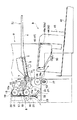
図1は、本実施形態に係る丁合装置の全体斜視図であり、図2は、丁合装置の下部における内部構造を示す側面図である。図1に示すように、丁合装置は、丁合する複数種類の用紙1を所定のタイミングで各種類1枚ずつ給紙する給紙部Aと、この給紙された複数の用紙1を垂直方向に搬送しつつ丁合し丁合物とする丁合搬送部Bと、この丁合搬送部Bからの丁合物2をスタッカー部Dに排出する排出部Cと、この排出部Cから排出される丁合物2を積載するスタッカー部Dとを備えている。また、これら各部A〜Dの操作は操作パネル部Eによって行う。
【0018】
前記給紙部Aは、その上下方向に配列された10台の給紙台3a〜3jを有し、この各給紙台3a〜3jは、図2に示すように、丁合する各主要紙を載置する固定給紙台部4と、支軸5を支点として搬送先端側が上下動する可動給紙台部6とを備えている。この可動給紙台部6にはレバー7付きの紙有無検出センサS1が設けられ、この紙有無検出センサS1によって各給紙台3a〜3jに用紙1が積載されているか否かを検出する。また、可動給紙台部6の搬送先端側の上方位置には、回転軸8に支持された給紙ローラ9が配置されている。この給紙ローラ9には、可動給紙台部6が上方に位置する場合に、これに積載された最上位置の用紙1が圧接される。
【0019】
給紙ローラ9の後方には、搬送される用紙が複数枚重なっていることを検出する重送検出センサS2が設けられている。この重送検出センサS2は、上,下ガイドプレート10,11の搬送経路を挾んで配置された発光部12と受光部13とを有し、受光部13が受光する光量によって搬送される用紙1が1枚であるか否かを検出するものである。なお、この重送検出センサS2は、本実施形態では、給紙ローラ9の回転開始時から所定時間以内にセンサ出力が有るか否かによって空送や紙づまりの有無をも検出する。
【0020】
また、各給紙台3a〜3jに対応する給紙ローラ9は、電磁クラッチ82a〜82jによって回転タイミングが制御されるものである。この電磁クラッチ82a〜82jは、図3に示す制御部68によって制御される。すなわち、同図に示すように、制御部68には、紙有無検出センサS1、重送検出センサS2及び排出センサS3の検出結果が入力され、これらの入力信号に基づき、所定のプログラムによって電磁クラッチ82a〜82jを制御する。なお、この制御部68は、電磁クラッチ82a〜82jの他、各部に駆動力を供給するメインモータや電磁ソレノイド81、排紙ウイング47,48の駆動を制御する。
【0021】
このように制御部68によって電磁クラッチ82a〜82jを駆動させることにより、上段から下段の各回転ローラ9を所定の間隔をもって回転を開始させ、各給紙台3a〜3jから、それぞれ所定のタイミングで用紙1を、順次丁合搬送部Bに給紙する。
【0022】
また、給紙ローラ9が回転されると、各給紙台上に積載された最上位置の用紙1のみが搬送される。給紙ローラ9よりも搬送下流の位置には、搬送される用紙1をガイドする上ガイドプレート10と、下ガイドプレート11とが設けられており、搬送された用紙1はこの上,下ガイドプレート10,11にガイドされて丁合搬送部Bに供給される。
【0023】
前記丁合搬送部Bは、図2に示すように、各給紙台3a〜3jに対応する上,下ガイドプレート10,11の排出側にそれぞれ設けられた搬送ローラ15と、この各搬送ローラ15に対向してそれぞれ設けられた押さえローラ16とを有する。この上下方向に配列された各押さえローラ16は図示しないバネで搬送ローラ15側に付勢されていると共に、これら押さえローラ16,16,…間には搬送ベルト17が掛けられており、各押さえローラ16は搬送ベルト17を介してそれぞれ搬送ローラ15に圧接されている。
【0024】
また、各搬送ローラ15と各押さえローラ16とに圧接状態である搬送ベルト17部分の両側には垂直ガイドプレート18,19がそれぞれ設けられ、この両側の垂直ガイドプレート18,19間に垂直搬送路20が構成されている。一方の垂直ガイドプレート18は1枚のプレートより構成されているが、他方の垂直ガイドプレート19は、給紙部Aの上,下ガイドプレート10,11と一体に複数プレートより構成されている。
【0025】
そして、各搬送ローラ15が回転すると、搬送ローラ15の摩擦力を受けて押さえローラ16によって回転自在な搬送ベルト17が移動され、給紙部Aから搬送された用紙1は、この回転する搬送ローラ15と移動している搬送ベルト17との間に挾み込まれて垂直搬送路20を下方に搬送される。ここで、上方より搬送される用紙1が下方の搬送ローラ15を通過するタイミングで下方の給紙台側の用紙1が丁合搬送部Bに搬送されることによって、下方の用紙1が上方の用紙1に重なって下方に搬送される。このような用紙1の搬送と用紙1の重ね合わせ動作が繰り返されて所望の丁合物が作成され、この丁合物が更に下方の排出部Cに搬送される。
【0026】
前記排出部Cは、図2に示すように、搬送路変更ガイドプレート21を有し、この搬送路変更ガイドプレート21は、図2にて実線で示すスタッカー用位置と、図2にて仮想線で示す後処理機用位置との間で回動自在に設けられている。搬送路変更ガイドプレート21は、本実施形態では、スタッカー用位置側に図示しないバネによって付勢されており、電磁ソレノイド81によって駆動される。
【0027】
即ち、電磁ソレノイド81がオフ状態ではスタッカー用位置に、電磁ソレノイド81がオン状態では後処理機用位置に位置される。スタッカー用位置では搬送路変更ガイドプレート21の上端が丁合搬送部Bの一方の垂直ガイドプレート18に沿うように位置され、丁合搬送部Bから搬送されてくる丁合物2はスタッカー部D側に導かれる。後処理機用位置では搬送路変更ガイドプレート21の上端が丁合搬送部Bの他方の垂直ガイドプレート19に沿うよう位置され、丁合搬送部Bから搬送されてくる丁合物はスタッカー部D側とは反対側に導かれる。
【0028】
また、搬送路変更ガイドプレート21の下方位置にはスタッカー部側ガイドプレート22と後処理機側ガイドプレート23が設けられ、この各ガイドプレート22,23上を通って丁合物2が選択的に搬送される。
【0029】
排出センサS3は、排出ローラ26,27の近傍且つ排出経路の上流において、スタッカー部側ガイドプレート22を挾んで配置された発光部24と受光部25とを有し、受光部25が受光する光量のレベルによって、丁合物2の排出タイミングを検出する。つまり、丁合物2の通過が開始すると、発光部24からの光が遮断されて受光部25の出力がHレベルとなり、通過終了で再び発光部24からの光が遮断されなくなり受光部25の出力がLレベルに戻ることから、丁合物2の排出タイミングを検出することができる。また、排出センサS3は、例えばセンサ出力のLレベルが所定時間以上連続することにより排出部Cでの紙づまりを検出する。
【0030】
スタッカー部D側ガイドプレート22の最下流で、且つ、スタッカー部Dを臨む位置には上下方向に配置された一対の排出ローラ26,27が設けられている。一対の排出ローラ26,27は略圧接状態で配置され、下方の排出ローラ27の上端部が若干スタッカー部側ガイドプレート22より上方に突出している。
【0031】
そして、上方の排出ローラ26が回転すると、これに追従して下方の排出ローラ27が回転されるもので、丁合搬送部Bから搬送されてくる丁合物は一対の排出ローラ26,27間に挿入され、この一対の排出ローラ26,27の回転によってスタッカー部Dに排出される。
【0032】
前記スタッカー部Dは、排出部Cから排出される丁合物の落下位置に設けられた排紙台42と、この排紙台42上に排出される丁合物の両外側に位置し、丁合物の排出方向を、これと直交する方向に規制する一対のサイドフェンス43,44とを有する。この一対のサイドフェンス43,44は、移動自在に設けられ、これらのサイドフェンス43,44間隔を丁合する用紙2の幅に応じて可変できる。また、排紙台42上には丁合物2の排出方向の前方を規制するフロントフェンス45が配置されている。
【0033】
また、サイドフェンス43,44の各切欠孔43a,44a内には、一対の排紙ウイング47,48が設けられている。排紙ウイング47,48は、排出部Cから排出される丁合物に干渉しない待機位置と、排出部Cから排出される丁合物2に干渉する干渉位置との間で変位するように回動されて、排出部Cから排出される丁合物の落下位置を規制するものである。本実施形態に係る丁合装置では、この排紙ウィング47,48で丁合物の落下位置を規制することにより、排紙台42における丁合物の積載形態を変化させることができる。
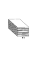
【0034】
例えば、排紙ウイング47,48を駆動せずに丁合物を積載した場合には、図4に示すようないわゆる棒積みとなり、図5(a)及び(b)に示すように、排紙ウイング47,48を交互に待機位置(図中点線で図示)及び干渉位置(図中実線で図示)間で変位させることにより、丁合物の落下位置をdだけずらして右寄せまたは左寄せに排出するようにした場合には、図5(c)に示すようないわゆる区分積みとなる。
【0035】
さらに、前記スタッカー部Dには、満載センサ50が設けられている。満載センサ50は、排紙台42上の丁合物の積載量を検出するものであり、排紙台42の上面から所定の高さ位置に配置されている。また、この満載センサ50は、丁合物の排出経路を挟んで対向配置された発光部と受光部とから構成され、受光部が受光する光量のレベルによって、丁合物2の満載を検出するものである。つまり、丁合物2が積載されて所定の高さになると、発光部からの光が遮られて受光部が受光する光量が低下し、丁合物の満載を検知することができる。
【0036】
さらに、本実施形態に係る満載センサ50は、後述する丁合シーケンスと関係なく独立して検出を行うものであるとともに、図6に示すように、受光部が受光している間はOFFの状態となり、遮光によってONの状態となり、ONの状態が連続して1000ms以上となったときに満載と判定する。従って、同図に示すように満載センサ50がONの状態となっても、その状態が連続して1000ms以下(図中の例では300ms、250ms)の場合には、満載と判定しない。
【0037】
(丁合動作)
次に、上記構成の丁合装置の丁合動作について説明する。先ず、排紙モードとして区分積みモードが選択された場合の丁合動作を説明する。
【0038】
丁合動作が開始されると、メインモータが駆動し、最上段の給紙台3aから順に最下段の給紙台3jまでの各種類(内容)の用紙1が1枚ずつ順次丁合搬送部Bに給紙される。この給紙された各用紙1は丁合搬送部Bで丁合されながら下方に搬送されつつ丁合処理がなされて丁合物2とされる。この丁合物2が排出部Cに入り、一対の排出ローラ26,27の回転によりスタッカー部Dに排出される。
【0039】
丁合物2が排出部Cを通過するに際し、排出センサS3の検出出力がLレベルからHレベルに変化したタイミングを検出すると、その所定時間経過後にスタッカ動作が開始され、排紙ウイング47が駆動し、丁合物の落下位置を規制する。
【0040】
続いて次サイクルが開始されると、上記と同様にして給紙部Aの各給紙台3a〜3jからの各用紙1が給紙され、丁合搬送部Bから丁合物2が排出部Cを介して排出される。そして、図7に示すように、排出センサS3の検出出力がLレベルからHレベルに変化したタイミングを検出すると、その所定時間(t1)経過後に、スタッカ動作が開始され、排紙ウイング48が駆動し、丁合物の落下位置を前サイクルのときとずれるように規制する。
【0041】
つまり、排出センサS3の検出出力がLレベルからHレベルに変化したタイミングを検出する毎に、左右の一対の排紙ウイング47,48を交互に干渉位置に位置させることによって、1丁合物2毎に左右にシフト量d1だけオフセットして積載される。
【0042】
次に、排紙モードとして棒積みモードが選択された場合の丁合動作を説明する。
【0043】
そして、丁合動作が開始されると、メインモータが駆動し、最上段の給紙台3aから順に最下段の1つ上の給紙台3jまでの各種類(内容)の用紙1が1枚ずつ順次丁合搬送部Bに給紙される。
【0044】
この給紙された各用紙1は丁合搬送部Bの搬送ローラ15の箇所で丁合されながら下方に搬送されつつ丁合処理がなされて所望の丁合物2とされる。この丁合物2が排出部Cに入り、一対の排出ローラ26,27の回転によりスタッカー部Dに排出される。
【0045】
ここで、丁合物2が排出部Cを通過するに際し、排出センサS3がこれを検出するが、上述した区分積みモードと相違し、排紙ウイング47,48が駆動されない。従って、排出部Cから排出された丁合物2は一対の排紙ウイング47,48に干渉されることなく落下して排紙台42上に積載される。
【0046】
(丁合シーケンス)
次に、上述したような丁合動作における各部の丁合シーケンスについて説明する。本実施形態では、上述した一連の1丁合動作を1サイクルとし、複数サイクル行う場合には、排出センサS3による丁合物排出の検知が、次サイクル開始の契機とされる。図7は、1サイクルにおける各部の動作シーケンスを示すタイミングチャートである。
【0047】
先ず、丁合サイクルが開始されると(図中▲1▼)、最上段の給紙台3aにおいて電磁クラッチ82aが駆動し給紙が開始される。このとき給紙台3aに設けられた重送検出センサS2(重送検出センサS2a)による検出が開始され、給紙台3aにおける空送を監視する。即ち、丁合サイクルが開始されてから所定時間内に「紙有り」の状態にならない場合は、空送発生と判定する。また、この重送検出センサS2は、用紙サイズ(例えば、B5横、A4、A3、A3SR等)に応じて、空送検知と同時に紙詰まり発生も監視する(図中▲6▼)。即ち、試し丁合で検出した用紙後端位置(「紙なし」)が所定の時間内に検出されない場合には、紙詰まり発生と判定する。さらに、重送検出センサS2は、給紙が開始されてから所定時間、重送発生についても監視する(図中▲5▼)。
【0048】
同一の動作を上段の給紙台3aから順に、給紙台3jまで行う。即ち、丁合サイクル開始から所定時間(図中▲2▼)後に、所定時間(図中▲3▼)だけ各給紙台の給紙クラッチを動作させ、所定のタイミングずつずらして各用紙を搬送丁合部に供給する。なお、本実施形態においては、最下段の給紙台3jの重送検出センサS2jは、最下段の給紙クラッチの動作が開始されてから、所定時間(図中▲4▼)経過後に動作を開始させる。
【0049】
全ての給紙台における給紙が完了した後、排出センサS3による排出検出を開始する。具体的には丁合サイクルが開始されてから所定時間(図中▲7▼)経過後に排出検出を開始し、所定時間内に「紙有り」にならない場合には、排出部Cにおいて紙詰まり発生と判断する。なお、排出センサS3が「紙有り」と判断してから所定時間(図中▲8▼)経過後にスタッカ動作を開始する。また、排出センサS3が「紙有り」と判断してから所定時間(図中▲9▼)経過後に「紙なし」が検出されない場合は、紙詰まり発生と判断する。
【0050】
そして、排出センサS3が「紙なし」を検出した時点で、他の▲4▼〜▲6▼、▲7▼及び▲9▼においてエラーが発生していないことを条件とし、1丁合成立となり次サイク
【外1】

【0051】
【外2】
【0052】
(丁合装置による効果)
このような本実施形態に係る丁合装置によれば、丁合物部の排出検出を次サイクル開始の契機とすることによって、例えば、用紙の長さが短い場合は次サイクルを早期に開始することができるなど、用紙のサイズに応じてサイクル長を可変とすることができ、丁合動作を効率的に行うことができる。
【0053】
また、本実施形態に係る丁合装置では、排出センサS3による検出と、満載センサ50による検出を別個独立して行い、さらに満載センサ50による満載検出を丁合シーケンスから分離しているため、満載の判定に要する時間を省略することができ、丁合動作の高速化を実現することができる。
【0054】
また、本実施形態では、排出センサS3を排出ローラ26,27の近傍であって、且つ排出経路の上流に設けているため、丁合物が排出ローラ26,27間に挿入された時点で排出完了を判定することができ、迅速に次丁合サイクルに移行することができる。
【0055】
【発明の効果】
以上説明したように、本発明の丁合装置によれば、排出部における丁合物の紙詰まり等のジャムを効果的に検出するとともに、丁合動作のサイクルを用紙のサイズに応じて調節し、満載検出に要する時間を省略することによって動作の効率化を図ることができる。
【図面の簡単な説明】
【図1】本発明の実施形態に係る丁合装置の全体斜視図である。
【図2】本発明の実施形態に係る丁合装置の給紙部と排出部及びスタッカー部の構成図である。
【図3】本発明の実施形態における、丁合装置の制御系の回路ブロック図である。
【図4】本実施形態における丁合物の積載形態の一つである棒積みを示す斜視図である。
【図5】本実施形態における丁合物の積載形態の一つである区分積みを示すものであり、(a)及び(b)は区分積みの際の排紙ウイングの動作を示す説明図であり、(c)は区分積みを示す斜視図である。
【図6】本実施形態における満載センサの動作シーケンスを示すタイミングチャートである。
【図7】本実施形態にかかる丁合動作における各部の動作シーケンスを示すタイミングチャートである。
【図8】従来の丁合装置の概略構成図である。
【符号の説明】
A 給紙部
B 丁合搬送部
C 排出部
D スタッカー部
S1 紙有無検出センサ
S2 重送検出センサ
S3 排出センサ
1 用紙
2 丁合物
3a〜3j 給紙台
42 排紙台
47,48 排紙ウイング
68 制御部[0001]
BACKGROUND OF THE INVENTION
The present invention relates to a collating apparatus that stacks a plurality of types (contents) of sheets one by one in a predetermined order and discharges them as one collated product.
[0002]
[Prior art]
2. Description of the Related Art Conventionally, there is a collating apparatus as an apparatus that generates a large number of collated articles by stacking a plurality of types of printed sheets in a predetermined order. FIG. 9 is a schematic configuration diagram of a conventional collating apparatus.
[0003]
As shown in FIG. 9, the conventional collating apparatus has a plurality of
[0004]
In the conventional collating apparatus having the above-described configuration, when a large number of
[0005]
In particular, the stacker portion D is provided with a
[0006]
In the conventional collating apparatus, a large number of collated items are generated by repeating the above operation with one cycle from feeding by the feeding unit A to discharging by the discharging unit C. In the conventional collating apparatus, the discharge of the collated material is monitored by the
[0007]
[Problems to be solved by the invention]
However, in the conventional collating apparatus, as described above, the collation discharge at the discharge unit 74 and the full load monitoring at the discharge stand 76 are performed by the single
[0008]
That is, in the conventional collating apparatus, it is necessary to confirm the passage of the collated material to be discharged at a predetermined height position from the upper surface of the paper discharge table 42 and to detect the fullness thereafter. However, in order to accurately determine the fullness of the collated material, it is necessary to wait for the discharged collated material to be stabilized, and a predetermined time is required until the collated material is stabilized. Therefore, the conventional collating apparatus has to wait for the stability of the collated object sequentially in each collating cycle, which limits the speeding up of the collating operation.
[0009]
Accordingly, the present invention has been made to solve the above-described problems, and effectively detects jams such as a paper jam of a collated product in the discharge unit, and the cycle of the collating operation according to the paper size. It is an object of the present invention to provide a collation apparatus that can improve the efficiency of operation by adjusting and adjusting the time required for full load detection.
[0010]
In order to solve the above-described problem, the invention according to
[0011]
According to the first aspect of the present invention, when jamming such as a paper jam in the discharge unit is monitored and the collated material is clogged at the discharge stage which is the final operation of the collation operation, the subsequent collation is performed. It is possible to take actions such as canceling the joint operation, and it is possible to minimize the trouble caused by the jam. In addition, by using the discharge detection of the collated part as an opportunity to start the next cycle, for example, if the paper length is short, the next cycle can be started early. Can be made variable, and the collating operation can be performed efficiently.
[0012]
The invention according to
[0013]
According to the second aspect of the present invention, since the monitoring of the discharge of the collated material in the discharge unit and the monitoring of the full load on the paper discharge stand are performed independently, the cycle is shortened by the processing time required for the full load monitoring. And the collating operation can be speeded up .
[0014]
The invention according to
[0016]
DETAILED DESCRIPTION OF THE INVENTION
Hereinafter, embodiments of the present invention will be described in detail with reference to the drawings.
[0017]
(Overall configuration of collation device)
FIG. 1 is an overall perspective view of the collating apparatus according to the present embodiment, and FIG. 2 is a side view showing the internal structure of the lower part of the collating apparatus. As shown in FIG. 1, the collating apparatus is configured to feed a plurality of types of
[0018]
The paper feed unit A has ten
[0019]
Behind the paper feed roller 9 is provided a double feed detection sensor S2 for detecting that a plurality of sheets to be conveyed overlap each other. The double feed detection sensor S2 includes a
[0020]
The rotation timing of the paper feed rollers 9 corresponding to the respective
[0021]
Thus, by driving the
[0022]
When the paper feed roller 9 is rotated, only the
[0023]
As shown in FIG. 2, the collating unit B includes conveying
[0024]
In addition,
[0025]
When each conveying
[0026]
As shown in FIG. 2, the discharge section C has a conveyance path change
[0027]
That is, when the
[0028]
Further, a stacker part
[0029]
The discharge sensor S3 includes a
[0030]
A pair of
[0031]
Then, when the
[0032]
The stacker part D is located on the outer side of the paper discharge table 42 provided at the dropping position of the collated material discharged from the discharge unit C and the collated material discharged on the paper discharge table 42. It has a pair of
[0033]
A pair of
[0034]
For example, when collated items are stacked without driving the
[0035]
Further, a
[0036]
Further, the
[0037]
(Collation operation)
Next, the collating operation of the collating apparatus having the above configuration will be described. First, the collating operation when the sorting and stacking mode is selected as the paper discharge mode will be described.
[0038]
When the collating operation is started, the main motor is driven, and each type (content) of
[0039]
When the collated
[0040]
Subsequently, when the next cycle is started, each
[0041]
That is, each time the timing when the detection output of the discharge sensor S3 changes from the L level to the H level is detected, the pair of left and
[0042]
Next, the collating operation when the bar stacking mode is selected as the paper discharge mode will be described.
[0043]
When the collating operation is started, the main motor is driven, and one
[0044]
Each of the fed
[0045]
Here, when the collated
[0046]
(Collation sequence)
Next, the collating sequence of each part in the collating operation as described above will be described. In the present embodiment, when the above-described series of one-collation operations is defined as one cycle and a plurality of cycles are performed, detection of collation discharge by the discharge sensor S3 is triggered by the start of the next cycle. FIG. 7 is a timing chart showing an operation sequence of each part in one cycle.
[0047]
First, when a collation cycle is started ((1) in the figure), the electromagnetic clutch 82a is driven in the uppermost sheet feed table 3a to start sheet feeding. At this time, detection by the double feed detection sensor S2 (double feed detection sensor S2a) provided in the
[0048]
The same operation is performed in order from the upper sheet feed table 3a to the sheet feed table 3j. In other words, after a predetermined time ((2) in the figure) from the start of the collation cycle, the paper feed clutch of each paper feed stand is operated for a predetermined time ((3) in the figure), and each sheet is transported with a predetermined timing shift. Supply to the collating section. In this embodiment, the double feed detection sensor S2j of the lowermost sheet feed table 3j operates after a predetermined time ((4) in the figure) has elapsed since the operation of the lowermost sheet feed clutch was started. Let it begin.
[0049]
After the paper feed in all the paper feed trays is completed, the discharge detection by the discharge sensor S3 is started. Specifically, discharge detection is started after a lapse of a predetermined time (7 in the figure) after the collation cycle is started, and if there is no “paper present” within the predetermined time, a paper jam occurs at the discharge section C. Judge. The stacker operation is started after a predetermined time ((8) in the figure) has elapsed since the discharge sensor S3 determined that “paper is present”. Further, if “no paper” is not detected after a predetermined time ((9) in the figure) after the discharge sensor S3 determines that “paper is present”, it is determined that a paper jam has occurred.
[0050]
Then, when the discharge sensor S3 detects “no paper”, the other one of the combinations (4) to (6), (7) and (9) is that no error has occurred. Next cycle [Outside 1]
[0051]
[Outside 2]
[0052]
(Effects of collation equipment)
According to such a collation apparatus according to the present embodiment, by detecting the discharge of the collation part as an opportunity to start the next cycle, for example, when the paper length is short, the next cycle is started early. The cycle length can be made variable according to the size of the paper, and the collating operation can be performed efficiently.
[0053]
Further, in the collation apparatus according to the present embodiment, the detection by the discharge sensor S3 and the detection by the
[0054]
In the present embodiment, the discharge sensor S3 is provided in the vicinity of the
[0055]
【The invention's effect】
As described above, according to the collating apparatus of the present invention, jams such as a paper jam of the collated material in the discharge unit are detected effectively, and the cycle of the collating operation is adjusted according to the paper size. The efficiency of operation can be improved by omitting the time required for full load detection.
[Brief description of the drawings]
FIG. 1 is an overall perspective view of a collating apparatus according to an embodiment of the present invention.
FIG. 2 is a configuration diagram of a sheet feeding unit, a discharge unit, and a stacker unit of the collating apparatus according to the embodiment of the present invention.
FIG. 3 is a circuit block diagram of a control system of the collation apparatus in the embodiment of the present invention.
FIG. 4 is a perspective view showing bar stacking which is one of the collapsible stacking forms in the present embodiment.
FIGS. 5A and 5B show segmented stacking, which is one of the collated object stacking modes in the present embodiment, and FIGS. 5A and 5B are explanatory views showing the operation of the paper discharge wing during the segmented stacking. And (c) is a perspective view showing a stacked stack.
FIG. 6 is a timing chart showing an operation sequence of the full load sensor in the present embodiment.
FIG. 7 is a timing chart showing an operation sequence of each part in the collating operation according to the embodiment.
FIG. 8 is a schematic configuration diagram of a conventional collating apparatus.
[Explanation of symbols]
A Paper feeding section B Collating transport section C Discharging section D Stacker section S1 Paper presence / absence detection sensor S2 Double feed detection sensor
Claims (3)
この給紙部から給紙された複数の用紙を搬送しつつ丁合して丁合物とする丁合搬送部と、
この丁合搬送部から搬送された丁合物を排紙台に排出する排出部と、
前記排出部に設けられ、前記丁合物の有無を検出することにより該丁合物の排出を検知する排出センサと、
前記排出部から排出される丁合物に干渉しない待機位置と、該排出部から排出される丁合物に干渉する干渉位置との間で変位するように回動されて、該排出部から排出される丁合物の落下位置を規制する一対の排紙ウィングと
を備え、
前記排出センサによって前記排出部における紙詰まりを監視し、
前記給紙部による給紙から前記排出部による排出までを1サイクルとし、前記排出センサによる前記丁合物排出の検知を、次サイクル開始の契機とするとともに、該丁合物排出の検知から一定時間経過後に、前記排紙ウイングを駆動させる
ことを特徴とする丁合装置。A paper feed unit having a plurality of paper feed stands and feeding a large number of sheets stacked on each of the paper feed stands one by one at a predetermined timing;
A collation transport unit that collates while transporting a plurality of sheets fed from this paper feed unit,
A discharge unit that discharges the collated material conveyed from the collation conveyance unit to a sheet discharge table;
A discharge sensor provided in the discharge unit for detecting discharge of the collated material by detecting the presence or absence of the collated material ;
It is rotated so as to be displaced between a standby position where it does not interfere with the collated material discharged from the discharge portion and an interference position which interferes with the collated material discharged from the discharge portion, and discharged from the discharge portion. A pair of paper discharge wings that regulate the fall position of the collated object ,
Monitor the paper jam in the discharge section by the discharge sensor ,
The cycle from the paper feeding by the paper feeding unit to the discharging by the discharging unit is set as one cycle, and the detection of the collate discharge by the discharge sensor is triggered by the start of the next cycle. The collating apparatus , wherein the paper discharge wing is driven after a lapse of time .
前記排紙台には、排紙台に排出された丁合物の積載量を検出する満載センサを設け、この満載センサは、ONの状態が連続して所定時間以上となったときに満載と判定し、その判定は、次丁合開始のタイミングであることを特徴とする丁合装置。The collating device according to claim 1 ,
The discharge tray is provided with a full load sensor for detecting the loading amount of the collated material discharged to the discharge tray, and this full load sensor is fully loaded when the ON state is continuously over a predetermined time. The collation apparatus characterized by determining, and the determination is the timing of the start of the next collation .
前記満載センサは、前記待機位置にある排紙ウィングの最下端と同一高さに設置されていることを特徴とする丁合装置。 The full load sensor is installed at the same height as the lowest end of the paper discharge wing in the standby position.
Priority Applications (1)
| Application Number | Priority Date | Filing Date | Title |
|---|---|---|---|
| JP28598499A JP4256995B2 (en) | 1999-10-06 | 1999-10-06 | Collating device |
Applications Claiming Priority (1)
| Application Number | Priority Date | Filing Date | Title |
|---|---|---|---|
| JP28598499A JP4256995B2 (en) | 1999-10-06 | 1999-10-06 | Collating device |
Publications (2)
| Publication Number | Publication Date |
|---|---|
| JP2001106425A JP2001106425A (en) | 2001-04-17 |
| JP4256995B2 true JP4256995B2 (en) | 2009-04-22 |
Family
ID=17698519
Family Applications (1)
| Application Number | Title | Priority Date | Filing Date |
|---|---|---|---|
| JP28598499A Expired - Fee Related JP4256995B2 (en) | 1999-10-06 | 1999-10-06 | Collating device |
Country Status (1)
| Country | Link |
|---|---|
| JP (1) | JP4256995B2 (en) |
Families Citing this family (2)
| Publication number | Priority date | Publication date | Assignee | Title |
|---|---|---|---|---|
| JP4577887B2 (en) * | 2005-01-21 | 2010-11-10 | 株式会社デュプロ | Collating device |
| JP4981417B2 (en) * | 2006-11-18 | 2012-07-18 | 隆司 小迫 | Packaging method for cosmetic cotton |
-
1999
- 1999-10-06 JP JP28598499A patent/JP4256995B2/en not_active Expired - Fee Related
Also Published As
| Publication number | Publication date |
|---|---|
| JP2001106425A (en) | 2001-04-17 |
Similar Documents
| Publication | Publication Date | Title |
|---|---|---|
| KR100262915B1 (en) | Document handler with a staple mode. | |
| JP4845900B2 (en) | Paper post-processing apparatus and paper post-processing method | |
| JP4091297B2 (en) | Document creation device | |
| JP4179011B2 (en) | Sheet processing device | |
| JP4256995B2 (en) | Collating device | |
| JP2001048411A (en) | Collating device | |
| JP3648100B2 (en) | Collating device | |
| JP2004331332A (en) | Sheet stacking device, sheet processing device, and image forming system | |
| JP4256997B2 (en) | Collating device | |
| JP3668093B2 (en) | Paper feeder | |
| JP3639156B2 (en) | Collating device | |
| JP2007308215A (en) | Paper post-processing device | |
| JP7125783B2 (en) | Book block transfer device | |
| JP3715490B2 (en) | Collating device | |
| JP4758242B2 (en) | Paper post-processing device | |
| JP3636942B2 (en) | Collating device | |
| JP2001048398A (en) | Leaf gathering device | |
| JP2004203572A (en) | Paper delivery device | |
| JP3639381B2 (en) | Image forming apparatus | |
| JP2011230930A (en) | Device and method for post-processing of paper | |
| JP2001072257A (en) | Gathering device | |
| JP2004284740A (en) | Sheet handling device | |
| JPH09301614A (en) | Image forming device | |
| JP2001187666A (en) | Paper delivery device, collating device therewith, and image forming device | |
| JPH04341458A (en) | Sheet post-processing device |
Legal Events
| Date | Code | Title | Description |
|---|---|---|---|
| A621 | Written request for application examination |
Free format text: JAPANESE INTERMEDIATE CODE: A621 Effective date: 20060913 |
|
| A977 | Report on retrieval |
Free format text: JAPANESE INTERMEDIATE CODE: A971007 Effective date: 20080924 |
|
| A131 | Notification of reasons for refusal |
Free format text: JAPANESE INTERMEDIATE CODE: A131 Effective date: 20080930 |
|
| A521 | Written amendment |
Free format text: JAPANESE INTERMEDIATE CODE: A523 Effective date: 20081201 |
|
| TRDD | Decision of grant or rejection written | ||
| A01 | Written decision to grant a patent or to grant a registration (utility model) |
Free format text: JAPANESE INTERMEDIATE CODE: A01 Effective date: 20090106 |
|
| A01 | Written decision to grant a patent or to grant a registration (utility model) |
Free format text: JAPANESE INTERMEDIATE CODE: A01 |
|
| A61 | First payment of annual fees (during grant procedure) |
Free format text: JAPANESE INTERMEDIATE CODE: A61 Effective date: 20090202 |
|
| FPAY | Renewal fee payment (event date is renewal date of database) |
Free format text: PAYMENT UNTIL: 20120206 Year of fee payment: 3 |
|
| R150 | Certificate of patent or registration of utility model |
Free format text: JAPANESE INTERMEDIATE CODE: R150 |
|
| FPAY | Renewal fee payment (event date is renewal date of database) |
Free format text: PAYMENT UNTIL: 20120206 Year of fee payment: 3 |
|
| FPAY | Renewal fee payment (event date is renewal date of database) |
Free format text: PAYMENT UNTIL: 20130206 Year of fee payment: 4 |
|
| FPAY | Renewal fee payment (event date is renewal date of database) |
Free format text: PAYMENT UNTIL: 20140206 Year of fee payment: 5 |
|
| R250 | Receipt of annual fees |
Free format text: JAPANESE INTERMEDIATE CODE: R250 |
|
| R250 | Receipt of annual fees |
Free format text: JAPANESE INTERMEDIATE CODE: R250 |
|
| R250 | Receipt of annual fees |
Free format text: JAPANESE INTERMEDIATE CODE: R250 |
|
| R250 | Receipt of annual fees |
Free format text: JAPANESE INTERMEDIATE CODE: R250 |
|
| LAPS | Cancellation because of no payment of annual fees |