JP4255262B2 - Pneumatic tire - Google Patents
Pneumatic tire Download PDFInfo
- Publication number
- JP4255262B2 JP4255262B2 JP2002295999A JP2002295999A JP4255262B2 JP 4255262 B2 JP4255262 B2 JP 4255262B2 JP 2002295999 A JP2002295999 A JP 2002295999A JP 2002295999 A JP2002295999 A JP 2002295999A JP 4255262 B2 JP4255262 B2 JP 4255262B2
- Authority
- JP
- Japan
- Prior art keywords
- reinforcing layer
- layer
- height
- bead
- bead core
- Prior art date
- Legal status (The legal status is an assumption and is not a legal conclusion. Google has not performed a legal analysis and makes no representation as to the accuracy of the status listed.)
- Expired - Fee Related
Links
Images


Landscapes
- Tires In General (AREA)
Description
【0001】
【発明の属する技術分野】
本発明は、耐久性に優れた空気入りタイヤに関し、さらに詳しくは、ビード部に埋設する補強層の配置及び構成を適正化することにより、ビード部の耐久性を向上するようにした空気入りタイヤに関する。
【0002】
【従来の技術】
重荷重用空気入りラジアルタイヤにおいては、ビード部におけるカーカス層の巻き上げ端を起点とするセパレーションを抑制するために、複数本のスチールコードを引き揃えてなる補強層をカーカス層に沿って埋設することが行われている(例えば、特許文献1及び特許文献2参照。)。
【0003】
即ち、従来の重荷重用空気入りラジアルタイヤにおいては、図7や図8に示すように、ビード部1にビードコア2が埋設され、ビードコア2の外周側にビードフィラー3が配置され、カーカス層4の端部がビードコア2の廻りにタイヤ内側から外側へ巻き上げられている。そして、複数本のスチールコードを引き揃えてなる補強層5はカーカス層4を包み込むように配置されている。
【0004】
このようにビード部にスチールコード補強層を追加することにより、ビード部のタイヤ外側への倒れ込みを抑制し、カーカス層の巻き上げ端に作用する歪を低減し、その巻き上げ端を起点とするセパレーションを抑制することができる。しかしながら、ビード部にスチールコード補強層を追加した場合、その補強層に起因する故障を生じるため、耐久性の改善効果が必ずしも十分ではなかった。
【0005】
【特許文献1】
特開平11−20423号公報
【特許文献2】
特開平7−164837号公報
【0006】
【発明が解決しようとする課題】
本発明の目的は、スチールコード補強層によってビード部を補強するに際し、ビード部の耐久性を向上することを可能にした空気入りタイヤを提供することにある。
【0007】
【課題を解決するための手段】
上記目的を達成するための本発明の空気入りタイヤは、左右一対のビード部にそれぞれビードコアを埋設し、各ビードコアの外周側にビードフィラーを配置し、前記左右一対のビード部間に装架されたカーカス層の両端部を前記ビードコアの廻りにタイヤ内側から外側へ巻き上げると共に、複数本のスチールコードを引き揃えてなる補強層を前記カーカス層に沿って前記ビード部に埋設した空気入りタイヤにおいて、前記スチールコードからなる補強層を前記ビードコアを境にして内側補強層と外側補強層とに分割し、内側補強層を前記カーカス層の本体部と前記ビードフィラーとの間に配置し、外側補強層を前記カーカス層の巻き上げ部よりタイヤ幅方向外側に配置し、更に後述する構成を備えることを特徴とするものである。
【0008】
このようにスチールコード補強層をビードコアを境にして内側補強層と外側補強層とに分割し、内側補強層をカーカス層の本体部とビードフィラーとの間に配置し、外側補強層をカーカス層の巻き上げ部よりタイヤ幅方向外側に配置したことにより、従来のようにカーカス層を包み込むようにスチールコード補強層を配置した場合に比べて、ビード部の耐久性を向上することができる。また、必要以上の重量増加を回避するために、スチールコードからなる補強層は上記位置だけに配置すると良い。
【0009】
本発明では、カーカス層の巻き上げ端と内側補強層の上端と外側補強層の上端のタイヤ径方向の高さ位置を互いに異ならせ、カーカス層の巻き上げ端を内側補強層の上端よりも高くし、外側補強層の上端をカーカス層の巻き上げ端よりも高くする。或いは、カーカス層の巻き上げ端と内側補強層の上端と外側補強層の上端のタイヤ径方向の高さ位置を互いに異ならせ、カーカス層の巻き上げ端を外側補強層の上端よりも高くし、内側補強層の上端を前記カーカス層の巻き上げ端よりも高くする。いずれの場合も、ビード部の剛性変化が滑らかになるので、耐久性の面で有利である。
【0010】
また、リム径の基準位置からのリムフランジの高さをHとし、該リムフランジの頂点からの外側補強層の上端の高さをh1とし、該リムフランジの頂点からの内側補強層の上端の高さをh2とし、リム径の基準位置からの内側補強層の下端の高さをh3とし、リム径の基準位置からの外側補強層の下端の高さをh4としたとき、これら高さh1〜h4をリムフランジ高さHに対して適切に設定する。
カーカス層の巻き上げ端と内側補強層の上端と外側補強層の上端のタイヤ径方向の高さ位置を互いに異ならせ、カーカス層の巻き上げ端を内側補強層の上端よりも高くし、外側補強層の上端をカーカス層の巻き上げ端よりも高くする一方で、内側補強層の下端をビードコアの内側近傍に配置し、外側補強層の下端をビードコアの外側近傍に配置した補強構造を有する場合、1.90<h1/H<2.70、1.15<h2/H<1.85、0.50<h3/H<1.10、0.15<h4/H<0.70の条件を満足することが好ましい。
カーカス層の巻き上げ端と内側補強層の上端と外側補強層の上端のタイヤ径方向の高さ位置を互いに異ならせ、カーカス層の巻き上げ端を内側補強層の上端よりも高くし、外側補強層の上端をカーカス層の巻き上げ端よりも高くする一方で、内側補強層の下端をビードコアの内側近傍に配置し、外側補強層をビードコアの下側に廻り込ませて該外側補強層の下端をビードコアの内側近傍に配置した補強構造を有する場合、1.90<h1/H<2.70、1.15<h2/H<1.85、0.50<h3/H<1.10、0.10<h4/H<0.50の条件を満足することが好ましい。
カーカス層の巻き上げ端と内側補強層の上端と外側補強層の上端のタイヤ径方向の高さ位置を互いに異ならせ、カーカス層の巻き上げ端を外側補強層の上端よりも高くし、内側補強層の上端をカーカス層の巻き上げ端よりも高くする一方で、内側補強層の下端をビードコアの内側近傍に配置し、外側補強層の下端をビードコアの外側近傍に配置した補強構造を有する場合、0.40<h1/H<1.20、2.20<h2/H<2.90、0.50<h3/H<1.10、0.15<h4/H<0.70の条件を満足するものとする。
カーカス層の巻き上げ端と内側補強層の上端と外側補強層の上端のタイヤ径方向の高さ位置を互いに異ならせ、カーカス層の巻き上げ端を外側補強層の上端よりも高くし、内側補強層の上端をカーカス層の巻き上げ端よりも高くする一方で、内側補強層の下端をビードコアの内側近傍に配置し、外側補強層をビードコアの下側に廻り込ませて該外側補強層の下端をビードコアの内側近傍に配置した補強構造を有する場合、0.40<h1/H<1.20、2.20<h2/H<2.90、0.50<h3/H<1.10、0.10<h4/H<0.50の条件を満足するものとする。
【0011】
本発明では、スチールコード補強層を内側補強層と外側補強層に分割した構成を備えているので、この分割構造を有効に利用し、それによって、耐久性の向上のみならず、軽量化や操縦安定性の向上を図ることも可能である。より具体的には、内側補強層及び外側補強層のタイヤ周方向に対するコード絶対角度を互いに異ならせると良い。この場合、内側補強層及び外側補強層のタイヤ周方向に対するコード絶対角度の差を5〜65度にすると良い。また、内側補強層及び外側補強層の単位幅当たりのコード打ち込み本数やコード撚り構造を互いに異ならせても良い。
【0012】
【発明の実施の形態】
以下、添付図面を引用して本発明の実施形態を説明する。各図において、同一の構成要素は同一の符号を付し、重複した説明は省略する。
【0013】
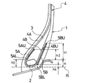
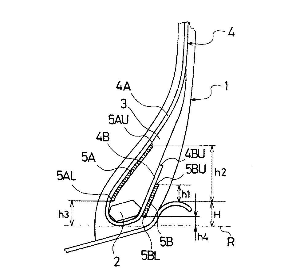
図1及び図2は、それぞれ本発明の第1及び第2実施形態からなる重荷重用空気入りラジアルタイヤのビード部を示す断面図である。図1及び図2において、ビード部1にはビードコア2が埋設され、ビードコア2の外周側にはビードフィラー3が配置されている。左右一対のビード部1,1間に装架されたカーカス層4は、その両端部がそれぞれビードコア2の廻りにタイヤ内側から外側へ巻き上げられている。即ち、カーカス層4はビードコア2を境にして本体部4Aと巻き上げ部4Bとから構成されている。そして、複数本のスチールコードを引き揃えてなる補強層は、ビードコア2を境にして内側補強層5Aと外側補強層5Bとに分割され、その内側補強層5Aがカーカス層4の本体部4Aとビードフィラー3との間に配置され、その外側補強層5Bがカーカス層4の巻き上げ部4Bよりタイヤ幅方向外側に配置されている。
【0014】
上記ビード部の補強構造において、カーカス層4の巻き上げ端4BUと内側補強層5Aの上端5AUと外側補強層5Bの上端5BUのタイヤ径方向の高さ位置は互いに相違しており、カーカス層4の巻き上げ端4BUは内側補強層5Aの上端5AUよりも高く、外側補強層5Bの上端5BUはカーカス層4の巻き上げ端4BUよりも高くなっている。
【0015】
ここで、リム径の基準位置Rからのリムフランジの高さをHとし、該リムフランジの頂点からの外側補強層5Bの上端5BUの高さをh1とし、該リムフランジの頂点からの内側補強層5Aの上端5AUの高さをh2とし、リム径の基準位置Rからの内側補強層5Aの下端5ALの高さをh3とし、リム径の基準位置Rからの外側補強層5Bの下端5BLの高さをh4としたとき、これら高さh1〜h4をリムフランジ高さHに対して適切に設定すると良い。但し、ここで言うリムとは、JATMA規定による標準リムである。
【0016】
図1の実施形態のように、内側補強層5Aの下端5ALをビードコア2の内側近傍に配置し、外側補強層5Bの下端5BLをビードコア2の外側近傍に配置した補強構造とする場合、下記条件を選択することにより、耐久性の向上効果が顕著に得られる。
1.90<h1/H<2.70
1.15<h2/H<1.85
0.50<h3/H<1.10
0.15<h4/H<0.70
【0017】
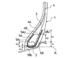
図2の実施形態のように、内側補強層5Aの下端5ALをビードコア2の内側近傍に配置し、外側補強層5Bをビードコア2の下側に廻り込ませて該外側補強層5Bの下端5BLをビードコア2の内側近傍に配置した補強構造とする場合、下記条件を選択することにより、耐久性の向上効果が顕著に得られる。
1.90<h1/H<2.70
1.15<h2/H<1.85
0.50<h3/H<1.10
0.10<h4/H<0.50
【0018】
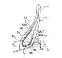
図3及び図4は、それぞれ本発明の第3及び第4実施形態からなる重荷重用空気入りラジアルタイヤのビード部を示す断面図である。図3及び図4において、ビード部1にはビードコア2が埋設され、ビードコア2の外周側にはビードフィラー3が配置されている。左右一対のビード部1,1間に装架されたカーカス層4は、その両端部がそれぞれビードコア2の廻りにタイヤ内側から外側へ巻き上げられている。即ち、カーカス層4はビードコア2を境にして本体部4Aと巻き上げ部4Bとから構成されている。そして、複数本のスチールコードを引き揃えてなる補強層は、ビードコア2を境にして内側補強層5Aと外側補強層5Bとに分割され、その内側補強層5Aがカーカス層4の本体部4Aとビードフィラー3との間に配置され、その外側補強層5Bがカーカス層4の巻き上げ部4Bよりタイヤ幅方向外側に配置されている。
【0019】
上記ビード部の補強構造において、カーカス層4の巻き上げ端4BUと内側補強層5Aの上端5AUと外側補強層5Bの上端5BUのタイヤ径方向の高さ位置は互いに相違しており、カーカス層4の巻き上げ端4BUは外側補強層5Bの上端5BUよりも高く、内側補強層5Aの上端5AUはカーカス層4の巻き上げ端4BUよりも高くなっている。
【0020】
ここで、リム径の基準位置Rからのリムフランジの高さをHとし、該リムフランジの頂点からの外側補強層5Bの上端5BUの高さをh1とし、該リムフランジの頂点からの内側補強層5Aの上端5AUの高さをh2とし、リム径の基準位置Rからの内側補強層5Aの下端5ALの高さをh3とし、リム径の基準位置Rからの外側補強層5Bの下端5BLの高さをh4としたとき、これら高さh1〜h4をリムフランジ高さHに対して適切に設定すると良い。但し、ここで言うリムとは、JATMA規定による標準リムである。
【0021】
図3の実施形態のように、内側補強層5Aの下端5ALをビードコア2の内側近傍に配置し、外側補強層5Bの下端5BLをビードコア2の外側近傍に配置した補強構造とする場合、下記条件を選択することにより、耐久性の向上効果が顕著に得られる。
0.40<h1/H<1.20
2.20<h2/H<2.90
0.50<h3/H<1.10
0.15<h4/H<0.70
【0022】
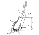
図4の実施形態のように、内側補強層5Aの下端5ALをビードコア2の内側近傍に配置し、外側補強層5Bをビードコア2の下側に廻り込ませて該外側補強層5Bの下端5BLをビードコア2の内側近傍に配置した補強構造とする場合、下記条件を選択することにより、耐久性の向上効果が顕著に得られる。
0.40<h1/H<1.20
2.20<h2/H<2.90
0.50<h3/H<1.10
0.10<h4/H<0.50
【0023】
上述した内側補強層5A及び外側補強層5Bについて、コード角度やコード打ち込み本数やコード撚り構造は特に限定されるものではない。
【0024】
ところで、上記タイヤはスチールコード補強層を内側補強層5Aと外側補強層5Bに分割した構成を備えているので、この分割構造を有効に利用し、それによって、耐久性の向上のみならず、軽量化や操縦安定性の向上を図ることが可能である。
【0025】
図5及び図6は、内側補強層5Aと外側補強層5Bを構成するスチールコードのタイヤ周方向に対する角度を説明するための展開図である。図5及び図6は、カーカス層4の本体部4Aと内側補強層5Aをビードコア2の左側に展開し、カーカス層4の巻き上げ部4Bと外側補強層5Bをビードコア2の右側に展開した状態を示している。図5及び図6において、内側補強層5Aのタイヤ周方向に対するコード絶対角度βと外側補強層5Bのタイヤ周方向に対するコード絶対角度αとは互いに異なっている。ここで、スチールコードの傾斜方向はいずれであっても良い。
【0026】
例えば、内側補強層5Aのコード絶対角度βを外側補強層5Bのコード絶対角度αよりも大きくし、そのコード絶対角度の差を5〜65度にすることにより、ビード部の耐久性を阻害することなく操縦安定性を向上することができる。なお、コード絶対角度の差が5度未満であると操縦安定性の向上効果が不十分になり、逆に65度超であるとビード部の耐久性が低下することになる。
【0027】
また、内側補強層5Aの単位幅当たりのコード打ち込み本数を外側補強層5Bの単位幅当たりのコード打ち込み本数よりも少なくした場合、操縦安定性やビード部の耐久性を良好にしたまま軽量化を図ることができる。
【0028】
更に、内側補強層5A及び外側補強層5Bのコード撚り構造を互いに異ならせ、内側補強層5Aのコードを外側補強層5Bのコードよりも軽くした場合、操縦安定性やビード部の耐久性を良好にしたまま軽量化を図ることができる。
【0029】
【実施例】
〔実験A〕
重荷重用空気入りラジアルタイヤ(サイズ:11R22.5)において、図1に示すビード部の補強構造を有し、内側補強層及び外側補強層の寸法を表1の通り種々異ならせた12種類の本発明タイヤ(実施例1〜12)、及び、図7に示すビード部の補強構造を有する従来タイヤ(従来例1)をそれぞれ製作した。従来例1において、補強層のカーカス層巻き上げ部側の上端の高さh5及びカーカス層本体部側の上端の高さh6を、リムフランジ高さHに対して、h5/H=2.30,h6/H=1.50とした。
【0030】
これら本発明タイヤ及び従来タイヤについて、以下の方法により耐久性を評価した。
【0031】
〔耐久性〕
リムサイズ:22.5×8.25、空気圧:700kPa(規定空気圧)、荷重:規定荷重の160%、速度:50km/hの条件で、各タイヤをドラム(直径:1700mm)上で回転し、ビード部が故障に至るまでの距離を測定した。評価結果は、従来例1を100とする指数により表1に示した。この指数値が大きいほどビード部の耐久性が優れている。
【0032】
【表1】
この結果から、本発明タイヤは従来タイヤに比べて耐久性が向上していることを確認した。特に、内側補強層及び外側補強層の寸法をリムフランジ高さHに対して適正化した実施例5〜8の本発明タイヤは耐久性の向上効果が顕著であった。
【0034】
〔実験B〕
重荷重用空気入りラジアルタイヤ(サイズ:11R22.5)において、図2に示すビード部の補強構造を有し、内側補強層及び外側補強層の寸法を表2の通り種々異ならせた12種類の本発明タイヤ(実施例13〜24)をそれぞれ製作し、実験Aと同じ方法により耐久性を評価し、その結果を従来例1を100とする指数により表2に示した。
【0035】
【表2】
この結果から、本発明タイヤは従来タイヤに比べて耐久性が向上していることを確認した。特に、内側補強層及び外側補強層の寸法をリムフランジ高さHに対して適正化した実施例17〜20の本発明タイヤは耐久性の向上効果が顕著であった。なお、実施例24の本発明タイヤは内側補強層及び外側補強層が重複しているため従来タイヤよりも重量が増加していた。
【0037】
〔実験C〕
重荷重用空気入りラジアルタイヤ(サイズ:11R22.5)において、図3に示すビード部の補強構造を有し、内側補強層及び外側補強層の寸法を表3の通り種々異ならせた4種類の本発明タイヤ(実施例29〜32)、8種類の比較タイヤ(比較例25〜28,33〜36)、及び、図8に示すビード部の補強構造を有する従来タイヤ(従来例2)をそれぞれ製作した。従来例2において、補強層のカーカス層巻き上げ部側の上端の高さh5及びカーカス層本体部側の上端の高さh6を、リムフランジ高さHに対して、h5/H=0.80,h6/H=2.50とした。
【0038】
これら本発明タイヤ、比較タイヤ及び従来タイヤについて、実験Aと同じ方法により耐久性を評価し、その結果を従来例2を100とする指数により表3に示した。
【0039】
【表3】
この結果から、本発明タイヤ及び比較タイヤは従来タイヤに比べて耐久性が向上していることを確認した。特に、内側補強層及び外側補強層の寸法をリムフランジ高さHに対して適正化した実施例29〜32の本発明タイヤは耐久性の向上効果が顕著であった。
【0041】
〔実験D〕
重荷重用空気入りラジアルタイヤ(サイズ:11R22.5)において、図4に示すビード部の補強構造を有し、内側補強層及び外側補強層の寸法を表4の通り種々異ならせた4種類の本発明タイヤ(実施例41〜44)及び8種類の比較タイヤ(比較例37〜40,45〜48)をそれぞれ製作し、実験Aと同じ方法により耐久性を評価し、その結果を従来例2を100とする指数により表4に示した。
【0042】
【表4】
この結果から、本発明タイヤ及び比較タイヤは従来タイヤに比べて耐久性が向上していることを確認した。特に、内側補強層及び外側補強層の寸法をリムフランジ高さHに対して適正化した実施例41〜44の本発明タイヤは耐久性の向上効果が顕著であった。なお、比較例48の比較タイヤは内側補強層及び外側補強層が重複しているため従来タイヤよりも重量が増加していた。
【0044】
〔実験E〕
重荷重用空気入りラジアルタイヤ(サイズ:11R22.5)において、図4に示すビード部の補強構造を有し、内側補強層及び外側補強層のコード角度、単位幅当たりのコード打ち込み本数、コード撚り構造を表5の通り種々異ならせた7種類の本発明タイヤ(実施例49〜55)、及び、図8に示すビード部の補強構造を有する従来タイヤ(従来例3)をそれぞれ製作した。従来例3において、補強層のコード角度を20度とし、コード打ち込み本数を23本/50mmとし、コード撚り構造を3+8×0.22とした。
【0045】
これら本発明タイヤ及び従来タイヤについて、実験Aと同じ方法により耐久性の試験を行い、その結果を従来例3を100とする指数により表5に示した。また、以下の方法によりタイヤ重量及び操縦安定性を評価した。
【0046】
〔タイヤ重量〕
各タイヤの重量を測定した。評価結果は、従来例3を100とする指数により表5に示した。この指数値が小さいほど軽量である。
【0047】
〔操縦安定性〕
リムサイズ:22.5×7.50、空気圧:700kPa(規定空気圧)、荷重:規定荷重の100%の条件で、各タイヤを車両に装着し、テストコースにおいて専門パネラー3名によるフィーリング評価を行った。評価結果は、従来例3を100とする指数にて示した。この指数値が大きいほど操縦安定性が優れている。
【0048】
【表5】
この結果から、内側補強層及び外側補強層の構造を互いに異ならせることにより、耐久性の向上のみならず、軽量化や操縦安定性の向上を図ることが可能であった。
【0050】
【発明の効果】
以上説明したように本発明によれば、スチールコードからなる補強層をビードコアを境にして内側補強層と外側補強層とに分割し、内側補強層をカーカス層の本体部とビードフィラーとの間に配置し、外側補強層をカーカス層の巻き上げ部よりタイヤ幅方向外側に配置したから、従来のようにカーカス層を包み込むようにスチールコード補強層を配置した場合に比べて、ビード部の耐久性を向上することができる。
【図面の簡単な説明】
【図1】本発明の第1実施形態からなる重荷重用空気入りラジアルタイヤのビード部を示す断面図である。
【図2】本発明の第2実施形態からなる重荷重用空気入りラジアルタイヤのビード部を示す断面図である。
【図3】本発明の第3実施形態からなる重荷重用空気入りラジアルタイヤのビード部を示す断面図である。
【図4】本発明の第4実施形態からなる重荷重用空気入りラジアルタイヤのビード部を示す断面図である。
【図5】本発明の空気入りタイヤにおける内側補強層と外側補強層を構成するスチールコードの配列の一例を示す展開図である。
【図6】本発明の空気入りタイヤにおける内側補強層と外側補強層を構成するスチールコードの配列の他の例を示す展開図である。
【図7】従来の重荷重用空気入りラジアルタイヤのビード部を示す断面図である。
【図8】従来の重荷重用空気入りラジアルタイヤのビード部の変形例を示す断面図である。
【符号の説明】
1 ビード部
2 ビードコア
3 ビードフィラー
4 カーカス層
4A カーカス層の本体部
4B カーカス層の巻き上げ部
4BU カーカス層の巻き上げ端
5A 内側補強層
5B 外側補強層
5AU 内側補強層の上端
5AL 内側補強層の下端
5BU 外側補強層の上端
5BL 外側補強層の下端
H リムフランジ高さ
R リム径の基準位置[0001]
BACKGROUND OF THE INVENTION
The present invention relates to a pneumatic tire having excellent durability, and more particularly, a pneumatic tire in which durability of a bead portion is improved by optimizing the arrangement and configuration of a reinforcing layer embedded in the bead portion. About.
[0002]
[Prior art]
In heavy-duty pneumatic radial tires, a reinforcement layer formed by aligning a plurality of steel cords can be embedded along the carcass layer in order to suppress separation starting from the winding end of the carcass layer in the bead portion. (For example, refer to Patent Document 1 and Patent Document 2).
[0003]
That is, in the conventional heavy-duty pneumatic radial tire, as shown in FIGS. 7 and 8, the
[0004]
By adding a steel cord reinforcing layer to the bead portion in this way, the bead portion is prevented from falling to the outside of the tire, the strain acting on the winding end of the carcass layer is reduced, and separation starting from the winding end is performed. Can be suppressed. However, when a steel cord reinforcing layer is added to the bead portion, a failure due to the reinforcing layer occurs, so that the durability improving effect is not always sufficient.
[0005]
[Patent Document 1]
Japanese Patent Laid-Open No. 11-20423 [Patent Document 2]
Japanese Patent Laid-Open No. 7-164837
[Problems to be solved by the invention]
An object of the present invention is to provide a pneumatic tire capable of improving the durability of a bead portion when the bead portion is reinforced by a steel cord reinforcing layer.
[0007]
[Means for Solving the Problems]
In order to achieve the above object, a pneumatic tire according to the present invention has a bead core embedded in each of a pair of left and right bead portions, a bead filler is disposed on the outer peripheral side of each bead core, and is mounted between the pair of left and right bead portions. In a pneumatic tire in which both ends of the carcass layer are wound around the bead core from the inside to the outside of the tire and a reinforcing layer formed by aligning a plurality of steel cords is embedded in the bead portion along the carcass layer, The reinforcing layer made of the steel cord is divided into an inner reinforcing layer and an outer reinforcing layer with the bead core as a boundary , and the inner reinforcing layer is disposed between the body portion of the carcass layer and the bead filler, and the outer reinforcing layer Is arranged on the outer side in the tire width direction from the rolled-up portion of the carcass layer , and further has a configuration to be described later .
[0008]
In this way, the steel cord reinforcing layer is divided into an inner reinforcing layer and an outer reinforcing layer with the bead core as a boundary , the inner reinforcing layer is disposed between the body portion of the carcass layer and the bead filler, and the outer reinforcing layer is the carcass layer. Since the steel cord reinforcing layer is disposed so as to wrap the carcass layer as in the conventional case, the durability of the bead portion can be improved. Further, in order to avoid an unnecessary increase in weight, the reinforcing layer made of steel cord is preferably arranged only in the above position.
[0009]
In the present invention, the height position in the tire radial direction of the rolled-up end of the carcass layer, the upper end of the inner reinforcing layer and the upper end of the outer reinforcing layer are different from each other, and the rolled-up end of the carcass layer is made higher than the upper end of the inner reinforcing layer, The upper end of the outer reinforcing layer is made higher than the rolled-up end of the carcass layer . Alternatively, the height of the upper end of the carcass layer, the upper end of the inner reinforcing layer, and the upper end of the outer reinforcing layer in the tire radial direction is made different from each other, and the rolled up end of the carcass layer is made higher than the upper end of the outer reinforcing layer. The upper end of the layer is made higher than the rolled-up end of the carcass layer . In either case, the change in rigidity of the bead portion becomes smooth, which is advantageous in terms of durability.
[0010]
The height of the rim flange from the reference position of the rim diameter is H, the height of the upper end of the outer reinforcing layer from the apex of the rim flange is h1, and the height of the upper end of the inner reinforcing layer from the apex of the rim flange is When the height is h2, the height of the lower end of the inner reinforcing layer from the reference position of the rim diameter is h3, and the height of the lower end of the outer reinforcing layer from the reference position of the rim diameter is h4, these heights h1 is set appropriately ~h4 against the rim flange height H.
The height positions in the tire radial direction of the rolled-up end of the carcass layer, the upper end of the inner reinforcing layer, and the upper end of the outer reinforcing layer are made different from each other, and the rolled-up end of the carcass layer is made higher than the upper end of the inner reinforcing layer. In the case of having a reinforcing structure in which the upper end is made higher than the rolled-up end of the carcass layer, while the lower end of the inner reinforcing layer is arranged in the vicinity of the inner side of the bead core and the lower end of the outer reinforcing layer is arranged in the vicinity of the outer side of the bead core. <H1 / H <2.70, 1.15 <h2 / H <1.85, 0.50 <h3 / H <1.10, 0.15 <h4 / H <0.70 Is preferred.
The height positions in the tire radial direction of the rolled-up end of the carcass layer, the upper end of the inner reinforcing layer, and the upper end of the outer reinforcing layer are made different from each other, and the rolled-up end of the carcass layer is made higher than the upper end of the inner reinforcing layer. While the upper end is made higher than the rolled-up end of the carcass layer, the lower end of the inner reinforcing layer is arranged in the vicinity of the inner side of the bead core, and the outer reinforcing layer is wrapped around the lower side of the bead core so that the lower end of the outer reinforcing layer is placed on the bead core. When the reinforcing structure is disposed in the vicinity of the inside, 1.90 <h1 / H <2.70, 1.15 <h2 / H <1.85, 0.50 <h3 / H <1.10, 0.10 It is preferable that the condition of <h4 / H <0.50 is satisfied.
The height positions in the tire radial direction of the rolled-up end of the carcass layer, the upper end of the inner reinforcing layer, and the upper end of the outer reinforcing layer are made different from each other, the rolled-up end of the carcass layer is made higher than the upper end of the outer reinforcing layer, When the upper end is made higher than the rolled-up end of the carcass layer, the lower end of the inner reinforcing layer is disposed in the vicinity of the inner side of the bead core, and the lower end of the outer reinforcing layer is disposed in the vicinity of the outer side of the bead core. <H1 / H <1.20, 2.20 <h2 / H <2.90, 0.50 <h3 / H <1.10, 0.15 <h4 / H <0.70 And
The height positions in the tire radial direction of the rolled-up end of the carcass layer, the upper end of the inner reinforcing layer, and the upper end of the outer reinforcing layer are made different from each other, the rolled-up end of the carcass layer is made higher than the upper end of the outer reinforcing layer, While the upper end is made higher than the rolled-up end of the carcass layer, the lower end of the inner reinforcing layer is arranged in the vicinity of the inner side of the bead core, and the outer reinforcing layer is wrapped around the lower side of the bead core so that the lower end of the outer reinforcing layer is placed on the bead core. When the reinforcing structure is disposed in the vicinity of the inner side, 0.40 <h1 / H <1.20, 2.20 <h2 / H <2.90, 0.50 <h3 / H <1.10, 0.10 <H4 / H <0.50 is satisfied.
[0011]
In the present invention, since the steel cord reinforcing layer is divided into the inner reinforcing layer and the outer reinforcing layer, the divided structure is effectively used, thereby improving the durability as well as reducing the weight and maneuvering. It is also possible to improve stability. More specifically, the cord absolute angles with respect to the tire circumferential direction of the inner reinforcing layer and the outer reinforcing layer may be different from each other. In this case, the difference in the absolute cord angle between the inner reinforcing layer and the outer reinforcing layer with respect to the tire circumferential direction is preferably 5 to 65 degrees. Further, the number of cords driven per unit width and the cord twist structure of the inner reinforcing layer and the outer reinforcing layer may be different from each other.
[0012]
DETAILED DESCRIPTION OF THE INVENTION
Hereinafter, embodiments of the present invention will be described with reference to the accompanying drawings. In each drawing, the same constituent elements are given the same reference numerals, and redundant description is omitted.
[0013]
1 and 2 are cross-sectional views showing bead portions of heavy-duty pneumatic radial tires according to the first and second embodiments of the present invention, respectively. 1 and 2, a
[0014]
In the reinforcement structure of the bead part, the height positions in the tire radial direction of the winding end 4BU of the
[0015]
Here, the height of the rim flange from the reference position R of the rim diameter is H, the height of the upper end 5BU of the outer reinforcing
[0016]
In the case of a reinforcing structure in which the lower end 5AL of the inner reinforcing
1.90 <h1 / H <2.70
1.15 <h2 / H <1.85
0.50 <h3 / H <1.10
0.15 <h4 / H <0.70
[0017]
As shown in the embodiment of FIG. 2, the lower end 5AL of the inner reinforcing
1.90 <h1 / H <2.70
1.15 <h2 / H <1.85
0.50 <h3 / H <1.10
0.10 <h4 / H <0.50
[0018]
3 and 4 are cross-sectional views showing the bead portions of the heavy-duty pneumatic radial tire according to the third and fourth embodiments of the present invention, respectively. 3 and 4, a
[0019]
In the reinforcement structure of the bead part, the height positions in the tire radial direction of the winding end 4BU of the
[0020]
Here, the height of the rim flange from the reference position R of the rim diameter is H, the height of the upper end 5BU of the outer reinforcing
[0021]
When the reinforcing structure in which the lower end 5AL of the inner reinforcing
0.40 <h1 / H <1.20
2.20 <h2 / H <2.90
0.50 <h3 / H <1.10
0.15 <h4 / H <0.70
[0022]
As shown in the embodiment of FIG. 4, the lower end 5AL of the inner reinforcing
0.40 <h1 / H <1.20
2.20 <h2 / H <2.90
0.50 <h3 / H <1.10
0.10 <h4 / H <0.50
[0023]
For the inner reinforcing
[0024]
By the way, the tire has a structure in which the steel cord reinforcing layer is divided into the inner reinforcing
[0025]
5 and 6 are development views for explaining the angles of the steel cords constituting the inner reinforcing
[0026]
For example, the cord absolute angle β of the inner reinforcing
[0027]
In addition, when the number of cords driven per unit width of the inner reinforcing
[0028]
Further, when the cord reinforced structures of the inner reinforcing
[0029]
【Example】
[Experiment A]
12 heavy-duty pneumatic radial tires (size: 11R22.5) having the reinforcement structure of the bead portion shown in FIG. 1 and different dimensions of the inner and outer reinforcing layers as shown in Table 1. Invention tires (Examples 1 to 12) and conventional tires (Conventional Example 1) having a bead portion reinforcing structure shown in FIG. 7 were produced. In Conventional Example 1, the height h5 of the upper end of the reinforcing layer on the side of the rolled-up portion of the carcass layer and the height h6 of the upper end on the side of the main body of the carcass layer are set to h5 / H = 2.30 with respect to the height of the rim flange H. h6 / H = 1.50.
[0030]
The durability of these tires of the present invention and conventional tires was evaluated by the following method.
[0031]
〔durability〕
Each tire is rotated on a drum (diameter: 1700 mm) under the conditions of rim size: 22.5 × 8.25, air pressure: 700 kPa (specified air pressure), load: 160% of the specified load, and speed: 50 km / h. The distance until the part failed was measured. The evaluation results are shown in Table 1 using an index with Conventional Example 1 as 100. The larger the index value, the better the durability of the bead portion.
[0032]
[Table 1]
From this result, it was confirmed that the tire of the present invention has improved durability compared to the conventional tire. In particular, the tires according to Examples 5 to 8 in which the dimensions of the inner reinforcing layer and the outer reinforcing layer were optimized with respect to the rim flange height H were significantly improved in durability.
[0034]
[Experiment B]
12 heavy-duty pneumatic radial tires (size: 11R22.5) having the reinforcement structure of the bead portion shown in FIG. 2 and having different dimensions of the inner and outer reinforcing layers as shown in Table 2 Inventive tires (Examples 13 to 24) were produced, and the durability was evaluated by the same method as in Experiment A. The results are shown in Table 2 using the index of Conventional Example 1 as 100.
[0035]
[Table 2]
From this result, it was confirmed that the tire of the present invention has improved durability compared to the conventional tire. In particular, the tires according to Examples 17 to 20 in which the dimensions of the inner reinforcing layer and the outer reinforcing layer were optimized with respect to the rim flange height H were significantly improved in durability. In addition, since the inner side reinforcement layer and the outer side reinforcement layer overlapped the tire of this invention of Example 24, the weight increased from the conventional tire.
[0037]
[Experiment C]
Heavy duty pneumatic radial tire: in (size 11R22.5), has a reinforcing structure of the bead portion shown in FIG. 3, four types of book dimensions of the inner reinforcing layer and an outer reinforcing layer is made different variety as shown in Table 3 Invention tires (Examples 29 to 32), 8 types of comparative tires (Comparative Examples 25 to 28 , 33 to 36) , and a conventional tire (Conventional Example 2) having a reinforcement structure of the bead portion shown in FIG. did. In Conventional Example 2, the height h5 of the upper end of the reinforcing layer on the carcass layer winding portion side and the height h6 of the upper end on the carcass layer main body side are set to h5 / H = 0.80 with respect to the rim flange height H. h6 / H = 2.50.
[0038]
The durability of these tires of the present invention, comparative tires and conventional tires was evaluated by the same method as in Experiment A, and the results are shown in Table 3 using the index of Conventional Example 2 as 100.
[0039]
[Table 3]
From these results, it was confirmed that the tires of the present invention and the comparative tire had improved durability compared to the conventional tire. In particular, the tires according to Examples 29 to 32 in which the dimensions of the inner reinforcing layer and the outer reinforcing layer were optimized with respect to the rim flange height H showed a remarkable effect of improving durability.
[0041]
[Experiment D]
Heavy duty pneumatic radial tire: in (size 11R22.5), has a reinforcing structure of the bead portion shown in FIG. 4, four kinds of book dimensions of the inner reinforcing layer and an outer reinforcing layer is made different variety as shown in Table 4 Inventive tires (Examples 41 to 44) and 8 types of comparative tires (Comparative Examples 37 to 40, 45 to 48) were manufactured, and durability was evaluated by the same method as in Experiment A. The results are shown in Table 4 with an index of 100.
[0042]
[Table 4]
From these results, it was confirmed that the tires of the present invention and the comparative tire had improved durability compared to the conventional tire. In particular, the tires according to Examples 41 to 44 in which the dimensions of the inner reinforcing layer and the outer reinforcing layer were optimized with respect to the rim flange height H were significantly improved in durability. In the comparative tire of Comparative Example 48, the inner reinforcing layer and the outer reinforcing layer overlap each other, so that the weight is increased as compared with the conventional tire.
[0044]
[Experiment E]
In the heavy-duty pneumatic radial tire (size: 11R22.5), it has the reinforcement structure of the bead portion shown in FIG. 4, the cord angle of the inner reinforcement layer and the outer reinforcement layer, the number of cords driven per unit width, and the cord twist structure 7 tires according to the present invention (Examples 49 to 55) having different configurations as shown in Table 5 and a conventional tire (Conventional Example 3) having a bead portion reinforcing structure shown in FIG. In Conventional Example 3, the cord angle of the reinforcing layer was 20 degrees, the number of cords to be driven was 23/50 mm, and the cord twist structure was 3 + 8 × 0.22.
[0045]
These tires of the present invention and conventional tires were subjected to durability tests by the same method as in Experiment A, and the results are shown in Table 5 using an index with Conventional Example 3 being 100. In addition, tire weight and steering stability were evaluated by the following methods.
[0046]
[Tire weight]
The weight of each tire was measured. The evaluation results are shown in Table 5 by using an index with Conventional Example 3 as 100. The smaller the index value, the lighter the weight.
[0047]
[Maneuvering stability]
Rim size: 22.5 x 7.50, air pressure: 700 kPa (regulated air pressure), load: 100% of the specified load, each tire is mounted on the vehicle, and a feeling evaluation is conducted by 3 expert panelists on the test course It was. The evaluation results are shown as an index with Conventional Example 3 as 100. The larger the index value, the better the steering stability.
[0048]
[Table 5]
From this result, it was possible not only to improve the durability but also to reduce the weight and improve the steering stability by making the structures of the inner reinforcing layer and the outer reinforcing layer different from each other.
[0050]
【The invention's effect】
As described above, according to the present invention, the reinforcing layer made of steel cord is divided into the inner reinforcing layer and the outer reinforcing layer with the bead core as a boundary , and the inner reinforcing layer is separated between the main body portion of the carcass layer and the bead filler. Because the outer reinforcement layer is placed outside the carcass layer roll-up part in the tire width direction, the durability of the bead part is higher than when the steel cord reinforcement layer is placed so as to wrap the carcass layer as before. Can be improved.
[Brief description of the drawings]
FIG. 1 is a cross-sectional view showing a bead portion of a heavy duty pneumatic radial tire according to a first embodiment of the present invention.
FIG. 2 is a cross-sectional view showing a bead portion of a heavy duty pneumatic radial tire according to a second embodiment of the present invention.
FIG. 3 is a cross-sectional view showing a bead portion of a heavy duty pneumatic radial tire according to a third embodiment of the present invention.
FIG. 4 is a cross-sectional view showing a bead portion of a heavy duty pneumatic radial tire according to a fourth embodiment of the present invention.
FIG. 5 is a development view showing an example of an arrangement of steel cords constituting the inner reinforcing layer and the outer reinforcing layer in the pneumatic tire of the present invention.
FIG. 6 is a development view showing another example of the arrangement of steel cords constituting the inner reinforcing layer and the outer reinforcing layer in the pneumatic tire of the present invention.
FIG. 7 is a cross-sectional view showing a bead portion of a conventional heavy-duty pneumatic radial tire.
FIG. 8 is a cross-sectional view showing a modified example of a bead portion of a conventional heavy-duty pneumatic radial tire.
[Explanation of symbols]
DESCRIPTION OF SYMBOLS 1
Claims (9)
1.90<h1/H<2.70
1.15<h2/H<1.85
0.50<h3/H<1.10
0.15<h4/H<0.70It has a reinforcing structure in which the lower end of the inner reinforcing layer is disposed in the vicinity of the inside of the bead core, and the lower end of the outer reinforcing layer is disposed in the vicinity of the outer side of the bead core, and the height of the rim flange from the reference position of the rim diameter is set. H, the height of the upper end of the outer reinforcing layer from the apex of the rim flange is h1, the height of the upper end of the inner reinforcing layer from the apex of the rim flange is h2, and from the reference position of the rim diameter the height of the lower end of the inner reinforcing layer and h3, when the height of the lower end of the outer reinforcing layer from a reference position of the rim diameter and h4, pneumatic according to claim 1 which satisfies the following conditions tire.
1.90 <h1 / H <2.70
1.15 <h2 / H <1.85
0.50 <h3 / H <1.10
0.15 <h4 / H <0.70
1.90<h1/H<2.70
1.15<h2/H<1.85
0.50<h3/H<1.10
0.10<h4/H<0.50A reinforcing structure in which a lower end of the inner reinforcing layer is disposed in the vicinity of the inner side of the bead core, and the outer reinforcing layer is placed under the bead core so that the lower end of the outer reinforcing layer is disposed in the vicinity of the inner side of the bead core. The height of the rim flange from the reference position of the rim diameter is H, the height of the upper end of the outer reinforcing layer from the apex of the rim flange is h1, and the height of the inner reinforcing layer from the apex of the rim flange is The height of the upper end is h2, the height of the lower end of the inner reinforcing layer from the reference position of the rim diameter is h3, and the height of the lower end of the outer reinforcing layer from the reference position of the rim diameter is h4. The pneumatic tire according to claim 1 , wherein the following conditions are satisfied.
1.90 <h1 / H <2.70
1.15 <h2 / H <1.85
0.50 <h3 / H <1.10
0.10 <h4 / H <0.50
0.40<h1/H<1.20
2.20<h2/H<2.90
0.50<h3/H<1.10
0.15<h4/H<0.70 A bead core is embedded in each of the pair of left and right bead portions, a bead filler is disposed on the outer peripheral side of each bead core, and both end portions of the carcass layer mounted between the pair of left and right bead portions are disposed around the bead core from the inside of the tire. In a pneumatic tire in which a reinforcing layer formed by aligning a plurality of steel cords is rolled up outside and embedded in the bead portion along the carcass layer, the reinforcing layer made of the steel cord is arranged inside the bead core as a boundary. The reinforcing layer and the outer reinforcing layer are divided, the inner reinforcing layer is disposed between the main body portion of the carcass layer and the bead filler, and the outer reinforcing layer is disposed on the outer side in the tire width direction from the rolled-up portion of the carcass layer. , Different height positions in the tire radial direction of the winding end of the carcass layer, the upper end of the inner reinforcing layer and the upper end of the outer reinforcing layer, Winding ends of the serial carcass layer higher than the upper end of the outer reinforcing layer, inside the vicinity of the upper end of the inner reinforcing layer while higher than up end of the carcass layer, the bead core the lower end of the inner reinforcing layer And the lower end of the outer reinforcing layer is arranged in the vicinity of the outside of the bead core, and the height of the rim flange from the reference position of the rim diameter is H, and the outer side from the apex of the rim flange The height of the upper end of the reinforcing layer is h1, the height of the upper end of the inner reinforcing layer from the apex of the rim flange is h2, and the height of the lower end of the inner reinforcing layer from the reference position of the rim diameter is h3. And a pneumatic tire that satisfies the following conditions when the height of the lower end of the outer reinforcing layer from the reference position of the rim diameter is h4.
0.40 <h1 / H <1.20
2.20 <h2 / H <2.90
0.50 <h3 / H <1.10
0.15 <h4 / H <0.70
0.40<h1/H<1.20
2.20<h2/H<2.90
0.50<h3/H<1.10
0.10<h4/H<0.50 A bead core is embedded in each of the pair of left and right bead portions, a bead filler is disposed on the outer peripheral side of each bead core, and both end portions of the carcass layer mounted between the pair of left and right bead portions are disposed around the bead core from the inside of the tire. In a pneumatic tire in which a reinforcing layer formed by aligning a plurality of steel cords is rolled up outside and embedded in the bead portion along the carcass layer, the reinforcing layer made of the steel cord is arranged inside the bead core as a boundary. The reinforcing layer and the outer reinforcing layer are divided, the inner reinforcing layer is disposed between the main body portion of the carcass layer and the bead filler, and the outer reinforcing layer is disposed on the outer side in the tire width direction from the rolled-up portion of the carcass layer. , Different height positions in the tire radial direction of the winding end of the carcass layer, the upper end of the inner reinforcing layer and the upper end of the outer reinforcing layer, Winding ends of the serial carcass layer higher than the upper end of the outer reinforcing layer, inside the vicinity of the upper end of the inner reinforcing layer while higher than up end of the carcass layer, the bead core the lower end of the inner reinforcing layer And a reinforcing structure in which the outer reinforcing layer is placed under the bead core and the lower end of the outer reinforcing layer is arranged in the vicinity of the inner side of the bead core, and the rim flange from the reference position of the rim diameter is provided. The height is H, the height of the upper end of the outer reinforcing layer from the apex of the rim flange is h1, the height of the upper end of the inner reinforcing layer from the apex of the rim flange is h2, and the rim diameter A pneumatic tire that satisfies the following conditions when the height of the lower end of the inner reinforcing layer from the reference position is h3 and the height of the lower end of the outer reinforcing layer from the reference position of the rim diameter is h4.
0.40 <h1 / H <1.20
2.20 <h2 / H <2.90
0.50 <h3 / H <1.10
0.10 <h4 / H <0.50
Priority Applications (1)
| Application Number | Priority Date | Filing Date | Title |
|---|---|---|---|
| JP2002295999A JP4255262B2 (en) | 2002-10-09 | 2002-10-09 | Pneumatic tire |
Applications Claiming Priority (1)
| Application Number | Priority Date | Filing Date | Title |
|---|---|---|---|
| JP2002295999A JP4255262B2 (en) | 2002-10-09 | 2002-10-09 | Pneumatic tire |
Publications (2)
| Publication Number | Publication Date |
|---|---|
| JP2004130881A JP2004130881A (en) | 2004-04-30 |
| JP4255262B2 true JP4255262B2 (en) | 2009-04-15 |
Family
ID=32286096
Family Applications (1)
| Application Number | Title | Priority Date | Filing Date |
|---|---|---|---|
| JP2002295999A Expired - Fee Related JP4255262B2 (en) | 2002-10-09 | 2002-10-09 | Pneumatic tire |
Country Status (1)
| Country | Link |
|---|---|
| JP (1) | JP4255262B2 (en) |
Families Citing this family (3)
| Publication number | Priority date | Publication date | Assignee | Title |
|---|---|---|---|---|
| JP6238708B2 (en) * | 2013-11-29 | 2017-11-29 | 東洋ゴム工業株式会社 | Pneumatic tire and manufacturing method thereof |
| CN103738122B (en) * | 2014-01-07 | 2016-03-23 | 中策橡胶集团有限公司 | All-steel radial tyre of a kind of two layers of U-shaped steel wire reinforced bead and preparation method thereof |
| JP2023069500A (en) | 2021-11-05 | 2023-05-18 | Toyo Tire株式会社 | pneumatic tire |
-
2002
- 2002-10-09 JP JP2002295999A patent/JP4255262B2/en not_active Expired - Fee Related
Also Published As
| Publication number | Publication date |
|---|---|
| JP2004130881A (en) | 2004-04-30 |
Similar Documents
| Publication | Publication Date | Title |
|---|---|---|
| JP5049050B2 (en) | Heavy duty tire | |
| JP4464700B2 (en) | Pneumatic tire and manufacturing method thereof | |
| EP2246202B1 (en) | Floating two-ply tire | |
| JP6954060B2 (en) | Pneumatic tires | |
| JP2007015638A (en) | Pneumatic tire | |
| JP3071923B2 (en) | Pneumatic radial tire for heavy loads | |
| JP4510970B2 (en) | Pneumatic tire | |
| JP4255262B2 (en) | Pneumatic tire | |
| JP4891604B2 (en) | Pneumatic tire | |
| JP4410892B2 (en) | Pneumatic tire | |
| JP4606184B2 (en) | Pneumatic tire | |
| JP3647977B2 (en) | Heavy duty pneumatic radial tire | |
| JP3715058B2 (en) | Pneumatic tire | |
| WO2005037575A1 (en) | Pneumatic radial tire | |
| JP4367914B2 (en) | Tire bead core and pneumatic tire | |
| JP7067055B2 (en) | Pneumatic tires | |
| JP2004182036A (en) | Run flat radial-ply tire | |
| JP4236324B2 (en) | Heavy duty pneumatic radial tire | |
| EP2159078B1 (en) | Modular ply tire with dissimilar materials | |
| JP4615654B2 (en) | Pneumatic tire | |
| JP2001191724A (en) | Pneumatic tire excellent in bead part durability | |
| JP3377453B2 (en) | Heavy duty tire | |
| JP2000264014A (en) | Radial tire for heavy load | |
| JP5040232B2 (en) | Pneumatic tire | |
| JP2009241720A (en) | Pneumatic tire |
Legal Events
| Date | Code | Title | Description |
|---|---|---|---|
| A621 | Written request for application examination |
Free format text: JAPANESE INTERMEDIATE CODE: A621 Effective date: 20050913 |
|
| A977 | Report on retrieval |
Free format text: JAPANESE INTERMEDIATE CODE: A971007 Effective date: 20081010 |
|
| A131 | Notification of reasons for refusal |
Free format text: JAPANESE INTERMEDIATE CODE: A131 Effective date: 20081021 |
|
| A521 | Written amendment |
Free format text: JAPANESE INTERMEDIATE CODE: A523 Effective date: 20081217 |
|
| TRDD | Decision of grant or rejection written | ||
| A01 | Written decision to grant a patent or to grant a registration (utility model) |
Free format text: JAPANESE INTERMEDIATE CODE: A01 Effective date: 20090120 |
|
| A01 | Written decision to grant a patent or to grant a registration (utility model) |
Free format text: JAPANESE INTERMEDIATE CODE: A01 |
|
| A61 | First payment of annual fees (during grant procedure) |
Free format text: JAPANESE INTERMEDIATE CODE: A61 Effective date: 20090127 |
|
| FPAY | Renewal fee payment (event date is renewal date of database) |
Free format text: PAYMENT UNTIL: 20120206 Year of fee payment: 3 |
|
| R150 | Certificate of patent or registration of utility model |
Free format text: JAPANESE INTERMEDIATE CODE: R150 |
|
| FPAY | Renewal fee payment (event date is renewal date of database) |
Free format text: PAYMENT UNTIL: 20120206 Year of fee payment: 3 |
|
| FPAY | Renewal fee payment (event date is renewal date of database) |
Free format text: PAYMENT UNTIL: 20120206 Year of fee payment: 3 |
|
| FPAY | Renewal fee payment (event date is renewal date of database) |
Free format text: PAYMENT UNTIL: 20120206 Year of fee payment: 3 |
|
| FPAY | Renewal fee payment (event date is renewal date of database) |
Free format text: PAYMENT UNTIL: 20130206 Year of fee payment: 4 |
|
| FPAY | Renewal fee payment (event date is renewal date of database) |
Free format text: PAYMENT UNTIL: 20130206 Year of fee payment: 4 |
|
| FPAY | Renewal fee payment (event date is renewal date of database) |
Free format text: PAYMENT UNTIL: 20130206 Year of fee payment: 4 |
|
| R250 | Receipt of annual fees |
Free format text: JAPANESE INTERMEDIATE CODE: R250 |
|
| R250 | Receipt of annual fees |
Free format text: JAPANESE INTERMEDIATE CODE: R250 |
|
| LAPS | Cancellation because of no payment of annual fees |