JP4253106B2 - Continuous forms and how to use them - Google Patents
Continuous forms and how to use them Download PDFInfo
- Publication number
- JP4253106B2 JP4253106B2 JP2000193758A JP2000193758A JP4253106B2 JP 4253106 B2 JP4253106 B2 JP 4253106B2 JP 2000193758 A JP2000193758 A JP 2000193758A JP 2000193758 A JP2000193758 A JP 2000193758A JP 4253106 B2 JP4253106 B2 JP 4253106B2
- Authority
- JP
- Japan
- Prior art keywords
- page
- continuous
- paper
- printer
- thin
- Prior art date
- Legal status (The legal status is an assumption and is not a legal conclusion. Google has not performed a legal analysis and makes no representation as to the accuracy of the status listed.)
- Expired - Fee Related
Links
Images


Description
【0001】
【発明の属する技術分野】
本発明は、重ね合せ片等によって幅方向で厚み差のある連続帳票及びその使用方法に関するものである。
【0002】
【従来の技術】
昨今、通販会社等では、従来、別々に用意していた配送伝票と、商品明細書リスト帳票等とを一体化する動きがある。この理由は、
( i)媒体そのもののコストダウンをはかれる、
(ii )印字作業の効率化によるコストダウンや納期短縮をはかれる、
(iii)誤発送の撲滅によるコストダウンや企業イメージの向上等をはかれる、
等々のメリットがあるからである。
【0003】
しかし、配送伝票は、例えば、段ボール等の荷物に直接貼ることができなければ、印字した紙の裏面に糊を塗って貼るという作業が別途必要となるために、前述したメリットを得ることができなくなることから、裏面にタック紙が必要である。
一方、商品明細書リスト帳票は、単なるリストであるために、上質紙又は各種プリンタに適合するプリンタ用紙単一で良く、タック紙は必要ない。
【0004】
これらを一体化する簡単な方法は、商品明細書リスト帳票の裏面にもタック紙を設けておき、タック紙として使わなければよい。この方法であれば、タック紙に印刷、加工を行うだけでよく、一体化するにあたっても、特別の設備は必要ない。
【0005】
しかし、一般的には、商品明細書リスト帳票の方が、配送伝票よりも数倍以上大きく、かつ、上質紙やプリンタ用紙よりも、タック紙の方が数倍高いことから、媒体そのもののコストダウンは図れず、また、資材を多く使うことから、環境保護の観点からも、企業イメージの悪化にもつながりかねない。
【0006】
以上の理由から、現在、重ね合せ片付き連続帳票が実用化されている。
図3は、重ね合せ片付き連続帳票の一般的な構成を示す図である。
この重ね合せ片付き連続帳票10は、配送伝票10Aと、商品明細書リスト帳票10Bとが一体化されたものである。
配送伝票10Aは、上質紙やプリンタ用紙等の基材11の裏面の一部に、疑似接着剤等の剥離構造12を介して、タック紙13が設けられている。
タック紙13は、上質紙等の上紙14と、その裏面に形成れた粘着剤15と、粘着剤15に剥離可能に貼付された剥離紙16等とを備えている。剥離構造12及びタック紙13からなる重ね合せ片は、連続帳票の流れ方向に、実質的な隙間が無い状態で、その重ね合せ片が略全面を接着又は擬似接着した状態で貼り込まれている。
一方、商品明細書リスト帳票10Bは、上質紙やプリンタ用紙等の基材11のみからなり、配送伝票10Aの基材11の残りの一部が用いられている。
【0007】
この重ね合せ片付き連続帳票10は、図2に示すように、基材11にタック紙13を貼り込むことによって、幅方向に大きな厚みの差が生じることが理解できる。これは、数百〜数千ページを折り畳んでブロック状にした場合にも、図4(a)に示すのように、倒れた状態となるために、あまり多くの量を1箱に詰め込むことはできない。
【0008】
そして、1箱に多くを詰め込むことができないということは、業務量が多い通販会社等では、プリンタに用紙を何度もかけ替えなくてはならない、ということになり、作業性が悪化することが考えられる。
ただし、例えば、高速NIP(ノンインパクトプリンタ)と呼ばれるプリンタには、オートロードという自動給紙機構が付いており、安定的に用紙がセットできさえすれば、作業員の肉体的な負荷は必ずしも大きくはない。
【0009】
また、図4(b)に示すように、箱内に高さ調整用のスペーサー20等を使用して、幅方向の厚み差を吸収すれば、一般的な連続帳票と同程度の箱入り目が確保できるため、コストダウン効果等のメリットを多く享受できることになる。
【0010】
【発明が解決しようとする課題】
そこで、本件発明者は、重ね合せ片付き連続帳票10を実用化させる上で重要な点は、その形態から来る「オートロード適性」の低さを、どのように克服するかという点に着目した。
【0011】
以下に、本発明が解決しようとするオートロード適性について説明する。
オートロード機構は、プリンタ機種ごと、プリンタメーカーごとに異なっているために、プリンタ側から見て最も望ましい用紙物性を数値化することは困難である。
しかし、重ね合せ片付き連続帳票としては、概して、次の物性が重要と考えられる。
(a)幅方向の厚みの差
(b)幅方向のカール
【0012】
もちろん、この2点以外の物性については、まず、プリンタごとに規定され、推奨される用紙規格に合致していることが望ましい。
【0013】
次に、代表的なプリンタとして、昭和情報機器・SX7300のオートロード機構を例にして説明する。
(I) まず、印字したい帳票を、天地サイズに合わせてテーブルの所定位置に置く。このときに、両ピン孔を、テーブルにあるピントラクタに合わせて用紙幅をあわせる。
(II) オートロードを開始すると、テーブルの下端側を支点にして、先端が上昇し、上部にある用紙フィード用のピントラクタによってピン孔を送る。
(III ) ピン孔で送りはじめると、フィード用のニップローラで用紙を挟み込んで、スタッカに用紙が供給されるまで、自動的にフィードしていく。これで、オートロードは完了となる。
【0014】
そして、これらの機構のうち、(I)では、(b)の「幅方向のカール」が重要であり、(III )では、(a)の「幅方向の厚み差」が重要になる。
(b)の「幅方向のカール」が大きいと、テーブルにあるピントラクタに帳票のピン孔を合わせることができないため、用紙セットが困難になり、(a)の「幅方向の厚み差」が大きいと、ニップローラでかかる圧力が、極端に厚い重ね合せ片側だけになり、蛇行しやすくなるという問題がある。
【0015】
実際には、ピンで送っているために、蛇行まで至らない場合が多いが、プリンタの調整状態、ニップローラ等の機構を構成する部材の摩擦度などによって、ピン孔が歪んだりしてジャムを発生して、オートロード不良に至る場合が散見される。
この連続帳票は、ピン孔で送る機構のため、オートロードで用紙セットに成功すれば、よほどのことがない限り、1箱単位の印字は可能である。カールや厚み差についても同様である。
【0016】
本発明の目的は、幅方向に厚み差のある連続帳票のメリットを最大限に生かしながら、これらの課題を解決して、オートロード適性に優れた連続帳票及びその使用方法を提供し、良好な印字業務を構築することである。
【0017】
【課題を解決するための手段】
前記課題を解決するために、請求項1の発明は、厚みが異なる厚手帳票部と薄手帳票部とが幅方向に連接され、流れ方向に複数ページ連続する連続帳票において、先頭側の1ページ目には、前記薄手帳票部(10B−1)のみ備え、前記薄手帳票部は、前記先頭側の1ページ目(P1)と2ページ目(P2)とを折り合わせてあること、を特徴とする連続帳票である。
【0019】
請求項2の発明は、請求項1に記載の連続帳票において、前記薄手帳票部(10B)は、前記先頭側の1ページ目(P1)と2ページ目(P2)とを折り合わせた状態で、接着又は擬似接着してあること、を特徴とする連続帳票である。
【0021】
請求項3の発明は、厚みが異なる厚手帳票部と薄手帳票部とが幅方向に連接され、流れ方向に複数ページ連続する連続帳票の使用方法において、前記厚手帳票部の先頭側の1ページ目を除去し、前記薄手帳票部の先頭側の1ページ目を2ページ目に重ね合わせて、プリンタにセッティングすること、を特徴とする連続帳票の使用方法である。
【0022】
請求項4の発明は、厚みが異なる厚手帳票部と薄手帳票部とが幅方向に連接され、流れ方向に複数ページ連続する連続帳票であって、先頭側の1ページ目には、前記薄手帳票部のみ備える連続帳票の使用方法において、前記薄手帳票部の先頭側の1ページ目を2ページ目に重ね合わせて、プリンタにセッティングすること、を特徴とする連続帳票の使用方法である。
【0023】
【発明の実施の形態】
以下、図面などを参照しながら、本発明の実施の形態をあげて、さらに詳しく説明する。
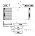
図1は、本発明による連続帳票とその使用方法の実施形態を示す図である。
なお、以下に示す実施形態では、前述した従来例と同様な機能を果たす部分には、同一の符号を付して、重複する図面や説明を適宜省略する。
この実施形態の連続帳票10−1は、厚みの厚い配送伝票(厚手帳票部,重ね合わせ片)10Aと、厚みの薄い商品明細書リスト帳票(薄手帳票部)10Bとが幅方向に連接され、流れ方向に複数ページ連続する(10A−1,10B−1,10A−2,10B−2,・・・)重ね合わせ片付き連続帳票である。
【0024】
この実施形態では、先頭側の1ページ目の配送伝票10A−1のみ切り離されており、先頭側の1ページ目には、薄手の商品明細書リスト帳票10B−1のみを備えている。この商品明細書リスト帳票10Bは、先頭側の1ページ目(P1)と2ページ目(P2)とを重ね合わせてあり、この状態で、箱に収容されている。
【0025】
このように、本実施形態では、商品明細書リスト帳票10Bの先頭側の1ページ目(P1)を2ページ目(P2)側へ折り畳んで、2ページ目(P2)の配送伝票(重ね合せ片を含む部位)10A−2と近似した厚みにして供給するようにしたので、オートロード適性の向上が認められた。
【0026】
以上説明した実施形態に限定されることなく、種々の変形や変更が可能であって、それらも本発明の均等の範囲内である。
(1) 図2(a)に示す連続帳票10−1のように、商品明細書リスト帳票10Bには、先頭側の1ページ目(P1)と2ページ目(P2)とを重ね合わせた状態で、接着又は擬似接着する接着層17を設けるようにしてもよい。このように、接着層17によって、接着又は擬似接着しておけば、セッティング作業がより簡単かつ確実になる。
【0027】
(2) 商品明細書リスト帳票10Bの先頭側の1ページ目(P1)を2ページ目(P2)側へ折り畳んだ例で説明したが、図2(b)に示す連続帳票10−3のように、配送伝票10A−1を切り離さない状態で、商品明細書リスト帳票10Bの先頭側の1ページ目(P1)に配送伝票10A−1との厚み差を調整する上質紙やプリンタ用紙等の別の基材(厚み調整部材)18を接着層17によって貼付するようにしてもよい。
【0028】
(3) 出荷時には、配送伝票10A−1を切り離さない状態で、箱に詰めておき、使用者が、配送伝票10Aの先頭側の1ページ目のみを切り離し(#101)、商品明細書リスト帳票10Bの先頭側の1ページ目(P1)を2ページ目(P2)に重ね合わせて給紙して(#102)、プリンタにセッティングするようにしてもよい。
【0029】
(4) もちろん、出荷時に、図1に示すように、配送伝票10A−1を切り離した状態で、箱に詰めておき、使用者が、商品明細書リスト帳票10Bの先頭側の1ページ目(P1)を2ページ目(P2)に重ね合わせて給紙して(#102)、プリンタにセッティングするようにしてもよい。
【0030】
(5) ピンで送るプリンタの例で説明したが、ピンレスのプリンタにも同様に適用できる。
【0031】
【発明の効果】
以上詳しく説明したように、本発明によれば、幅方向に厚み差のある連続帳票であっても、先頭ページの厚み差をなくす又は少なくしたので、プリンタへのセッティング時に、オートロード適性を大幅に向上させることができる、という効果がある。
【図面の簡単な説明】
【図1】本発明による連続帳票とその使用方法の実施形態を示す図である。
【図2】本発明による連続帳票とその使用方法の他の実施形態を示す図である。
【図3】重ね合せ片付き連続帳票の一般的な構成を示す図である。
【図4】本発明の解決しようとする課題を説明する図である。
【符号の説明】
10 連続帳票
10A 配送伝票
10B 商品明細書リスト帳票
11 基材
12 剥離構造
13 タック紙
14 上紙
15 粘着剤
16 剥離紙[0001]
BACKGROUND OF THE INVENTION
The present invention relates to a continuous business form and its use how thick difference in the width direction by superposition piece or the like.
[0002]
[Prior art]
In recent years, there is a movement in mail order companies or the like to integrate a delivery slip that has been prepared separately and a product statement list form. The reason is
(i) The cost of the medium itself can be reduced,
(ii) Cost reduction and delivery time can be reduced by improving the efficiency of printing work.
(iii) Reduce costs and improve corporate image by eliminating misdelivery.
This is because there are merits.
[0003]
However, if the delivery slip cannot be attached directly to a package such as cardboard, for example, it is necessary to apply a paste on the back side of the printed paper. Since it disappears, tack paper is required on the back side.
On the other hand, since the product specification list form is a simple list, it is sufficient to use high-quality paper or a single printer paper suitable for various printers, and no tack paper is required.
[0004]
A simple method for integrating them is to provide tack paper on the back side of the product specification list form and not use it as tack paper. With this method, it is only necessary to print and process the tack paper, and no special equipment is required for integration.
[0005]
However, in general, the product specification list form is several times larger than the delivery slip, and the tack paper is several times higher than the quality paper or printer paper. It cannot be down, and because it uses a lot of materials, it can lead to deterioration of the corporate image from the viewpoint of environmental protection.
[0006]
For these reasons, continuous forms with overlapping pieces are now in practical use.
FIG. 3 is a diagram showing a general configuration of a continuous form with overlapping pieces.
This
In the
The
On the other hand, the product
[0007]
As shown in FIG. 2, it can be understood that a large thickness difference is generated in the width direction of the
[0008]
The fact that many can not be packed in one box means that a mail order company with a large amount of work has to change the paper to the printer many times, and the workability deteriorates. Conceivable.
However, for example, a printer called a high-speed NIP (non-impact printer) has an automatic paper feeding mechanism called auto-loading, and as long as the paper can be set stably, the physical load on the worker is not necessarily large. There is no.
[0009]
Moreover, as shown in FIG. 4B, if a
[0010]
[Problems to be solved by the invention]
Therefore, the inventor of the present invention has focused on how to overcome the low “autoloadability” that comes from the form of the
[0011]
The autoload suitability to be solved by the present invention will be described below.
Since the auto load mechanism is different for each printer model and for each printer manufacturer, it is difficult to quantify the most desirable sheet physical properties as seen from the printer side.
However, the following physical properties are generally considered important for continuous forms with overlapping pieces.
(A) Difference in thickness in the width direction (b) Curling in the width direction
Of course, it is desirable that the physical properties other than these two points are defined for each printer and conform to the recommended paper standard.
[0013]
Next, as a typical printer, an autoload mechanism of Showa Information Equipment / SX7300 will be described as an example.
(I) First, a form to be printed is placed at a predetermined position on the table according to the vertical size. At this time, the paper width is adjusted by aligning both pin holes with the pin tractor on the table.
(II) When auto loading starts, the tip rises with the lower end of the table as a fulcrum, and the pin hole is fed by the paper feed pin tractor at the top.
(III) When feeding is started through the pin hole, the sheet is nipped by the feed nip roller and automatically fed until the sheet is supplied to the stacker. This completes autoloading.
[0014]
Among these mechanisms, in (I), the “curl in the width direction” in (b) is important, and in (III), the “thickness difference in the width direction” in (a) is important.
If the “curl in the width direction” in (b) is large, the pin hole of the form cannot be aligned with the pin tractor on the table, and paper setting becomes difficult, and the “thickness difference in the width direction” in (a) If it is large, the pressure applied by the nip roller is only on the extremely thick overlapped one side, which makes it easy to meander.
[0015]
Actually, since it is fed by a pin, it often does not mean to meander, but the pin hole is distorted or jammed due to the adjustment state of the printer, the friction level of the members constituting the mechanism such as the nip roller, etc. As a result, there are some cases where autoload failure occurs.
Since this continuous form is a mechanism that feeds through a pin hole, if the paper is successfully set by autoloading, printing in units of one box is possible unless there is a problem. The same applies to curl and thickness difference.
[0016]
An object of the present invention, while taking full advantage of the continuous business form a thick difference in the width direction, to solve these problems, provides excellent continuous business form and their use methods from automatic loading suitability, good Is to build a simple printing job.
[0017]
[Means for Solving the Problems]
In order to solve the above problems, the invention of
[0019]
The invention of
[0021]
According to a third aspect of the present invention, in a method of using a continuous form in which a thick form part and a thin form part having different thicknesses are connected in the width direction and a plurality of pages are continuous in the flow direction, the first page on the top side of the thick form part Is used, and the first page of the thin form section is overlapped with the second page and set in the printer.
[0022]
The invention according to claim 4 is a continuous form in which a thick form part and a thin form part having different thicknesses are connected in the width direction and a plurality of pages are continuous in the flow direction, and the first form on the first side includes the thin form part. In the method of using a continuous form provided only with a copy part, the first page of the thin form part is overlapped with the second page and set in a printer .
[0023]
DETAILED DESCRIPTION OF THE INVENTION
Hereinafter, the present invention will be described in more detail with reference to the drawings.
FIG. 1 is a diagram showing an embodiment of a continuous form and a method of using the same according to the present invention.
In the embodiment described below, the same reference numerals are given to portions that perform the same functions as those of the above-described conventional example, and overlapping drawings and descriptions are omitted as appropriate.
In the continuous form 10-1 of this embodiment, a thick delivery slip (thick form section, overlapping piece) 10A and a thin product specification list form (thin form section) 10B are connected in the width direction, This is a continuous form with overlapping pieces (10A-1, 10B-1, 10A-2, 10B-2,...) Continuous in a plurality of pages in the flow direction.
[0024]
In this embodiment, only the
[0025]
As described above, in this embodiment, the first page (P1) on the top side of the product
[0026]
The present invention is not limited to the embodiment described above, and various modifications and changes are possible, and these are also within the equivalent scope of the present invention.
(1) Like the continuous form 10-1 shown in FIG. 2A, the first page (P1) and the second page (P2) on the top side are superimposed on the product
[0027]
(2) Although the example in which the first page (P1) on the top side of the product
[0028]
(3) At the time of shipment, the
[0029]
(4) Of course, at the time of shipment, as shown in FIG. 1, the
[0030]
(5) Although an example of a printer that sends by pin has been described, the present invention can be similarly applied to a pinless printer.
[0031]
【The invention's effect】
As described above in detail, according to the present invention, even if a continuous form has a thickness difference in the width direction, the thickness difference of the first page is eliminated or reduced. There is an effect that it can be improved.
[Brief description of the drawings]
FIG. 1 is a diagram showing an embodiment of a continuous form and a method of using the same according to the present invention.
FIG. 2 is a diagram showing another embodiment of a continuous form and a method for using the continuous form according to the present invention.
FIG. 3 is a diagram illustrating a general configuration of a continuous form with overlapping pieces.
FIG. 4 is a diagram illustrating a problem to be solved by the present invention.
[Explanation of symbols]
DESCRIPTION OF
Claims (4)
先頭側の1ページ目には、前記薄手帳票部のみ備え、
前記薄手帳票部は、前記先頭側の1ページ目と2ページ目とを折り合わせてあること、
を特徴とする連続帳票。In a continuous form in which a thick form part and a thin form part having different thicknesses are connected in the width direction, and multiple pages are continuous in the flow direction,
The first page of the top side, eh Bei only the thin form part,
The thin form section is formed by folding the first page and the second page on the top side;
A continuous form characterized by
前記薄手帳票部は、前記先頭側の1ページ目と2ページ目とを折り合わせた状態で、接着又は擬似接着してあること、
を特徴とする連続帳票。In the continuous form according to claim 1 ,
The thin form part is bonded or pseudo-bonded in a state where the first page and the second page on the leading side are folded together,
A continuous form characterized by
前記厚手帳票部の先頭側の1ページ目を除去し、前記薄手帳票部の先頭側の1ページ目を2ページ目に重ね合わせて、プリンタにセッティングすること、
を特徴とする連続帳票の使用方法。In a method of using a continuous form in which a thick form part and a thin form part having different thicknesses are connected in the width direction and a plurality of pages are continuous in the flow direction.
Removing the first page on the top side of the thick form section and superimposing the first page on the top side of the thin form section on the second page, and setting the printer;
How to use a continuous form characterized by
前記薄手帳票部の先頭側の1ページ目を2ページ目に重ね合わせて、プリンタにセッティングすること、
を特徴とする連続帳票の使用方法。A thick form part and a thin form part having different thicknesses are connected in the width direction and are continuous forms that are continuous in a plurality of pages in the flow direction. In the method
Superimposing the first page of the thin form part on the second page and setting it on the printer;
How to use a continuous form characterized by
Priority Applications (1)
| Application Number | Priority Date | Filing Date | Title |
|---|---|---|---|
| JP2000193758A JP4253106B2 (en) | 2000-06-28 | 2000-06-28 | Continuous forms and how to use them |
Applications Claiming Priority (1)
| Application Number | Priority Date | Filing Date | Title |
|---|---|---|---|
| JP2000193758A JP4253106B2 (en) | 2000-06-28 | 2000-06-28 | Continuous forms and how to use them |
Publications (3)
| Publication Number | Publication Date |
|---|---|
| JP2002011980A JP2002011980A (en) | 2002-01-15 |
| JP2002011980A5 JP2002011980A5 (en) | 2007-10-18 |
| JP4253106B2 true JP4253106B2 (en) | 2009-04-08 |
Family
ID=18692695
Family Applications (1)
| Application Number | Title | Priority Date | Filing Date |
|---|---|---|---|
| JP2000193758A Expired - Fee Related JP4253106B2 (en) | 2000-06-28 | 2000-06-28 | Continuous forms and how to use them |
Country Status (1)
| Country | Link |
|---|---|
| JP (1) | JP4253106B2 (en) |
Families Citing this family (3)
| Publication number | Priority date | Publication date | Assignee | Title |
|---|---|---|---|---|
| JP4498885B2 (en) * | 2004-10-20 | 2010-07-07 | 大日本印刷株式会社 | Delivery slip with payment slip |
| JP4571524B2 (en) * | 2005-03-09 | 2010-10-27 | 大日本印刷株式会社 | Integrated form |
| JP5709183B2 (en) * | 2013-08-10 | 2015-04-30 | コーホク印刷株式会社 | Bookbinding method of indexed booklet and booklet with index bound by this bookbinding method |
-
2000
- 2000-06-28 JP JP2000193758A patent/JP4253106B2/en not_active Expired - Fee Related
Also Published As
| Publication number | Publication date |
|---|---|
| JP2002011980A (en) | 2002-01-15 |
Similar Documents
| Publication | Publication Date | Title |
|---|---|---|
| JP3690422B2 (en) | Divider capable of printing with integrated laser or inkjet | |
| US20030089083A1 (en) | Custom-decorated giftwrap, kit, and method of and system for custom-decorating the giftwrap | |
| JP4253106B2 (en) | Continuous forms and how to use them | |
| US6601756B2 (en) | Adhesive pattern for a mailer type business form intermediate | |
| JP2006212842A (en) | Thick-page bookbound matter and its bookbinding method | |
| US20060182484A1 (en) | Printing methods, folding methods, and packaging methods for album photo covers | |
| JP5740809B2 (en) | Printing apparatus used for duplex printing method, bookbinding method, duplex printing method | |
| JPH09263073A (en) | Forms with label sheet | |
| JP2010137565A (en) | Duplex printing method, bookbinding method, and printer for use in the duplex printing method | |
| JP2010137564A (en) | Duplex printing method, bookbinding method, and printer for use in the duplex printing method | |
| JP3264764B2 (en) | Bag-shaped sheet | |
| US6705941B1 (en) | Form for non-impact printers | |
| CN104418152A (en) | Film postprocessing device and film post processing method | |
| JP2910017B2 (en) | Envelope making / printing method using electrophotographic apparatus | |
| US20020135176A1 (en) | Method and system for printing and binding folded signatures | |
| JPH0259076B2 (en) | ||
| JP2009051071A (en) | Duplicating form | |
| US6299160B1 (en) | Imposition proofing | |
| US8980393B2 (en) | Printable book binding structure | |
| JP3731869B2 (en) | Single envelope for printer | |
| JP2005324371A (en) | Laminated sheet | |
| JPH0524547Y2 (en) | ||
| JP4424712B2 (en) | Multi-part form | |
| JP2022138363A (en) | Bookbinding apparatus | |
| JP4043980B2 (en) | Multi-layer printing paper |
Legal Events
| Date | Code | Title | Description |
|---|---|---|---|
| RD02 | Notification of acceptance of power of attorney |
Free format text: JAPANESE INTERMEDIATE CODE: A7422 Effective date: 20061115 |
|
| A621 | Written request for application examination |
Free format text: JAPANESE INTERMEDIATE CODE: A621 Effective date: 20070405 |
|
| A521 | Written amendment |
Free format text: JAPANESE INTERMEDIATE CODE: A523 Effective date: 20070904 |
|
| A977 | Report on retrieval |
Free format text: JAPANESE INTERMEDIATE CODE: A971007 Effective date: 20080717 |
|
| A131 | Notification of reasons for refusal |
Free format text: JAPANESE INTERMEDIATE CODE: A131 Effective date: 20080805 |
|
| A521 | Written amendment |
Free format text: JAPANESE INTERMEDIATE CODE: A523 Effective date: 20081003 |
|
| TRDD | Decision of grant or rejection written | ||
| A01 | Written decision to grant a patent or to grant a registration (utility model) |
Free format text: JAPANESE INTERMEDIATE CODE: A01 Effective date: 20090120 |
|
| A01 | Written decision to grant a patent or to grant a registration (utility model) |
Free format text: JAPANESE INTERMEDIATE CODE: A01 |
|
| A61 | First payment of annual fees (during grant procedure) |
Free format text: JAPANESE INTERMEDIATE CODE: A61 Effective date: 20090123 |
|
| R150 | Certificate of patent or registration of utility model |
Free format text: JAPANESE INTERMEDIATE CODE: R150 |
|
| FPAY | Renewal fee payment (event date is renewal date of database) |
Free format text: PAYMENT UNTIL: 20120130 Year of fee payment: 3 |
|
| FPAY | Renewal fee payment (event date is renewal date of database) |
Free format text: PAYMENT UNTIL: 20120130 Year of fee payment: 3 |
|
| FPAY | Renewal fee payment (event date is renewal date of database) |
Free format text: PAYMENT UNTIL: 20130130 Year of fee payment: 4 |
|
| FPAY | Renewal fee payment (event date is renewal date of database) |
Free format text: PAYMENT UNTIL: 20130130 Year of fee payment: 4 |
|
| FPAY | Renewal fee payment (event date is renewal date of database) |
Free format text: PAYMENT UNTIL: 20140130 Year of fee payment: 5 |
|
| LAPS | Cancellation because of no payment of annual fees |