JP4253050B2 - Handle lock - Google Patents
Handle lock Download PDFInfo
- Publication number
- JP4253050B2 JP4253050B2 JP33358897A JP33358897A JP4253050B2 JP 4253050 B2 JP4253050 B2 JP 4253050B2 JP 33358897 A JP33358897 A JP 33358897A JP 33358897 A JP33358897 A JP 33358897A JP 4253050 B2 JP4253050 B2 JP 4253050B2
- Authority
- JP
- Japan
- Prior art keywords
- handle
- door
- lock
- pushing
- latch
- Prior art date
- Legal status (The legal status is an assumption and is not a legal conclusion. Google has not performed a legal analysis and makes no representation as to the accuracy of the status listed.)
- Expired - Fee Related
Links
Images


Description
【0001】
【発明の属する技術分野】
本発明は、ハンドルの開扉方向への押し或いは引き操作によりラッチ錠が解錠され、その儘の動作を続けることで扉が開放されるように構成した所謂プッシュ・プル式のハンドル錠に関するものである。
【0002】
【従来の技術】
上記のハンドル錠は、ラッチ錠を解錠させるハンドル操作に関連させて、扉を開扉させるので、使い勝手が非常に良く、例えば戸建住宅やマンション等の集合住宅の玄関扉、その他、オフィスの入口扉などに広く使用されている。
【0003】
戸建住宅やマンション等の集合住宅では、一部には玄関扉を内開きに設けることもあるが、居住スペースを広くすることを考慮して、玄関扉を外開きに設けることが多く、オフィス等では、スペースに余裕があるので、防犯上の観点や作業の能率化を図る観点から、入口扉を内開きに設けることが多い。
【0004】
ところで、例えば外開き扉用のハンドル錠を内開き扉にも使用しようとすれば、引く側のハンドル即ち室外側のハンドルを室内側に、かつ、押す側のハンドル即ち室内側のハンドルを室外側に取り付ける必要があるが、この場合、防犯上、次のような不都合を生じた。
即ち、ハンドル錠のハンドルを扉内外の扉面に取り付けるための座の取り付けネジは、一般に扉内側の座に露出しており、この扉内側の座を室外側に使用すれば、室外側からは誰でも取り付けネジを外して座を取り外すことができ、誰でも自由に解錠、開扉することができることになる。
【0005】
【発明が解決しようとする課題】
このような理由から、従来は、外開き扉と内開き扉に対して、それぞれに対応した二種類のハンドル錠を製造する必要があった。
従って、製造費は勿論のこと、管理費等を含めた製造原価が極めて高価になった。
【0006】
また、ハンドル錠の取り付け位置が限定される扉の種類あるいは使用者の好み(意匠面や操作性など)に応じて、ハンドルを扉面に縦向きに取り付ける場合と横向きに取り付ける場合とに対処できるするためには、更に二種類の縦向き専用と横向き専用のハンドル錠を必要としたのであり、ここで縦向き専用と横向き専用のハンドル錠とは、錠ケースと錠ケースに内蔵される錠機構部品とによる錠本体とハンドルとを含む広義のもので、互いに錠本体とハンドルとの互換性が全くないことから、製造コストが大幅にアップする上に、部品の管理面などでも多大の問題があった。
【0007】
本発明は、上記従来の欠点を解消するためのもので、一種類のハンドル錠によって、外開き扉や内開き扉の両方に使用できるようにしたものである。
また、ハンドル錠を縦向きハンドル用と横向きハンドル用とに共用できるようにしたものである。
【0008】
【課題を解決するための手段】
本発明にかゝるハンドル錠は、扉の開放端側に設けられるラッチ錠と、扉内外の扉面に縦向きにハンドルを取り付けるための座と、扉内側の座に押し引き両操作可能に保持される内側ハンドルと、扉外側の座に押し引き両操作可能に保持される外側ハンドルと、当該内外両側のハンドルを押し引きの中間位置に保持するバネとを備え、更に、中間位置からの内側ハンドルの押しまたは引き操作あるいは外側ハンドルの押しまたは引き操作の何れを行っても、前記ラッチ錠のラッチボルトの後退を許容させる作動機構を設けて成り、前記作動機構は、前記扉内外両側の座のそれぞれ内部に略中央部がピンにより回動可能に軸支され上下のリンクを連設した作動部材と、前記内外両側のハンドルに各々一体的に設けられた連設部材とを備え、前記連設部材には上下に前記内外両側のハンドルの押しまたは引き操作方向に延びる長孔を形成し、前記作動部材の上下のリンクに突設された係入ピンを前記上下の長孔に係入させてあり、前記内外両側のハンドルの押しまたは引き操作の何れを行っても、扉内外両側の作動部材の何れかの係入ピンが前記上下の長孔の左右の端部の何れかに押され、該係入ピンを介して前記作動部材が時計方向あるいは反時計方向に回動し、前記ラッチボルトの後退を許容させるように構成してある点に特徴がある。
【0009】
【0010】
本発明によるハンドル錠を、外開きタイプの扉に取り付けた場合は、中間位置に保持された外側ハンドルの引き操作ならびに内側ハンドルの押し操作によって、或いは、ハンドル錠を内開きタイプの扉に取り付けた場合は、中間位置に保持された内側ハンドルの引き操作ならびに外側ハンドルの押し操作によって、ラッチ錠のラッチボルトが後退あるいは後退が許容されるもので、後は、その儘の動作を続けることで扉が開放されることになる。
【0011】
従って、ハンドルの組み立て並びに分解用の止めネジ関係を扉内側に配置すれば、作動機構を含むハンドル一式についての入れ換えを一切せずに、従来と同様に錠本体は単にラッチボルトの取り付け向きだけを変更するだけで、構成部材を共通にして、防犯上の不都合が生じることなく、一種類のハンドル錠で内開き扉にも外開き扉にも使用することができる。
【0012】
【0013】
要約すれば、本発明では、防犯上の不都合を生じることのないハンドル錠を、構成部材を共通にして、外開き扉と内開き扉とに兼用構成でき、従って、一種類のハンドル錠で外開きタイプと内開きタイプの二種類の扉用として、構成部材を共通にして使用できることから、ハンドル錠の製造コストを大幅にダウンできる上に、部品の管理面ならびに保管スペース面での改善も達成される。
【0014】
【発明の実施の形態】
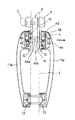
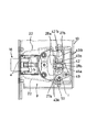
以下、本発明によるハンドル錠の実施の形態を図面に基づいて説明する。図1はハンドル錠のハンドルを扉面に縦向きに取り付けた外開き扉の概略正面図、図2は扉の開放端側から見たハンドル錠の側面図、図3は錠ケースの一部を破断して示すハンドル錠の正面図、図4は縦向きハンドルの縦断側面図、図5はラッチボルトの斜視図、図6はラッチ錠の一部を破断したハンドル錠の平面図を示している。
【0015】
図7は外開き扉の内側ハンドルの押し操作状態を示す断面図、図8は外開き扉の外側ハンドルの引き操作状態を示す断面図、図9はラッチボルトに対するロッキングピースの離脱状態を示す説明図、図10は内開き扉の内側ハンドルの引き操作状態を示す断面図、図11は内開き扉の外側ハンドルの押し操作状態を示す断面図である。
【0016】
図12はハンドル錠のハンドルを横向きに取り付けた外開き扉の部分正面図、図13は横向きハンドル用としたハンドル錠の一部を破断した正面図、図14は横向きハンドル用としたハンドル錠のラッチボルに対するロッキングピースの離脱状態を示す説明図、図15は作動機構の作動部材を正逆方向に回動させるように構成した縦向きハンドルの縦断側面図、図16は縦向きハンドル用としたハンドル錠の一部の破断正面図、図17は横向きハンドル用としたハンドル錠の一部の破断正面図を示している。
【0017】
図1〜図4において、図中の1はヒンジ2,2を介して扉枠3に蝶着された例えば外開きの扉、4は扉1の開放端側に設けられたハンドル錠で、シリンダ5のキー孔6に差し込まれる扉外側でのキー操作または扉内側でのサムターン7の操作によって施解錠される本締まり錠(デッドボルト8のみを示している。)と、ラッチ錠9とを、錠ケース10に内蔵している。
【0018】
11a,11bは錠ケース10を挟んで扉内外の扉面に取り付けられたハンドルで、この実施の形態では、上下の座12,13を介してハンドル11a,11bを縦向きにして取り付けているが、図12に示して後述するように、ハンドル11a,11bを座12,13を介して扉面に横向きに取り付けることも選択できる。
【0019】
この一対のハンドル11a,11bは、それぞれ下部側の座13,13に押し引き可能に保持され、かつ、各ハンドル11a,11bは、詳細を後述するように、バネ14,14によって押し引きの中間位置に保持されるように構成されている。
15,15は中間位置に保持された内側ハンドル11aの押し操作ならびに外側ハンドル11bの引き操作によって、前記ラッチ錠9のラッチボルト16の後退を許容させる作動機構である。
【0020】
以下、具体構造について説明すると、上記のラッチ錠9は、特に限定されるものではないが、この実施の形態では、いわゆる反転ラッチ式に構成しており、図5に示すように、先端の扉閉じ方向の面を傾斜面16aとし、他方の面を扉枠3側のストライキ17の受孔18に係合する係合面16bとした平面形状がほゞ菱形のラッチボルト16の後部側に、バネ受け面16cを傾斜させた凹部16dを形成すると共に、ラッチボルト16の上下の膨出部16e,16eに、前後方向の係止溝a,aを幅方向の略中央部に形成し、このラッチボルト16とラッチバネ19とを、錠ケース10のフロントプレート20を取り外した状態で、ラッチバネ19とラッチボルト16の順に、錠ケース10内のラッチケース21に嵌入し、かつ、錠ケース10にフロントプレート20を取り付けている。
【0021】
そして、それぞれ先端の係止片b,bがラッチボルト16の係止溝a,aに係止してラッチボルト16の反転を阻止する上下一対のロッキングピース22,22を、ピン23を介して錠ケース10に枢着すると共に、各ロッキングピース22の係止片b,bを係止溝a,aに付勢係止させるツル巻きバネ24,24を設け、かつ、ロッキングピース22,22のそれぞれに、ラッチボルト16の後部側で重なり合う部材25,25を連設して、この連設部材25,25を、それの重なり合い部に形成の長孔cに挿通される連結ピン26によって連結し、前記ロッキングピース22,22の一方の係止片bを係止溝aから離脱させた際に、これに連動してロッキングピース22,22の他方の係止片bも係止溝aから離脱させるようにしている。
【0022】
更に、一方のロッキングピース22に、このロッキングピース22を回動させて、これの係止片bをラッチボルト16の係止溝aから離脱させる縦向きハンドル用の操作部材27を連設すると共に、連結ピン26による一対のロッキングピース22,22の連結部には、この連結部をラッチボルト16の後部側に押圧して、一対のロッキングピース22,22の係止片b,bをラッチボルト16の係止溝a,aから離脱させる横向きハンドル用の操作部材28を設けている。
【0023】
従って、前記ラッチ錠9のラッチボルト16は、常時はラッチバネ19の付勢力によってフロントプレート20の出入口20aから突出しており、閉扉時には、閉扉動作に伴う扉枠3側のストライキ17の端面17aと傾斜面16aとの作用でラッチボルト16が一旦摺動後退し、その後、ラッチボルト16が扉枠3側のストライキ17の受孔18に突入して係合するもので、このラッチボルト16の係止溝a,aには、ロッキングピース22,22の係止片b,bが係止して、ラッチボルト16の反転が阻止されていることから、扉3は風圧等で開かない施錠状態となる(図3及び図6を参照)。
【0024】
上部側(錠ケース10側)のハンドル取り付け座12,12は、扉面に接する受け部材29と、この受け部材29を扉面に押し付ける押圧部材30とから成り、かつ、内側ハンドル11aの押圧部材30に、取り付けネジ31の挿通孔dを形成した押圧板32を設ける一方、外側ハンドル11bの押圧部材30には、扉1をほゞ貫通する取り付けネジ螺着用の雌ネジを設けた取付柱33を設けて、この取付柱33の雌ネジに扉1内側から取り付けネジ31を螺着することで、上部側のハンドル取り付け座12,12を、扉1内外の扉面に取り付けるようにしている。
【0025】
下部側(錠ケース10とは反対側)の内側ハンドル11a用の取り付け座13は、扉面に接する受け部材34を備えており、この受け部材34に取り付けネジ35の挿通孔eを形成する一方、外側ハンドル11b用の取り付け座13には、扉1をほゞ貫通するネジ螺着用の雌ネジを設けた取付柱36を設けて、この取付柱36の雌ネジに扉1の内側から取り付けネジ35を螺着することで、下部側のハンドル取り付け座13,13を、扉1内外の扉面に取り付けるようにしている。
【0026】
ハンドル11a,11bのそれぞれは、例えば中空の金属製(中空でなくともよく、また、合成樹脂製であってもよい。)であって、握り部の上下の空間部に断面コの字状の保持部材37,38を固着し、かつ、下部側の保持部材38,38にフックf,fを切り起こして、このフックf,fを下部側の座13,13に係止連結し、この係止連結部にハンドル11a,11bを枢支し、ハンドル11a,11bの押し引きを可能にしているのである。
【0027】
尚、下部側のハンドル取り付け座13,13のそれぞれには、フックfを係止保持させるためのバネ部材39,39を設けている。
また、内側ハンドル11aを上下のハンドル取り付け座12,13に保持させた状態で、この内側ハンドル11aを座12,13に固定するために、止めネジ40,40を設けている(図2を参照)。
【0028】
作動機構15,15は、次のように構成されている。即ち、錠ケース10とこれの蓋体41とに、それぞれT字状の開口部(蓋体41側の開口部を図3に仮想線で示している。)42,42を形成すると共に、前記一方のロッキングピース22に連設の操作部材27に下部側から係止する連動部材43を、開口部42,42を迂回させるようにして、前記錠ケース10に上下にスライド可能に設ける一方、上部側のハンドル座12,12の内部には、それぞれ開口部42,42の上下方向に延びる縦部分42a,42aを通して遊端側を錠ケース10内に挿入させるように、内側ハンドル用と外側ハンドル用の作動部材45a,45bを、ピン44を支点に回動可能に枢着し、この作動部材45a,45bのそれぞれに、上向きと下向きにリンク46,46を連設している。
【0029】
そして、各ハンドル11a,11bの上部側の保持部材37,37に、コの字状の連設部材47,47を連設して、この連設部材47,47に、ハンドル押し引き方向の長孔h,hを形成する一方、前記リンク46,46の遊端側には、長孔h,hに係入するピン48,48を設け、かつ、このピン48,48を長孔h,hの互いに異なる方向の孔端部に係止させる機能と、図4に示される如くハンドル11a,11bを押し引きの中間位置に保持させる機能とを発揮させるように、前記バネ14,14を作動部材45a,45bの枢着ピン44,44に保持させているのである。
【0030】
上記の構成によれば、ラッチ錠9による扉1の施錠状態(図3及び図6を参照)において、図7に示すように、外開き扉1を開扉するように、図4に示す中間位置に保持されている内側ハンドル11aを押し操作すると、連設部材47の下部側長孔hの左端に係止しているピン48が押されて、このピン48とリンク46とを介して作動部材45aが枢着ピン44を支点に上方に回動する。
【0031】
或いは図8に示すように、中間位置に保持されている外側ハンドル11bを引き操作した場合は、連設部材47の上部側長孔hの左端に係止しているピン48が引かれて、このピン48とリンク46とを介して作動部材45bが枢着ピン44を支点に上方に回動するのであり、この回動に伴って、図9に示すように、連動部材43が上方にスライドし、一方のロッキングピース22に連設の操作部材27が、上記連動部材43の作動部43aによって押動され、このロッキングピース22が反時計方向に回動し、かつ、連結ピン26による連設部材25,25どうしの連結部を介して、他方のロッキングピース22も時計方向に回動することで、これら一対のロッキングピース22,22の係止片b,bがラッチボルト16の係止溝a,aから離脱するのであって、ラッチボルト16の反転が可能になるのである。
【0032】
従って、この儘の開扉動作を続けると、図6の仮想線の如く、ラッチボルト16が反転して、それまではストライキ17の受孔18に係合していた係合面16bが傾斜姿勢に切り換えられ、この傾斜係合面16bとストライキ17の受孔18との作用でラッチボルト16が一旦摺動後退し、開扉される。開扉後、ラッチボルト16は、ラッチバネ19の付勢力によってフロントプレート20の出入口20aから突出し、図6の実線状態に示される元の姿勢に復帰するのである。
【0033】
上記構成のハンドル錠4は外開き扉用であるが、フロントプレート20を取り外して、ラッチ錠9のラッチボルト16をラッチケース21から抜き出し、このラッチボルト16のストライキ17に対する係合向きを反転させて、ラッチケース21に戻し、かつ、フロントプレート20を錠ケース10に取り付けることで、ハンドル錠4を内開き扉用のものに組み替えることができる。
【0034】
このように組み替えたハンドル錠4を、内開き扉1の開放端側に設けて、図10に示すように、内開き扉1を開扉するように、図4の中間位置に保持されている内側ハンドル11aを引き操作すると、連設部材47の上部側長孔hの右端に係止しているピン48が引かれて、このピン48とリンク46とを介して作動部材45aが枢着ピン44を支点に上方に回動する。
【0035】
或いは図11に示すように、図4の中間位置に保持されている外側ハンドル11bを押し操作すると、連設部材47の下部側長孔hの右端に係止しているピン48が押されて、このピン48とリンク46とを介して作動部材45bが枢着ピン44を支点に上方に回動することから、後は、図9に示して前記したと同様にラッチボルト16は反転が可能となるもので、この儘の開扉動作を続けることによって、内開き扉1を開扉させることができるのである。
【0036】
即ち、ハンドル11a,11bの組み立て並びに分解用の取り付けネジ31,35,40の関係を扉内側に配置したままで、作動機構15,15を含むハンドル一式についての入れ換えは一切せずに、単にラッチボルト16の取り付け向きを変更するだけで、構成部材を共通にして、防犯上の問題を一切伴うことのないハンドル錠4を、外開きタイプと内開きタイプとに兼用できるものを提供することができるのである。
【0037】
更に、図示したように、前記作動部材45a,45bの遊端側を錠ケース10内に突入させるための開口部42,42として、これをT字状に形成して、横向きハンドル用の操作部材28を、開口部42,42の左右方向に延びる横部分42b,42b(図3参照)に相対峙させるように配置しているので、図12及び図13に示すように、作動機構15,15の作動部材45a,45bを開口部42,42の横部分42b,42bに挿通させるようにして、ハンドル取り付け座12,13と作動機構15とを含むハンドル一式を、扉内外の扉面に横向きに取り付けることで、上記した外開きタイプと内開きタイプに兼用できるハンドル錠4を、それぞれ縦向きハンドル用と横向きハンドル用のハンドル錠にも兼用することができる。
【0038】
このように構成したハンドル錠4においては、扉内外のいずれのハンドル11a,11bにおいても、これを中間位置から押し操作または引き操作することによって、作動機構15,15の作動部材45a,45bがそれぞれ同方向に回動して、横向きハンドル用の操作部材28を押圧することで、図14に示すように、一対のロッキングピース22,22の係止片b,bがラッチボルト16の係止溝a,aから離脱して、ラッチボルト16の反転が可能になるのであって、この儘ハンドル11a,11bの押しあるいは引き動作を続けることによって扉1を開扉させることができるのである。
【0039】
尚、錠ケース10とこれの蓋体41とに設けた開口部42,42として、これをT字状に形成することは必須の用件ではなく、作動部材45a,45bを縦向き又は横向きに取り付けた状態で、一対のロッキングピース22,22の係止片b,bをラッチボルト16の係止溝a,aから離脱させるように、作動部材45a,45bが回動できるようにするならば、開口部42,42を井桁状や角形などに形成してもよいのである。
【0040】
また、上記の実施の形態では、ハンドル側の連設部材47に長孔h,hを形成し、この長孔h,hに係止するピン48,48を、作動部材45a,45bに連設のリンク46,46に設けているが、作動部材45a,45bに連設のリンク46,46にハンドル押し引き方向の長孔h,hを形成し、この長孔h,hに係止するピン48,48をハンドル側の連設部材47に設けるようにしてもよいのである。
【0041】
ここで、図15〜図17に示すように、ハンドル錠4として、例えば井桁状の開口部42’,42’を上下方向と左右方向で挟むように、それぞれ二組の縦向きハンドル用の操作部材27a,27bと、横向きハンドル用の操作部材28a,28bとを、ラッチ錠9に備えさせる一方、作動機構15,15の作動部材45a,45bを、中間位置からのハンドル11a,11bの押し操作ならびに引き操作によって、正逆方向に回動させるように構成しても、単にラッチボルト16の取り付け向きを変更するだけで、外開きタイプと内開きタイプの扉に兼用できるハンドル錠4を、それぞれ縦向きハンドル用と横向きハンドル用のハンドル錠にも構成することができる。
【0042】
即ち、図16に示すように、ロッキングピース22,22のそれぞれに、縦向きハンドル用の操作部材27a,27bを連設すると共に、下部側の操作部材27aを上方に且つ上部側の操作部材27bを下方に回動させる連動部材43A,43Bを、錠ケース10にスライド可能に設け、かつ、一方の横向きハンドル用の操作部材28aを上部側の操作部材27bに連設すると共に、他方の横向きハンドル用の操作部材28bをピン49によって錠ケース10に枢着し、この操作部材28bと縦向きハンドル用の下部側の操作部材27aとを、長孔iとピン50とを介して連結するのである。
【0043】
そして、作動機構15,15として、図15では縦向きハンドル11a,11bを対象にしているので、扉面に沿わせるようにリンク51を延設した作動部材45a,45bを、開口部42’,42’の上下方向に延びる縦部分42’a,42’aを通して、縦向きハンドル用の操作部材27a,27b間に配置するように、ラッチ錠9側のハンドル取り付け座12,12のそれぞれに、ピン44を支点に回動可能に枢着すると共に、前記リンク51の遊端側とハンドル側の連設部材47とをピン52によって連結し、かつ、ハンドル11a,11bを押し引きの中間位置に保持させるためのバネ14,14を、例えばハンドル取り付け座12,12の押圧部材30,30と作動部材45a,45bとにわたって設けるのである。
【0044】
ハンドル11a,11bを横向きに取り付ける場合は、図17に示すように、前記作動機構15,15の作動部材45a,45bを、開口部42’,42’の左右方向に延びる横部分42’b,42’bを通して、横向きハンドル用の操作部材28a,28b間に配置するのである。
【0045】
上記の構成において、図15及び図16に示すように、中間位置からのハンドル11a,11bの押し操作によって、いずれも作動部材45a,45bが下方に回動して、連動部材43Aを介して上部側の操作部材27bが下方に回動し、中間位置からのハンドル11a,11bの引き操作では、いずれも作動部材45a,45bが上方に回動して、連動部材43Bを介して下部側の操作部材27aが上方に回動する。
【0046】
ハンドル11a,11bを扉内外の扉面に横向きに取り付けた場合は、図17に示すように、中間位置からのハンドル11a,11bの押し操作によって、いずれも作動部材45a,45bが操作部材28aを押圧することで、上部側の操作部材27bが下方に回動し、中間位置からのハンドル11a,11bの引き操作では、いずれも作動部材45a,45bが操作部材28bを回動させて、下部側の操作部材27aを上方に回動させるもので、いずれの操作によっても、一対のロッキングピース22,22の係止片b,bがラッチボルト16の係止溝a,aから離脱することで、扉1を開扉させることができるのである。
【0047】
しかし、このように構成した場合は、一対のロッキングピース22,22の係止片b,bをラッチボルト16の係止溝a,aから離脱させるための手段(それぞれ二組の縦向きハンドル用と横向きハンドル用の操作部材27a,27b、28a,28bと、連動部材43A,43B)が、構成的にやゝ複雑になる。
【0048】
これに対して、図3および図4に示した構造であれば、図7〜図11に基づいて説明したように、ハンドル11a,11bの押し操作あるいは引き操作のいずれによっても、作動部材45a,45bが同方向に回動されるので、係止溝a,aからの係止片b,bの離脱手段(操作部材27,28と連動部材43)を非常に簡素化でき、ラッチ錠9の構成が簡単になることで、大幅なコストダウンが達成される効果がある。
【0049】
尚、外開きタイプと内開きタイプとに兼用できるハンドル錠4として、これを縦向きハンドル専用に構成するときは、横向きハンドル用の操作部材28は不要であり、横向きハンドル専用に構成するときは、縦向きハンドル用の操作部材27及び連動部材43は不要であって、ラッチ錠9の更なる簡素化とコストダウンとが達成されることは言うまでもない。
【0050】
また、実施の形態によるハンドル錠4では、デッドボルト8とシリンダ5とサムターン7等から成る本締まり錠を備えさせているが、本締まり錠を有さずラッチ錠9のみを備えるハンドル錠4を、本発明の適用対象にすることもできる。
【0051】
更に、ラッチ錠9として、いわゆる反転ラッチ式のものについて説明したが、反転しない構造で且つ作動部材45a,45bの回動に伴って、ラッチボルト16を直接的に後退させる構造のものを用いこともできるのである。
【0052】
【発明の効果】
以上説明したように、請求項1記載のハンドル錠によれば、単にラッチボルトの取り付け向きだけを変更するだけで、防犯上の問題を一切伴うことのないハンドル錠を、構成部材を共通にして、外開き扉と内開き扉との両方にそのまま使用できるものを提供することができる。
【0053】
【0054】
従って、外開きタイプと内開きタイプの二種類のハンドル錠を、構成部材を共通にして構成できることから、ハンドル錠の製造コストを大幅にダウンできることは勿論、部品の管理面ならびに保管スペース面での改善も達成されるようになったのである。
【図面の簡単な説明】
【図1】 ハンドル錠のハンドルを縦向きに取り付けた外開き扉の正面図である。
【図2】 扉の開放端側から見たハンドル錠の側面図である。
【図3】 錠ケースの一部を破断して示すハンドル錠の正面図である。
【図4】 縦向きハンドルの縦断側面図である。
【図5】 ラッチボルトの斜視図である。
【図6】 ラッチ錠の一部を破断したハンドル錠の平面図である。
【図7】 外開き扉の内側ハンドルの押し操作状態を示す断面図である。
【図8】 外開き扉の外側ハンドルの引き操作状態を示す断面図である。
【図9】 ラッチボルに対するロッキングピースの離脱状態を示す説明図である。
【図10】 内開き扉の内側ハンドルの引き操作状態を示す断面図である。
【図11】 内開き扉の外側ハンドルの押し操作状態を示す断面図である。
【図12】 ハンドル錠のハンドルを横向きに取り付けた外開き扉の部分正面図である。
【図13】 横向きハンドル用としたハンドル錠の一部を破断した正面図である。
【図14】 横向きハンドル用としたハンドル錠のラッチボルに対するロッキングピースの離脱状態を示す説明図である。
【図15】 作動機構の作動部材を正逆方向に回動させるように構成した縦向きハンドルの縦断側面図である。
【図16】 縦向きハンドル用としたハンドル錠の一部の破断正面図である。
【図17】 横向きハンドル用としたハンドル錠の一部の破断正面図である。
【符号の説明】
1…扉、9…ラッチ錠、11a,11b…ハンドル、12,13…ハンドル取り付け座、14…ハンドルの中間位置保持バネ、15…作動機構、16…ラッチボルト、27…縦向きハンドル用の操作部材、28…横向きハンドル用の操作部材。[0001]
BACKGROUND OF THE INVENTION
The present invention relates to a so-called push-pull type handle lock configured such that the latch lock is unlocked by pushing or pulling the handle toward the door opening direction, and the door is opened by continuing the operation of the hook. It is.
[0002]
[Prior art]
The above handle lock is very convenient because it opens the door in relation to the handle operation that unlocks the latch lock, for example, entrance doors of apartment houses such as detached houses and condominiums, etc. Widely used for entrance doors.
[0003]
In apartment houses such as detached houses and condominiums, some entrance doors may be provided inside the door, but in order to increase the living space, entrance doors are often provided outside the office. For example, since there is room in the space, the entrance door is often provided on the inside opening from the viewpoint of crime prevention and efficiency of work.
[0004]
By the way, for example, if the handle lock for the outer opening door is used for the inner opening door, the pulling side handle, that is, the outdoor side handle is set to the indoor side, and the pushing side handle, that is, the indoor side handle is set to the outdoor side. However, in this case, the following inconvenience occurred for crime prevention.
That is, the seat mounting screw for attaching the handle of the handle lock to the door surface inside and outside the door is generally exposed on the seat inside the door, and if this seat inside the door is used on the outdoor side, Anyone remove the mounting screw do it The seat can be removed, and anyone can freely unlock and open the door.
[0005]
[Problems to be solved by the invention]
For these reasons, conventionally, it has been necessary to manufacture two types of handle locks corresponding to each of the outer opening door and the inner opening door.
Therefore, the manufacturing cost including the management cost as well as the manufacturing cost has become extremely expensive.
[0006]
In addition, depending on the type of door or the user's preference (design surface, operability, etc.) where the handle lock is attached, the handle can be mounted vertically or horizontally on the door surface. In order to do this, two types of vertical and horizontal handle locks were required. Here, the vertical and horizontal handle locks are a lock mechanism and a lock mechanism built into the lock case. It is a broad definition that includes a lock body and a handle depending on the parts, and since there is no compatibility between the lock body and the handle, the manufacturing cost is greatly increased. there were.
[0007]
The present invention is for overcoming the above-described conventional drawbacks, and can be used for both an outer opening door and an inner opening door with one kind of handle lock.
Further, the handle lock can be shared for the vertical handle and the horizontal handle.
[0008]
[Means for Solving the Problems]
The present invention The handle lock on the door is a latch lock provided on the open end of the door and the door surface inside and outside the door. Vertically A seat for attaching the handle, an inner handle that can be pushed and pulled on the seat inside the door, an outer handle that can be pushed and pulled on the seat on the outside of the door, Both inside and outside And a spring for holding the handle of the inner handle in the middle position of the push-pull, and further, pushing the inner handle from the middle position. Or Pull operation Or Push the outer handle Or Regardless of the pulling operation, the latch bolt of the latch lock After Provide an operating mechanism that allows retraction. The actuating mechanism is integrated with an actuating member having a substantially central portion pivotally supported by a pin inside the seats on both the inner and outer sides of the door, and an upper and lower link and a handle on both the inner and outer sides. A continuous hole formed in the upper and lower sides of the handle and extending in the direction of pushing or pulling the handle on both the inner and outer sides and projecting from the upper and lower links of the operating member. Engaging pins are engaged in the upper and lower elongated holes, and any of the operating members on both the inner and outer sides of the door is engaged or disengaged regardless of whether the handle on both the inner and outer sides is pushed or pulled. The operating member is pushed by one of the left and right ends of the long hole, and the actuating member is rotated clockwise or counterclockwise via the engaging pin to allow the latch bolt to retract. There is a feature in the point.
[0009]
[0010]
The present invention By handle lock, Outside When attached to an open-type door, it was held at an intermediate position. Outside Pulling the side handle and Inside By pushing the side handle or by locking the handle Inside When attached to an open-type door, it was held at an intermediate position. Inside Pulling the side handle and Outside By pushing the side handle, the latch bolt of the latch lock is allowed to move backward or backward, and thereafter, the door is opened by continuing the operation of the hook.
[0011]
Therefore, set screws for assembling and disassembling the handle are placed inside the door. if, Without changing the handle set including the operating mechanism at all, the lock body simply changes the mounting direction of the latch bolt as in the past, and the components are made common. , Prevention It can be used for both the inner and outer doors with a single handle lock without any inconvenience.
[0012]
[0013]
In summary, The present invention Then, the handle lock that does not cause inconvenience in crime prevention, Outside With hinged door Inside Can be configured as a double door , Obedience With one kind of handle lock Outside Open type and Inside Two types of opening type For doors and In addition, since the components can be used in common, the manufacturing cost of the handle lock can be greatly reduced, and improvements in parts management and storage space can be achieved.
[0014]
DETAILED DESCRIPTION OF THE INVENTION
Embodiments of a handle lock according to the present invention will be described below with reference to the drawings. Fig. 1 is a schematic front view of an open door with the handle of the handle lock vertically attached to the door surface, Fig. 2 is a side view of the handle lock as viewed from the open end of the door, and Fig. 3 is a part of the lock case. 4 is a front view of the handle lock shown broken, FIG. 4 is a longitudinal side view of the vertical handle, FIG. 5 is a perspective view of the latch bolt, and FIG. 6 is a plan view of the handle lock with a part of the latch lock broken. .
[0015]
7 is a cross-sectional view showing a pushing operation state of the inner handle of the outer opening door, FIG. 8 is a cross-sectional view showing a pulling operation state of the outer handle of the outer opening door, and FIG. 9 is an explanation showing a releasing state of the locking piece with respect to the latch bolt. FIG. 10 is a sectional view showing a pulling operation state of the inner handle of the inner opening door, and FIG. 11 is a sectional view showing a pushing operation state of the outer handle of the inner opening door.
[0016]
FIG. 12 is a partial front view of the outer opening door in which the handle of the handle lock is attached sideways, FIG. 13 is a front view of a part of the handle lock for the side handle, and FIG. 14 is a view of the handle lock for the side handle. FIG. 15 is a longitudinal side view of a vertical handle configured to rotate the operating member of the operating mechanism in the forward and reverse directions, and FIG. 16 is a handle for the vertical handle. FIG. 17 is a partially cutaway front view of a handle lock for a lateral handle.
[0017]
In FIG. 1 to FIG. 4,
[0018]
[0019]
The pair of
[0020]
Hereinafter, the specific structure will be described. The
[0021]
Then, a pair of upper and
[0022]
Further, an
[0023]
Accordingly, the
[0024]
The
[0025]
A mounting
[0026]
Each of the
[0027]
Each of the lower
In addition, set
[0028]
The
[0029]
Then, the
[0030]
According to said structure, in the locked state (refer FIG.3 and FIG.6) of the
[0031]
Alternatively, as shown in FIG. 8, when the
[0032]
Therefore, if the door opening operation is continued, the
[0033]
The
[0034]
The
[0035]
Or as shown in FIG. Of FIG. When the
[0036]
In other words, the relationship between the assembly screws 31, 35, 40 for assembling and disassembling the
[0037]
Further, as shown in the drawing, the free ends of the
[0038]
In the
[0039]
In addition, it is not an essential requirement to form the opening
[0040]
In the above embodiment, the long holes h, h are formed in the connecting
[0041]
Here, as shown in FIGS. 15 to 17, as the
[0042]
That is, as shown in FIG. 16, the operating
[0043]
As the
[0044]
When the
[0045]
In the above-described configuration, as shown in FIGS. 15 and 16, the operating
[0046]
When the
[0047]
However, when configured in this way, means for separating the locking pieces b, b of the pair of locking
[0048]
On the other hand, in the structure shown in FIGS. 3 and 4, as described with reference to FIGS. 7 to 11, the operating
[0049]
still, Outside Open type and Inside When the
[0050]
Further, the
[0051]
Furthermore, as the
[0052]
【The invention's effect】
As described above, according to the handle lock of the first aspect, the handle lock having no security problem can be obtained by simply changing the mounting direction of the latch bolt, and using the same component. , Outside With hinged door Inside What can be used as it is for both the hinged door can be provided.
[0053]
[0054]
Therefore, Outside Open type and Inside Two types of hands Le tablets Since the components can be configured in common, not only can the manufacturing cost of the handle lock be greatly reduced, but also improvements in terms of parts management and storage space can be achieved.
[Brief description of the drawings]
FIG. 1 is a front view of an external door with a handle lock handle attached vertically.
FIG. 2 is a side view of the handle lock viewed from the open end side of the door.
FIG. 3 is a front view of the handle lock shown by cutting a part of the lock case.
FIG. 4 is a vertical side view of a vertical handle.
FIG. 5 is a perspective view of a latch bolt.
FIG. 6 is a plan view of the handle lock in which a part of the latch lock is broken.
FIG. 7 is a cross-sectional view showing a pushing operation state of an inner handle of the outer door.
FIG. 8 is a cross-sectional view showing a pulling operation state of the outer handle of the outer door.
FIG. 9 is an explanatory view showing a state in which the locking piece is detached from the latch bolt.
FIG. 10 is a cross-sectional view showing a pulling operation state of an inner handle of the inner opening door.
FIG. 11 is a cross-sectional view showing a pressing operation state of the outer handle of the inner opening door.
FIG. 12 is a partial front view of an outer opening door in which a handle of a handle lock is attached sideways.
FIG. 13 is a front view in which a part of a handle lock for a lateral handle is broken.
FIG. 14 is an explanatory view showing a disengagement state of the locking piece with respect to the latch bolt of the handle lock for the lateral handle.
FIG. 15 is a vertical side view of a vertical handle configured to rotate an operating member of an operating mechanism in a forward and reverse direction.
FIG. 16 is a partially cutaway front view of a handle lock for a vertically oriented handle.
FIG. 17 is a partially cutaway front view of a handle lock for a lateral handle.
[Explanation of symbols]
DESCRIPTION OF
Claims (1)
Priority Applications (1)
| Application Number | Priority Date | Filing Date | Title |
|---|---|---|---|
| JP33358897A JP4253050B2 (en) | 1997-11-17 | 1997-11-17 | Handle lock |
Applications Claiming Priority (1)
| Application Number | Priority Date | Filing Date | Title |
|---|---|---|---|
| JP33358897A JP4253050B2 (en) | 1997-11-17 | 1997-11-17 | Handle lock |
Publications (2)
| Publication Number | Publication Date |
|---|---|
| JPH11148259A JPH11148259A (en) | 1999-06-02 |
| JP4253050B2 true JP4253050B2 (en) | 2009-04-08 |
Family
ID=18267730
Family Applications (1)
| Application Number | Title | Priority Date | Filing Date |
|---|---|---|---|
| JP33358897A Expired - Fee Related JP4253050B2 (en) | 1997-11-17 | 1997-11-17 | Handle lock |
Country Status (1)
| Country | Link |
|---|---|
| JP (1) | JP4253050B2 (en) |
Families Citing this family (6)
| Publication number | Priority date | Publication date | Assignee | Title |
|---|---|---|---|---|
| KR100414361B1 (en) * | 2000-09-28 | 2004-01-13 | 윤영순 | Door Lock System |
| JP2007291688A (en) * | 2006-04-24 | 2007-11-08 | Sankyo Tateyama Aluminium Inc | Door device with temporary lock function for buildings |
| JP5150134B2 (en) * | 2007-05-10 | 2013-02-20 | 美和ロック株式会社 | Latch lock for free door |
| JP2009030398A (en) * | 2007-07-30 | 2009-02-12 | Alpha Corp | Latch device |
| JP5663316B2 (en) * | 2011-01-12 | 2015-02-04 | 美和ロック株式会社 | Handle device for latch lock |
| JP7244933B2 (en) * | 2020-09-28 | 2023-03-23 | 株式会社ゴール | reversing latch lock |
-
1997
- 1997-11-17 JP JP33358897A patent/JP4253050B2/en not_active Expired - Fee Related
Also Published As
| Publication number | Publication date |
|---|---|
| JPH11148259A (en) | 1999-06-02 |
Similar Documents
| Publication | Publication Date | Title |
|---|---|---|
| US4735447A (en) | Three-part vehicle-door latch | |
| US7080861B2 (en) | Anti-panic mechanism of vehicle door latch device | |
| US7836738B2 (en) | Mortise lock for ordinary door and panic door | |
| US7377140B2 (en) | Lock with clutching function | |
| US8201857B2 (en) | Adjustable driving mechanism for panic exit door lock | |
| US8267441B2 (en) | Operating device for lock | |
| GB2162573A (en) | Door handle device | |
| US6993946B1 (en) | Lock with clutching function | |
| US5791174A (en) | Paddle handle locks | |
| JP4253050B2 (en) | Handle lock | |
| US6164099A (en) | Door lock | |
| US20060162404A1 (en) | Luggage locking device with an indicating unit | |
| US6101852A (en) | Padlock with removable shackle | |
| EP2186715B1 (en) | Anti-theft device for closing and locking a case on a rack of a motorcycle | |
| JP3993913B2 (en) | Push-pull tablet | |
| US20090229322A1 (en) | Storm door lock assembly | |
| JP4566225B2 (en) | Door lock | |
| JP4165790B2 (en) | Latch lock for door | |
| JP4235443B2 (en) | Push-pull locking device | |
| US9145712B1 (en) | Lock cylinder for a door lock | |
| JPS6140860Y2 (en) | ||
| JP3978600B2 (en) | Unlocking mechanism with lever handle | |
| JP2004137841A (en) | Handle lock | |
| US20230228119A1 (en) | Wrap-around gate latch | |
| US20040217599A1 (en) | Handle mechanism for controlling a pivotal door of a vehicle |
Legal Events
| Date | Code | Title | Description |
|---|---|---|---|
| A621 | Written request for application examination |
Free format text: JAPANESE INTERMEDIATE CODE: A621 Effective date: 20041015 |
|
| A977 | Report on retrieval |
Free format text: JAPANESE INTERMEDIATE CODE: A971007 Effective date: 20070905 |
|
| A131 | Notification of reasons for refusal |
Free format text: JAPANESE INTERMEDIATE CODE: A131 Effective date: 20070918 |
|
| A521 | Written amendment |
Free format text: JAPANESE INTERMEDIATE CODE: A523 Effective date: 20071024 |
|
| A131 | Notification of reasons for refusal |
Free format text: JAPANESE INTERMEDIATE CODE: A131 Effective date: 20081028 |
|
| A521 | Written amendment |
Free format text: JAPANESE INTERMEDIATE CODE: A523 Effective date: 20081215 |
|
| TRDD | Decision of grant or rejection written | ||
| A01 | Written decision to grant a patent or to grant a registration (utility model) |
Free format text: JAPANESE INTERMEDIATE CODE: A01 Effective date: 20090120 |
|
| A01 | Written decision to grant a patent or to grant a registration (utility model) |
Free format text: JAPANESE INTERMEDIATE CODE: A01 |
|
| A61 | First payment of annual fees (during grant procedure) |
Free format text: JAPANESE INTERMEDIATE CODE: A61 Effective date: 20090123 |
|
| R150 | Certificate of patent or registration of utility model |
Free format text: JAPANESE INTERMEDIATE CODE: R150 |
|
| FPAY | Renewal fee payment (event date is renewal date of database) |
Free format text: PAYMENT UNTIL: 20120130 Year of fee payment: 3 |
|
| FPAY | Renewal fee payment (event date is renewal date of database) |
Free format text: PAYMENT UNTIL: 20120130 Year of fee payment: 3 |
|
| FPAY | Renewal fee payment (event date is renewal date of database) |
Free format text: PAYMENT UNTIL: 20130130 Year of fee payment: 4 |
|
| FPAY | Renewal fee payment (event date is renewal date of database) |
Free format text: PAYMENT UNTIL: 20130130 Year of fee payment: 4 |
|
| FPAY | Renewal fee payment (event date is renewal date of database) |
Free format text: PAYMENT UNTIL: 20140130 Year of fee payment: 5 |
|
| R250 | Receipt of annual fees |
Free format text: JAPANESE INTERMEDIATE CODE: R250 |
|
| LAPS | Cancellation because of no payment of annual fees |