JP4249708B2 - Pill dispenser - Google Patents
Pill dispenser Download PDFInfo
- Publication number
- JP4249708B2 JP4249708B2 JP2004553597A JP2004553597A JP4249708B2 JP 4249708 B2 JP4249708 B2 JP 4249708B2 JP 2004553597 A JP2004553597 A JP 2004553597A JP 2004553597 A JP2004553597 A JP 2004553597A JP 4249708 B2 JP4249708 B2 JP 4249708B2
- Authority
- JP
- Japan
- Prior art keywords
- cover
- wheel
- dispenser
- fins
- base container
- Prior art date
- Legal status (The legal status is an assumption and is not a legal conclusion. Google has not performed a legal analysis and makes no representation as to the accuracy of the status listed.)
- Expired - Fee Related
Links
Images


Classifications
-
- B—PERFORMING OPERATIONS; TRANSPORTING
- B65—CONVEYING; PACKING; STORING; HANDLING THIN OR FILAMENTARY MATERIAL
- B65D—CONTAINERS FOR STORAGE OR TRANSPORT OF ARTICLES OR MATERIALS, e.g. BAGS, BARRELS, BOTTLES, BOXES, CANS, CARTONS, CRATES, DRUMS, JARS, TANKS, HOPPERS, FORWARDING CONTAINERS; ACCESSORIES, CLOSURES, OR FITTINGS THEREFOR; PACKAGING ELEMENTS; PACKAGES
- B65D83/00—Containers or packages with special means for dispensing contents
- B65D83/04—Containers or packages with special means for dispensing contents for dispensing annular, disc-shaped, or spherical or like small articles, e.g. tablets or pills
- B65D83/0409—Containers or packages with special means for dispensing contents for dispensing annular, disc-shaped, or spherical or like small articles, e.g. tablets or pills the dispensing means being adapted for delivering one article, or a single dose, upon each actuation
-
- B—PERFORMING OPERATIONS; TRANSPORTING
- B65—CONVEYING; PACKING; STORING; HANDLING THIN OR FILAMENTARY MATERIAL
- B65D—CONTAINERS FOR STORAGE OR TRANSPORT OF ARTICLES OR MATERIALS, e.g. BAGS, BARRELS, BOTTLES, BOXES, CANS, CARTONS, CRATES, DRUMS, JARS, TANKS, HOPPERS, FORWARDING CONTAINERS; ACCESSORIES, CLOSURES, OR FITTINGS THEREFOR; PACKAGING ELEMENTS; PACKAGES
- B65D2583/00—Containers or packages with special means for dispensing contents
- B65D2583/04—For dispensing annular, disc-shaped or spherical or like small articles or tablets
- B65D2583/0472—For dispensing annular, disc-shaped or spherical or like small articles or tablets characterised by the dispensing action
- B65D2583/0477—For dispensing annular, disc-shaped or spherical or like small articles or tablets characterised by the dispensing action the container is maintained in the same position during the dispensing of several successive articles or doses
- B65D2583/049—One rotational action of a cylindrical, disc-like or sphere-like element around its own axis, e.g. step-by-step, reciprocating
- B65D2583/0495—One rotational action of a cylindrical, disc-like or sphere-like element around its own axis, e.g. step-by-step, reciprocating the element being alveolate
Landscapes
- Engineering & Computer Science (AREA)
- Mechanical Engineering (AREA)
- Closures For Containers (AREA)
Description
本発明は、錠剤、ロゼンジ、キャンデーまたは他の小さな物品のためのディスペンサに関する。より詳しくは、本発明は、錠剤が一定量供給される速度を制御すると共に使用していない時にディスペンサを自動的に密閉する開口を有する錠剤ディスペンサに関する。 The present invention relates to a dispenser for tablets, lozenges, candy or other small items. More particularly, the present invention relates to a tablet dispenser that has an opening that automatically controls the dispenser when not in use, while controlling the rate at which a tablet is dispensed.
単一錠剤またはキャンデー用の容器は周知である。かかるディスペンサは概して、取り外し可能なねじ蓋、可剥シール、スライド可能なカバー、もしくは嵌合蓋または開口を備える。これらのクロージャーが開かれると、かかるクロージャーを有する容器内の物品を容器から自由に流出させることができる。錠剤が容器から一定量供給される速度を制御するクロージャーを備える錠剤またはキャンデー用の容器が存在する。米国特許公報(特許文献1)には、一度に1個の錠剤を一定量供給する内蔵機構を有する錠剤ディスペンサが開示されている。米国特許公報(特許文献1)の錠剤ディスペンサの供給および一定量供給機構は、ディスペンサ内のスペースのかなりの部分を占め、一定量供給される物品のために比較的小さい貯蔵スペースを残す。さらに、米国特許公報(特許文献1)のディスペンサは、1つだけの寸法の物品に使用でき、各々の一定量供給される異なった寸法の物品のために別個の設計および構造を必要とする。最後に、米国特許公報(特許文献1)の錠剤ディスペンサの一定量供給機構は全容器と一体化されているので、一定量供給機構の完全な再設計をも必要とせずに容器の形状および寸法を変えるための可撓性がほとんどなく、その結果、一定量供給機構を製造するために用いられた型の取替えを要する。 Single tablets or candy containers are well known. Such dispensers generally comprise a removable screw lid, a peelable seal, a slidable cover, or a mating lid or opening. When these closures are opened, articles in a container having such a closure can be freely drained from the container. There are tablets or candy containers with a closure that controls the rate at which a certain amount of tablets are fed from the container. US Patent Publication (Patent Document 1) discloses a tablet dispenser having a built-in mechanism for supplying a fixed amount of one tablet at a time. The dispensing and metering mechanism of the tablet dispenser of U.S. Patent Publication No. US Pat. No. 6,053,831 occupies a significant portion of the space in the dispenser, leaving a relatively small storage space for the item being metered. In addition, the dispenser of U.S. Patent Publication (US Pat. No. 6,053,097) can be used for articles of only one size and requires a separate design and structure for each different sized article delivered. Finally, since the fixed amount supply mechanism of the tablet dispenser of US Patent Publication (Patent Document 1) is integrated with all containers, the shape and dimensions of the container without requiring a complete redesign of the constant amount supply mechanism. There is little flexibility to change, and as a result, it is necessary to replace the mold used to produce the fixed quantity supply mechanism.
錠剤容器を密閉すると共に容器からの錠剤の制御された排出を容易にするクロージャーを有する錠剤またはキャンデーディスペンサが必要とされている。手で作動させて物品を一定量供給することができるクロージャーを有し、クロージャーの位置がディスペンサを作動させている手で容易に感知され得るディスペンサがさらに必要とされている。様々な寸法の物品を一定量供給することができると共にディスペンサに様々な形状および貯蔵能力を容易に組み込むことができる可撓性の錠剤ディスペンサがさらに必要とされている。最後に、経済的に製造でき、ディスペンサの容器部分に容易に接続され得る一定量供給クロージャーを有するディスペンサが必要とされている。 There is a need for a tablet or candy dispenser having a closure that seals the tablet container and facilitates controlled ejection of the tablet from the container. There is a further need for a dispenser that has a closure that can be actuated by hand to deliver an amount of an article and whose position can be easily sensed by the hand actuating the dispenser. There is a further need for flexible tablet dispensers that can deliver a certain amount of articles of various dimensions and that can easily incorporate various shapes and storage capabilities into the dispenser. Finally, there is a need for a dispenser that has a certain amount of supply closure that can be economically manufactured and easily connected to the container portion of the dispenser.
本発明は、小さな物品を貯蔵および一定量供給するためのディスペンサに関する。前記ディスペンサは、一定量供給される物品を貯蔵するための空隙を有すると共に前記空隙に接続された開口を有するベース容器を備える。ディスペンサはまた、前記ベース容器の前記開口に嵌まる寸法形状のカバーを備え、前記カバーが、前記ベース容器内に貯蔵された物品が一定量供給され得る孔およびこのカバーの内面にある少なくとも1つの隆起ボスを有する。カバーは、接着剤、テープまたは機械的接続によってベース容器の開口を覆って装着されてもよい。ディスペンサは、軸およびこの軸から半径方向に延在し且つ当該軸の周りに相互に間隔をあけた少なくとも3枚のフィンを有する、カバーの内側に回転可能に設置されたホイールをさらに備える。ホイールのフィンがカバーの内側で回転できると共にベース容器内に貯蔵された物品をカバーの孔まで運ぶことができるようにホイールがカバーの内側に設置される。ホイールのフィン間の空隙への物品の流れを調節するため、カバーは、このカバーと一体に形成されて当該カバーから下方に延在する可撓性のガイドアームを有する。ホイールが360度回転するたびに回転するホイール上のフィンが、カバーの内面にある隆起ボスと接触して通過するように整列している。本発明のディスペンサはまた、ディスペンサの外側から使用可能である、カバーの内側のホイールを手動で回転させるためのアクチュエータを備える。カバーおよびホイールのフィンの両方がプラスチックから作られる。 The present invention relates to a dispenser for storing and dispensing small items. The dispenser includes a base container having a gap for storing an article to be supplied in a certain amount and having an opening connected to the gap. The dispenser also comprises a cover sized and shaped to fit into the opening of the base container, the cover being at least one hole in the inner surface of the cover and a hole through which an amount of articles stored in the base container can be supplied. having a raised ball nest. The cover may be mounted over the opening of the base container by adhesive, tape or mechanical connection. The dispenser further comprises a wheel rotatably mounted inside the cover having a shaft and at least three fins extending radially from the shaft and spaced apart from each other. The wheel is placed inside the cover so that the fins of the wheel can rotate inside the cover and can carry articles stored in the base container to the holes in the cover. In order to regulate the flow of articles into the gap between the fins of the wheel, the cover has a flexible guide arm that is integrally formed with the cover and extends downwardly from the cover. Each time the wheel rotates 360 degrees, the fins on the rotating wheel are aligned to pass in contact with the raised bosses on the inner surface of the cover. The dispenser of the present invention also includes an actuator for manually rotating a wheel inside the cover that can be used from the outside of the dispenser. Both cover and wheel fins are made of plastic.
本発明の好ましい実施態様によると、カバーの孔は、1枚のフィンが回転してカバーの孔を通過するたびにこのホイールのフィンが最初にその下を通過する第1の縁と、1枚のフィンが回転してカバーの孔を通過するたびにこのホイールのフィンが最後にその下を通過する第2の縁とを有する。カバーは、孔の第1の縁に近いカバーの内面にある第1の隆起ボスと、孔の第2の縁に近いカバーの内面にある第2の隆起ボスとをさらに含む。ホイールは360度回転するたびにホイールのフィンがカバーの内面にある第1および第2の隆起ボスと接触して通過するように、ホイールがカバーの内側に設置されている。
この場合、カバーは対向する側壁を有し、これら側壁の各々の内面が隆起リッジを有し、ホイールはこのカバーの対向する側壁にある隆起リッジに対して補完する凹部を各々含む対向する対応面を含み、ホイールが、カバー内で回転可能であると同時にカバーに嵌め込まれて保持されることができるようになっている。この場合、ホイールの軸がハブを各々有する第1および第2の対向端部を含み、カバーの両側壁は軸のハブを回転可能に設置できる軸受をそれぞれ含むことができる。この場合、カバーの各側壁は、ホイールの軸のハブに対する軸受として作用する窪み部を含むことができる。この場合、ベース容器は、カバーの対向する側壁と整列される両側壁を含み、このベース容器の側壁の各々がホイールの軸のハブに対する軸受の一部として作用する窪み部を含むことができる。
あるいは、ホイールは、軸から半径方向に延在し且つ軸の周りに相互にほぼ等しい間隔をあけた6から10枚のフィンを含むことができる。この場合、フィンの各々は、軸の軸線に対してほぼ平行であり且つ軸から最も離れたフィンの縁にある端縁を有し、隣接するフィンの端縁は、カバーの孔の第1の縁と第2の縁との間の距離にほぼ等しい距離だけ、相互に間隔をあけているものであってよい。
ホイールは、軸から半径方向に延在し且つ軸の周りに相互に間隔をあけた少なくとも5枚のフィンを含むことができる。
カバーの内側のホイールを手動で回転させるためのアクチュエータは、軸に対して軸方向に設置したディスクを具え、このディスクはカバーの溝を通って突出する外縁を有し、当該ディスクの外縁を手動で動かすとホイールのフィンが回転するように、該ディスクがホイールの軸と係合するものであってよい。この場合、軸に対して軸方向に設置されたディスクは、カバーの完全に外側に配置されるものであってよい。あるいは、ホイールが少なくとも2つのポリマーまたはコポリマー樹脂からなり、ホイールのフィンの少なくとも80重量%がアセタール,ポリアミド、ポリエステル,ポリカーボネート,アクリロニトリル−ブタジエン−スチレンポリマーおよびコポリマー樹脂からなる群から選択される硬質プラスチックからなり、ディスクの外縁がより軟質およびより可撓性のポリマーまたはコポリマー樹脂からなるものであってよい。この場合、ディスクの外縁の少なくとも80重量%が熱可塑性樹脂コポリエーテルエステルからなることが好ましい。
カバーおよびホイールのフィンの少なくとも80重量%が、アセタール,ポリアミド,ポリエステル,ポリカーボネート,ポリオレフィン,アクリロニトリル−ブタジエン−スチレンポリマーおよびコポリマー樹脂,これらの混合物からなる群からのポリマーからなるものであってよい。この場合、カバーおよびホイールのフィンの少なくとも80重量%がアセタールポリマー樹脂からなるものであってよい。
ベース容器の開口を覆うカバーを装着するための手段が、接着剤、テープ、および機械的連動要素からなる群から選択されるものであってよい。
According to a preferred embodiment of the present invention, the cover hole comprises a first edge on which the fins of the wheel first pass below each time a fin rotates and passes through the cover hole, Each time the fin rotates and passes through the hole in the cover, the fin of this wheel has a second edge that finally passes under it. The cover further includes a first raised boss on the inner surface of the cover near the first edge of the hole and a second raised boss on the inner surface of the cover near the second edge of the hole. The wheel is placed inside the cover so that each time the wheel rotates 360 degrees, the fins of the wheel pass in contact with the first and second raised bosses on the inner surface of the cover.
In this case, the cover has opposing side walls, the inner surfaces of each of these side walls have raised ridges, and the wheels each have a corresponding counterpart that includes a recess that complements the raised ridges on the opposite side walls of the cover. The wheel is rotatable in the cover and can be fitted and held in the cover. In this case, the wheel shaft may include first and second opposing ends each having a hub, and both side walls of the cover may each include a bearing on which the shaft hub may be rotatably mounted. In this case, each side wall of the cover may include a recess that acts as a bearing for the hub of the wheel shaft. In this case, the base container may include side walls that are aligned with the opposing side walls of the cover, each of the side walls of the base container including a recess that serves as part of a bearing for the hub of the wheel shaft.
Alternatively, the wheel can include 6 to 10 fins extending radially from the shaft and spaced approximately equally from one another about the shaft. In this case, each of the fins has an edge that is substantially parallel to the axis of the axis and is at the edge of the fin furthest away from the axis, and the edge of the adjacent fin is the first of the holes in the cover. They may be spaced from each other by a distance approximately equal to the distance between the edge and the second edge.
The wheel may include at least five fins extending radially from the shaft and spaced from each other about the shaft.
An actuator for manually rotating the inner wheel of the cover comprises a disk installed axially with respect to the shaft, the disk having an outer edge protruding through a groove in the cover, the outer edge of the disk being manually The disc may engage the wheel shaft so that the wheel fins rotate when moved by. In this case, the disk installed in the axial direction with respect to the shaft may be disposed completely outside the cover. Alternatively, the wheel is composed of at least two polymer or copolymer resins, and at least 80% by weight of the wheel fins is from a hard plastic selected from the group consisting of acetal, polyamide, polyester, polycarbonate, acrylonitrile-butadiene-styrene polymer and copolymer resin. The outer edge of the disk may be made of a softer and more flexible polymer or copolymer resin. In this case, it is preferable that at least 80% by weight of the outer edge of the disk is made of a thermoplastic resin copolyetherester .
Cover and at least 80 wt% of the fins of the wheel, acetals, polyamides, polyesters, polycarbonates, polyolefins, acrylonitrile - butadiene - styrene polymers and copolymers resins, may consist of a polymer from mixtures thereof. In this case, at least 80% by weight of the cover and the fins of the wheel may be made of an acetal polymer resin.
The means for mounting the cover covering the opening of the base container may be selected from the group consisting of an adhesive, a tape, and a mechanical interlocking element.
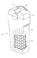
ディスペンサの1つの参考態様が図1に示される。ディスペンサ10は、錠剤,丸薬,キャンデー,ロゼンジ,ペレット,ビード,または他のかかる比較的小さな物品のための容器として作用する。ディスペンサ10は、一定量供給される錠剤14または他の小さな物品を貯蔵する中空ベース容器12を備える。ベース容器12は、ベース容器12に容易に装着され得る、ベース容器12の開口に嵌まるカバー16を有する。カバー16は、図1に見られる回転歯22などの手動アクチュエータによって制御され得る自己閉鎖開口18を備える。
One Reference Aspect de Isupensa is shown in FIG. The
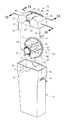
この参考態様のディスペンサを図2においてより良く見ることができる。ディスペンサの3つの一次要素は、中空ベース容器12、カバー16、および回転可能に設置されたホイール20である。カバー16は好ましくは、上部部分30および対向した側壁31を有する。上部カバー16は、中空ベース容器12内に貯蔵された物品を一定量供給することができる開口または孔18を有する。図2に示された参考態様において、開口孔は、ホイール20上の外歯22の部分がそれによってカバー16の上部部分30よりも上に延在することができる、側壁31の一方に近接した拡張溝39を備える。
The dispenser of this reference embodiment can be better seen in FIG. The three primary elements of the dispenser are a
ディスペンサのカバーを接着剤、テープ、または機械的連動要素などの様々な機構のいずれによってベース容器の開口を覆って装着させてもよい。図2に示された参考態様において、カバー16は、固定脚(locking feet)32によってベース容器12の開口部分42に接続される。固定脚32は、カバー16がベース容器の開口12の上に押される時にベース容器12の両側の開口44中にスライドして係合する、外向きに延在するタブ33を有するように形成される。
Adhesive cover de Isupensa, tape, or any by may be mounted over the opening of the base container of various mechanisms, such as mechanical interlocking elements. In the reference embodiment shown in FIG. 2, the
カバーは、ホイール20が回転可能に設置され得る軸受をさらに備える。図2に示された参考態様において、ホイール20を回転的に支持するための軸受は、ディスペンサカバー16の側壁31の各々に形成された半円状突出部分34からなる。ホイール20のための軸受は、ベース容器12の開口42の両側に対して補完する突出半円状部分36をさらに備えてもよい。
Cover further comprises a
ディスペンサのホイール20は好ましくは、軸およびこの軸から半径方向に延在する少なくとも3枚のフィンからなる。より好ましくは、ホイールは、軸から半径方向に延在し且つ当該軸の周りに相互に間隔をあけた少なくとも5枚のフィンを備え、最も好ましくは、ホイールは、軸から半径方向に延在する6〜10枚のフィンを備え、そのフィンが軸の周りに互いにほぼ等しく間隔をあけられている。図2に示された参考態様において、軸26から半径方向に延在するフィン21を有するホイール20が製造される。フィン21は好ましくは、一定量供給される物品の所望の量を収納するように空隙および寸法を定められる。軸26の対向端部は好ましくは、カバー16およびベース容器12の壁の半円状突出部分34および36によって形成された軸受に保持される突出ハブ24を有するように形成される。この参考態様において、ホイールは、ホイールの歯22を形成するのこ歯状縁を有するディスク形エンドキャップ28をさらに備える。集成プロセスの間に所望の位置にホイール20を配置するために使用できるアライメント穴29をエンドキャップ28に設けてもよい。ホイール20をカバー16内に設置する時に、カバー16内の細長い溝39を通して延在する歯22を押すことによって、それを手動で回転させることができる。
図2に示された参考態様によると、ホイール20が、カバー16内で回転可能であると同時にカバー16に挿入および係合され得る。好ましくは、充填されたベース容器12の開放端上にカバー16を装着させる前にカバー16およびホイール20を予備集成できるように、ホイール20をカバー16に嵌め込まれる。ホイール20が、カバー16の側壁31の対向した内面上の隆起リッジ37および38によってカバー16内の所定の位置に保持される。図2および4に見ることができるように、リッジ38が溝39に近接し、側壁31の内面から突き出るが、そこに隣接して溝39がカバー16の上面30に形成される。図3Aに最もよく見られるように、フィン21とは異なる方向を向いたディスク形キャップ28の表面は好ましくは、キャップ28の外面の周りに歯22のすぐ内側に延びているリップ27を有するように形成され、そのリップは、ホイールがカバー16に挿入される時に突出リッジ38の上にはみ出る。カバー16の反対側の面上の隆起リッジ37が、キャップ28の反対側のホイール20の面と係合する。図2に見ることができるように、軸26に隣接するフィン21の各々の縁が各々、カバー16の内側側壁31上の隆起リッジ37と係合するノッチ23を有する。好ましくは、隆起リッジ37は、いつでもフィン21のうちの少なくとも1枚の、ノッチ23と係合するように十分に長い。
When Ru good reference embodiment shown in FIG. 2, the
カバー16の上面30の裏面は、前記ホイール20の前記フィンと係合する1つまたは複数の隆起ボスを有する。図3Bおよび図4に示された参考態様において、第1の隆起ボス40および第2の隆起ボス41が、カバー16の裏面から孔18の両面の上に突き出る。ボス40および41が、回転ホイール20のフィン21の端部と接触するように十分に突き出るのがよい。図3Bに示された参考態様において、フィン21は各々、同じ角度だけ相互間隔をあけ、その角度は、2枚の隣接するフィンの端縁が孔18の幅とほぼ同じだけ相互間隔をあけるような幅である。好ましくは、ボス40および41は、フィン21の端部に隣接しており、1枚のフィンがカバー16の孔18の一方の縁と整列され、他のフィンが孔18の反対側の縁と整列している位置にフィンを保持する。ボス40および41は好ましくは、ホイールの1枚のフィンがボスの一方を通過している時にカバーが曲がることができるカバー上の場所に配置される。ホイールのフィン21がボス40および41を通過する時のホイール20の回転に対する望ましい耐性および望ましいクリック音に応じて、ボスの各面の角度をより鋭くするかまたはより緩やかにしてもよい。
The back surface of the
ディスペンサのカバー16およびホイール20は好ましくはプラスチックから製造され、それらは好ましくは、射出成形によって製造される。カバー16およびホイール20は各々、自体に容易に滑り合うことができる強プラスチックから製造されるのがよい。かかる材料は、ホイール20のブレード21の端縁が、破断せずにボス40および41を通過することを可能にする。強および硬質プラスチックはまた、ホイールの、カバー16内への嵌込みを改良する。低摩擦性質を有するプラスチックの使用は、ホイール20がカバー16内で、より容易に回ることを可能にする。カバー16およびホイール20のための1つの好ましいポリマー樹脂は、本願特許出願人によって販売されたデルリン(Delrin)(登録商標)アセタール樹脂などのアセタール樹脂である。カバー16およびホイール20の製造に用いられてもよい他のポリマー樹脂には、ポリアミド,ポリブチレンテレフタレート(PBT),ポリエチレンテレフタレート(PET),他のポリエステル,ポリカーボネート,アクリロニトリル−ブタジエン−スチレンコポリマー(ABS),およびポリオレフィンなどがある。1つの本発明の好ましい実施態様において、ホイール20は、歯22については軟質および可撓性のコポリエーテルエステルエラストマーおよびホイール20の残り部分については強および硬質アセタール樹脂など、1種類以上のポリマーから成形されてもよい。
ベース容器12は、軽量プラスチック、紙および厚紙材料など、より多種多様な材料からなってもよい。好ましい材料には、それらの低いコストおよびそれらが多様な形状に成形され得るために、ポリプロピレンおよびポリエチレンなどがある。図2に示されたベース容器12は略矩形の形状を有するが、ベース容器は、ディスペンサから一定量供給される物品の販売を促進するために様々な形状および寸法に成形され得ることが予想される。
図1〜図4に示されたディスペンサ10が作動されるとき、ディスペンサのベース容器12は、錠剤、キャンデー、ミント、丸薬または他の一定量供給される物品を保持する。ディスペンサのユーザーが錠剤または他の物品を一定量供給したいとき、ディスペンサをひっくり返し、1つまたは複数の錠剤がホイール20のフィン21の2つの間からカバー16の孔18に運ばれるまで、カバー16の溝39を通して延在する歯22を手動で回転させる。次いで、錠剤または他の物品が孔18を通してユーザーの空いた手に、またはどれかの表面に落ちることができる。有利には、ホイールを時計回りか、または反時計回りの方向に回すことができ、それにより、右利きおよび左利きのユーザーの両方がディスペンサを容易に作動させる。物品が一定量供給された後、孔18の両面にあるホイール20のフィン21はボス40および41によって固定位置に保持され、ディスペンサ内の錠剤または他の物品がディスペンサからこぼれ出ないようにする。錠剤または他の物品の所望の寸法および数が、ホイール20の回転のたびにおよびボス40または41の一方を通過するフィン21のクリック音のたびに一定量供給されるようにフィンの各セット間の容積を形成するために、フィン間の角度およびフィンの長さを設計および設定することができる。この参考形態のディスペンサによると、ホイールの回転のたびに一定量供給される物品の様々な物品寸法または数を収納するためにフィン間の比較的大きな区画を有するようにホイール、フィンおよびカバーを設計することができる。あるいは、ホイール20の回転のクリック音のたびにディスペンサが1つだけの物品を一定量供給するように、区画をより小さくし、一定量供給される物品の寸法にごく近い寸法にすることができる。
When the
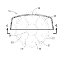
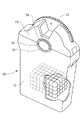
本発明の好ましい実施態様が図5〜図7に示される。図5〜図7に示されたディスペンサ50は、多くの点で、図1〜図4に関して上に記載されたディスペンサに似ている。図5〜図7のディスペンサ50における顕著な違いの1つは、ホイールのハブ54が、ディスペンサカバー58およびディスペンサ容器12の両面の側壁を通して延在することである。ディスペンサ容器12上の丸い軸受表面55およびディスペンサカバー58上の軸受表面56が、回転可能なホイール53の中心軸の対向端部のハブ54を支持する。図5〜図7に示されたディスペンサの第2の顕著な違いは、ホイール53上の外歯52が、図1〜図4に示されたディスペンサの歯よりも大きい、ホイールの弧の部分についてカバー58の溝59を突き出て作動をより容易にすることである。
Good preferable embodiment of the present invention is shown in FIGS. 5-7. The
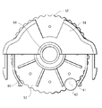
図5〜図7の実施態様のディスペンサにおける第3の顕著な違いは、カバー58と一体であり且つそこから下に延在する可撓性のガイドアーム60および61である。ガイドアーム60および61は、錠剤またはキャンデーの過負荷がホイールを動けなくするのを防ぐため、ホイール53のフィン間の空隙へのおよびホイール53の周りの錠剤またはキャンデーの流れを調節するのに役立つ。アームを破断することなくホイールのフィン間の過剰な錠剤がホイールのフィン間から出ることができるように、アーム60および61が強靭および可撓性にされる。この理由のために、カバー58およびアーム60および61がアセタール樹脂などの高強度プラスチックから成形される場合、有用である。
A third notable difference in the dispenser of the embodiment of FIGS. 5-7 is the
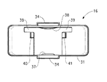
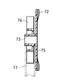
本発明の別の好ましい実施態様が図8−10に示される。図8−10に示されたディスペンサ70は、多くの点において、図5−7に関して上に記載されたディスペンサに似ている。図8−10のディスペンサ70における顕著な違いは、ホイールが、容器77およびカバー74の完全に外側に配置される作動ディスク75を備えることである。図8Aにおいて最もよく見られるように、作動ディスク75がホイール軸73上に設置されるかまたは一体化されるが、ホイール軸73から同様に延在するフィン76からずらされる。ホイールがディスペンサ70内に設置されるとき、ホイール軸73が、容器77上の丸い軸受表面55およびカバー74上の相応する軸受表面56によって保持される。ユーザーが錠剤またはキャンデーをディスペンサ70から一定量供給したいとき、ユーザーは単にディスペンサを上下さかさまにし、カバー74の孔を手の上かまたは物品が一定量供給される他の表面の上に置く。次いで、ユーザーは、所望の数の物品が孔を通して一定量供給されるまで、ホイール上のフィン76を回すために作動ディスク75上のリブ72を押すことができる。
Another preferred embodiment of the present invention is shown in FIGS. 8-10. The
本発明の特定の実施態様は前述の説明において記載されたが、本発明が、本発明の精神または本質的な属性から逸脱することなく多くの変更、置換えおよび再配置できることは、当業者には明らかであろう。本発明の範囲を示すとき、前述の明細書および図面ではなく、添付された特許請求の範囲を参照しなければならない。 While particular embodiments of the present invention have been described in the foregoing description, it will be apparent to those skilled in the art that the present invention can be modified, replaced, and rearranged without departing from the spirit or essential attributes of the invention. It will be clear. When indicating the scope of the invention, reference should be made to the appended claims rather than to the foregoing specification and drawings.
Claims (1)
一定量供給される物品を貯蔵するための空隙を有し、前記空隙に接続された開口を有するベース容器と、
前記ベース容器の前記開口に嵌まる寸法形状のカバーであって、前記ベース容器内に貯蔵された物品が一定量供給され得る孔およびこのカバーの内面にある少なくとも1つの隆起ボスを有するカバーと、
このカバーを前記ベース容器の開口を覆って装着させるための手段と、
前記カバーの内側に回転可能に設置されたホイールであって、軸およびこの軸から半径方向に延在し且つ当該軸の周りに相互に間隔をあけた少なくとも3枚のフィンを有し、このホイールの前記軸および前記フィンが前記カバーの内側で回転できると共に前記ベース容器内に貯蔵された物品をカバーの孔まで運ぶことができるように当該ホイールが前記カバーの内側に設置され、該ホイールが360度回転するたびに回転する前記フィンが前記カバーの内面にある前記隆起ボスと接触して通過するように整列しているホイールと、
前記カバーと一体に形成されて前記カバーから下方に延在し、前記ホイールのフィン間の空隙への物品の流れを調節するための可撓性のガイドアームと、
前記ディスペンサの外側から使用可能であり、前記カバーの内側の前記ホイールを手動で回転させるためのアクチュエータと、
前記カバーおよび前記ホイールのフィンがプラスチック樹脂から作られていることと
を具えたことを特徴とするディスペンサ。A dispenser for storing and supplying a small amount of small articles,
A base container having a gap for storing a certain amount of supplied articles, and having an opening connected to the gap;
A cover sized and shaped to fit into the opening of the base container, the cover having a hole through which a certain amount of articles stored in the base container can be supplied, and at least one raised boss on the inner surface of the cover;
Means for attaching the cover over the opening of the base container;
A wheel rotatably mounted inside the cover, comprising a shaft and at least three fins extending radially from the shaft and spaced from each other about the shaft The wheel is installed inside the cover so that the shaft and the fins can rotate inside the cover and can carry articles stored in the base container to the hole in the cover, and the wheel is 360 A wheel that is aligned so that the fin that rotates each time it rotates is in contact with the raised boss on the inner surface of the cover;
A flexible guide arm formed integrally with the cover and extending downward from the cover to regulate the flow of articles into the gap between the fins of the wheel;
An actuator usable from outside the dispenser, for manually rotating the wheel inside the cover;
A dispenser characterized in that the cover and the fin of the wheel are made of plastic resin.
Applications Claiming Priority (2)
| Application Number | Priority Date | Filing Date | Title |
|---|---|---|---|
| US42610902P | 2002-11-14 | 2002-11-14 | |
| PCT/US2003/036162 WO2004045986A1 (en) | 2002-11-14 | 2003-11-12 | Tablet dispenser |
Publications (3)
| Publication Number | Publication Date |
|---|---|
| JP2006506287A JP2006506287A (en) | 2006-02-23 |
| JP2006506287A5 JP2006506287A5 (en) | 2006-11-24 |
| JP4249708B2 true JP4249708B2 (en) | 2009-04-08 |
Family
ID=32326312
Family Applications (1)
| Application Number | Title | Priority Date | Filing Date |
|---|---|---|---|
| JP2004553597A Expired - Fee Related JP4249708B2 (en) | 2002-11-14 | 2003-11-12 | Pill dispenser |
Country Status (7)
| Country | Link |
|---|---|
| US (1) | US7017780B2 (en) |
| EP (1) | EP1581442A1 (en) |
| JP (1) | JP4249708B2 (en) |
| KR (1) | KR100993722B1 (en) |
| CN (1) | CN100445181C (en) |
| HK (1) | HK1088584A1 (en) |
| WO (1) | WO2004045986A1 (en) |
Families Citing this family (35)
| Publication number | Priority date | Publication date | Assignee | Title |
|---|---|---|---|---|
| KR100578035B1 (en) | 2004-06-23 | 2006-05-11 | 박재태 | A dispenser for foods or medicines |
| DE602006014717D1 (en) | 2005-03-22 | 2010-07-15 | Bayer Healthcare Llc | CARTRIDGE WITH WHEEL FOR OPENING CLOSURE |
| TW200708735A (en) * | 2005-04-25 | 2007-03-01 | Bayer Healthcare Llc | Sensor release mechanism for a test meter |
| US7559436B2 (en) * | 2005-05-24 | 2009-07-14 | Webb Candy, Inc. | Small item dispenser |
| US7575721B2 (en) * | 2005-06-06 | 2009-08-18 | Cepheid | Method and apparatus for storing and dispensing reagent beads |
| US7143719B1 (en) * | 2005-07-06 | 2006-12-05 | Giddens Susan L | Pet treat dispenser assembly with clicker |
| CN101370720A (en) * | 2005-12-16 | 2009-02-18 | 米德韦斯瓦科公司 | Child resistant dispenser |
| US7484409B2 (en) * | 2006-03-28 | 2009-02-03 | Briggs & Stratton Corporation | Fluid level switch |
| JP4840650B2 (en) * | 2006-05-29 | 2011-12-21 | 株式会社吉野工業所 | Tablet container |
| US20070289985A1 (en) * | 2006-06-05 | 2007-12-20 | Bieger Walter I | Small item dispenser with maze |
| US20100065577A1 (en) * | 2008-06-11 | 2010-03-18 | Coughlin Daniel P | Apparatus for Dispensing Treats |
| US8141727B2 (en) * | 2009-01-17 | 2012-03-27 | Patrick Mulligan | Water bottle with dosage in a dispenser cap |
| GB2473302B (en) * | 2009-12-18 | 2011-07-27 | Magmatic Ltd | Storage containers |
| CN102327873A (en) * | 2011-09-14 | 2012-01-25 | 江苏天鹏电源有限公司 | Feeding device in battery screening machine |
| US9592948B2 (en) * | 2011-10-03 | 2017-03-14 | MerchSource, LLC | Dispenser stir stick |
| US8998033B2 (en) * | 2012-04-19 | 2015-04-07 | Paul Maurice HUARD | Material dispenser |
| CA2922088C (en) * | 2013-08-27 | 2018-09-18 | Suhjun Park | Content receiving device, opening/closing mechanism, and container mechanism comprising the same |
| CN103552793A (en) * | 2013-10-16 | 2014-02-05 | 深圳市海川物联科技有限公司 | Medicine storing and discharging structure and automatic medicine discharging machine comprising same |
| CN103848107A (en) * | 2014-03-13 | 2014-06-11 | 中山火炬职业技术学院 | Candy packing box |
| WO2018207129A2 (en) * | 2017-05-11 | 2018-11-15 | Log Plastic Products (1993) Ltd. | Kits and bottle inserts |
| WO2016137186A1 (en) * | 2015-02-26 | 2016-09-01 | 박현수 | Passing device, valve, containing apparatus having same, contents moving apparatus and contents apparatus |
| EP3263484A4 (en) | 2015-02-26 | 2018-11-14 | PARK, Suhjun | Passing device, valve, containing apparatus having same, contents moving apparatus and contents apparatus |
| AU2016201131B2 (en) * | 2015-03-30 | 2020-04-02 | Manrex Limited | Dispensing container for blister pack of medication |
| CN104843311B (en) * | 2015-05-26 | 2017-04-12 | 邵晖 | Container cover with metering distributor |
| KR101874328B1 (en) | 2016-02-01 | 2018-07-05 | 박서준 | Contents passing device, valve, and containing apparatus, contents moving apparatus and contents apparatus having the contents passing device and valve |
| US10407235B2 (en) * | 2016-11-30 | 2019-09-10 | My Favorite Company, Inc. | Candy dispenser |
| CN106742810B (en) * | 2017-03-09 | 2018-09-28 | 广东工业大学 | A kind of quantitative sugar device |
| US11160629B2 (en) * | 2017-09-12 | 2021-11-02 | Merit Medical Systems, Inc. | Medical device dispenser and method of use |
| KR102066128B1 (en) * | 2017-11-24 | 2020-01-15 | 박가빈 | A medicine case caterpillar |
| US10896750B2 (en) * | 2018-04-24 | 2021-01-19 | Arrix, Inc. | Systems and methods for medication management |
| US11335448B2 (en) | 2018-04-24 | 2022-05-17 | Arrix, Inc. | Systems and methods for medication management |
| CN109573352B (en) * | 2019-01-16 | 2023-09-29 | 夏敏 | Cathartic bottle device for component guiding taking |
| CN110498116B (en) * | 2019-08-08 | 2021-05-04 | 六安市我罗生工业设计有限公司 | Go out convenient domestic birds, beasts and eggs bin of egg |
| CN212891574U (en) * | 2020-07-29 | 2021-04-06 | 洲际大品牌有限责任公司 | Packing box (Chinese character' jiangsu |
| KR102395334B1 (en) * | 2021-05-13 | 2022-05-09 | 박경도 | A quantitative discharge device for contents and container with the same |
Family Cites Families (8)
| Publication number | Priority date | Publication date | Assignee | Title |
|---|---|---|---|---|
| FR1317936A (en) * | 1963-05-10 | |||
| US3276636A (en) * | 1965-04-12 | 1966-10-04 | Owens Illinois Inc | Article dispenser having a rotary trap chamber |
| US4428502A (en) * | 1980-03-25 | 1984-01-31 | Veltri Douglas F | Lockable pocket-size tablet dispensing device |
| DE29514137U1 (en) | 1995-09-02 | 1995-10-26 | Bramlage GmbH, 49393 Lohne | Pill dispenser |
| JPH09193974A (en) * | 1996-01-19 | 1997-07-29 | Yoshino Kogyosho Co Ltd | Tablet housing container |
| US6112942A (en) * | 1997-02-28 | 2000-09-05 | Merck & Co., Inc. | Tablet dispensing cap |
| JP2002529338A (en) * | 1998-11-13 | 2002-09-10 | ノボ ノルディスク アクティーゼルスカブ | Tablet dispenser |
| WO2001024124A2 (en) * | 1999-09-25 | 2001-04-05 | Schmidt, Horst | Modular goods dispensing unit for a goods vending machine |
-
2003
- 2003-11-12 WO PCT/US2003/036162 patent/WO2004045986A1/en active Application Filing
- 2003-11-12 EP EP03781919A patent/EP1581442A1/en not_active Withdrawn
- 2003-11-12 KR KR1020057008650A patent/KR100993722B1/en not_active IP Right Cessation
- 2003-11-12 CN CNB2003801087604A patent/CN100445181C/en not_active Expired - Fee Related
- 2003-11-12 JP JP2004553597A patent/JP4249708B2/en not_active Expired - Fee Related
- 2003-11-14 US US10/714,117 patent/US7017780B2/en not_active Expired - Fee Related
-
2006
- 2006-08-14 HK HK06109002.1A patent/HK1088584A1/en not_active IP Right Cessation
Also Published As
| Publication number | Publication date |
|---|---|
| KR20050075410A (en) | 2005-07-20 |
| US20040094566A1 (en) | 2004-05-20 |
| JP2006506287A (en) | 2006-02-23 |
| EP1581442A1 (en) | 2005-10-05 |
| HK1088584A1 (en) | 2006-11-10 |
| WO2004045986A1 (en) | 2004-06-03 |
| CN1738751A (en) | 2006-02-22 |
| US7017780B2 (en) | 2006-03-28 |
| KR100993722B1 (en) | 2010-11-10 |
| CN100445181C (en) | 2008-12-24 |
Similar Documents
| Publication | Publication Date | Title |
|---|---|---|
| JP4249708B2 (en) | Pill dispenser | |
| US6176397B1 (en) | Granular material container and dispenser | |
| RU2429178C2 (en) | Dispenser for pelleted goods | |
| US7320415B2 (en) | Condiment dispensing container and carousel | |
| US8186544B2 (en) | Dispensing device for edible goods and/or novelties | |
| US20100147867A1 (en) | Pill dispenser | |
| US8215167B2 (en) | Scoop having a parking anchor for measuring and dispensing powdered or granular material | |
| JP2017530068A (en) | Confectionery container and dispenser with spill prevention function | |
| US20160068313A1 (en) | Dispenser assembly | |
| US20220048693A1 (en) | Confection dispenser system | |
| WO2009064945A1 (en) | Dual dispenser pen | |
| JP5264930B2 (en) | Dispenser with internal spring actuation mechanism | |
| US5779095A (en) | Portable gumball dispenser | |
| US6561379B1 (en) | Packaging box for tablets | |
| US6354470B1 (en) | Dispenser package | |
| KR200359435Y1 (en) | The solid of discharge device | |
| WO2002094685A1 (en) | Article takeout container | |
| JP3163525U (en) | Drawer container |
Legal Events
| Date | Code | Title | Description |
|---|---|---|---|
| A521 | Request for written amendment filed |
Free format text: JAPANESE INTERMEDIATE CODE: A523 Effective date: 20061006 |
|
| A621 | Written request for application examination |
Free format text: JAPANESE INTERMEDIATE CODE: A621 Effective date: 20061006 |
|
| A131 | Notification of reasons for refusal |
Free format text: JAPANESE INTERMEDIATE CODE: A131 Effective date: 20080617 |
|
| A601 | Written request for extension of time |
Free format text: JAPANESE INTERMEDIATE CODE: A601 Effective date: 20080917 |
|
| A602 | Written permission of extension of time |
Free format text: JAPANESE INTERMEDIATE CODE: A602 Effective date: 20080925 |
|
| A601 | Written request for extension of time |
Free format text: JAPANESE INTERMEDIATE CODE: A601 Effective date: 20081016 |
|
| A602 | Written permission of extension of time |
Free format text: JAPANESE INTERMEDIATE CODE: A602 Effective date: 20081023 |
|
| A521 | Request for written amendment filed |
Free format text: JAPANESE INTERMEDIATE CODE: A523 Effective date: 20081114 |
|
| TRDD | Decision of grant or rejection written | ||
| A01 | Written decision to grant a patent or to grant a registration (utility model) |
Free format text: JAPANESE INTERMEDIATE CODE: A01 Effective date: 20081216 |
|
| A01 | Written decision to grant a patent or to grant a registration (utility model) |
Free format text: JAPANESE INTERMEDIATE CODE: A01 |
|
| A61 | First payment of annual fees (during grant procedure) |
Free format text: JAPANESE INTERMEDIATE CODE: A61 Effective date: 20090115 |
|
| FPAY | Renewal fee payment (event date is renewal date of database) |
Free format text: PAYMENT UNTIL: 20120123 Year of fee payment: 3 |
|
| R150 | Certificate of patent or registration of utility model |
Free format text: JAPANESE INTERMEDIATE CODE: R150 |
|
| FPAY | Renewal fee payment (event date is renewal date of database) |
Free format text: PAYMENT UNTIL: 20130123 Year of fee payment: 4 |
|
| FPAY | Renewal fee payment (event date is renewal date of database) |
Free format text: PAYMENT UNTIL: 20140123 Year of fee payment: 5 |
|
| LAPS | Cancellation because of no payment of annual fees |