JP4249437B2 - Adsorption heat pump, adsorption heat pump operation method, and vehicle air conditioner using adsorption heat pump - Google Patents
Adsorption heat pump, adsorption heat pump operation method, and vehicle air conditioner using adsorption heat pump Download PDFInfo
- Publication number
- JP4249437B2 JP4249437B2 JP2002175356A JP2002175356A JP4249437B2 JP 4249437 B2 JP4249437 B2 JP 4249437B2 JP 2002175356 A JP2002175356 A JP 2002175356A JP 2002175356 A JP2002175356 A JP 2002175356A JP 4249437 B2 JP4249437 B2 JP 4249437B2
- Authority
- JP
- Japan
- Prior art keywords
- adsorption
- zeolite
- adsorbent
- heat pump
- ppm
- Prior art date
- Legal status (The legal status is an assumption and is not a legal conclusion. Google has not performed a legal analysis and makes no representation as to the accuracy of the status listed.)
- Expired - Fee Related
Links
Images


Landscapes
- Drying Of Gases (AREA)
- Solid-Sorbent Or Filter-Aiding Compositions (AREA)
- Sorption Type Refrigeration Machines (AREA)
Description
【0001】
【発明の属する技術分野】
本発明は、ゼオライトを含む吸着ヒートポンプ用水蒸気吸着材およびこの水蒸気吸着材を用いた吸着ヒートポンプ、該ヒートポンプを用いた車両用空調装置等に関する。
【0002】
【従来の技術】
吸着ヒートポンプや除湿空調装置において吸着材が用いられるが、吸着質、例えば水を吸着した吸着材を再生するために、吸着材を加熱して吸着質を脱着させ、乾燥した吸着材を吸着質の吸着に使用する温度に冷却して再度吸着質の吸着に使用する。
【0003】
吸着材から吸着質を脱着させるために、比較的高温(120℃以上)の排熱または温熱を利用する吸着式ヒートポンプが既に実用化されている。しかし一般にコジェネレーション機器、燃料電池、自動車エンジンの冷却水や太陽熱などによって得られる熱は100℃以下と比較的低温であるため、現在実用化されている吸着式ヒートポンプの駆動熱源としては利用できず、100℃以下、更には60℃〜80℃の低温排熱の有効利用が求められていた。
【0004】
吸着式ヒートポンプの動作原理は同じでも、利用可能な熱源温度によって吸着材に求められる吸着特性が大きく異なる。例えば、高温側の熱源として用いようとするガスエンジンコージェネレーションや固体高分子型燃料電池の排熱温度は60℃〜80℃であり、自動車エンジンの冷却水の温度は85℃〜90℃である。
【0005】
そして、乾燥した吸着材を冷却するための熱源の温度も装置の設置場所によって異なる。例えば自動車の場合はラジエターで得られる温度であり、ビルや住宅などでは水冷塔や河川水などの温度である。つまり、吸着ヒートポンプの操作温度範囲は、ビルなどに設置する場合には低温側が25℃〜35℃、高温側が60℃〜80℃、自動車などに設置する場合には低温側が30℃〜40℃、高温側が85℃〜90℃程度である。このような低温排熱を有効利用するために、低温側熱源と高温側熱源の温度差が小さくても駆動できる装置が望まれている。
【0006】
吸着材の周囲が比較的高い温度でも装置が充分に作動するためには、吸着質を低相対蒸気圧で吸着させる必要があり、また使用する吸着材を少量にして装置を小型化するためには吸着材の吸脱着量が多い必要がある。そして吸着質の脱着(吸着材の再生)に低温の熱源を利用するためには脱着温度が低い必要がある。すなわち吸着ヒートポンプまたは除湿空調装置に用いる吸着材として(1)吸着質を低い相対蒸気圧で吸着し、(2)吸脱着量が多く、(3)吸着質を高い相対蒸気圧で脱着する吸着材が望まれている。
【0007】
【発明が解決しようとする課題】
本発明は水蒸気を低相対蒸気圧域で吸脱着する吸着材および該吸着材を用いた効率の良い吸着ヒートポンプの提供を目的としてなされたものである。
【0008】
【課題を解決するための手段】
本発明者らは、上記の課題を解決するために鋭意検討した結果、吸着ヒートポンプなどの吸着質の吸脱着を装置の駆動源とする装置に適した水蒸気吸着材を見いだした。
すなわち本発明の要旨は、吸着質、吸着質を吸脱着する吸着材を備えた吸脱着部、該吸脱着部に連結された吸着質の蒸発を行う蒸発部、および該吸脱着部に連結された吸着質の凝縮を行う凝縮部を備えた吸着ヒートポンプの運転方法であって、前記吸着材が、ゼオライトを含む水蒸気吸着材であって、該ゼオライトが骨格構造にアルミニウム、リンおよびケイ素を含み、かつ、該ゼオライトの29Si−MAS−NMRスペクトルにおける−108ppm〜−123ppmの信号強度の積分強度面積が−70ppm〜−123ppmの信号強度の積分強度面積に対して10%以下であり、前記吸着材から前記吸着質を脱着して前記吸着材を再生する際に加熱する熱媒の温度が100℃以下であることを特徴とする吸着ヒートポンプの運転方法に存する。
本発明の他の要旨は、吸着質、吸着質を吸脱着する吸着材を備えた吸脱着部、該吸脱着部に連結された吸着質の蒸発を行う蒸発部、および該吸脱着部に連結された吸着質の凝縮を行う凝縮部を備えた吸着ヒートポンプの運転方法であって、前記吸着材が、ゼオライトを含む水蒸気吸着材であって、該ゼオライトが骨格構造にアルミニウム、リンおよびケイ素を含み、かつ、該ゼオライトの29Si−MAS−NMRスペクトルにおける−108ppm〜−123ppmの信号強度の積分強度面積が−70ppm〜−123ppmの信号強度の積分強度面積に対して10%以下であり、前記吸着材から前記吸着質を脱着して前記吸着材を再生する際に加熱する熱媒の温度が60〜95℃であり、前記凝縮部の温度が30〜40℃であることを特徴とする吸着ヒートポンプの運転方法に存する。
本発明のさらに他の要旨は、吸着質、吸着質を吸脱着する吸着材を備えた吸脱着部、該吸脱着部に連結された吸着質の蒸発を行う蒸発部、および該吸脱着部に連結された吸着質の凝縮を行う凝縮部を備えた吸着ヒートポンプであって、前記吸着材から前記吸着質を脱着して前記吸着材を再生する際に加熱する熱媒の温度を100℃以下とし、前記吸着材が、ゼオライトを含む水蒸気吸着材であって、該ゼオライトが骨格構造にアルミニウム、リンおよびケイ素を含み、かつ、前記ゼオライトの29Si−MAS−NMRスペクトルにおける−108ppm〜−123ppmの信号強度の積分強度面積が−70ppm〜−123ppmの信号強度の積分強度面積に対して10%以下であり、前記ゼオライトの骨格構造に含まれるアルミニウム、リンおよびケイ素の原子の存在割合が下記式(1)、(2)および(3)
0.001≦x≦0.3 ・・・(1)
(式中、xは骨格構造のアルミニウム、リン、およびケイ素の合計に対するケイ素のモル比を示す)
0.3≦y≦0.6 ・・・(2)
(式中、yは骨格構造のアルミニウム、リン、およびケイ素の合計に対するアルミニウムのモル比を示す)
0.3≦z≦0.6 ・・・(3)
(式中、zは骨格構造のアルミニウム、リン、およびケイ素の合計に対するリンのモル比を示す)
を満足し、前記ゼオライトが、水蒸気吸着等温線において相対蒸気圧0.05以上、0.30以下の範囲で相対蒸気圧が0.15変化したときに水の吸着量変化が0.18g/g以上の相対蒸気圧域を有するものである、ことを特徴とする吸着ヒートポンプに存する。
本発明のさらに他の要旨は、上記吸着ヒートポンプを車両室内の空調に使用することを特徴とする車両用空調装置に存する。
【0009】
【発明の実施の形態】
まず、本発明の吸着ヒートポンプの動作原理等について説明する。
吸着ヒートポンプの操作蒸気圧範囲は、高温熱源温度Thigh、低温熱源温度Tlow1、低温熱源温度Tlow2および冷熱生成温度Tcoolから求められる脱着側相対蒸気圧φ1と吸着側相対蒸気圧φ2によって決定される。
【0010】
φ1およびφ2は次式(a)および(b)
脱着側相対蒸気圧φ1=平衡蒸気圧(Tlow1)/平衡蒸気圧(Thigh)…(a)
吸着側相対蒸気圧φ2=平衡蒸気圧(Tcool)/平衡蒸気圧(Tlow2)…(b)
により算出でき、φ1とφ2との間が操作可能な相対蒸気圧範囲である。
【0011】
ここで、高温熱源温度Thighは吸着材から吸着質を脱着して吸着材を再生する際に加熱する熱媒の温度を、低温熱源温度Tlow1は凝縮部の吸着質の温度を、低温熱源温度Tlow2は再生後の吸着材を吸着に共する際に冷却する熱媒の温度を、冷熱生成温度Tcoolは蒸発部の吸着質の温度、すなわち生成した冷熱の温度を意味する。平衡蒸気圧は吸着質の平衡蒸気圧曲線を用いて、温度から求めることができる。
【0012】
以下、吸着質が水である場合の操作蒸気圧範囲を例示する。高温熱源温度Thighが80℃、低温熱源温度Tlow1が30℃、冷熱生成温度Tcoolが10℃の場合、操作蒸気圧範囲はφ1〜φ2=0.09〜0.29である。同様に高温熱源温度が60℃の場合、操作相対水蒸気圧範囲はφ1〜φ2=0.21〜0.29である。また、自動車エンジンの排熱を利用して吸着ヒートポンプを駆動する場合については特開2000−140625号公報に詳細に記載されている。この報告を基に推算すると、高温熱源温度約90℃、低温熱源温度30℃である。この場合、操作相対水蒸気圧範囲はφ1〜φ2=0.06〜0.29である。
【0013】
以上より、ガスエンジンコージェネレーション、固体高分子型燃料電池または自動車エンジンの排熱を利用して吸着ヒートポンプを駆動する場合、操作相対水蒸気圧範囲はφ1〜φ2=0.05〜0.30、さらに限定すればφ1〜φ2=0.06〜0.29となると考えられる。つまり、加熱によって相対水蒸気圧を下げて吸着材を再生する際に、相対水蒸気圧が0.05、好ましくは0.06以上の範囲で脱着が完了しなければならない。一方、吸着という点では、相対蒸気圧0.30、好ましくは0.29以下の範囲で充分な吸着量が得られなければならない。つまり、この操作湿度範囲の中で吸着量の変化が大きい材料が好ましい。したがって、相対蒸気圧の下限が0.05、好ましくは0.06、上限が0.30、好ましくは0.29の範囲、すたわち相対蒸気圧の範囲はこれら下限と上限の組み合わせから選ばれ、好ましくは0.05〜0.30、より好ましくは0.06〜0.29の範囲において吸着量が大きく変化する材料が適当である。
【0014】
例えば吸着ヒートポンプにより、3.0kW(=10,800kJ/hr)の冷房能力を得る場合について想定する。ここで、3.0kWは一般的な自動車のエアコンに使用されるエアコンの冷房能力である。吸着ヒートポンプの容量は、種々の車両のエンジンルーム調査から少なくとも15リットル以下であることが望ましいと考えられる。
【0015】
次に、15リットル以下の容量の中に充填可能な吸着剤重量を求める。
エンジンルームに載せるべき部品としては吸着塔本体、蒸発器、凝縮器および制御バルブ類がある。これらを概略一体に形成したアッセンブリを15リットル以下の容量にする必要がある。我々の検討では、蒸発器と凝縮器とバルブ類の体格はおよそ4.5リットルで形成できると考えられる。従って吸着塔本体の容量はおよそ10.5リットル以下である。吸着塔内における吸着剤の充填率および吸着剤のかさ密度は、通常、それぞれ約30%、約0.6kg/リットルであるので、充填可能な吸着剤重量(W)は10.5×30%×0.6=1.89kg程度である。
【0016】
次に吸着剤に求められる特性について説明する。
吸着式ヒートポンプでの冷房能力Rは次式Aで表される。
R=(W・ΔQ・ηC・ΔH/τ)・ηh (式A)
ここでWは吸着塔1台(片側)に充填される吸着剤重量、ΔQは吸着時と脱離時の条件における平衡吸着量振幅で前記吸着量差(Q2−Q1)、ηCは平衡吸着振幅ΔQに対する切り替え時間内の実際の吸着振幅の割合を示す吸着振幅効率、ΔHは水の蒸発潜熱、τは吸着工程と脱離工程との切り替え時間、ηhは吸着剤や熱交換器が温水温度と冷却水温度との間を温度変化することによるヒートマス損失を考慮したヒートマス効率、を示す。
【0017】
Rは前述のように3kW、Wは1.89kg/2=0.95kgである。また我々の過去の検討から、τはおよそ60secが適当であり、ΔH、ηC、ηhの値はそれぞれおよそ2500kJ/kg、0.6、0.85であることが得られているので(式A)からΔQを求めると、
ΔQ = R/W/ηC/ΔH・τ/ηh=3.0/0.95/0.6/2500・60/0.85 = 0.149kg/kg
となる。すなわち自動車用吸着式ヒートポンプに用いる吸着剤としては、ΔQは0.15g/g以上、0.18g/g以上が好ましく、0.20g/g以上が更に好ましい。
【0018】
以上、自動車への適用を前提に説明したが、上記の特性を満足するものであれば定置用など他の用途にも十分適用可能であることは言うまでもない。
吸着ヒートポンプは、吸着材が吸着質を吸脱着する能力を駆動源として利用している。吸着ヒートポンプにおいては吸着質として、水、エタノールおよびアセトンなどが使用できるが、中でも安全性、価格、蒸発潜熱の大きさから、水が最も好ましい。吸着質は蒸気として吸着材に吸着されるが、吸着材は、狭い相対蒸気圧範囲で吸着量の変化が大きい材料が好ましい。狭い相対蒸気圧範囲で吸着量の変化が大きいと、同じ条件で同等の吸着量を得るために必要な吸着材の量を減らし、冷却熱源と加熱熱源の温度差が小さくても吸着ヒートポンプを駆動できるからである。
【0019】
本発明の水蒸気吸着材はゼオライトを含有する水蒸気吸着材であって、該ゼオライトに一つの特徴を有するものである。水蒸気吸着材は、直接大気中の水蒸気を吸着する除湿器、デシカント空調装置、調湿建材などに用いられ、また、吸着ヒートポンプのように真空中で水蒸気しか存在しない環境で吸着材として使用される。
【0020】
本発明の水蒸気吸着材に含まれるゼオライト(以下これを「本発明のゼオライト」ということがある)に関して以下詳細に説明する。
本発明のゼオライトは、骨格構造にアルミニウム、リンおよびケイ素を含む。
本発明のゼオライトの29Si−MAS−NMRスペクトルにおける−108ppm〜−123ppmの信号強度の積分強度面積は、−70ppm〜−123ppmの信号強度の積分強度面積に対して10%以下であって、好ましくは9.5%以下、さらに好ましくは9%以下のゼオライトである。上記の強度面積比が大きすぎると低相対蒸気圧域での吸脱着特性が劣る。
【0021】
また、29Si−MAS−NMRスペクトルにおける−70ppm〜−92ppmの信号強度の積分強度面積は、−70ppm〜−123ppmの信号強度の積分強度面積に対して25%以上であって、好ましくは50%以上である。
なお、本発明における29Si−MAS−NMRスペクトルは、テトラメチルシランを標準物質として、水デシケーター中で試料を室温で一昼夜保存して水を飽和吸着させた試料を以下の条件で測定したものである。
装置:Chemagnetic CMX−400
プローブ:7.5mmMASプローブ
共鳴周波数:79.445MHz
パルス幅:5.0マイクロ秒
パルス系列:シングルパルス
待ち時間:60秒
回転数:4000rps
ゼオライトの29Si−MAS−NMRのスペクトルは、ゼオライト中のSiの結合状態についての情報を与え、ピークの位置や分布によりSi結合状態を知ることができる。
【0022】
本発明のゼオライトはアルミニウム、リンおよびケイ素を含むが、ゼオライト中のケイ素原子はSiO2を単位として存在している。ここで、29Si−MAS−NMRのスペクトルにおいて、−90ppm付近のピークはケイ素原子が酸素原子を介して4個のケイ素原子以外の原子と結合しているものである。これに対して−110ppm付近のピークは、ケイ素原子が酸素原子を介して4個のケイ素原子と結合しているものである。すなわち、−110ppm付近のピーク強度が大きいゼオライトはケイ素原子同士が集まり、ゼオライトにおけるケイ素原子の分散性が低いことを意味する。
【0023】
Siの分散性がゼオライトの吸着特性に影響し、後述する様に、ケイ素原子の分散性が高いゼオライトが特に吸着ヒートポンプの吸着材に適した性能を発揮すると考えられる。
本発明のゼオライトにおいて、アルミニウム、リンおよびケイ素の原子の存在割合は下記式(1)、(2)および(3)
0.001≦x≦0.3 ・・・(1)
(式中、xは骨格構造のアルミニウムとリンとケイ素の合計に対するケイ素のモル比を示す)
0.3≦y≦0.6 ・・・(2)
(式中、yは骨格構造のアルミニウムとリンとケイ素の合計に対するアルミニウムのモル比を示す)
0.3≦z≦0.6 ・・・(3)
(式中、zは骨格構造のアルミニウムとリンとケイ素の合計に対するリンのモル比を示す)
を満足するものが好ましい。
ゼオライト中の上記原子の存在割合のなかで、上記式(1)におけるケイ素の存在割合(x)が、0.25以下が好ましく、0.2以下がより好ましい。
【0024】
更に上記の通り、ケイ素原子の分散性が高いものが本発明の吸着性の性能の点で好ましいと考えられ、かかる分散性を示すものを得るためには、上記ケイ素の存在割合(x)が、0.09以下であると有利である傾向があり、0.085以下が更に好ましく、特に0.08以下が好ましい。又、上記ケイ素の存在割合(x)が0.003以上が好ましく、0.005以上が更に好ましく、特に0.01以上が好ましい。
【0025】
また、上記の組成のケイ素、アルミニウム、リンの範囲内であるならば、骨格内に他の元素が含まれていても良い。他の元素としては、リチウム、マグネシウム、チタン、ジルコニウム、バナジウム、クロム、マンガン、鉄、コバルト、ニッケル、パラジウム、銅、亜鉛、ガリウム、ゲルマニウム、砒素、スズ、カルシウム、硼素などがあげられる。また、このゼオライトは他のカチオンと交換可能なカチオン種を持つものを含むが、その場合のカチオンとしては、プロトン、Li、Na、Kなどのアルカリ元素、Mg、Caなどのアルカリ土類元素、La、Ce等の希土類元素、Fe、Co、Ni等の遷移金属元素などがあげられるが、プロトン、アルカリ元素、アルカリ土類元素が好ましい。
【0026】
上記の原子割合は元素分析により決定することができる。元素分析値は試料を塩酸水溶液で加熱溶解させ、ICP分析により求める。
本発明のゼオライトは天然のゼオライトでも人工のゼオライトでもよく、例えば人工のゼオライトではInternational Zeolite Association(IZA)の規定によるアルミノシリケート類、アルミノフォスフェート類などが含まれる。
【0027】
本発明のゼオライトの構造は、International ZeoliteAssociation(IZA)が定めるコードで示すと、通常AEI、AFR、AFS、AFT、AFX、AFY、AHT、CHA、DFO、ERI、FAU、GIS、LEV、LTA、VFIであり、AEI、GIS、CHA、VFI、AFS、LTA、FAU、AFYが好ましく、CHAが最も好ましい。
【0028】
ゼオライトの構造は粉末XRD(粉末X線回折)によりXRDパターンを測定し、Collection Of Simulated XRD PowderPatterns For Zeolites(1996,ELSEVIER)に記載されたXRDパターンと比較して決定する。
また、IZAのAtlas Of Zeolite Structure Types(1996,ELSEVIER)に構造とフレームワーク密度の関係が記載されており、構造からフレームワーク密度を知ることができる。
【0029】
本発明のゼオライトのフレームワーク密度は、通常10.0T/1000A3以上16.0T/1000A3以下、好ましくは10.0T/1000A3以上15.0T/1000A3以下のゼオライトである。
本発明のゼオライトとしては、水蒸気吸着等温線において通常相対蒸気圧0.05〜0.30の範囲で相対蒸気圧が0.15変化したときに、水の吸着量が0.18g/g以上変化するゼオライトであるのが好ましく、0.20g/g以上変化するゼオライトが更に好ましい。また、相対蒸気圧0.05〜0.20の範囲で水の吸着量が0.18g/g以上変化するゼオライトが更に好ましく、0.20g/g以上変化するゼオライトが最も好ましい。そして、水蒸気吸着等温線において相対蒸気圧0.05での吸着量は、通常0.15g/g以下であり、0.12g/g以下が好ましく、更に0.10g/g以下、特に0.07g/g以下が好ましく、0.05g/g以下が最も好ましい。
【0030】
なお、本発明における水蒸気吸着材の水蒸気吸着等温線の測定は、以下の条件で行う。
吸着等温線測定装置:ベルソーブ18(日本ベル(株))
空気高温槽温度:50℃
吸着温度:25℃
初期導入圧力:3.0torr
導入圧力設定点数:0
飽和蒸気圧:23.76mmHg
平衡時間:500秒
前処理:200℃、5時間真空引き
本発明のゼオライトは上記した特性を有する限りその製造方法は特に限定されないが、例えば特公平4−37007号公報、特公平5−21844号公報、特公平5−51533号公報、米国特許第4440871号公報等に記載の方法に準じて以下の方法により製造することができる。
【0031】
まず、アルミニウム源、シリカ源、リン酸源およびテンプレートを混合して水性ゲルを調合する。
アルミニウム源としては、擬ベーマイト、アルミニウムイソプロポキシド、水酸化アルミニウム、アルミナゾル、アルミン酸ナトリウムなどが用いられる。
シリカ源としては、fumedシリカ、シリカゾル、コロイダルシリカ、水ガラス、ケイ酸エチル、ケイ酸メチルなどが用いられる。
【0032】
リン酸源としてはリン酸が用いられる。また、リン酸アルミニウムを用いる事もできる。
テンプレートとしては、テトラメチルアンモニウム、テトラエチルアンモニウム、テトラプロピルアンモニウム、テトラブチルアンモニウム等の4級アンモニウム塩、モルホリン、ジ−n−プロピルアミン、トリ−n−プロピルアミン、トリ−n−イソプロピルアミン、トリエチルアミン、トリエタノールアミン、ピペリジン、シクロヘキシルアミン、2−メチルピリジン、N,N−ジメチルベンジルアミン、N,N−ジエチルエタノールアミン、ジシクロヘキシルアミン、N,N−ジメチルエタノールアミン、コリン、N,N‘−ジメチルピペラジン、1,4−ジアザビシクロ(2,2,2)オクタン、N−メチルジエタノールアミン、N−メチルエタノールアミン、N−メチルピペリジン、3−メチルピペリジン、N−メチルシクロヘキシルアミン、3−メチルピリジン、4−メチルピリジン、キヌクリジン、N,N’−ジメチル−1,4−ジアザビシクロ−(2,2,2)オクタンイオン、ジ−n−ブチルアミン、ネオペンチルアミン、ジーn−ペンチルアミン、イソプロピルアミン、t−ブチルアミン、エチレンジアミン、ピロリジン、2−イミダゾリドン、ジ−イソプロピル−エチルアミン、ジメチルシクロヘキシルアミン、N−メチル−n−ブチルアミン、ヘキサメチレンイミン、等の1級アミン、2級アミン、3級アミン、ポリアミンが用いられる。これらは混合して用いても良い。このなかでもモルホリン、トリエチルアミン、シクロヘキシルアミン、イソプロピルアミン、ジ−イソプロピル−エチルアミン、N−メチル−n−ブチルアミン、テトラエチルアンモニウムヒドロキシドが好ましく、工業的にはより安価なモルホリン、トリエチルアミン、シクロヘキシルアミンがより好ましい。これらは単独で使用しても良いし、2種以上組み合わせて用いても良い。
【0033】
アルミニウム源、シリカ源、リン酸源およびテンプレート混合順序は条件により異なるが、通常は、まず、リン酸源、アルミニウム源を混合し、これにシリカ源、テンプレートを混合する。水性ゲルの組成は、酸化物のモル比であらわして、一般に、0.02<SiO2/P2O5<20、0.02<SiO2/Al2O3<20であり、好ましくは0.04<SiO2/P2O5<10、0.04<SiO2/Al2O3<10である。水性ゲルのpHは5から10、好ましくは6から9である。尚、ケイ素原子の分散性が良好なものを得る1つの手法としてケイ素の存在割合(x)が0.09以下であるためには、水性ゲルの組成は、酸化物のモル比で表わして、0.02<SiO2 /Al2 O3 <0.5が好ましく、更に好ましくは0.02<SiO2 /Al2 O3 <0.4、特に好ましくは0.02<SiO2 /Al2 O3 <0.35である。またP2 O5 /Al2 O3の比は0.6以上1.3以下であり、好ましくは、0.7以上1.2以下、さらに好ましくは0.8以上1.1以下である。また水の割合は、Al2 O3 に対して、モル比で通常3以上、好ましくは5以上、さらに好ましくは10以上であって、通常200以下、好ましくは150以下、さらに好ましくは120以下である。
【0034】
なお、水性ゲル中には、適宜上記以外の成分を共存させても良い。このような成分としては、アルカリ金属やアルカリ土類金属の水酸化物や塩、アルコール等の親水性有機溶媒があげられる。
調合した水性ゲルを耐圧容器に入れ、自己発生圧下、または結晶化を阻害しない気体加圧下で、攪拌または静置状態で所定温度を保持する事により水熱合成する。
【0035】
水熱合成の条件は、通常100℃〜300℃であり、好ましくは、120℃〜250℃である。反応時間は通常、5時間〜30日であり、好ましくは10時間〜15日である。
水熱合成後、生成物を分離し、水洗、乾燥し、焼成等の方法により、含有する有機物を除去し、ゼオライトを得る。
【0036】
本発明のとくに好ましいゼオライトとして、例えばCHA構造のシリコアルミノフォスフェートが挙げられる。又、吸着特性の点から、ゼオライトの細孔径は、3Å以上10Å以下であるのが好ましい。
本発明の水蒸気吸着材に含まれるゼオライトは少ない相対蒸気圧で大きな吸着量変化を示すため、ゼオライト単独で、優れた水蒸気吸着材として利用できる。吸着ヒートポンプ用吸着材として用いる場合には、ゼオライトを加工して所定の強度、粒子径、形状などの特性を有する水蒸気吸着材とすることができる。
【0037】
水蒸気吸着材として利用するためにゼオライトを加工する場合には、ゼオライトの吸着性能を低下させないように留意する必要があるが、一般的にはアルミナやシリカなどの無機バインダーを用いて成形する。
また、水蒸気吸着材に所望の水蒸気吸着特性を持たせるために、本発明のゼオライト以外にシリカゲル、メソポーラスシリカ、アルミナ、活性炭、粘土等を水蒸気吸着材に含ませてもよい。しかし低相対蒸気圧で良好な吸着特性を得るために、本発明の水蒸気吸着材に対するゼオライトの割合は通常60重量%以上であって、70重量%以上が好ましく、80重量%以上が更に好ましく、吸着特性の点からはゼオライトのみで水蒸気吸着材として用いるのが最も好ましい。
【0038】
本発明の水蒸気吸着材を水蒸気の吸着に用いると、低相対蒸気圧域で大きな水蒸気吸着量が得られ、効率よく水蒸気を吸着することができ、吸着ヒートポンプの吸脱着部に使用できる。
本発明の水蒸気吸着材は、従来のシリカゲルやゼオライトと比較して、低い相対蒸気圧において吸着量がより多く変化するため、吸着質と、吸着質を吸脱着する吸着材を備えた吸脱着部と、該吸脱着部に連結された吸着質の蒸発を行う蒸発部と、該吸脱着部に連結された吸着質の凝縮を行う凝縮部とを備えた吸着ヒートポンプの吸着材として使用できる。
【0039】
また、狭い範囲の相対蒸気圧変化で大きな吸着量変化が得られることから、吸着ヒートポンプのなかでも装置の小型化が要求され吸着材の充填量が限られる吸着ヒートポンプ、例えば車両用空調装置等により好適に使用できる。
本発明の水蒸気吸着材を使用した吸着ヒートポンプの運転条件は所望によりその性能を発現する条件を適宜選定すればよいが、冷却水温度の平衡蒸気圧を、吸着材から吸着質を脱着するのに利用する熱源温度の平衡蒸気圧で除すことで決定される脱着側相対蒸気圧φ1が0.05以上、生成される冷熱温度の平衡蒸気圧を冷却水温度の平衡蒸気圧で除すことで決定される吸着側相対蒸気圧φ2が0.30以下となる様な厳しい条件を選択することも可能である。
【0040】
以下、本発明の吸着ヒートポンプの作用について、具体的に説明するが、本発明の吸着ヒートポンプはこれにより限定されるものではない。
本発明の吸着ヒートポンプの概念図の一例を図10に示す。図10に示す吸着ヒートポンプは、吸着質を吸脱着可能な吸着材と、吸着材が充填され吸着質の吸脱着により発生した熱を熱媒に伝達する吸脱着部である吸着塔1および2と、吸着質の蒸発により得られた冷熱を外部へ取り出す蒸発器4と、吸着質の凝縮により得られた温熱を外部へ放出する凝縮器5から構成されている。なお、吸着ヒートポンプを操作する場合には運転に必要な吸脱着量を得られるように環境温度における吸着等温線から操作条件を求め、通常は装置を運転する上で最大の吸脱着量を得られるように決定する。
【0041】
図10に示すごとく、吸着材が充填された吸着塔1及び2は、吸着質配管30により相互に接続され、該吸着質配管30には制御バルブ31〜34を設ける。ここで、吸着質は吸着質配管内で吸着質の蒸気または吸着質の液体及び蒸気との混合物として存在する。
吸着質配管30には蒸発器4及び凝縮器5が接続されている。吸着塔1及び2は蒸発器4、凝縮器5の間に並列に接続されており、凝縮器5と蒸発器4の間には凝縮器にて凝縮された吸着質を蒸発器4に戻すための戻し配管3を設ける。なお、符号41は蒸発器4からの冷房出力となる冷水の入口、符号51は凝縮器5に対する冷却水の入口である。符号42及び52はそれぞれ冷水及び冷却水の出口である。また、冷水配管41及び42には、室内空間(空調空間)と熱交換するための室内機300と、冷水を循環するポンプ301が接続されている。
【0042】
また、吸着塔1には熱媒配管11が、吸着塔2には熱媒配管21がそれぞれ接続され、該熱媒配管11及び21には、それぞれ切り替えバルブ115及び116並びに215及び216が設けてある。また、熱媒配管11及び21はそれぞれ吸着塔1及び2内の吸着材を加熱または冷却するための加熱源または冷却源となる熱媒を流す。熱媒は、特に限定されず、吸着塔内の吸着材を有効に加熱・冷却できればよい。
【0043】
温水は切り替えバルブ115、116、215、及び216の開閉により、入口113及び/又は213より導入され、各吸着塔1及び/又は2を通過し、出口114及び/又は214より導出される。冷却水も同様の切り替えバルブ115、116、215、及び216の開閉により、入口111及び/又は211より導入され、各吸着器1及び/又は2を通過し、出口112及び/又は212より導出される。また、熱媒配管11及び/又は21には、図示しないが外気と熱交換可能に配設された室外機、温水を発生する熱源、熱媒を循環するポンプが接続されている。熱源としては特に限定されず、例えば自動車エンジン、ガスエンジンやガスタービンなどのコジェネレーション機器および燃料電池などが挙げられ、また、自動車用として用いる時には、自動車エンジン、自動車用燃料電池が好ましい熱源の例として挙げられる。
【0044】
図10を用いて吸着式ヒートポンプの運転方法について説明する。第1行程では制御バルブ31及び34を閉鎖、制御バルブ32及び33を解放し、吸着塔1において再生工程を、吸着塔2において吸着工程を行う。また、切り替えバルブ115、116、215、及び216を操作し、熱媒パイプ11には温水を、熱媒パイプ21には冷却水を流通させる。
【0045】
吸着塔2を冷却する際には冷却塔等の熱交換器によって外気、河川水等と熱交換して冷やされた冷却水を熱媒パイプ21を通して導入し、通常30〜40℃程度に冷却される。また、制御バルブ32の開操作により蒸発器4内の水は蒸発し、水蒸気となって吸着塔2に流れ込み、吸着材に吸着される。蒸発温度での飽和蒸気圧と吸着材温度(一般的には20〜50℃、好ましくは20〜45℃、更に好ましくは30〜40℃)に対応した吸着平衡圧との差により水蒸気移動が行われ、蒸発器4においては蒸発の気化熱に対応した冷熱、即ち冷房出力が得られる。吸着塔の冷却水の温度と蒸発器で生成する冷水温度との関係から吸着側相対蒸気圧φ2(ここでφ2は、上記(b)のとおり、蒸発器で生成する冷水温度における吸着質の平衡蒸気圧を、吸着塔の冷却水の温度における吸着質の平衡蒸気圧で除すことにより求める)が決定されるが、φ2は本発明で規定した吸着材が最大に水蒸気を吸着する相対蒸気圧より大きくなるよう運転することが好ましい。φ2が本発明で規定した吸着材が最大に水蒸気を吸着する相対蒸気圧より小さい場合には、吸着材の吸着能を有効に利用できず、運転効率が悪くなるからである。φ2は環境温度等により適宜設定することができるが、φ2における吸着量が通常0.20以上、好ましくは0.25以上、より好ましくは0.30以上となる温度条件で吸着ヒートポンプを運転する。
【0046】
再生工程にある吸着塔1は通常40〜100℃、好ましくは50〜98℃、更に好ましくは60〜95℃の温水により加熱され、前記温度範囲に対応した平衡蒸気圧になり、凝縮器5の凝縮温度30〜40℃(これは凝縮器を冷却している冷却水の温度に等しい)での飽和蒸気圧で凝縮される。吸着塔1から凝縮器5へ水蒸気が移動し、凝縮されて水となる。水は戻し配管3により蒸発器4へ戻される。凝縮器の冷却水の温度と温水の温度との関係から脱着側相対蒸気圧φ1(ここでφ1は、上記(a)のとおり、凝縮器の冷却水の温度における吸着質の平衡蒸気圧を、温水の温度における吸着質の平衡蒸気圧で除すことにより求める)が決定されるが、φ1はSAPO−34、ZYT−6が急激に水蒸気を吸着する相対蒸気圧より小さくなるよう運転することが好ましい。もし、φ1が本発明の水蒸気吸着材が急激に水蒸気を吸着する相対蒸気圧より大きいと、本発明水蒸気吸着材の優れた吸着量が有効に利用できないからである。φ1は環境温度等により適宜設定することができるが、φ1における吸着量が通常0.10以下、好ましくは0.07以下、より好ましくは0.05以下となる温度条件で吸着ヒートポンプを運転する。なお、φ1における吸着質の吸着量とφ2における吸着質の吸着量との差が、通常0.18g/g以上、好ましくは0.20g/g以上、さらに好ましくは0.25g/g以上となるように運転する。以上が第1行程である。
【0047】
次の第2行程では、吸着塔1が吸着工程、吸着塔2が再生工程となるように、制御バルブ31〜34及び切り替えバルブ115、116、215、及び216を切り替えることで、同様に蒸発器4から冷熱、即ち冷房出力を得ることができる。以上の第1及び第2行程を順次切り替えることで吸着ヒートポンプの連続運転を行う。
【0048】
なお、ここでは2基の吸着塔を設置した場合の運転方法を説明したが、吸着材が吸着した吸着質の脱着を適宜おこなうことにより、いずれかの吸着塔が吸着質を吸着できる状態を維持できれば吸着塔は何基設置してもよい。
尚、本発明の吸着ヒートポンプ用吸着材は、低い相対蒸気圧において吸着量がより多く変化するため、吸着質の吸脱着部を備えた従来公知の各種の空調装置、具体的には除湿空調装置(いわゆるデシカント空調装置)の脱着部の吸着材(デシカント空調装置用の吸着材)としての適用の可能性がある。その場合、公知のデシカント空調装置における吸着材を本発明の吸着材に変更することで適用可能である。
【0049】
【実施例】
実施例1
特公平4−37007号公報に記載されている方法に準じて、以下の方法によりCHA型シリコアルミノフォスフェートを製造した。
水18gに85%リン酸15.4gおよび擬ベーマイト(25%水含有、コンデア製)9.2gをゆっくりと加え、攪拌した。さらに水を10g加え1時間攪拌し、これをA液とした。A液とは別にfumedシリカ(アエロジル200)4.1g、モルホリン11.6g、水15gを混合した液を作り、これをA液にゆっくりと加えた。さらにこれに水を24g加え、3時間攪拌した。
【0050】
得られた混合物をテフロン(登録商標)内筒の入った200ccのステンレス製オートクレーブに仕込み、200℃で24時間静置で反応させた。反応後冷却して、デカンテーションにより上澄みを除いて沈殿物を回収した。得られた沈殿物を水で3回洗浄した後濾別し、120℃で乾燥した。これを空気気流下550℃で6時間焼成してゼオライトを得た。
【0051】
粉末XRDを測定したところ、このゼオライトはCHA型(フレームワーク密度=14.6T/1,000Å3)シリコアルミノフォスフェートであった。なお、フレームワーク密度はIZAのAtlas Of Zeolite Structure Types(1996,ELSEVIER)を参照して構造から決定した。また、試料を塩酸水溶液で加熱溶解させ、ICP分析を行ったところ、骨格構造のアルミニウムとリンとケイ素の合計に対する各成分の構成割合(モル比)は、ケイ素が0.13、アルミニウムが0.49リンが0.38であった。
【0052】
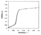
このゼオライトの25℃における吸着等温線を図1に示す。図1からこのゼオライトは相対蒸気圧0.07〜0.10において急激に水蒸気を吸着しており、相対蒸気圧範囲0.05〜0.20の吸着量変化量は0.25g/gであることがわかる。
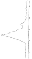
このゼオライトの29Si−MAS−NMRスペクトル測定チャートを図2に示す。29Si−MAS−NMRスペクトルにおいて、−70ppm〜−123ppmの信号強度の積分強度面積に対して、−108ppm〜−123ppmの信号強度の積分強度面積は9.2%であり、−70ppm〜−92ppmの信号強度の積分強度面積は52.6%であった。
【0053】
実施例2
SAPO−34(ケイ素0.03、アルミニウム0.52、リン0.45(モル比)、UOP LLC製)の水蒸気の吸着等温線(25℃)を図3に示す。図3から相対蒸気圧0.07〜0.10において急激に水蒸気を吸着しており、相対蒸気圧範囲0.05〜0.20の吸着量変化量は0.25g/gであることがわかる。
【0054】
尚、SAPO−34はCHA型シリコアルミノフォスフェートであり、CHA型のフレームワーク密度は14.6T/1,000Å3、細孔径は3.8Åである。
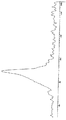
又、SAPO−34(UOP LLC製)の29Si−MAS−NMRチャートを図4に示す。スペクトル測定チャートから、該スペクトルにおいて、−70ppm〜−123ppmの信号強度の積分強度面積に対して、−108ppm〜−123ppmの信号強度の積分強度面積は0.6%であり、−70ppm〜−92ppmの信号強度の積分強度面積は85.9%であった。
【0055】
実施例3
水128gにアルミニウムイソプロポキシド72gを加えて攪拌した後、85%リン酸38.76gを加えて1時間攪拌した。この溶液にfumedシリカ(アエロジル200)1.2gを加えた後さらに35%テトラエチルアンモニウムヒドロキシド(TEAOH)水溶液89.3gを加え、3時間攪拌した。この混合物をテフロン(登録商標)内筒入りの500ccステンレス製オートクレーブに仕込み、185℃で60時間100rpmで攪拌させながら反応させた。反応後、冷却し、遠心分離で生成物を分離、水洗し、120℃で乾燥させた。これを空気気流下550℃6時間焼成して、ゼオライトを得た。
【0056】
粉末XRDで測定した結果、CHA型シリコアルミノフォスフェート(フレームワーク密度=14.6T/1,000Å3)であった。また、試料を塩酸水溶液で加熱溶解させ、ICP分析を行ったところ、骨格構造のアルミニウムとリンとケイ素の合計に対する各成分の構成割合(モル比)は、ケイ素が0.03、アルミニウムが0.50リンが0.47であった。
【0057】
このゼオライトの25℃における吸着等温線を図5に示す。図5からこのゼオライトも実施例1のゼオライトと同様の吸着等温線を示し、相対蒸気圧0.07〜0.10において急激に水蒸気を吸着しており、相対蒸気圧範囲0.05〜0.20の吸着量変化量は0.23g/gであった。
実施例4
水180gに85%リン酸87.1gを加え、これに擬ベーマイト(25%水含有、コンデア製)57.2gをゆっくりと加え、2時間撹拌した。これをA液とした。A液とは別にfumedシリカ(アエロジル200)5.04g、モルホリン36.6g、水240gを混合した液を作り、これをA液にゆっくりと加えた。さらにトリエチルアミン46.6gを加え、これを3時間撹拌した。この時のゲルの組成は以下の通りである。
【0058】
Al2 O3 /0.9P2 O5 /0.2SiO2 /モルホリン/1.1トリエチルアミン/60H2 O
こうして得られた混合物をフッ素樹脂内筒の入った1lのステンレス製オートクレーブに仕込み、100rpmで撹拌しながら190℃で12時間反応させた後さらに200℃に昇温して24時間反応させた。反応後冷却して、デカンテーションにより上澄みを除いて沈殿物を回収した。こうして得られた沈殿物を水で洗浄した後濾別し、120℃で乾燥した。これを空気気流下560℃で6時間焼成してゼオライトを得た。このゼオライトの粉末XRDを測定したところ、CHA構造(フレームワーク密度=14.6T/1,000Å3 )であった。試料を塩酸水溶液で加熱溶解させ、ICP分析により求めたところ、骨格構造のアルミニウムとリンとケイ素の合計に対する各成分の構成割合(モル比)は、元素分析の結果ケイ素が0.07、アルミニウムが0.486、リンが0.444であった。
【0059】
このゼオライトの25℃における吸着等温線を図12に示す。相対蒸気圧範囲0.05〜0.20の吸着量変化は0.19g/gであった。
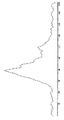
このゼオライトを実施例1と同じ条件で29Si−MAS−NMRを測定した。その結果を図10に示す。このスペクトルにおいて、−70ppmから−123ppmの信号強度の積分面積に対して、−108ppmから−123ppmの信号強度の積分強度面積は0.6%、−70ppmから−92ppmの信号強度の積分強度面積は73.5%であった。
【0060】
実施例5
水128gにアルミニウムイソプロポキシド72gを加えて撹拌した後、85%リン酸39gを加えて1時間撹拌した。この溶液にfumedシリカ(アエロジル200)1.2gを加えた後さらに35%TEAOH(テトラエチルアンモニウムヒドロキシド)水溶液89gを加え、4時間撹拌した。この時のゲルの組成は以下の通りである。
【0061】
Al2 O3 /0.95P2 O5 /0.1SiO2 /1.1TEAOH/57H2 O
この混合物をフッ素樹脂内筒入りの500ccステンレス製オートクレーブに仕込み、100rpmで撹拌しながら180℃で48時間反応させた。反応後、冷却し、遠心分離で生成物を分離、水洗し、120℃で乾燥させた。これを空気気流下550℃6時間焼成して、ゼオライトを得た。このゼオライトをXRDで測定した結果CHA構造であった。また、骨格構造のアルミニウムとリンとケイ素の合計に対する各成分の構成割合(モル比)は、元素分析の結果ケイ素が0.033、アルミニウムが0.491、リンが0.476であった。これの25℃の吸着等温線を図13に示す。相対蒸気圧範囲0.05〜0.20の吸着量変化は0.24g/gであった。
【0062】
実施例6
水16gにアルミニウムイソプロポキシド9gを加えて撹拌した後、85%リン酸5.1gを加えて1時間撹拌した。この溶液にfumedシリカ(アエロジル200)0.45gを加えた後さらに35%TEAOH(テトラエチルアンモニウムヒドロキシド)水溶液9.3gを加え、2時間撹拌した。この時のゲルの組成は以下の通りである。
【0063】
Al2 O3 /1P2 O5 /0.3SiO2 /1TEAOH/57H2 O
この混合物をフッ素樹脂内筒入りの200ccステンレス製オートクレーブに仕込み、静置の状態で200℃で48時間反応させた。反応後、冷却し、遠心分離で生成物を分離、水洗し、120℃で乾燥させた。これを空気気流下550℃6時間焼成して、ゼオライトを得た。このゼオライトをXRDで測定した結果CHA構造であった。また、骨格構造のアルミニウムとリンとケイ素の合計に対する各成分の構成割合(モル比)は、元素分析の結果ケイ素が0.067、アルミニウムが0.482、リンが0.45であった。これの25℃の吸着等温線を図14に示す。相対蒸気圧範囲0.05〜0.20の吸着量変化は、0.20であった。
【0064】
比較例1
水173.4gに85%リン酸115.3gを加え、さらに擬ベーマイト(25%水含有。コンデア社製)68gをゆっくり加えて3時間撹拌した。これにfumedシリカ30gを加え、モルホリン87.2gおよび水242.3gを加えて4.5時間撹拌した。これを一晩室温で静置状態で熟成し、テフロン(登録商標)内筒入りの誘導撹拌式1Lのステンレス製オートクレーブに仕込み、60rpmで撹拌し、200℃で24時間反応させた。反応後冷却して、デカンテーションにより上澄みを除いて沈殿物を回収した。こうして得られた沈殿物を水洗、濾別し、120℃で乾燥させた。これを空気気流下550℃で焼成してゼオライトを得た。このゼオライトのXRDを測定したところ、CHA型であった。また、試料を塩酸水溶液で加熱溶解させ、ICP分析を行ったところ、骨格構造のアルミニウムとリンとケイ素の合計に対する各成分の構成割合(モル比)はケイ素が0.12、アルミニウムが0.49、リンが0.39であった。
【0065】
このゼオライトの25℃における吸着等温線を図6に示す。図6から、このゼオライトは相対蒸気圧がきわめて低い吸着開始状態から急激に水蒸気を吸着しており、相対蒸気圧範囲0.05から0.20の吸着量変化量は0.1g/g以下しかない事がわかる。これから比較的低温の熱源を駆動源とする吸着ヒートポンプ用吸着材としては不適である。
【0066】
これを同条件でSi−MAS−NMR測定した結果を図7に示す。29Si−MAS−NMRスペクトルにおいて、−70ppm〜−123ppmの信号強度の積分面積に対して、−108ppm〜−123ppmの信号強度の積分強度面積は13.0%であった。また、−70ppm〜−92ppmの信号強度の積分値は51.6%であった。この様に−110ppm付近のピーク強度が大きいとCHA型シリコアルミノフォスフェートでも吸着材として適さない事が判る。
【0067】
【発明の効果】
吸着ヒートポンプ用の吸着材としては、一般的にシリカゲルと低シリカアルミナ比のゼオライトが用いられてきた。しかし、従来吸着ヒートポンプに利用されてきた吸着材は、比較的低温の熱源を吸着ヒートポンプの駆動源として利用するには吸脱着能力が不十分であった。
【0068】
例えば、吸着ヒートポンプ用のゼオライトの代表例として13Xの水蒸気吸着等温線を考えると、相対蒸気圧0.05以下で急激に吸着され、0.05より高い相対蒸気圧域ではゼオライトの水蒸気吸着量は変化しない。吸着剤を再生する際には、周囲の気体の相対湿度を低下させて一度吸着した水分を脱着して除くが、ゼオライト13Xに吸着された水を脱着するには相対蒸気圧を下げる必要があるため、150℃〜200℃の熱源が必要であると言われている。一般にゼオライトは水の吸着能力に優れるが、一度吸着すると吸着質が脱着しづらく、再生に高温の熱源が必要という欠点がある。
【0069】
また最近では界面活性剤のミセル構造を鋳型として合成したメソポーラスモレキュラーシーブ(FSM−10など)(特開平9−178292号)や通称AlPO−5等の多孔質リン酸アルミニウム系モレキュラーシーブ(特開平11−197439号)などのゼオライトも検討されている。メソポーラスモレキュラーシーブ(FSM−10)は相対蒸気圧0.20と0.35の範囲で吸着量差は0.25g/gと大きく、有望な素材である(特開平9−178292号:図14のグラフ4;FSM−10)。しかし、本発明の吸着ヒートポンプの運転操作の一例である相対蒸気圧0.05〜0.30の範囲では吸着量が小さい。その中でも吸着量変化が大きいのは相対蒸気圧0.15〜0.30の範囲であるが、この時の吸着量差は0.08g/gであり、吸着ヒートポンプの性能は劣らざるを得ない。また、繰り返し使用すると構造が崩れ、吸着材としての機能が低下することが指摘されており、耐久性が課題となっている。
【0070】
例えば、図8に示す多孔質リン酸アルミニウム系モレキュラーシーブのAFI型(フレームワーク密度=17.5T/1,000Å3)ゼオライトであるALPO−5の吸着等温線(Colloid Polym Sci 277, p83〜88(1999), Fig.1(吸着温度30℃)より引用)の吸着等温線によると、ALPO−5は相対蒸気圧0.25〜0.40の範囲で吸着量が急激に上昇し、相対蒸気圧0.05〜0.3の範囲で吸脱着させることは可能であるが、相対蒸気圧0.15〜0.30の範囲での吸着量変化は0.14g/gであった。
【0071】
吸着ヒートポンプに適した吸着材として知られているシリカゲルA型(富士シリシア化学(株))を吸着等温線測定装置(ベルソーブ18:日本ベル(株))により測定した、吸着温度25℃の水蒸気の吸着等温線を図9に示す。なお、この測定は図1の実施例1と同じ条件で行った。図9のシリカゲルA型の吸着等温線によると、シリカゲルA型は、相対水蒸気圧0〜0.7の範囲で相対水蒸気圧とほぼ比例した吸着量が得られる。しかし、メソポーラスモレキュラーシーブや多孔質リン酸アルミニウム系モレキュラーシーブと同じ相対蒸気圧0.15〜0.30の範囲ではA型シリカゲルは0.08g/gしか吸着量が変化しない。シリカゲルを吸着材として使用した吸着ヒートポンプが商品化されているが、この吸着量差が小さいことが原因で装置が大きくならざるを得ない。
【0072】
本発明の、骨格構造にアルミニウム、リンおよびケイ素を含み、29Si−MAS−NMRスペクトルにおける−108ppm〜−123ppmの信号強度の積分強度面積が−70ppm〜−123ppmの信号強度の積分強度面積に対して10%以下である水蒸気吸着材によれば、吸着材の吸脱着による水分吸着量の差が大きく、低温度で吸着材の再生(脱着)が可能になるため、従来に比べて低温の熱源を利用して、効率よく吸着ヒートポンプを駆動することができる。すなわち、本発明の吸着材によれば、100℃以下の比較的低温の熱源で駆動する吸着ヒートポンプを提供できる。
【図面の簡単な説明】
【図1】実施例1の水蒸気吸着等温線である。
【図2】実施例1の29Si−MAS−NMRスペクトル測定チャートである
。
【図3】実施例2の水蒸気吸着等温線である。
【図4】実施例2の29Si−MAS−NMRスペクトル測定チャートである
。
【図5】実施例3の水蒸気吸着等温線である。
【図6】比較例1の水蒸気吸着等温線である。
【図7】比較例1の29Si−MAS−NMRスペクトル測定チャートである
。
【図8】A型シリカゲルの水蒸気吸着等温線である。
【図9】ALPO−5の水蒸気吸着等温線である。
【図10】本発明の吸着ヒートポンプの一例の概念図である。
【図11】実施例4の29Si−MAS−NMRスペクトル測定チャートである。
【図12】実施例4の水蒸気吸着等温線である。
【図13】実施例5の水蒸気吸着等温線である。
【図14】実施例6の水蒸気吸着等温線である。
【符号の説明】
1 吸着塔
2 吸着塔
3 吸着質配管
4 蒸発器
5 凝縮器
11 熱媒配管
111 冷却水入口
112 冷却水出口
113 温水入口
114 温水出口
115 切り替えバルブ
116 切り替えバルブ
21 熱媒配管
211 冷却水入口
212 冷却水出口
213 温水入口
214 温水出口
215 切り替えバルブ
216 切り替えバルブ
30 吸着質配管
31 制御バルブ
32 制御バルブ
33 制御バルブ
34 制御バルブ
300 室内機
301 ポンプ
41 冷水配管(入口)
42 冷水配管(出口)
51 冷却水配管(入口)
52 冷却水配管(出口)[0001]
BACKGROUND OF THE INVENTION
The present invention relates to a water vapor adsorbent for adsorption heat pump containing zeolite, an adsorption heat pump using the water vapor adsorbent, a vehicle air conditioner using the heat pump, and the like.
[0002]
[Prior art]
Adsorbents are used in adsorption heat pumps and dehumidifying air conditioners, but in order to regenerate the adsorbate, for example, adsorbent that has adsorbed water, the adsorbent is heated to desorb the adsorbate, and the dried adsorbent is removed from the adsorbent. It is cooled to the temperature used for adsorption and used again for adsorbate adsorption.
[0003]
In order to desorb the adsorbate from the adsorbent, an adsorption heat pump using exhaust heat or heat at a relatively high temperature (120 ° C. or higher) has already been put into practical use. However, since the heat obtained by cooling water or solar heat from cogeneration equipment, fuel cells, automobile engines, etc. is relatively low at 100 ° C or less, it cannot be used as a driving heat source for adsorption heat pumps that are currently in practical use. Therefore, effective utilization of low-temperature exhaust heat of 100 ° C. or lower, and further 60 ° C. to 80 ° C. has been demanded.
[0004]
Although the operation principle of the adsorption heat pump is the same, the adsorption characteristics required for the adsorbent differ greatly depending on the available heat source temperature. For example, the exhaust heat temperature of a gas engine cogeneration or a polymer electrolyte fuel cell to be used as a heat source on the high temperature side is 60 ° C. to 80 ° C., and the temperature of cooling water for an automobile engine is 85 ° C. to 90 ° C. .
[0005]
And the temperature of the heat source for cooling the dried adsorbent also varies depending on the installation location of the apparatus. For example, in the case of an automobile, the temperature is obtained by a radiator, and in a building or a house, the temperature is such as a water cooling tower or river water. That is, the operating temperature range of the adsorption heat pump is 25 ° C to 35 ° C on the low temperature side when installed in a building or the like, 60 ° C to 80 ° C on the high temperature side, 30 ° C to 40 ° C on the low temperature side when installed on an automobile, etc. The high temperature side is about 85 ° C to 90 ° C. In order to effectively utilize such low-temperature exhaust heat, an apparatus that can be driven even if the temperature difference between the low-temperature side heat source and the high-temperature side heat source is small is desired.
[0006]
In order for the device to operate sufficiently even at a relatively high temperature around the adsorbent, it is necessary to adsorb the adsorbate at a low relative vapor pressure, and to reduce the size of the device by using a small amount of adsorbent. Needs a large amount of adsorption / desorption of the adsorbent. In order to use a low-temperature heat source for adsorbate desorption (regeneration of adsorbent), the desorption temperature needs to be low. That is, as an adsorbent used in an adsorption heat pump or a dehumidifying air conditioner, (1) an adsorbate adsorbs at a low relative vapor pressure, (2) a large amount of adsorption / desorption, and (3) an adsorbent that adsorbs an adsorbate at a high relative vapor pressure. Is desired.
[0007]
[Problems to be solved by the invention]
An object of the present invention is to provide an adsorbent that adsorbs and desorbs water vapor in a low relative vapor pressure region, and an efficient adsorption heat pump using the adsorbent.
[0008]
[Means for Solving the Problems]
As a result of intensive studies to solve the above-mentioned problems, the present inventors have found a water vapor adsorbent suitable for an apparatus using adsorption / desorption of adsorbate such as an adsorption heat pump as a drive source of the apparatus.
That is, the gist of the present invention is an adsorbent, an adsorption / desorption portion having an adsorbent for adsorbing / desorbing the adsorbate, an evaporation portion for evaporating the adsorbate connected to the adsorption / desorption portion, and an adsorption / desorption portion connected to the adsorption / desorption portion. An operation method of an adsorption heat pump comprising a condensing part for condensing adsorbate, wherein the adsorbent is a water vapor adsorbent containing zeolite, and the zeolite contains aluminum, phosphorus and silicon in the skeleton structure, And the integrated intensity area of the signal intensity of -108 ppm to -123 ppm in the 29 Si-MAS-NMR spectrum of the zeolite is 10% or less with respect to the integrated intensity area of the signal intensity of -70 ppm to -123 ppm, The method of operating an adsorption heat pump, wherein the adsorbate is desorbed from the heat medium and the temperature of the heating medium heated when the adsorbent is regenerated is 100 ° C. or less Exist.
Other aspects of the present invention include an adsorbate, an adsorption / desorption portion having an adsorbent for adsorbing / desorbing the adsorbate, an evaporation portion for evaporating the adsorbate connected to the adsorption / desorption portion, and a connection to the adsorption / desorption portion. An operation method of an adsorption heat pump comprising a condensing unit for condensing the adsorbate formed, wherein the adsorbent is a water vapor adsorbent containing zeolite, and the zeolite contains aluminum, phosphorus and silicon in the skeleton structure. And the integrated intensity area of the signal intensity of -108 ppm to -123 ppm in the 29 Si-MAS-NMR spectrum of the zeolite is 10% or less with respect to the integrated intensity area of the signal intensity of -70 ppm to -123 ppm, The adsorbate is desorbed from the material to regenerate the adsorbent, and the temperature of the heating medium to be heated is 60 to 95 ° C., and the temperature of the condensing part is 30 to 40 ° C. This is the operation method of the adsorption heat pump.
Still another gist of the present invention is that an adsorbate, an adsorption / desorption portion having an adsorbent for adsorbing and desorbing the adsorbate, an evaporation portion for evaporating the adsorbate connected to the adsorption / desorption portion, and the adsorption / desorption portion a suction pump having a condenser portion for performing condensation of concatenated adsorbate, the temperature of the heat medium for heating the pre-Symbol adsorbent when reproducing the adsorbent to desorb the
0.001 ≦ x ≦ 0.3 (1)
(In the formula, x represents the molar ratio of silicon to the total of aluminum, phosphorus and silicon in the skeleton structure)
0.3 ≦ y ≦ 0.6 (2)
(Wherein y represents the molar ratio of aluminum to the total of aluminum, phosphorus and silicon in the skeleton structure)
0.3 ≦ z ≦ 0.6 (3)
(Wherein z represents the molar ratio of phosphorus to the total of aluminum, phosphorus and silicon in the skeleton structure)
When the relative vapor pressure in the water vapor adsorption isotherm in the range of relative vapor pressure of 0.05 to 0.30 is changed by 0.15, the change in the adsorption amount of water is 0.18 g / g. those having more relative vapor pressure range, lies in the adsorption heat pump, characterized in that.
Still another subject matter of the present invention lies in a vehicle air conditioner characterized in that the adsorption heat pump is used for air conditioning in a vehicle compartment.
[0009]
DETAILED DESCRIPTION OF THE INVENTION
First, the operation principle of the adsorption heat pump of the present invention will be described.
The operating vapor pressure range of the adsorption heat pump is determined by the desorption side relative vapor pressure φ1 and the adsorption side relative vapor pressure φ2 obtained from the high temperature heat source temperature High, the low temperature heat source temperature Tlow1, the low temperature heat source temperature Tlow2, and the cold heat generation temperature Tcool.
[0010]
φ1 and φ2 are the following formulas (a) and (b)
Desorption side relative vapor pressure φ1 = equilibrium vapor pressure (Tlow1) / equilibrium vapor pressure (High) (a)
Adsorption side relative vapor pressure φ2 = equilibrium vapor pressure (Tcool) / equilibrium vapor pressure (Tlow2) (b)
The relative vapor pressure range that can be operated is between φ1 and φ2.
[0011]
Here, the high temperature heat source temperature High is the temperature of the heat medium heated when desorbing the adsorbate from the adsorbent to regenerate the adsorbent, the low temperature heat source temperature Tlow1 is the temperature of the adsorbate in the condensing part, and the low temperature heat source temperature Tlow2. Means the temperature of the heat medium to be cooled when the adsorbent after regeneration is used for adsorption, and the cold generation temperature Tcool means the temperature of the adsorbate in the evaporation section, that is, the temperature of the generated cold. The equilibrium vapor pressure can be determined from the temperature using the equilibrium vapor pressure curve of the adsorbate.
[0012]
Hereinafter, the operating vapor pressure range when the adsorbate is water will be exemplified. When the high temperature heat source temperature High is 80 ° C., the low temperature heat
[0013]
From the above, when the adsorption heat pump is driven using the exhaust heat of the gas engine cogeneration, the polymer electrolyte fuel cell or the automobile engine, the operation relative water vapor pressure range is φ1 to φ2 = 0.05 to 0.30. If limited, it is considered that φ1 to φ2 = 0.06 to 0.29. That is, when the adsorbent is regenerated by lowering the relative water vapor pressure by heating, desorption must be completed when the relative water vapor pressure is in the range of 0.05, preferably 0.06 or more. On the other hand, in terms of adsorption, a sufficient adsorption amount must be obtained within a relative vapor pressure of 0.30, preferably 0.29 or less. That is, a material having a large change in adsorption amount within this operating humidity range is preferable. Therefore, the lower limit of the relative vapor pressure is 0.05, preferably 0.06, the upper limit is 0.30, preferably 0.29, that is, the relative vapor pressure range is selected from a combination of these lower and upper limits. Preferably, a material whose adsorption amount greatly changes in the range of 0.05 to 0.30, more preferably 0.06 to 0.29 is appropriate.
[0014]
For example, it is assumed that a cooling capacity of 3.0 kW (= 10,800 kJ / hr) is obtained by an adsorption heat pump. Here, 3.0 kW is the cooling capacity of an air conditioner used for a general automobile air conditioner. It is considered that the capacity of the adsorption heat pump is desirably at least 15 liters or less based on engine room surveys of various vehicles.
[0015]
Next, the adsorbent weight that can be filled in a volume of 15 liters or less is determined.
The parts to be mounted in the engine room include an adsorption tower body, an evaporator, a condenser, and control valves. It is necessary to make the assembly in which these are integrally formed into a capacity of 15 liters or less. In our study, it is considered that the size of the evaporator, condenser and valves can be formed with about 4.5 liters. Therefore, the capacity of the adsorption tower body is approximately 10.5 liters or less. Since the adsorbent packing ratio and the adsorbent bulk density in the adsorption tower are usually about 30% and about 0.6 kg / liter, respectively, the adsorbent weight (W) that can be packed is 10.5 × 30% × 0.6. = 1.89kg.
[0016]
Next, characteristics required for the adsorbent will be described.
The cooling capacity R in the adsorption heat pump is expressed by the following formula A.
R = (W · ΔQ · η C · ΔH / τ) · η h (Formula A)
Here, W is the weight of the adsorbent packed in one adsorption tower (one side), ΔQ is the equilibrium adsorption amount amplitude in the conditions of adsorption and desorption, and the adsorption amount difference (Q2-Q1), and η C is the equilibrium adsorption. Adsorption amplitude efficiency indicating the ratio of the actual adsorption amplitude within the switching time with respect to the amplitude ΔQ, ΔH is the latent heat of vaporization of water, τ is the switching time between the adsorption process and the desorption process, η h is the hot water in the adsorbent and heat exchanger The heat mass efficiency which considered the heat mass loss by changing the temperature between temperature and cooling water temperature is shown.
[0017]
As described above, R is 3 kW, and W is 1.89 kg / 2 = 0.95 kg. From our past studies, τ is appropriately about 60 seconds, and ΔH, η C , and η h are about 2500 kJ / kg, 0.6, and 0.85, respectively (Equation A). When ΔQ is obtained,
ΔQ = R / W / η C / ΔH ・ τ / η h = 3.0 / 0.95 / 0.6 / 2500 ・ 60 / 0.85 = 0.149kg / kg
It becomes. That is, as an adsorbent used for the adsorption heat pump for automobiles, ΔQ is preferably 0.15 g / g or more, 0.18 g / g or more, and more preferably 0.20 g / g or more.
[0018]
As described above, the description has been made on the assumption that it is applied to an automobile, but it goes without saying that it can be sufficiently applied to other uses such as stationary use as long as the above characteristics are satisfied.
Adsorption heat pumps use the ability of adsorbents to adsorb and desorb adsorbates as a drive source. In the adsorption heat pump, water, ethanol, acetone, or the like can be used as the adsorbate, but water is most preferable because of its safety, price, and latent heat of vaporization. The adsorbate is adsorbed on the adsorbent as vapor, and the adsorbent is preferably a material having a large change in adsorption amount in a narrow relative vapor pressure range. When the change in adsorption amount is large in a narrow relative vapor pressure range, the amount of adsorbent required to obtain the same adsorption amount under the same conditions is reduced, and the adsorption heat pump is driven even if the temperature difference between the cooling heat source and the heating heat source is small. Because it can.
[0019]
The water vapor adsorbing material of the present invention is a water vapor adsorbing material containing zeolite, which has one feature. Water vapor adsorbents are used in dehumidifiers, desiccant air conditioners, humidity control building materials, etc. that directly adsorb water vapor in the atmosphere, and are used as adsorbents in environments where only water vapor exists in a vacuum, such as adsorption heat pumps. .
[0020]
The zeolite contained in the water vapor adsorbent of the present invention (hereinafter sometimes referred to as “the zeolite of the present invention”) will be described in detail below.
The zeolite of the present invention contains aluminum, phosphorus and silicon in the framework structure.
The integrated intensity area of the signal intensity of −108 ppm to −123 ppm in the 29 Si-MAS-NMR spectrum of the zeolite of the present invention is preferably 10% or less with respect to the integrated intensity area of the signal intensity of −70 ppm to −123 ppm, preferably Is 9.5% or less, more preferably 9% or less of zeolite. If the intensity area ratio is too large, the adsorption / desorption characteristics in the low relative vapor pressure region are inferior.
[0021]
Further, the integrated intensity area of the signal intensity of -70 ppm to -92 ppm in the 29 Si-MAS-NMR spectrum is 25% or more with respect to the integrated intensity area of the signal intensity of -70 ppm to -123 ppm, preferably 50%. That's it.
The 29 Si-MAS-NMR spectrum in the present invention was obtained by measuring a sample in which tetramethylsilane was used as a standard substance and a sample was stored in a water desiccator at room temperature for a whole day and saturated with water, under the following conditions. is there.
Device: Chemical CMX-400
Probe: 7.5 mm MAS probe resonance frequency: 79.445 MHz
Pulse width: 5.0 microseconds Pulse series: Single pulse waiting time: 60 seconds Rotation speed: 4000 rps
The 29 Si-MAS-NMR spectrum of zeolite gives information on the bonding state of Si in the zeolite, and the Si bonding state can be known from the position and distribution of the peak.
[0022]
The zeolite of the present invention contains aluminum, phosphorus and silicon, and the silicon atom in the zeolite is present in units of SiO 2 . Here, in the spectrum of 29 Si-MAS-NMR, the peak in the vicinity of −90 ppm is that in which a silicon atom is bonded to an atom other than four silicon atoms via an oxygen atom. On the other hand, the peak in the vicinity of −110 ppm is one in which a silicon atom is bonded to four silicon atoms via oxygen atoms. That is, a zeolite having a high peak intensity around −110 ppm means that silicon atoms gather together and the dispersibility of silicon atoms in the zeolite is low.
[0023]
It is considered that the dispersibility of Si affects the adsorption characteristics of the zeolite, and as will be described later, zeolite having a high dispersibility of silicon atoms exhibits performance particularly suitable for an adsorbent of an adsorption heat pump.
In the zeolite of the present invention, the abundance ratio of aluminum, phosphorus and silicon atoms is represented by the following formulas (1), (2) and (3).
0.001 ≦ x ≦ 0.3 (1)
(Wherein x represents the molar ratio of silicon to the total of aluminum, phosphorus and silicon in the skeleton structure)
0.3 ≦ y ≦ 0.6 (2)
(Wherein y represents the molar ratio of aluminum to the total of aluminum, phosphorus and silicon in the skeleton structure)
0.3 ≦ z ≦ 0.6 (3)
(Wherein z represents the molar ratio of phosphorus to the total of aluminum, phosphorus and silicon in the skeleton structure)
Those satisfying the above are preferable.
Among the abundance ratios of the atoms in the zeolite, the abundance ratio (x) of silicon in the formula (1) is preferably 0.25 or less, and more preferably 0.2 or less.
[0024]
Further, as described above, a silicon atom having high dispersibility is considered preferable in terms of the adsorptive performance of the present invention, and in order to obtain such dispersibility, the silicon abundance ratio (x) is , 0.09 or less tends to be advantageous, 0.085 or less is more preferable, and 0.08 or less is particularly preferable. Further, the silicon presence ratio (x) is preferably 0.003 or more, more preferably 0.005 or more, and particularly preferably 0.01 or more.
[0025]
Moreover, as long as it is in the range of silicon, aluminum, and phosphorus having the above composition, other elements may be included in the skeleton. Examples of other elements include lithium, magnesium, titanium, zirconium, vanadium, chromium, manganese, iron, cobalt, nickel, palladium, copper, zinc, gallium, germanium, arsenic, tin, calcium, and boron. The zeolite includes those having a cation species exchangeable with other cations. In this case, the cations include protons, alkaline elements such as Li, Na, and K, alkaline earth elements such as Mg and Ca, Examples include rare earth elements such as La and Ce, and transition metal elements such as Fe, Co, and Ni. Protons, alkali elements, and alkaline earth elements are preferable.
[0026]
The above atomic ratio can be determined by elemental analysis. Elemental analysis values are obtained by ICP analysis after dissolving a sample with a hydrochloric acid aqueous solution.
The zeolite of the present invention may be a natural zeolite or an artificial zeolite. For example, an artificial zeolite includes aluminosilicates, aluminophosphates, and the like according to International Zeolite Association (IZA) regulations.
[0027]
The structure of the zeolite of the present invention is represented by a code defined by International Zeolite Association (IZA), and is usually AEI, AFR, AFS, AFT, AFT, AFX, AHT, CHA, DFO, ERI, FAU, GIS, LEV, LTA, VFI. AEI, GIS, CHA, VFI, AFS, LTA, FAU, and AFY are preferable, and CHA is most preferable.
[0028]
The structure of the zeolite is determined by measuring the XRD pattern by powder XRD (powder X-ray diffraction) and comparing it with the XRD pattern described in Collection Of Simulated XRD Powder Patterns For Zeolites (1996, ELSEVIER).
Also, the relationship between the structure and the framework density is described in IZA's Atlas Of Zeolite Structure Types (1996, ELSEVIER), and the framework density can be known from the structure.
[0029]
The framework density of the zeolite of the present invention is usually from 10.0 T / 1000 A 3 to 16.0 T / 1000 A 3 , preferably from 10.0 T / 1000 A 3 to 15.0 T / 1000 A 3 .
As for the zeolite of the present invention, when the relative vapor pressure changes by 0.15 in the normal vapor pressure isotherm of 0.05 to 0.30 in the water vapor adsorption isotherm, the water adsorption amount changes by 0.18 g / g or more. Zeolite is preferable, and zeolite changing by 0.20 g / g or more is more preferable. Further, a zeolite in which the amount of water adsorbed changes by 0.18 g / g or more within a relative vapor pressure of 0.05 to 0.20 is more preferable, and a zeolite in which 0.20 g / g or more changes is most preferable. In the water vapor adsorption isotherm, the adsorption amount at a relative vapor pressure of 0.05 is usually 0.15 g / g or less, preferably 0.12 g / g or less, more preferably 0.10 g / g or less, particularly 0.07 g. / G or less is preferable, and 0.05 g / g or less is most preferable.
[0030]
In addition, the measurement of the water vapor adsorption isotherm of the water vapor adsorbent in the present invention is performed under the following conditions.
Adsorption isotherm measuring device: Bersorb 18 (Nippon Bell Co., Ltd.)
Air hot bath temperature: 50 ° C
Adsorption temperature: 25 ° C
Initial introduction pressure: 3.0 torr
Introduced pressure setting points: 0
Saturated vapor pressure: 23.76 mmHg
Equilibrium time: 500 seconds Pretreatment: 200 ° C., evacuation for 5 hours The production method of the zeolite of the present invention is not particularly limited as long as it has the above-mentioned properties, but for example, Japanese Patent Publication No. 4-37007 and Japanese Patent Publication No. 5-21844 It can be produced by the following method according to the methods described in Japanese Patent Publication No. 5-51533, US Pat. No. 4,440,871 and the like.
[0031]
First, an aqueous gel is prepared by mixing an aluminum source, a silica source, a phosphoric acid source and a template.
As the aluminum source, pseudoboehmite, aluminum isopropoxide, aluminum hydroxide, alumina sol, sodium aluminate and the like are used.
As the silica source, fumed silica, silica sol, colloidal silica, water glass, ethyl silicate, methyl silicate and the like are used.
[0032]
Phosphoric acid is used as the phosphoric acid source. Aluminum phosphate can also be used.
As templates, quaternary ammonium salts such as tetramethylammonium, tetraethylammonium, tetrapropylammonium, tetrabutylammonium, morpholine, di-n-propylamine, tri-n-propylamine, tri-n-isopropylamine, triethylamine, Triethanolamine, piperidine, cyclohexylamine, 2-methylpyridine, N, N-dimethylbenzylamine, N, N-diethylethanolamine, dicyclohexylamine, N, N-dimethylethanolamine, choline, N, N′-
[0033]
The order of mixing the aluminum source, the silica source, the phosphoric acid source and the template varies depending on the conditions. Usually, however, the phosphoric acid source and the aluminum source are first mixed, and then the silica source and the template are mixed. The composition of the aqueous gel is expressed by the molar ratio of the oxide, and is generally 0.02 <SiO 2 / P 2 O 5 <20, 0.02 <SiO 2 / Al 2 O 3 <20, preferably 0 .04 <SiO 2 / P 2 O 5 <10, 0.04 <SiO 2 / Al 2 O 3 <10. The pH of the aqueous gel is 5 to 10, preferably 6 to 9. In addition, in order for the silicon abundance ratio (x) to be 0.09 or less as one method for obtaining a silicon atom having good dispersibility, the composition of the aqueous gel is expressed by the molar ratio of the oxide, 0.02 <SiO 2 / Al 2 O 3 <0.5 is preferable, more preferably 0.02 <SiO 2 / Al 2 O 3 <0.4, and particularly preferably 0.02 <SiO 2 / Al 2 O. 3 <0.35. The ratio of P 2 O 5 / Al 2 O 3 is 0.6 or more and 1.3 or less, preferably 0.7 or more and 1.2 or less, more preferably 0.8 or more and 1.1 or less. The proportion of water is usually 3 or more, preferably 5 or more, more preferably 10 or more, and usually 200 or less, preferably 150 or less, more preferably 120 or less, in molar ratio with respect to Al 2 O 3 . is there.
[0034]
In addition, you may coexist a component other than the above suitably in aqueous gel. Examples of such components include hydrophilic organic solvents such as hydroxides and salts of alkali metals and alkaline earth metals, and alcohols.
The prepared aqueous gel is put into a pressure vessel, and hydrothermal synthesis is performed by maintaining a predetermined temperature under stirring or standing under self-generated pressure or gas pressurization that does not inhibit crystallization.
[0035]
The conditions for hydrothermal synthesis are usually 100 ° C to 300 ° C, preferably 120 ° C to 250 ° C. The reaction time is usually 5 hours to 30 days, preferably 10 hours to 15 days.
After hydrothermal synthesis, the product is separated, washed with water, dried, and the organic matter contained is removed by a method such as calcination to obtain zeolite.
[0036]
As a particularly preferred zeolite of the present invention, for example, silicoaluminophosphate having a CHA structure can be mentioned. From the standpoint of adsorption characteristics, the pore diameter of zeolite is preferably 3 to 10 mm.
Since the zeolite contained in the water vapor adsorbent of the present invention exhibits a large change in adsorption amount with a small relative vapor pressure, zeolite alone can be used as an excellent water vapor adsorbent. When used as an adsorbent for an adsorption heat pump, the zeolite can be processed into a water vapor adsorbent having characteristics such as predetermined strength, particle diameter, and shape.
[0037]
When processing zeolite for use as a water vapor adsorbent, it is necessary to take care not to lower the adsorption performance of the zeolite, but in general, molding is performed using an inorganic binder such as alumina or silica.
Further, in order to give the water vapor adsorbing material the desired water vapor adsorbing properties, silica gel, mesoporous silica, alumina, activated carbon, clay and the like may be included in the water vapor adsorbing material in addition to the zeolite of the present invention. However, in order to obtain good adsorption characteristics at a low relative vapor pressure, the ratio of the zeolite to the water vapor adsorbent of the present invention is usually 60% by weight or more, preferably 70% by weight or more, more preferably 80% by weight or more, From the standpoint of adsorption characteristics, it is most preferable to use only zeolite as a water vapor adsorbent.
[0038]
When the water vapor adsorbing material of the present invention is used for water vapor adsorption, a large amount of water vapor is adsorbed in a low relative vapor pressure region, water vapor can be adsorbed efficiently, and it can be used in an adsorption / desorption portion of an adsorption heat pump.
The water vapor adsorbing material of the present invention has an adsorption amount that changes more at a low relative vapor pressure compared to conventional silica gel and zeolite. And an evaporating part for evaporating the adsorbate connected to the adsorption / desorption part and a condensing part for condensing the adsorbate connected to the adsorption / desorption part.
[0039]
In addition, since a large change in the adsorption amount can be obtained with a narrow range of relative vapor pressure changes, among adsorption heat pumps, an adsorption heat pump that requires a smaller apparatus and a limited amount of adsorbent, such as a vehicle air conditioner, is used. It can be suitably used.
The operating conditions of the adsorption heat pump using the water vapor adsorbent of the present invention may be selected as appropriate so that the performance of the adsorption heat pump is manifested as desired, but the equilibrium vapor pressure of the cooling water temperature is used to desorb the adsorbate from the adsorbent. The desorption side relative vapor pressure φ1 determined by dividing by the equilibrium vapor pressure of the heat source temperature to be used is 0.05 or more, and the equilibrium vapor pressure of the generated cold temperature is divided by the equilibrium vapor pressure of the cooling water temperature. It is also possible to select severe conditions such that the determined adsorption-side relative vapor pressure φ2 is 0.30 or less.
[0040]
Hereinafter, although the effect | action of the adsorption heat pump of this invention is demonstrated concretely, the adsorption heat pump of this invention is not limited by this.
An example of a conceptual diagram of the adsorption heat pump of the present invention is shown in FIG. The adsorption heat pump shown in FIG. 10 includes an adsorbent capable of adsorbing and desorbing adsorbate, and
[0041]
As shown in FIG. 10, the adsorption towers 1 and 2 filled with the adsorbent are connected to each other by an
The evaporator 4 and the
[0042]
A
[0043]
The hot water is introduced from the
[0044]
The operation method of the adsorption heat pump will be described with reference to FIG. In the first stroke, the
[0045]
When the
[0046]
The
[0047]
In the next second step, the evaporators are similarly switched by switching the
[0048]
Here, the operation method in the case where two adsorption towers are installed has been described. However, by properly desorbing the adsorbate adsorbed by the adsorbent, one of the adsorption towers can maintain a state in which the adsorbate can be adsorbed. If possible, any number of adsorption towers may be installed.
The adsorbent for the adsorption heat pump of the present invention changes the adsorption amount more at a low relative vapor pressure. Therefore, various conventionally known air conditioners having an adsorbate adsorption / desorption part, specifically, dehumidification air conditioners. There is a possibility of application as an adsorbent (adsorbent for a desiccant air conditioner) of a desorption part of a so-called desiccant air conditioner. In that case, it is applicable by changing the adsorbent in the known desiccant air conditioner to the adsorbent of the present invention.
[0049]
【Example】
Example 1
In accordance with the method described in Japanese Patent Publication No. 4-37007, a CHA-type silicoaluminophosphate was produced by the following method.
To 18 g of water, 15.4 g of 85% phosphoric acid and 9.2 g of pseudoboehmite (containing 25% water, manufactured by Condea) were slowly added and stirred. Further, 10 g of water was added and stirred for 1 hour. Separately from the A liquid, a liquid in which 4.1 g of fumed silica (Aerosil 200), 11.6 g of morpholine, and 15 g of water were mixed was slowly added to the A liquid. Further, 24 g of water was added thereto and stirred for 3 hours.
[0050]
The obtained mixture was charged into a 200 cc stainless steel autoclave containing a Teflon (registered trademark) inner cylinder and allowed to react at 200 ° C. for 24 hours. After the reaction, the reaction mixture was cooled and the supernatant was removed by decantation to collect a precipitate. The obtained precipitate was washed with water three times, filtered, and dried at 120 ° C. This was calcined at 550 ° C. for 6 hours under an air stream to obtain zeolite.
[0051]
As a result of measurement of powder XRD, this zeolite was of the CHA type (framework density = 14.6 T / 1,000 Å 3 ) silicoaluminophosphate. The framework density was determined from the structure with reference to IZA's Atlas Of Zeolite Structure Types (1996, ELSEVIER). Further, when the sample was heated and dissolved in an aqueous hydrochloric acid solution and ICP analysis was performed, the composition ratio (molar ratio) of each component with respect to the total of aluminum, phosphorus and silicon in the skeleton structure was 0.13 for silicon and 0.2 for aluminum. 49 phosphorus was 0.38.
[0052]
The adsorption isotherm of this zeolite at 25 ° C. is shown in FIG. From FIG. 1, this zeolite adsorbs water vapor abruptly at a relative vapor pressure of 0.07 to 0.10, and the amount of adsorption change in the relative vapor pressure range of 0.05 to 0.20 is 0.25 g / g. I understand that.
A 29 Si-MAS-NMR spectrum measurement chart of this zeolite is shown in FIG. In the 29 Si- MAS- NMR spectrum, the integrated intensity area of the signal intensity of -108 ppm to -123 ppm is 9.2% with respect to the integrated intensity area of the signal intensity of -70 ppm to -123 ppm, and -70 ppm to -92 ppm. The integrated intensity area of the signal intensity was 52.6%.
[0053]
Example 2
The water vapor adsorption isotherm (25 ° C.) of SAPO-34 (silicon 0.03, aluminum 0.52, phosphorus 0.45 (molar ratio), manufactured by UOP LLC) is shown in FIG. It can be seen from FIG. 3 that water vapor is rapidly adsorbed at a relative vapor pressure of 0.07 to 0.10, and the amount of change in the adsorption amount in the relative vapor pressure range of 0.05 to 0.20 is 0.25 g / g. .
[0054]
SAPO-34 is a CHA-type silicoaluminophosphate, and the CHA-type framework density is 14.6 T / 1,000Å3 and the pore diameter is 3.8Å.
FIG. 4 shows a 29 Si-MAS-NMR chart of SAPO-34 (manufactured by UOP LLC). From the spectrum measurement chart, in the spectrum, the integrated intensity area of the signal intensity of −108 ppm to −123 ppm is 0.6% with respect to the integrated intensity area of the signal intensity of −70 ppm to −123 ppm, and −70 ppm to −92 ppm. The integrated intensity area of the signal intensity was 85.9%.
[0055]
Example 3
After adding 72 g of aluminum isopropoxide to 128 g of water and stirring, 38.76 g of 85% phosphoric acid was added and stirred for 1 hour. After adding 1.2 g of fumed silica (Aerosil 200) to this solution, 89.3 g of 35% tetraethylammonium hydroxide (TEAOH) aqueous solution was further added and stirred for 3 hours. This mixture was charged into a 500 cc stainless steel autoclave containing a Teflon (registered trademark) inner cylinder, and reacted at 185 ° C. for 60 hours with stirring at 100 rpm. After the reaction, the mixture was cooled, and the product was separated by centrifugation, washed with water, and dried at 120 ° C. This was calcined in an air stream at 550 ° C. for 6 hours to obtain zeolite.
[0056]
As a result of measurement by powder XRD, it was a CHA type silicoaluminophosphate (framework density = 14.6 T / 1,000 3 ). Further, when the sample was heated and dissolved in an aqueous hydrochloric acid solution and subjected to ICP analysis, the composition ratio (molar ratio) of each component to the total of aluminum, phosphorus and silicon in the skeleton structure was 0.03 for silicon and 0.2 for aluminum. 50 phosphorus was 0.47.
[0057]
The adsorption isotherm of this zeolite at 25 ° C. is shown in FIG. FIG. 5 shows that this zeolite also exhibits the same adsorption isotherm as that of the zeolite of Example 1, and rapidly adsorbs water vapor at a relative vapor pressure of 0.07 to 0.10, and a relative vapor pressure range of 0.05 to 0.00. The amount of change in the adsorption amount of 20 was 0.23 g / g.
Example 4
87.1 g of 85% phosphoric acid was added to 180 g of water, and 57.2 g of pseudoboehmite (containing 25% water, manufactured by Condea) was slowly added thereto and stirred for 2 hours. This was designated as liquid A. Separately from the liquid A, 5.04 g of fumed silica (Aerosil 200), 36.6 g of morpholine, and 240 g of water were prepared, and this was slowly added to the liquid A. Further, 46.6 g of triethylamine was added, and this was stirred for 3 hours. The composition of the gel at this time is as follows.
[0058]
Al 2 O 3 /0.9P 2 O 5 /0.2SiO 2 /morpholine/1.1 triethylamine / 60H 2 O
The mixture thus obtained was charged into a 1 liter stainless steel autoclave containing a fluororesin inner cylinder, reacted at 190 ° C. for 12 hours with stirring at 100 rpm, further heated to 200 ° C. and reacted for 24 hours. After the reaction, the reaction mixture was cooled and the supernatant was removed by decantation to collect a precipitate. The precipitate thus obtained was washed with water, filtered, and dried at 120 ° C. This was calcined at 560 ° C. for 6 hours under an air stream to obtain zeolite. When the powder XRD of this zeolite was measured, it was a CHA structure (framework density = 14.6T / 1,0001 , 3 ). When the sample was heated and dissolved in an aqueous hydrochloric acid solution and obtained by ICP analysis, the composition ratio (molar ratio) of each component to the total of aluminum, phosphorus, and silicon in the skeleton structure was 0.07 for silicon and aluminum for aluminum as a result of elemental analysis. It was 0.486 and phosphorus was 0.444.
[0059]
The adsorption isotherm of this zeolite at 25 ° C. is shown in FIG. The amount of adsorption change in the relative vapor pressure range of 0.05 to 0.20 was 0.19 g / g.
29 Si-MAS-NMR of this zeolite was measured under the same conditions as in Example 1. The result is shown in FIG. In this spectrum, with respect to the integrated area of the signal intensity from -70 ppm to -123 ppm, the integrated intensity area of the signal intensity from -108 ppm to -123 ppm is 0.6%, and the integrated intensity area of the signal intensity from -70 ppm to -92 ppm is It was 73.5%.
[0060]
Example 5
After 72 g of aluminum isopropoxide was added to 128 g of water and stirred, 39 g of 85% phosphoric acid was added and stirred for 1 hour. After adding 1.2 g of fumed silica (Aerosil 200) to this solution, 89 g of 35% TEAOH (tetraethylammonium hydroxide) aqueous solution was further added and stirred for 4 hours. The composition of the gel at this time is as follows.
[0061]
Al 2 O 3 /0.95P 2 O 5 /0.1SiO 2 /1.1TEAOH/57H 2 O
This mixture was charged into a 500 cc stainless steel autoclave containing a fluororesin inner cylinder and reacted at 180 ° C. for 48 hours while stirring at 100 rpm. After the reaction, the mixture was cooled, and the product was separated by centrifugation, washed with water, and dried at 120 ° C. This was calcined in an air stream at 550 ° C. for 6 hours to obtain zeolite. This zeolite was measured by XRD and found to have a CHA structure. In addition, as a result of elemental analysis, the composition ratio (molar ratio) of each component with respect to the total of aluminum, phosphorus, and silicon in the skeleton structure was 0.033 for silicon, 0.491 for aluminum, and 0.476 for phosphorus. The adsorption isotherm at 25 ° C. is shown in FIG. The adsorption amount change in the relative vapor pressure range of 0.05 to 0.20 was 0.24 g / g.
[0062]
Example 6
After 9 g of aluminum isopropoxide was added to 16 g of water and stirred, 5.1 g of 85% phosphoric acid was added and stirred for 1 hour. To this solution, 0.45 g of fumed silica (Aerosil 200) was added, and then 9.3 g of 35% TEAOH (tetraethylammonium hydroxide) aqueous solution was added and stirred for 2 hours. The composition of the gel at this time is as follows.
[0063]
Al 2 O 3 / 1P 2 O 5 /0.3
This mixture was charged into a 200 cc stainless steel autoclave containing a fluororesin inner cylinder and allowed to react at 200 ° C. for 48 hours in a stationary state. After the reaction, the mixture was cooled, and the product was separated by centrifugation, washed with water, and dried at 120 ° C. This was calcined in an air stream at 550 ° C. for 6 hours to obtain zeolite. This zeolite was measured by XRD and found to have a CHA structure. As a result of elemental analysis, the composition ratio (molar ratio) of each component with respect to the total of aluminum, phosphorus, and silicon in the skeleton structure was 0.067 for silicon, 0.482 for aluminum, and 0.45 for phosphorus. The adsorption isotherm at 25 ° C. is shown in FIG. The amount of adsorption change in the relative vapor pressure range of 0.05 to 0.20 was 0.20.
[0064]
Comparative Example 1
115.3 g of 85% phosphoric acid was added to 173.4 g of water, and further 68 g of pseudoboehmite (containing 25% water; manufactured by Condea) was slowly added and stirred for 3 hours. To this, 30 g of fumed silica was added, 87.2 g of morpholine and 242.3 g of water were added, and the mixture was stirred for 4.5 hours. This was aged overnight at room temperature, charged in a 1 L stainless steel autoclave with an induction stirring type containing a Teflon (registered trademark) inner cylinder, stirred at 60 rpm, and reacted at 200 ° C. for 24 hours. After the reaction, the reaction mixture was cooled and the supernatant was removed by decantation to collect a precipitate. The precipitate thus obtained was washed with water, filtered off and dried at 120 ° C. This was calcined at 550 ° C. in an air stream to obtain zeolite. When the XRD of this zeolite was measured, it was a CHA type. Further, when the sample was heated and dissolved in an aqueous hydrochloric acid solution and analyzed by ICP, the composition ratio (molar ratio) of each component to the total of aluminum, phosphorus and silicon in the skeleton structure was 0.12 for silicon and 0.49 for aluminum. The phosphorus was 0.39.
[0065]
The adsorption isotherm of this zeolite at 25 ° C. is shown in FIG. From FIG. 6, this zeolite adsorbs water vapor rapidly from the adsorption start state where the relative vapor pressure is very low, and the amount of change in the adsorption amount in the relative vapor pressure range of 0.05 to 0.20 is only 0.1 g / g or less. I understand that there is not. Therefore, it is not suitable as an adsorbent for an adsorption heat pump using a relatively low-temperature heat source as a drive source.
[0066]
The result of Si-MAS-NMR measurement under the same conditions is shown in FIG. In the 29 Si-MAS-NMR spectrum, the integrated intensity area of the signal intensity of -108 ppm to -123 ppm was 13.0% with respect to the integrated area of the signal intensity of -70 ppm to -123 ppm. Moreover, the integrated value of the signal intensity of −70 ppm to −92 ppm was 51.6%. Thus, it can be seen that if the peak intensity near -110 ppm is large, even CHA type silicoaluminophosphate is not suitable as an adsorbent.
[0067]
【The invention's effect】
As adsorbents for adsorption heat pumps, silica gel and zeolite with a low silica alumina ratio have been generally used. However, adsorbents that have been used in conventional adsorption heat pumps have insufficient adsorption / desorption capability to use a relatively low-temperature heat source as a drive source for the adsorption heat pump.
[0068]
For example, when a 13X water vapor adsorption isotherm is considered as a representative example of a zeolite for an adsorption heat pump, the water vapor adsorption amount of zeolite is rapidly adsorbed at a relative vapor pressure of 0.05 or less, and in a relative vapor pressure region higher than 0.05, It does not change. When regenerating the adsorbent, the relative humidity of the surrounding gas is lowered to remove the water once adsorbed, but it is necessary to lower the relative vapor pressure to desorb the water adsorbed on the zeolite 13X. Therefore, it is said that a heat source of 150 ° C. to 200 ° C. is necessary. In general, zeolite is excellent in water adsorption ability, but once adsorbed, adsorbate is difficult to desorb and has a drawback that a high-temperature heat source is required for regeneration.
[0069]
Recently, mesoporous molecular sieves (such as FSM-10) (JP 9-178292 A) synthesized using a micelle structure of a surfactant as a template (Japanese Patent Laid-Open No. 9-178292) and porous aluminum phosphate molecular sieves (commonly known as AlPO-5) -197439) and the like are also being studied. Mesoporous molecular sieve (FSM-10) is a promising material with a relative vapor pressure in the range of 0.20 and 0.35 and a large adsorption amount difference of 0.25 g / g (Japanese Patent Laid-Open No. 9-178292: FIG. 14). Graph 4; FSM-10). However, the amount of adsorption is small in the range of relative vapor pressure of 0.05 to 0.30, which is an example of the operation of the adsorption heat pump of the present invention. Among them, the adsorption amount change is large in the range of the relative vapor pressure of 0.15 to 0.30, but the adsorption amount difference at this time is 0.08 g / g, and the performance of the adsorption heat pump has to be inferior. . In addition, it has been pointed out that the structure collapses and the function as an adsorbent decreases when used repeatedly, and durability is an issue.
[0070]
For example, adsorption isotherm (Colloid Poly Sci 277, p83-88) of ALPO-5, which is an AFI type (framework density = 17.5T / 1,0001,3) zeolite of the porous aluminum phosphate molecular sieve shown in FIG. 1999), Fig. 1 (
[0071]
A silica gel type A (Fuji Silysia Chemical Co., Ltd.), known as an adsorbent suitable for an adsorption heat pump, was measured with an adsorption isotherm (Belsorb 18: Nippon Bell Co., Ltd.). The adsorption isotherm is shown in FIG. In addition, this measurement was performed on the same conditions as Example 1 of FIG. According to the adsorption isotherm of the silica gel A type in FIG. 9, the silica gel A type can obtain an adsorption amount substantially proportional to the relative water vapor pressure in the range of the relative water vapor pressure of 0 to 0.7. However, in the same relative vapor pressure range of 0.15 to 0.30 as that of mesoporous molecular sieve and porous aluminum phosphate molecular sieve, the amount of adsorption of A-type silica gel is only 0.08 g / g. Adsorption heat pumps using silica gel as an adsorbent have been commercialized, but the apparatus must be large due to the small difference in adsorption amount.
[0072]
In the present invention, the skeleton structure contains aluminum, phosphorus and silicon, and the integrated intensity area of the signal intensity of -108 ppm to -123 ppm in the 29 Si-MAS-NMR spectrum is relative to the integrated intensity area of the signal intensity of -70 ppm to -123 ppm. With a water vapor adsorbent of less than 10%, the difference in moisture adsorption due to adsorption / desorption of the adsorbent is large, and the adsorbent can be regenerated (desorbed) at a low temperature. Can be used to efficiently drive the adsorption heat pump. That is, according to the adsorbent of the present invention, an adsorption heat pump that is driven by a relatively low-temperature heat source of 100 ° C. or less can be provided.
[Brief description of the drawings]
1 is a water vapor adsorption isotherm of Example 1. FIG.
2 is a 29 Si-MAS-NMR spectrum measurement chart of Example 1. FIG.
3 is a water vapor adsorption isotherm of Example 2. FIG.
4 is a 29 Si-MAS-NMR spectrum measurement chart of Example 2. FIG.
5 is a water vapor adsorption isotherm of Example 3. FIG.
6 is a water vapor adsorption isotherm of Comparative Example 1. FIG.
7 is a 29 Si-MAS-NMR spectrum measurement chart of Comparative Example 1. FIG.
FIG. 8 is a water vapor adsorption isotherm of A-type silica gel.
FIG. 9 is a water vapor adsorption isotherm of ALPO-5.
FIG. 10 is a conceptual diagram of an example of an adsorption heat pump according to the present invention.
11 is a 29 Si-MAS-NMR spectrum measurement chart of Example 4. FIG.
12 is a water vapor adsorption isotherm of Example 4. FIG.
13 is a water vapor adsorption isotherm of Example 5. FIG.
14 is a water vapor adsorption isotherm of Example 6. FIG.
[Explanation of symbols]
DESCRIPTION OF
42 Cold water piping (exit)
51 Cooling water piping (inlet)
52 Cooling water piping (exit)
Claims (15)
前記吸着材が、ゼオライトを含む水蒸気吸着材であって、該ゼオライトが骨格構造にアルミニウム、リンおよびケイ素を含み、かつ、該ゼオライトの29Si−MAS−NMRスペクトルにおける−108ppm〜−123ppmの信号強度の積分強度面積が−70ppm〜−123ppmの信号強度の積分強度面積に対して10%以下であり、
前記吸着材から前記吸着質を脱着して前記吸着材を再生する際に加熱する熱媒の温度が100℃以下であることを特徴とする吸着ヒートポンプの運転方法。An adsorbent, an adsorption / desorption part having an adsorbent for adsorbing and desorbing the adsorbate, an evaporation part for evaporating the adsorbate connected to the adsorption / desorption part, and condensing the adsorbate connected to the adsorption / desorption part An operation method of an adsorption heat pump including a condensing unit,
The adsorbent is a water vapor adsorbent containing zeolite, the zeolite contains aluminum, phosphorus and silicon in the framework structure, and a signal intensity of −108 ppm to −123 ppm in the 29 Si-MAS-NMR spectrum of the zeolite Is 10% or less with respect to the integrated intensity area of the signal intensity of -70 ppm to -123 ppm,
A method for operating an adsorption heat pump, wherein a temperature of a heating medium heated when the adsorbate is desorbed from the adsorbent to regenerate the adsorbent is 100 ° C or less.
前記吸着材が、ゼオライトを含む水蒸気吸着材であって、該ゼオライトが骨格構造にアルミニウム、リンおよびケイ素を含み、かつ、該ゼオライトの29Si−MAS−NMRスペクトルにおける−108ppm〜−123ppmの信号強度の積分強度面積が−70ppm〜−123ppmの信号強度の積分強度面積に対して10%以下であり、
前記吸着材から前記吸着質を脱着して前記吸着材を再生する際に加熱する熱媒の温度が60〜95℃であり、前記凝縮部の温度が30〜40℃であることを特徴とする吸着ヒートポンプの運転方法。An adsorbent, an adsorption / desorption part having an adsorbent for adsorbing and desorbing the adsorbate, an evaporation part for evaporating the adsorbate connected to the adsorption / desorption part, and condensing the adsorbate connected to the adsorption / desorption part An operation method of an adsorption heat pump including a condensing unit,
The adsorbent is a water vapor adsorbent containing zeolite, the zeolite contains aluminum, phosphorus and silicon in the framework structure, and a signal intensity of −108 ppm to −123 ppm in the 29 Si-MAS-NMR spectrum of the zeolite Is 10% or less with respect to the integrated intensity area of the signal intensity of -70 ppm to -123 ppm,
The adsorbate is desorbed from the adsorbent and the temperature of the heating medium heated when regenerating the adsorbent is 60 to 95 ° C, and the temperature of the condensing part is 30 to 40 ° C. Operation method of adsorption heat pump.
0.001≦x≦0.3 ・・・(1)
(式中、xは骨格構造のアルミニウム、リン、およびケイ素の合計に対するケイ素のモル比を示す)
0.3≦y≦0.6 ・・・(2)
(式中、yは骨格構造のアルミニウム、リン、およびケイ素の合計に対するアルミニウムのモル比を示す)
0.3≦z≦0.6 ・・・(3)
(式中、zは骨格構造のアルミニウム、リン、およびケイ素の合計に対するリンのモル比を示す)
を満足するものである請求項1〜3のいずれか1項に記載の吸着ヒートポンプの運転方法。The abundance ratio of aluminum, phosphorus and silicon atoms contained in the framework structure of the zeolite is represented by the following formulas (1), (2) and (3)
0.001 ≦ x ≦ 0.3 (1)
(In the formula, x represents the molar ratio of silicon to the total of aluminum, phosphorus and silicon in the skeleton structure)
0.3 ≦ y ≦ 0.6 (2)
(Wherein y represents the molar ratio of aluminum to the total of aluminum, phosphorus and silicon in the skeleton structure)
0.3 ≦ z ≦ 0.6 (3)
(Wherein z represents the molar ratio of phosphorus to the total of aluminum, phosphorus and silicon in the skeleton structure)
The operation method of the adsorption heat pump according to any one of claims 1 to 3.
前記吸着材から前記吸着質を脱着して前記吸着材を再生する際に加熱する熱媒の温度を100℃以下とし、
前記吸着材が、ゼオライトを含む水蒸気吸着材であって、該ゼオライトが骨格構造にアルミニウム、リンおよびケイ素を含み、かつ、前記ゼオライトの29Si−MAS−NMRスペクトルにおける−108ppm〜−123ppmの信号強度の積分強度面積が−70ppm〜−123ppmの信号強度の積分強度面積に対して10%以下であり、
前記ゼオライトの骨格構造に含まれるアルミニウム、リンおよびケイ素の原子の存在割合が下記式(1)、(2)および(3)
0.001≦x≦0.3 ・・・(1)
(式中、xは骨格構造のアルミニウム、リン、およびケイ素の合計に対するケイ素のモル比を示す)
0.3≦y≦0.6 ・・・(2)
(式中、yは骨格構造のアルミニウム、リン、およびケイ素の合計に対するアルミニウムのモル比を示す)
0.3≦z≦0.6 ・・・(3)
(式中、zは骨格構造のアルミニウム、リン、およびケイ素の合計に対するリンのモル比を示す)
を満足し、
前記ゼオライトが、水蒸気吸着等温線において相対蒸気圧0.05以上、0.30以下の範囲で相対蒸気圧が0.15変化したときに水の吸着量変化が0.18g/g以上の相対蒸気圧域を有するものである、ことを特徴とする吸着ヒートポンプ。 Adsorbate desorption unit having an adsorbent to desorb the adsorbate, the evaporation unit for the evaporation of the consolidated been adsorbate suction desorption unit, and linked condensation of adsorbate suction desorption unit An adsorption heat pump with a condensing part to perform,
The temperature of the heat medium for heating the pre-Symbol adsorbent when reproducing the adsorbent to desorb the adsorbate and 100 ° C. or less,
The adsorbent is a water vapor adsorbent containing zeolite, the zeolite contains aluminum, phosphorus and silicon in the framework structure, and a signal intensity of −108 ppm to −123 ppm in the 29 Si-MAS-NMR spectrum of the zeolite Is 10% or less with respect to the integrated intensity area of the signal intensity of -70 ppm to -123 ppm,
The abundance ratio of aluminum, phosphorus and silicon atoms contained in the framework structure of the zeolite is represented by the following formulas (1), (2) and (3)
0.001 ≦ x ≦ 0.3 (1)
(In the formula, x represents the molar ratio of silicon to the total of aluminum, phosphorus and silicon in the skeleton structure)
0.3 ≦ y ≦ 0.6 (2)
(Wherein y represents the molar ratio of aluminum to the total of aluminum, phosphorus and silicon in the skeleton structure)
0.3 ≦ z ≦ 0.6 (3)
(Wherein z represents the molar ratio of phosphorus to the total of aluminum, phosphorus and silicon in the skeleton structure)
Satisfied,
When the zeolite has a relative vapor pressure of 0.15 or more in the range of relative vapor pressure of 0.05 or more and 0.30 or less in the water vapor adsorption isotherm, the relative amount of adsorption of water is 0.18 g / g or more. and it has a pressure range, the adsorption heat pump, characterized in that.
Priority Applications (1)
| Application Number | Priority Date | Filing Date | Title |
|---|---|---|---|
| JP2002175356A JP4249437B2 (en) | 2001-06-25 | 2002-06-17 | Adsorption heat pump, adsorption heat pump operation method, and vehicle air conditioner using adsorption heat pump |
Applications Claiming Priority (7)
| Application Number | Priority Date | Filing Date | Title |
|---|---|---|---|
| JP2001-191893 | 2001-06-25 | ||
| JP2001191893 | 2001-06-25 | ||
| JP2001293990 | 2001-09-26 | ||
| JP2001-293990 | 2001-09-26 | ||
| JP2002-78798 | 2002-03-20 | ||
| JP2002078798 | 2002-03-20 | ||
| JP2002175356A JP4249437B2 (en) | 2001-06-25 | 2002-06-17 | Adsorption heat pump, adsorption heat pump operation method, and vehicle air conditioner using adsorption heat pump |
Related Child Applications (1)
| Application Number | Title | Priority Date | Filing Date |
|---|---|---|---|
| JP2008275311A Division JP4896110B2 (en) | 2001-06-25 | 2008-10-27 | Zeolite and adsorbent |
Publications (3)
| Publication Number | Publication Date |
|---|---|
| JP2003340236A JP2003340236A (en) | 2003-12-02 |
| JP2003340236A5 JP2003340236A5 (en) | 2005-06-23 |
| JP4249437B2 true JP4249437B2 (en) | 2009-04-02 |
Family
ID=29783294
Family Applications (1)
| Application Number | Title | Priority Date | Filing Date |
|---|---|---|---|
| JP2002175356A Expired - Fee Related JP4249437B2 (en) | 2001-06-25 | 2002-06-17 | Adsorption heat pump, adsorption heat pump operation method, and vehicle air conditioner using adsorption heat pump |
Country Status (1)
| Country | Link |
|---|---|
| JP (1) | JP4249437B2 (en) |
Cited By (1)
| Publication number | Priority date | Publication date | Assignee | Title |
|---|---|---|---|---|
| JP2009097856A (en) * | 2001-06-25 | 2009-05-07 | Mitsubishi Chemicals Corp | Adsorption heat pump, operation method for adsorption heat pump and vehicle air conditioner using adsorption heat pump |
Families Citing this family (5)
| Publication number | Priority date | Publication date | Assignee | Title |
|---|---|---|---|---|
| JP5061581B2 (en) * | 2005-11-04 | 2012-10-31 | 三菱化学株式会社 | Adsorption element and humidity control air conditioner using the same |
| JP5076143B2 (en) * | 2007-02-21 | 2012-11-21 | 国立大学法人大阪大学 | Apparatus for measuring gas adsorption characteristics of fine pore particles and measuring method thereof |
| JP5730584B2 (en) * | 2009-01-22 | 2015-06-10 | 三菱樹脂株式会社 | Nitrogen oxide purification catalyst and method for producing the same |
| EP2400241A4 (en) | 2009-02-19 | 2014-07-23 | Fujitsu Ltd | Heat pump |
| CN107646086A (en) * | 2015-01-08 | 2018-01-30 | 百瑞空气工程(亚洲)有限公司 | Split type adsorption/absorption refrigeration system |
-
2002
- 2002-06-17 JP JP2002175356A patent/JP4249437B2/en not_active Expired - Fee Related
Cited By (1)
| Publication number | Priority date | Publication date | Assignee | Title |
|---|---|---|---|---|
| JP2009097856A (en) * | 2001-06-25 | 2009-05-07 | Mitsubishi Chemicals Corp | Adsorption heat pump, operation method for adsorption heat pump and vehicle air conditioner using adsorption heat pump |
Also Published As
| Publication number | Publication date |
|---|---|
| JP2003340236A (en) | 2003-12-02 |
Similar Documents
| Publication | Publication Date | Title |
|---|---|---|
| US7497089B2 (en) | Adsorption heat pump and use of adsorbent as adsorbent for adsorption heat pump | |
| US7037360B2 (en) | Adsorbent for heat utilization system, adsorbent for regenerator system, regenerator system comprising the adsorbent, ferroaluminophosphate and method for production thereof | |
| US7422993B2 (en) | Adsorbent for adsorption heat pump, adsorbent for humidity-control air conditioner, adsorption heat pump and humidity-control air conditioner | |
| US7527777B2 (en) | Zeolite, process for producing the same, adsorbent comprising the zeolite, heat utilization system, adsorption heat pump, cold/heat storage system, and air-conditioning apparatus for humidity regulation | |
| JP5161340B2 (en) | Adsorbent for adsorption heat pump and adsorption heat pump using the same | |
| JP4896110B2 (en) | Zeolite and adsorbent | |
| JP3979327B2 (en) | Adsorbent for adsorption heat pump, adsorption heat pump, and operation method of adsorption heat pump | |
| JP4669914B2 (en) | Adsorption heat pump, vehicle air conditioner, dehumidifying air conditioner, and method of using adsorbent | |
| JP2004132690A (en) | Adsorbent for thermal storage system, thermal storage system using it, iron aluminophosphate, and its manufacturing method | |
| US9387457B2 (en) | Water vapor adsorbent for adsorption heat pump, method for producing water vapor adsorbent, and adsorption heat pump including water vapor adsorbent | |
| JP4542738B2 (en) | Adsorption heat pump, adsorption material for adsorption heat pump, and air conditioner for vehicle | |
| JP4249437B2 (en) | Adsorption heat pump, adsorption heat pump operation method, and vehicle air conditioner using adsorption heat pump | |
| CN100416182C (en) | Adsorption heat pump and use of adsorbent as adsorbent for adsoprtion heat pump | |
| JP5261875B2 (en) | Aluminophosphate zeolite adsorbent comprising oxygen 6-membered ring, production method thereof and use thereof | |
| JP2007083236A (en) | Adsorbent material for air humidity conditioner and air humidity conditioner and its operating method | |
| JP4354755B2 (en) | Adsorbent for adsorption heat pump and adsorption heat pump using the same | |
| JP4654582B2 (en) | Adsorption heat pump operation method, adsorption heat pump, humidity control air conditioner operation method, and humidity control air conditioner | |
| JP4112298B2 (en) | Adsorption heat pump | |
| JP2008267802A (en) | Adsorption heat pump, air conditioner for vehicle, adsorption heat pump operating method, adsorbent for adsorption heat pump, and application method of adsorbent |
Legal Events
| Date | Code | Title | Description |
|---|---|---|---|
| RD02 | Notification of acceptance of power of attorney |
Free format text: JAPANESE INTERMEDIATE CODE: A7422 Effective date: 20040830 |
|
| A521 | Written amendment |
Free format text: JAPANESE INTERMEDIATE CODE: A523 Effective date: 20040924 |
|
| A621 | Written request for application examination |
Free format text: JAPANESE INTERMEDIATE CODE: A621 Effective date: 20040924 |
|
| A977 | Report on retrieval |
Free format text: JAPANESE INTERMEDIATE CODE: A971007 Effective date: 20060308 |
|
| A131 | Notification of reasons for refusal |
Free format text: JAPANESE INTERMEDIATE CODE: A131 Effective date: 20060322 |
|
| A521 | Written amendment |
Free format text: JAPANESE INTERMEDIATE CODE: A523 Effective date: 20060519 |
|
| A131 | Notification of reasons for refusal |
Free format text: JAPANESE INTERMEDIATE CODE: A131 Effective date: 20080520 |
|
| A521 | Written amendment |
Free format text: JAPANESE INTERMEDIATE CODE: A523 Effective date: 20080722 |
|
| A02 | Decision of refusal |
Free format text: JAPANESE INTERMEDIATE CODE: A02 Effective date: 20080826 |
|
| A521 | Written amendment |
Free format text: JAPANESE INTERMEDIATE CODE: A523 Effective date: 20080925 |
|
| A911 | Transfer of reconsideration by examiner before appeal (zenchi) |
Free format text: JAPANESE INTERMEDIATE CODE: A911 Effective date: 20081205 |
|
| TRDD | Decision of grant or rejection written | ||
| A01 | Written decision to grant a patent or to grant a registration (utility model) |
Free format text: JAPANESE INTERMEDIATE CODE: A01 Effective date: 20090106 |
|
| A01 | Written decision to grant a patent or to grant a registration (utility model) |
Free format text: JAPANESE INTERMEDIATE CODE: A01 |
|
| A61 | First payment of annual fees (during grant procedure) |
Free format text: JAPANESE INTERMEDIATE CODE: A61 Effective date: 20090115 |
|
| FPAY | Renewal fee payment (event date is renewal date of database) |
Free format text: PAYMENT UNTIL: 20120123 Year of fee payment: 3 |
|
| R150 | Certificate of patent or registration of utility model |
Ref document number: 4249437 Country of ref document: JP Free format text: JAPANESE INTERMEDIATE CODE: R150 Free format text: JAPANESE INTERMEDIATE CODE: R150 |
|
| FPAY | Renewal fee payment (event date is renewal date of database) |
Free format text: PAYMENT UNTIL: 20120123 Year of fee payment: 3 |
|
| S111 | Request for change of ownership or part of ownership |
Free format text: JAPANESE INTERMEDIATE CODE: R313117 |
|
| R350 | Written notification of registration of transfer |
Free format text: JAPANESE INTERMEDIATE CODE: R350 |
|
| FPAY | Renewal fee payment (event date is renewal date of database) |
Free format text: PAYMENT UNTIL: 20130123 Year of fee payment: 4 |
|
| R250 | Receipt of annual fees |
Free format text: JAPANESE INTERMEDIATE CODE: R250 |
|
| FPAY | Renewal fee payment (event date is renewal date of database) |
Free format text: PAYMENT UNTIL: 20130123 Year of fee payment: 4 |
|
| FPAY | Renewal fee payment (event date is renewal date of database) |
Free format text: PAYMENT UNTIL: 20140123 Year of fee payment: 5 |
|
| R250 | Receipt of annual fees |
Free format text: JAPANESE INTERMEDIATE CODE: R250 |
|
| R250 | Receipt of annual fees |
Free format text: JAPANESE INTERMEDIATE CODE: R250 |
|
| R250 | Receipt of annual fees |
Free format text: JAPANESE INTERMEDIATE CODE: R250 |
|
| R250 | Receipt of annual fees |
Free format text: JAPANESE INTERMEDIATE CODE: R250 |
|
| R250 | Receipt of annual fees |
Free format text: JAPANESE INTERMEDIATE CODE: R250 |
|
| S111 | Request for change of ownership or part of ownership |
Free format text: JAPANESE INTERMEDIATE CODE: R313115 |
|
| R350 | Written notification of registration of transfer |
Free format text: JAPANESE INTERMEDIATE CODE: R350 |
|
| R250 | Receipt of annual fees |
Free format text: JAPANESE INTERMEDIATE CODE: R250 |
|
| LAPS | Cancellation because of no payment of annual fees |