JP4112298B2 - Adsorption heat pump - Google Patents
Adsorption heat pump Download PDFInfo
- Publication number
- JP4112298B2 JP4112298B2 JP2002202762A JP2002202762A JP4112298B2 JP 4112298 B2 JP4112298 B2 JP 4112298B2 JP 2002202762 A JP2002202762 A JP 2002202762A JP 2002202762 A JP2002202762 A JP 2002202762A JP 4112298 B2 JP4112298 B2 JP 4112298B2
- Authority
- JP
- Japan
- Prior art keywords
- adsorption
- desorption
- water vapor
- adsorbent
- vapor pressure
- Prior art date
- Legal status (The legal status is an assumption and is not a legal conclusion. Google has not performed a legal analysis and makes no representation as to the accuracy of the status listed.)
- Expired - Fee Related
Links
Images


Classifications
-
- Y—GENERAL TAGGING OF NEW TECHNOLOGICAL DEVELOPMENTS; GENERAL TAGGING OF CROSS-SECTIONAL TECHNOLOGIES SPANNING OVER SEVERAL SECTIONS OF THE IPC; TECHNICAL SUBJECTS COVERED BY FORMER USPC CROSS-REFERENCE ART COLLECTIONS [XRACs] AND DIGESTS
- Y02—TECHNOLOGIES OR APPLICATIONS FOR MITIGATION OR ADAPTATION AGAINST CLIMATE CHANGE
- Y02A—TECHNOLOGIES FOR ADAPTATION TO CLIMATE CHANGE
- Y02A30/00—Adapting or protecting infrastructure or their operation
- Y02A30/27—Relating to heating, ventilation or air conditioning [HVAC] technologies
Description
【0001】
【発明の属する技術分野】
本発明は、特定の吸着材を用いた吸着ヒートポンプに関する。
特に、自動車に搭載するのに適した吸着ヒートポンプに関する。
【0002】
【従来の技術】
吸着ヒートポンプにおいては、吸着質、例えば水を吸着した吸着材を再生するために、吸着材を加熱して吸着質を脱着させ、乾燥した吸着材を吸着質の吸着に使用する温度まで冷却して再度吸着質の吸着に使用する。コジェネレーション機器、燃料電池、自動車エンジンの冷却水や太陽熱などによって得られる100℃以下、更には60℃〜90℃の低温排熱を用いて冷熱を発生させる吸着ヒートポンプが求められている。中でも、排熱が大量に発生する自動車ではその実用化が強く求められている。
【0003】
例えば、自動車など、排熱温度が約85〜95℃、かつ冷却に用いる周囲の温度が約35〜45℃の場合、吸着ヒートポンプが充分に作動するためには、吸着材が吸着質を低相対水蒸気圧で吸脱着する必要があり、また使用する吸着材を少量にして装置を小型化するためには吸脱着量が多い吸着材が必要である。そして吸着質の脱着(吸着材の再生)に低温の熱源を利用するためには脱着温度が低い必要がある。すなわち吸着ヒートポンプに用いる吸着材として(1)吸着質を低い相対水蒸気圧で吸脱着し、(2)吸脱着量が多い吸着材、が望まれている。吸着ヒートポンプに用いる吸着材として、各種の吸着材の使用が検討されているが、種々の問題点があり、上記の様な吸着材は見いだされていない。
【0004】
尚、吸着ヒートポンプ用吸着材の吸着特性の温度依存性が重要であることは既に報告されており(化学工学論文集、第19巻、第6号(1993)、P1165−1170)、大きな温度依存性を示すSG3(富士シリシア社製)と、示さないSG1(同)が報告されている。
また、多孔質リン酸アルミニウム系モレキュラーシーブであるAlPO4−5の吸着性能が温度に依存することが報告されており、具体的には25℃と30℃の吸着性能が示されている(Colloid Polym Sci 277(1999)p83-88)。同様にAlPO4−5の温度依存性が報告されており、20℃、25℃、30℃、35℃、40℃の吸着過程での吸着等温線が記載されている(第16回ゼオライト研究発表会講演予稿集p91;平成12年11月21日、22日)。
しかしながら、従来、脱着等温線については着目されておらず、吸着等温線と脱着等温線の関係、更には吸着等温線及び脱着等温線と相対水蒸気圧と吸着量差については、知られていない。
【0005】
【発明が解決しようとする課題】
本発明は、実用上有効な吸着性能を有する吸着ヒートポンプを提供するものである。
【0006】
【課題を解決するための手段】
本発明者らは、ヒートポンプの吸脱着部の操作温度が吸着質の吸着時と脱着時で異なることに着目し、鋭意検討した結果、(1)吸着操作時の吸脱着部温度における吸着等温線及び、(2)脱着操作時の吸脱着部温度における脱着等温線から求められる特定の吸着量差が、ある範囲にある吸着材を用いたヒートポンプが、実用上有用な吸着性能を有するとの知見を得た。即ち、吸着材には、温度によって吸着等温線が変化しないものと変化するもの(後者の変化するものを温度依存性があると略す)が存在し、ゼオライトやシリカの中には、温度依存性を示さないものが多いが、これまで認識されていなかった特定の温度依存性と吸着量差に着目し、特定の範囲での吸着量差が大きい材を用いることにより、吸着ヒートポンプの容量を小型化し、しかもこれまで車の廃熱等では十分な吸着性能を達し得なかった、比較的低温の熱源で作動する実用的な吸着ヒートポンプを提供できることを見出し本発明に到達した。
即ち、本発明の要旨は、下記のとおりである。
(a)吸着質、(b)吸着質を吸脱着する吸着材を備えた吸脱着部、(c)該吸脱着部に連結された吸着質の蒸発を行う蒸発部、及び(d)該吸脱着部に連結された吸着質の凝縮を行う凝縮部とを備えた吸着ヒートポンプにおいて、
(1)吸着材が骨格構造にアルミニウムとリンとヘテロ原子とを含むゼオライトを含み、
(2)吸着材が、吸脱着部の吸着操作時相対水蒸気圧φ2が0.115以上0.18以下、吸脱着部の脱着操作時相対水蒸気圧φ1が0.1以上0.14以下である領域に、下記式で求められる吸着材の吸着量差が0.15g/g以上となる範囲を有する水蒸気吸着材である、
ことを特徴とする吸着ヒートポンプ。
吸着量差=Q2−Q1
ここで、
Q1=吸脱着部の脱着操作温度(T3)で測定した水蒸気脱着等温線から求めたφ1における吸着量
Q2=吸脱着部の吸着操作温度(T4)で測定した水蒸気吸着等温線から求めたφ2における吸着量
但し、
φ1(吸脱着部の脱着操作時相対水蒸気圧)=凝縮部を冷却する冷媒温度(T2)の平衡水蒸気圧/該吸脱着部を加熱する熱媒温度(T1)での平衡水蒸気圧
φ2(吸脱着部の吸着操作時相対水蒸気圧)=蒸発部で生成される冷熱温度(T0)の平衡水蒸気圧/該吸脱着部を冷却する冷媒温度(T2)の平衡水蒸気圧
(ここで、T0=5〜10℃、T1=T3=90℃、T2=T4=40〜45℃とする)
【0007】
【発明の実施の形態】
以下、本発明について更に詳細に説明する。
<吸着ヒートポンプの構造>
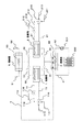
まず、吸着ヒートポンプの構造を図1に示した吸着ヒートポンプを例に説明する。
【0008】
吸着ヒートポンプは、吸着質、吸着質を吸脱着可能な吸着材が充填され、吸着質の吸脱着により発生した熱を熱媒に伝達する吸脱着部(吸着塔1および2、以下、吸脱着部を吸着塔ということがある)と、吸着質の蒸発により得られた冷熱を外部へ取り出す蒸発部(蒸発器4)と、吸着質の凝縮により得られた温熱を外部へ放出する凝縮部(凝縮器5)から主として構成されている。
【0009】
蒸発器4は内部が略真空に保たれた状態で冷媒(本実施形態では、水)が封入されており、この蒸発器4内には室内器300にて室内に吹き出す空気と熱交換した熱媒体(本実施形態では、水にエチレングリコール系の不凍液を混合した流体)と冷媒とを熱交換させるための熱交換器43が設けられている。
吸着塔1および2は、表面に吸着材が接着・充填された熱交換器が収納されており、凝縮器5は吸着塔1,2から脱離した蒸気冷媒(水蒸気)を外気等にて冷却された熱媒体にて冷却凝縮させるための熱交換器53が収納されている。
【0010】
吸着材が充填された吸着塔1及び2は、吸着質配管30により相互に接続され、該吸着質配管30には制御バルブ31〜34が設けられる。尚、吸着質は吸着質配管内で吸着質の蒸気または吸着質の液体と蒸気との混合物として存在する。
吸着質配管30には蒸発器4及び凝縮器5が接続されている。吸着塔1及び2は蒸発器4、凝縮器5の間に並列に接続されており、凝縮器5と蒸発器4の間には、凝縮器にて凝縮された吸着質(好適には、再生された凝縮水)を蒸発器4に戻すための戻し配管3を設ける。なお、符号41は蒸発器4からの冷房出力となる冷水の入口、符号51は凝縮器5に対する冷却水の入口である。符号42及び52はそれぞれ冷水及び冷却水の出口である。また、冷水配管41及び42には、室内空間(空調空間)と熱交換するための室内機300と、冷水を循環するポンプ301が接続されている。
【0011】
吸着塔1には熱媒配管11が、吸着塔2には熱媒配管21がそれぞれ接続され、該熱媒配管11及び21には、それぞれ切り替えバルブ115及び116並びに215及び216が設けてある。また、熱媒配管11及び21はそれぞれ吸着塔1及び2内の吸着材を加熱または冷却するための加熱源または冷却源となる熱媒を流す。熱媒は、特に限定されず、吸着塔内の吸着材を有効に加熱・冷却できればよい。
【0012】
温水は切り替えバルブ(3方弁)115、116、215、及び216の開閉により、入口113及び/又は213より導入され、各吸着塔1及び/又は2を通過し、出口114及び/又は214より導出される。冷却水も同様の切り替えバルブ115、116、215、及び216の開閉により、入口111及び/又は211より導入され、各吸着器1及び/又は2を通過し、出口112及び/又は212より導出される。
【0013】
また蒸発器4と吸着塔1,2とをつなぐ冷媒配管および凝縮器5と吸着塔1,2とをつなぐ冷媒配管のそれぞれには各冷媒配管を開閉する制御弁31〜34が設けられており、これら制御弁31〜34、熱媒体を循環させるポンプ301、および熱媒体流れを制御する3方弁115,116,215,216は電子制御装置(図示せず)により制御されている。
【0014】
また、熱媒配管11及び/又は21には、外気と熱交換可能に配設された室外機、温水を発生する熱源、熱媒を循環するポンプ(いずれも図示せず)が接続されている。熱源としては特に限定されず、例えば自動車エンジン、ガスエンジンやガスタービンなどのコジェネレーション機器および燃料電池などが挙げられ、また、自動車用として用いる時には、自動車エンジン、自動車用燃料電池が好ましい熱源の例として挙げられる。
【0015】
<吸着ヒートポンプ作動概要>
次に、本実施形態に係る空調装置(吸着式ヒートポンプ)の作動の概略を述べる。ポンプ301を作動させて室内器300と蒸発器4との間で熱媒体を循環させることにより、蒸発器4内の液冷媒(好適には、水)を蒸発させて熱媒体を冷却し、室内に吹き出す空気を冷却する。これと同時に、2台の吸着塔1,2のうちいずれか一方の吸着塔が吸着工程となり、他方側の吸着塔が脱離工程(再生工程)となるように制御弁31〜34、および3方弁115,116,215,216を切り替える。
【0016】
具体的に言えば、第1の吸着塔1を吸着工程とし第2の吸着塔2を脱離工程とする場合には、制御弁31を開き、かつ、制御弁33を閉じた状態で、3方弁115を冷却水入口111側に、3方弁116を冷却水出口112側に連通させると同時に、制御弁32を閉じ、かつ、制御弁34を開いた状態で、3方弁215を温水入口213側に、3方弁216を温水出口214側に連通させる。
【0017】
これにより蒸発器4にて蒸発した冷媒(水蒸気)が第1の吸着塔1内に流入してその中の吸着材に吸着されるとともに、この吸着材の温度は入口111からの冷却水により外気温度程度相当に保たれる。
一方第2の吸着塔2には、熱源(車両用に適用した場合は走行用エンジン)にて加熱された温水が温水入口213より供給されるので、第2の吸着塔内の吸着材は吸着工程時に吸着した冷媒を脱離する。そして脱離した冷媒(水蒸気)は凝縮器5にて冷却されて凝縮再生される。
【0018】
所定時間経過後、制御弁31〜34、および3方弁115,116,215,216を切り替えることで、第1の吸着塔1を脱離工程に、第2の吸着塔2を吸着工程に切り替えることができる。このような切り替えを所定時間毎に繰り返すことで、連続的な冷房作動を行うことができる。
<吸着材>
本発明の吸着材は、吸脱着部の吸着操作時相対水蒸気圧φ2が0.115以上0.18以下、吸脱着部の脱着操作時相対水蒸気圧φ1が0.1以上0.14以下である領域に、下記式で求められる吸着材の吸着量差が0.15g/g以上となる範囲を有する水蒸気吸着材である。
【0019】
吸着量差=Q2−Q1
ここで、
Q1=吸脱着部の脱着操作温度(T3)で測定した水蒸気脱着等温線から求めたφ1における吸着量
Q2=吸脱着部の吸着操作温度(T4)で測定した水蒸気吸着等温線から求めたφ2における吸着量
但し、
φ1(吸脱着部の脱着操作時相対水蒸気圧)=凝縮部を冷却する冷媒温度(T2)の平衡水蒸気圧/該吸脱着部を加熱する熱媒温度(T1)での平衡水蒸気圧
φ2(吸脱着部の吸着操作時相対水蒸気圧)=蒸発部で生成される冷熱温度(T0)の平衡水蒸気圧/該吸脱着部を冷却する冷媒温度(T2)の平衡水蒸気圧
(ここで、T0=5〜10℃、T1=T3=90℃、T2=T4=40〜45℃とする)
本発明の吸着材の吸着量差は、上記で特定されるが、より好ましい吸着材は、以下の(A)〜(C)のいずれかの条件で特定される吸着材である。
【0020】
(A)T0が10℃、T2が40℃
(B)T0が5℃、T2が40℃
(C)T0が10℃、T2が45℃
以下、上記の如き吸着材の性能について、図1を参照して説明する。
まず、図1において、制御バルブ31及び34を閉鎖、制御バルブ32及び34を開放のケースで説明する。
【0021】
このケースでは、蒸発器4から供給される水蒸気を吸着して、吸着塔2に充填された吸着材は発熱する。この時、吸着塔2は熱媒パイプ211,21から流通される熱媒(例えば、冷却水)によって冷却、徐熱される。尚、この時の吸着塔2(吸脱着部)を冷却する、パイプ211から供給される熱媒(冷却水)の温度をT2とする。
【0022】
一方、冷熱を生成する目的で蒸発器4の温度は制御される。この時、吸着側相対水蒸気圧φ2は下記式で定義される。
吸着側相対水蒸気圧φ2=平衡水蒸気圧(T0)/平衡水蒸気圧(T2)
平衡水蒸気圧(T0):蒸発器4の温度T0における平衡水蒸気圧
平衡水蒸気圧(T2):吸着塔2の熱媒温度T2の平衡水蒸気圧
一方、同時に吸着塔1は脱着(再生)過程にあり、吸着塔1に充填された吸着材は再生熱源(吸脱着部を加熱する熱媒の温度。この温度をT1とする)によって再生される。凝縮器5は熱媒パイプ51を通じて供給される冷却水で冷却され、水蒸気を凝縮させる。この時、脱着側相対水蒸気圧φ1は下記式で決まる。
【0023】
脱着側相対水蒸気圧φ1=平衡水蒸気圧(T2)/平衡水蒸気圧(T1)
平衡水蒸気圧(T2):凝縮器5の温度の平衡水蒸気圧
(=吸着塔2の熱媒温度T2の平衡水蒸気圧)
平衡水蒸気圧(T1):吸着塔1の再生熱源温度(T1)の平衡水蒸気圧
ここで重要な点は、吸着塔は吸着時の温度と脱着(再生)時の温度が異なることである。従って、本発明においては、吸着量差を脱着時温度における脱着等温線と、吸着時温度における吸着等温線から求めるというものであり、具体的には、下記式により算出する。
【0024】
吸着量差=Q2−Q1
ここで、
Q1=吸脱着部の脱着操作温度(T3)で測定した水蒸気脱着等温線から求めたφ1における吸着量
Q2=吸脱着部の吸着操作温度(T4)で測定した水蒸気吸着等温線から求めたφ2における吸着量
但し、
φ1(吸脱着部の脱着操作時相対水蒸気圧)=凝縮部を冷却する冷媒温度(T2)の平衡水蒸気圧/該吸脱着部を加熱する熱媒温度(T1)での平衡水蒸気圧
φ2(吸脱着部の吸着操作時相対水蒸気圧)=蒸発部で生成される冷熱温度(T0)の平衡水蒸気圧/該吸脱着部を冷却する冷媒温度(T2)の平衡水蒸気圧
(ここで、T0=5〜10℃、T1=T3=90℃、T2=T4=40〜45℃とする)
本発明の吸着材は、上記式で求められる吸着量差が0.15g/g以上であり、好ましくは、0.18g/g以上である。該吸着量差は大きいほど好ましいが、かかる性能を満足する入手可能な材料源から考慮して、通常0.25g/g以下程度である。又、吸着量差は大きいほど好ましいが、通常0.50g/g以下、現実的には0.40g/g以下、更には0.35g/g以下である。
かかる吸着量差が0.15g/g以上であることは、吸着ヒートポンプを自動車適用する場合を想定し、以下の検討に基づき導き出される。
<吸着時温度、脱着時温度>
まず、上述の通り、吸着量は吸着時の温度と脱着時の温度に依存するため、吸着時の温度における吸着等温線と、脱着時温度における脱着等温線を求める。
吸着時、吸着塔は吸着熱による発熱を抑えるために冷却水で冷却されるため、冷却水温度(T2)が、ほぼ吸着時温度(T4)となる。一方、脱着時、吸着塔は脱着熱が必要であり、温水温度(T1)が、脱着時温度(T3)となる。
【0025】
ところで、吸着ヒートポンプの熱媒温度は、(1)温水温度は、エンジン冷却水で得られる温度なのでおよそ90℃、(2)冷却温度は、外気との熱交換で得られる温度なのでおよそ40℃〜45℃、(3)冷風を作るために必要な冷水温度は、およそ5〜10℃、である。即ち、冷水温度は、日本における一般的な車種を前提とした場合でおよそ10℃、高級車ではおよそ5℃が望まれる。また、冷却温度は、日本で40℃程度、外気温の高い地域などではおよそ45℃程度になる。
【0026】
従って、吸着温度(T4)は、およそ40℃〜45℃、脱着温度(T3)はおよそ90℃となる。
本発明では、かかる吸着温度と脱着温度を、吸着材の性能を評価する指標として採用するものであり、吸着温度40℃〜45℃で得られる吸着等温線の少なくともいずれかの吸着等温線と、脱着温度が90℃で得られる脱着等温線から、上記式に従って求められる吸着量差が0.15g/g以上であることを満たすものである。
【0027】
<吸着量差>
上記吸着量差(0.15g/g以上)は、下記に従って求められる。
即ち、吸着ヒートポンプの容量は、種々の車両のエンジンルーム調査から少なくとも15リットル以下であることが望ましいと考えられる。
次に、15リットル以下の容量の中に充填可能な吸着材重量を求める。
【0028】
エンジンルームに載せるべき部品としては吸着塔本体、蒸発器、凝縮器および制御バルブ類がある。これらを概略一体に形成したアッセンブリを15リットル以下の容量にする必要がある。我々の検討では、蒸発器と凝縮器とバルブ類の体格はおよそ4.5リットルで形成できると考えられる。従って吸着塔本体の容量はおよそ10.5リットル以下である。吸着塔内における吸着材の充填率および吸着材のかさ密度は、通常、それぞれ約30%、約0.6kg/リットルであるので、充填可能な吸着材重量(W)は10.5×30%×0.6=1.89kg程度である。
【0029】
次に吸着材に求められる特性について説明する。
一般に車両用エアコンに求められる定常冷房能力はおよそ3kWである。吸着式ヒートポンプでの冷房能力Rは次式Aで表される。
R=(W・ΔQ・ηC・ΔH/τ)・ηh (式A)
ここでWは吸着塔1台(片側)に充填される吸着材重量、ΔQは吸着時と脱離時の条件における平衡吸着量振幅で前記吸着量差(Q2−Q1)、ηCは平衡吸着振幅ΔQに対する切り替え時間内の実際の吸着振幅の割合を示す吸着振幅効率、ΔHは水の蒸発潜熱、τは吸着工程と脱離工程との切り替え時間、ηhは吸着材や熱交換器が温水温度と冷却水温度との間を温度変化することによるヒートマス損失を考慮したヒートマス効率、を示す。
【0030】
Rは前述のように3kW、Wは1.89kg/2=0.95kgである。また我々の過去の検討から、τはおよそ60secが適当であり、ΔH、ηC、ηhの値はそれぞれおよそ2500kJ/kg、0.6、0.85であることが得られているので(式A)からΔQを求めると、
ΔQ = R/W/ηC/ΔH・τ/ηh=3.0/0.95/0.6/2500・60/0.85 = 0.149kg/kg
となる。すなわち自動車用吸着式ヒートポンプに用いる吸着材としては、
ΔQ≧0.15g/gの特性が満足するのが好ましい。
【0031】
以上、自動車への適用を前提に説明したが、上記の特性を満足するものであれば定置用など他の用途にも十分適用可能であることは言うまでもない。
尚、上記本発明の吸着量差は、吸脱着部の吸着操作時相対水蒸気圧φ2が0.115以上0.18以下、吸脱着部の脱着操作時相対水蒸気圧φ1が0.1以上0.14以下の範囲において満足されるものである。この範囲は、吸着ヒートポンプの操作相対水蒸気圧の範囲に概ね相当する。
【0032】
又、φ1及びφ2が0.115以上0.18以下の範囲にあり、φ1がφ2と等しいかそれ以上である領域に、該吸着量差が0.15g/g以上となる範囲を有する場合、吸着ヒートポンプとしてこれまで稼働しないと考えられていた厳しい温度条件でも作動することから有利である。
<吸着材材料>
本発明の特徴の一つである吸着材は、骨格構造にアルミニウムとリンとを含むゼオライトを含有することである。ここでいうゼオライトは天然のゼオライトでも人工のゼオライトでもよく、例えば人工のゼオライトではInternational Zeolite Association (IZA)の規定によるアルミノシリケート類、アルミノフォスフェート類などが含まれる。
【0033】
本発明においては、中でも、親水性の付与のためにアルミニウム、リンの一部をヘテロ原子で置換した、骨格構造にアルミニウムとリンとヘテロ原子とを含むゼオライトを用いる。ヘテロ原子としては、ケイ素、リチウム、マグネシウム、チタン、ジルコニウム、バナジウム、クロム、マンガン、鉄、コバルト、ニッケル、パラジウム、銅、亜鉛、ガリウム、ゲルマニウム、砒素、スズ、カルシウム、または硼素等が挙げられる。
【0034】
ヘテロ原子が、ケイ素、マグネシウム、チタン、ジルコニウム、鉄、コバルト、亜鉛、ガリウム、または硼素であるのが好ましく、特にケイ素であるのが最も好ましく、これは通称SAPOと称されている。これらヘテロ原子は骨格内のアルミニウム、リンと二種類以上置換されていても良い。
本発明で吸着材として用いる好ましいゼオライトとしては、骨格構造にアルミニウムとリンとヘテロ原子を含むゼオライトであって、下記式(1)、(2)および(3)で表される原子の存在割合を有するものが好ましい。
【0035】
0.001≦x≦0.3 ・・・(1)
(式中、xは骨格構造のアルミニウムとリンとヘテロ原子の合計に対するヘテロ原子のモル比を示す)
0.3≦y≦0.6 ・・・(2)
(式中、yは骨格構造のアルミニウムとリンとヘテロ原子の合計に対するアルミニウムのモル比を示す)
0.3≦z≦0.6 ・・・(3)
(式中、zは骨格構造のアルミニウムとリンとヘテロ原子の合計に対するリンのモル比を示す)
そして、上記原子の存在割合のなかで、ヘテロ原子の存在割合が、下記式(4)
0.003≦x≦0.25 ・・・(4)
(式中、xは上記と同義である)
で表されるものが好ましく、下記式(5)
0.005≦x≦0.2 ・・・(5)
(式中、xは上記と同義である)で表されるものが更に好ましい。
【0036】
また、本発明で吸着材として用いるゼオライトは、そのフレームワーク密度が10.0T/1,000Å3以上16.0T/1,000Å3以下であるのが好ましく、更に好ましくは10.0T/1,000Å3以上15.0/1,000Å3以下の範囲のゼオライトである。ここでフレームワーク密度とは、ゼオライトの1,000Å3あたりの酸素以外の骨格を構成する元素の数を意味し、この値はゼオライトの構造により決まるものである。
【0037】
このようなゼオライトの構造としては、IZAが定めるコードで示すと、AFG、MER、LIO、LOS、PHI、BOG、ERI、OFF、PAU、EAB、AFT、LEV、LTN、AEI、AFR、AFX、GIS、KFI、CHA、GME、THO、MEI、VFI、AFS、LTA、FAU、RHO、DFO、EMT、AFY、*BEA等があり、好ましくはAEI、GIS、KFI、CHA、GME、VFI、AFS、LTA、FAU、RHO、EMT、AFY、*BEAが挙げられる。
【0038】
フレームワーク密度は細孔容量と相関があり、一般的に、より小さいフレームワーク密度のゼオライトがより大きい細孔容量を有し、したがって吸着容量が大きくなる。また、現在合成されていないゼオライトも、合成された場合にフレームワーク密度がこの領域内にあれば、本発明においての吸着材として好適に使用できると予想される。
【0039】
例えば、CHA構造のアルミノフォスフェートの場合はケイ素などの原子を骨格内に入れた、SAPO−34、ZYT−6として知られるシリコアルミノフォスフェートを用いる事により所望な吸着性能を持たせる事ができる。なおSAPO−34の合成方法は、米国特許第4440871号公報等に記載されている。ZYT−6の合成方法は、特公平4−37007、特公平5−21844、特公平5−51533号公報等に記載されている。
【0040】
また、ゼオライトがアルミノシリケートの場合は、骨格内のケイ素、アルミニウムの一部(アルミニウムの場合は全部もあり得る)が他の原子、例えば、マグネシウム、チタン、ジルコニウム、バナジウム、クロム、マンガン、鉄、コバルト、亜鉛、ガリウム、スズ、硼素等に置換していてもよい。アルミノシリケートの場合にケイ素とアルミニウム(アルミニウム+ヘテロ原子)のモル比が小さすぎると水蒸気吸着材として一般的に知られている13Xの場合のように、あまりにも低い湿度領域で急激に吸着されてしまい、また大きすぎる場合は疎水的すぎて水をあまり吸着しなくなる。そのため本発明で用いるゼオライトは、ケイ素/アルミニウムのモル比が4以上20以下であるのが好ましく、更に4.5以上18以下が好ましく、特に5以上16以下がさらに好ましい。
【0041】
これらのゼオライトは交換可能なカチオン種を持つものを含むが、その場合のカチオン種としては、プロトン、Li、Naなどのアルカリ元素、Mg、Caなどのアルカリ土類元素、La、Ce等の希土類元素、Fe、Co、Ni等の遷移金属等があげられ、プロトン、アルカリ元素、アルカリ土類元素、希土類元素が好ましい。さらにはプロトン、Li、Na、K、Mg、Caがより好ましい。
本発明で用いる特に好ましい吸着材の一例としてSAPO−34が挙げられる。SAPO−34はCHA型(フレームワーク密度=14.6T/1,000Å3)のゼオライトである。
尚、本発明の吸着材は、上記のゼオライトを含有し、上記の吸着量差を有すればよいが、ゼオライト自体が本発明で規定される吸着量差を有するのが好ましい。
【0042】
又、本発明で規定する吸着量差を達成する範囲において、ゼオライトを単独で用いても複数種併用しても良く、又、ゼオライト以外の吸着材、例えばシリカやアルミナ、活性炭、粘土等をゼオライトと組み合わせ用いてもよい。
<運転方法>
次に、図1を用いて吸着式ヒートポンプの運転方法について説明する。
【0043】
第1工程では制御バルブ31及び34を閉鎖、制御バルブ32及び33を開放し、吸着塔1において吸着質の脱着(再生)を、吸着塔2において吸着質の吸着(吸着工程)を行う。また、切り替えバルブ115、116、215、及び216を操作し、熱媒パイプ11には温水を、熱媒パイプ21には冷却水を流通させる。
【0044】
吸着塔2を冷却する際には冷却塔等の熱交換器によって外気、河川水等と熱交換して冷やされた冷却水を熱媒パイプ21を通して導入し、通常30〜45℃程度に冷却される。また、制御バルブ32の開操作により蒸発器4内の水は蒸発し、水蒸気となって吸着塔2に流れ込み、吸着材に吸着される。蒸発温度での飽和蒸気圧と吸着材温度(一般的には20〜50℃、好ましくは20〜45℃、更に好ましくは30〜45℃)に対応した吸着平衡圧との差により水蒸気移動が行われ、蒸発器4においては蒸発の気化熱に対応した冷熱、即ち冷房出力が得られる。冷却水の温度と生成する冷水温度との関係から吸着側相対水蒸気圧φ2(ここでφ2は生成する冷水温度における吸着質の平衡水蒸気圧を、冷却水の温度における吸着質の平衡水蒸気圧で除すことにより求める)が決定されるが、φ2は本発明で規定した吸着材が最大に水蒸気を吸着する相対水蒸気圧より大きくなるよう運転することが好ましい。φ2が本発明で規定した吸着材が最大に水蒸気を吸着する相対水蒸気圧より小さい場合には、吸着材の吸着能を有効に利用できず、運転効率が悪くなるからである。φ2は環境温度等により適宜設定することができるが、φ2における吸着量が通常0.20以上、好ましくは0.24以上、より好ましくは0.29以上となる温度条件で吸着ヒートポンプを運転する。尚、この吸着量は25℃で測定される吸着等温線から求められる。
【0045】
再生工程にある吸着塔1は通常40〜100℃、好ましくは50〜98℃、更に好ましくは60〜95℃の温水により加熱され、前記温度範囲に対応した平衡水蒸気圧になり、凝縮器5の凝縮温度20〜50℃(これは凝縮器を冷却している冷却水の温度に等しい)での飽和蒸気圧で凝縮される。吸着塔1から凝縮器5へ水蒸気が移動し、凝縮されて水となる。水は戻し配管3により蒸発器4へ戻される。冷却水の温度と再生に利用される熱媒(温水)温度との関係から脱着側相対水蒸気圧φ1(ここでφ1は冷却水の温度における吸着質の平衡水蒸気圧を、再生に利用される熱媒(温水)温度における吸着質の平衡水蒸気圧で除すことにより求める)が決定されるが、φ1は本発明で規定する吸着材が急激に水蒸気を吸着する相対水蒸気圧より小さくなるよう運転することが好ましい。もし、φ1が本発明で規定する吸着材が急激に水蒸気を吸着する相対水蒸気圧より大きいと、本発明で規定する吸着材の優れた吸着量が有効に利用できないからである。φ1は環境温度等により適宜設定することができるが、φ1における吸着量が通常0.1以上、0.18以下となる温度条件で吸着ヒートポンプを運転する。なお、φ1における吸着質の吸着量とφ2における吸着質の吸着量との差が、通常0.15g/g以上、好ましくは0.18g/g以上となるように運転する。具体的には、TOが概ね5〜10℃、T1及びT3が90℃、T2及びT4が40〜45℃である。以上が第1工程である。
【0046】
次の第2工程では、吸着塔1が吸着工程、吸着塔2が再生工程となるように、制御バルブ31〜34及び切り替えバルブ115、116、215、及び216を切り替えることで、同様に蒸発器4から冷熱、即ち冷房出力を得ることができる。以上の第1及び第2工程を順次切り替えることで吸着ヒートポンプの連続運転を行う。
【0047】
なお、ここでは2基の吸着塔を設置した場合の運転方法を説明したが、吸着材が吸着した吸着質の脱着を適宜おこなうことにより、いずれかの吸着塔が吸着質を吸着できる状態を維持できれば吸着塔は何基設置してもよい。
尚、本発明の特定の性能を有する上記吸着材は、吸着ヒートポンプまたは除湿空調装置を代表とする、従来公知の各種の空調装置の吸着部に使用できる。
【0048】
【実施例】
以下、実施例により本発明を更に具体的に説明するが、本発明は、以下の実施例により何ら限定されるものではない。
実施例1
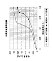
SAPO−34(UOP LLC社製:このサンプルの骨格構造のAl、P、Siの合計に対する各成分の構成割合(モル比)は、Si=3%、Al=52%、P=45%である)を吸着等温線測定装置(ベルソーブ18:日本ベル(株))により測定した。SAPO−34の40℃での吸着過程の水蒸気吸着等温線を図2に示す。なお、吸着等温線の測定は、空気高温槽温度50℃、吸着温度40℃、初期導入圧力3.0torr、導入圧力設定点数0、飽和蒸気圧55.33mmHg、平衡時間500秒で行った。一方、脱着過程の吸着等温線は磁気浮遊式天秤による吸着等温線測定装置(日本ベル(株))により測定した。脱着過程の吸着等温線の測定は、空気高温槽温度120℃、脱着温度90℃で50Torrずつ水蒸気を排気して重量変化を測定した。結果を図2に示す。
【0049】
車載用空調装置として一般車を想定した場合、T1=90℃、T2=40℃、T0=10℃の条件が考えられる。この時、脱着側相対水蒸気圧φ1=0.11、吸着側相対水蒸気圧φ2=0.17となり、φ1とφ2における吸着量差は0.21g/gであることが判る。目標とする吸着量差0.15g/gを上回り、一般車に用いる車両用空調装置として十分機能することが判る。
【0050】
また、一般車よりも低温風が求められる高級車の場合、T1=90℃、T2=40℃、T0=5℃の条件が考えられる。この時、φ1=0.11とφ2=0.12の間の吸着量は0.20g/gとなり、目標とする吸着量差0.15g/gを上回り、高級車用空調装置として十分機能することが判る。
さらに、地域によっては、厳しい外部環境から冷却水温度T2が45℃程度まで上昇することが予測される。この時、T1=90℃で一般車並みのT0=10℃を得る条件を考えてみる。ベルソープ18を用いて45℃での吸着過程の吸着等温線を測定した。90℃の脱着過程の吸着等温線と併せて図3に示す。45℃での吸着等温線の測定は、空気高温槽温度65℃、吸着温度45℃、初期導入圧力3.0torr、導入圧力設定点数0、飽和蒸気圧55.33mmHg、平衡時間500秒で行った。T1=90℃、T2=45℃、T0=10℃の場合、脱着側相対水蒸気圧φ1=0.14が吸着側相対水蒸気圧φ2=0.13を上回ってしまう。この様に脱着側の相対水蒸気圧が吸着側の相対水蒸気圧より低くなる場合でも、温度依存性のある実施例1では吸着量差が0.16g/g得られることがわかる。実施例1を水蒸気吸着材として用いた吸着ヒートポンプは高温地方でも十分作動することが判る。
【0051】
実施例2
水192gにアルミニウムイソプロポキシド108gを加えて撹拌した後、85%リン酸58gを加えて2時間撹拌した。この溶液にfumedシリカ(アエロジル200)1.8gを加えた後、さらに35%テトラエチルアンモニウムヒドロキシド(TEAOH)水溶液122.7gを加え、4時間撹拌した。この時のゲルの組成は以下の通りである。
Al2O3/0.95P2O5/0.11SiO2/1.1TEAOH/59H2O
この混合物をテフロン(登録商標)内筒入りの500ccステンレス製オートクレーブに仕込み、100rpmで撹拌しながら185℃で48時間反応させた。反応後、冷却し、遠心分離で生成物を分離、水洗し、120℃で乾燥した。これを空気気流下550℃6時間で焼成してゼオライトを得た。このゼオライトをXRDで測定すると、CHA構造であった。また、元素分析により、骨格構造のアルミニウム、リン、ケイ素の合計に対する各成分の構成割合(モル比)は、ケイ素が2.8%、アルミニウムが51.3%、リンが45.9%であった。
このゼオライトを実施例1と同じ測定方法により、40℃での吸着過程と90℃の脱着過程の吸着等温線の測定を行った。その結果を図4に示した。T1=90℃、T2=40℃、T0=10℃の条件の場合、脱着側相対水蒸気圧φ1=0.11、吸着側相対水蒸気圧φ2=0.17における吸着量差は0.18g/gである。
【0052】
実施例3
水135gに85%リン酸65.3gを加え、これに擬ベーマイト(25%含水、コンデア製)42.9gをゆっくり加え、3時間撹拌した。これをA液とする。これとは別に、fumedシリカ(アエロジル200)3.8g、モルホリン(MOR)27.5g、トリエチルアミン(Et3N)32.1g、水180gを混合した液を調整した。これをA液に撹拌しながらゆっくりと加えた。これをさらに4時間撹拌した。この時のゲルの組成は以下の通りである。
Al2O3/0.9P2O5/0.2SiO2/1MOR/1Et3N/65H2O
この混合物をテフロン(登録商標)内筒入りの500ccステンレス製オートクレーブに仕込み、100rpmで撹拌しながら190℃で60時間反応させた。反応後、冷却し、遠心分離で生成物を分離、水洗し、120℃で乾燥した。これを空気気流下550℃6時間で焼成してゼオライトを得た。このゼオライトをXRDで測定すると、CHA構造であった。また、元素分析により、骨格構造のアルミニウム、リン、ケイ素の合成に対する各成分の構成割合(モル比)は、ケイ素が7.2%、アルミニウムが49.9%、リンが42.9%であった。
このゼオライトを実施例1と同じ測定方法により、40℃での吸着過程と90℃の脱着過程の吸着等温線の測定を行った。その結果を図5に示した。T1=90℃、T2=40℃、T0=10℃の条件の場合、脱着側相対水蒸気圧φ1=0.11、吸着側相対水蒸気圧φ2=0.17における吸着量差は0.17g/gである。
【0053】
【発明の効果】
本発明の吸着ヒートポンプは、吸着材の吸脱着による水分吸着量の差が大きく、低温度で吸着材の再生(脱着)が可能になるため、従来に比べて低温の熱源で効率よく吸着ヒートポンプを駆動することができ、かつ吸着ヒートポンプをコンパクトにすることが可能となる。
【図面の簡単な説明】
【図1】吸着ヒートポンプの概念図である。
【図2】SAPO−34の40℃の吸着過程、90℃の脱着過程の水蒸気吸着等温線である。
【図3】SAPO−34の45℃の吸着過程、90℃の脱着過程の水蒸気吸着等温線である。
【図4】実施例2における40℃の吸着過程、90℃の脱着過程の水蒸気吸着等温線である。
【図5】実施例3における45℃の吸着過程、90℃の脱着過程の水蒸気吸着等温線である。
【符号の説明】
1 吸着塔
2 吸着塔
3 吸着質配管
4 蒸発器
5 凝縮器
11 熱媒配管
111 冷却水入口
112 冷却水出口
113 温水入口
114 温水出口
115 切り替えバルブ
116 切り替えバルブ
21 熱媒配管
211 冷却水入口
212 冷却水出口
213 温水入口
214 温水出口
215 切り替えバルブ
216 切り替えバルブ
30 吸着質配管
31 制御バルブ
32 制御バルブ
33 制御バルブ
34 制御バルブ
300 室内機
301 ポンプ
41 冷水配管(入口)
42 冷水配管(出口)
51 冷却水配管(入口)
52 冷却水配管(出口)[0001]
BACKGROUND OF THE INVENTION
The present invention relates to an adsorption heat pump using a specific adsorbent.
In particular, the present invention relates to an adsorption heat pump suitable for being mounted on an automobile.
[0002]
[Prior art]
In an adsorption heat pump, in order to regenerate an adsorbate, for example, an adsorbent that has adsorbed water, the adsorbent is heated to desorb the adsorbate, and the dried adsorbent is cooled to a temperature used for adsorbate adsorption. Used again for adsorbate adsorption. There is a need for an adsorption heat pump that generates cold using a low-temperature exhaust heat of 100 ° C. or less, or 60 ° C. to 90 ° C. obtained by cogeneration equipment, fuel cells, automobile engine cooling water, solar heat, and the like. In particular, there is a strong demand for commercialization of automobiles that generate a large amount of exhaust heat.
[0003]
For example, when the exhaust heat temperature is about 85 to 95 ° C. and the ambient temperature used for cooling is about 35 to 45 ° C., the adsorbent has a low relative adsorbate in order for the adsorption heat pump to operate sufficiently. It is necessary to perform adsorption / desorption with water vapor pressure, and in order to reduce the size of the apparatus by using a small amount of adsorbent, an adsorbent with a large adsorption / desorption amount is required. In order to use a low-temperature heat source for adsorbate desorption (regeneration of adsorbent), the desorption temperature needs to be low. That is, as an adsorbent used in an adsorption heat pump, (1) an adsorbate that adsorbs and desorbs adsorbate with a low relative water vapor pressure and (2) an adsorbent with a large amount of adsorption / desorption is desired. The use of various adsorbents as an adsorbent used in the adsorption heat pump has been studied, but there are various problems, and no adsorbent as described above has been found.
[0004]
In addition, it has already been reported that the temperature dependence of the adsorption property of the adsorbent for the adsorption heat pump is important (Chemical Engineering Papers, Vol. 19, No. 6 (1993), P1165-1170), and a large temperature dependence. SG3 (manufactured by Fuji Silysia) which shows sex and SG1 (same) which does not show are reported.
In addition, AlPO which is a porous aluminum phosphate molecular sieveFourIt has been reported that the adsorption performance of -5 depends on temperature, and specifically, the adsorption performance at 25 ° C. and 30 ° C. is shown (Colloid Polym Sci 277 (1999) p83-88). Similarly AlPOFourThe temperature dependence of -5 has been reported, and adsorption isotherms in the adsorption process at 20 ° C, 25 ° C, 30 ° C, 35 ° C, and 40 ° C are described (Proceedings of the 16th Zeolite Research Presentation Conference) p91; November 21 and 22, 2000).
However, conventionally, no attention has been paid to the desorption isotherm, the relationship between the adsorption isotherm and the desorption isotherm, and the adsorption isotherm and desorption isotherm.Relative water vapor pressureAbout the difference in adsorption amount is not known.
[0005]
[Problems to be solved by the invention]
The present invention provides an adsorption heat pump having practically effective adsorption performance.
[0006]
[Means for Solving the Problems]
The present inventors paid attention to the fact that the operating temperature of the adsorption / desorption part of the heat pump differs between adsorption and desorption of the adsorbate, and as a result of intensive studies, (1) the adsorption isotherm at the adsorption / desorption part temperature during the adsorption operation. And (2) knowledge that a heat pump using an adsorbent having a specific adsorption amount difference determined from the desorption isotherm at the adsorption / desorption temperature at the time of desorption operation has practically useful adsorption performance. Got. That is, there are adsorbents in which the adsorption isotherm does not change depending on the temperature and those that change (the latter change is abbreviated as having temperature dependence), and some zeolite and silica have temperature dependence. However, by focusing on the specific temperature dependency and adsorption amount difference that have not been recognized so far, the capacity of the adsorption heat pump can be reduced by using a material with a large adsorption amount difference in a specific range. In addition, the present inventors have found that a practical adsorption heat pump that operates with a relatively low-temperature heat source, which has not been able to achieve sufficient adsorption performance with waste heat of a vehicle or the like, can be provided.
That is, the gist of the present invention is as follows.
(A) an adsorbate, (b) an adsorption / desorption portion comprising an adsorbent for adsorbing / desorbing the adsorbate, (c) an evaporation portion for evaporating the adsorbate coupled to the adsorption / desorption portion, and (d) the adsorption / desorption portion. In an adsorption heat pump comprising a condensing unit for condensing adsorbate coupled to a desorption unit,
(1) The adsorbent has a skeletal structure with aluminum and phosphorus.Heteroatoms andIncluding zeolite,
(2) The adsorbent has a relative water vapor pressure φ2 of 0.115 or more and 0.18 or less during the adsorption operation of the adsorption / desorption portion, and a relative water vapor pressure φ1 of 0.1 or more and 0.14 or less during the desorption operation of the adsorption / desorption portion. It is a water vapor adsorbent having a range in which the adsorption amount difference of the adsorbent obtained by the following formula is 0.15 g / g or more in the region.
Adsorption heat pump characterized by that.
Adsorption amount difference = Q2-Q1
here,
Q1 = Adsorption amount at φ1 obtained from the water vapor desorption isotherm measured at the desorption operation temperature (T3) of the adsorption / desorption part
Q2 = Adsorption amount at φ2 obtained from the water vapor adsorption isotherm measured at the adsorption operation temperature (T4) of the adsorption / desorption part
However,
φ1 (relative water vapor pressure during desorption operation of the adsorption / desorption part) =Condensing partWater vapor pressure at the refrigerant temperature (T2) for cooling the refrigerant / equilibrium water vapor pressure at the heat medium temperature (T1) for heating the adsorption / desorption part
φ2 (relative water vapor pressure during adsorption operation of the adsorption / desorption part) = cooling temperature (T0) generated in the evaporation partEquilibrium water vapor pressure/ Of the refrigerant temperature (T2) for cooling the adsorption / desorption partEquilibrium water vapor pressure
(Here, T0 = 5 to 10 ° C., T1 = T3 = 90 ° C., T2 = T4 = 40 to 45 ° C.)
[0007]
DETAILED DESCRIPTION OF THE INVENTION
Hereinafter, the present invention will be described in more detail.
<Adsorption heat pump structure>
First, the structure of the adsorption heat pump will be described by taking the adsorption heat pump shown in FIG. 1 as an example.
[0008]
The adsorption heat pump is filled with an adsorbate and an adsorbent capable of adsorbing and desorbing the adsorbate and transfers heat generated by the adsorption and desorption of the adsorbate to the heat medium (adsorption towers 1 and 2, hereinafter referred to as an adsorption / desorption portion). May be referred to as an adsorption tower), an evaporation section (evaporator 4) for taking out the cold heat obtained by the evaporation of the adsorbate, and a condensation section (condensation) for releasing the heat obtained by the condensation of the adsorbate to the outside. It is mainly composed of the device 5).
[0009]
The evaporator 4 is filled with a refrigerant (in this embodiment, water) in a state where the inside is kept in a substantially vacuum, and heat that is exchanged with the air blown into the room by the
Adsorption towers 1 and 2 are on the surfaceAdsorbentIs stored in the heat exchanger, and the condenser 5 cools and condenses the vapor refrigerant (water vapor) desorbed from the adsorption towers 1 and 2 with a heat medium cooled by outside air or the like. A
[0010]
The adsorption towers 1 and 2 filled with the adsorbent are connected to each other by an
The evaporator 4 and the condenser 5 are connected to the
[0011]
A
[0012]
Hot water is introduced from the
[0013]
[0014]
The
[0015]
<Adsorption heat pump operation overview>
Next, an outline of the operation of the air conditioner (adsorption heat pump) according to this embodiment will be described. By operating the
[0016]
More specifically, when the first adsorption tower 1 is used as an adsorption process and the second adsorption tower 2 is used as a desorption process, the
[0017]
As a result, the refrigerant (water vapor) evaporated in the evaporator 4 flows into the first adsorption tower 1 and is adsorbed by the adsorbent therein, and the temperature of the adsorbent is outside air by the cooling water from the
On the other hand, since the hot water heated by the heat source (traveling engine when applied to a vehicle) is supplied to the second adsorption tower 2 from the
[0018]
After a predetermined time has elapsed, the first adsorption tower 1 is switched to the desorption process and the second adsorption tower 2 is switched to the adsorption process by switching the
<Adsorbent>
In the adsorbent of the present invention, the relative water vapor pressure φ2 during the adsorption operation of the adsorption / desorption part is 0.115 or more and 0.18 or less, and the relative water vapor pressure φ1 during the adsorption operation of the adsorption / desorption part is 0.1 or more and 0.14 or less. In the region, the water vapor adsorbent has a range in which the difference in adsorbent amount obtained by the following formula is 0.15 g / g or more.
[0019]
Adsorption amount difference = Q2-Q1
here,
Q1 = Adsorption amount at φ1 obtained from the water vapor desorption isotherm measured at the desorption operation temperature (T3) of the adsorption / desorption part
Q2 = Adsorption amount at φ2 obtained from the water vapor adsorption isotherm measured at the adsorption operation temperature (T4) of the adsorption / desorption part
However,
φ1 (relative water vapor pressure during desorption operation of the adsorption / desorption part) =Condensing partWater vapor pressure at the refrigerant temperature (T2) for cooling the refrigerant / equilibrium water vapor pressure at the heat medium temperature (T1) for heating the adsorption / desorption part
φ2 (relative water vapor pressure during adsorption operation of the adsorption / desorption part) = cooling temperature (T0) generated in the evaporation partEquilibrium water vapor pressure/ Of the refrigerant temperature (T2) for cooling the adsorption / desorption partEquilibrium water vapor pressure
(Here, T0 = 5 to 10 ° C., T1 = T3 = 90 ° C., T2 = T4 = 40 to 45 ° C.)
Although the adsorption amount difference of the adsorbent of the present invention is specified above, a more preferable adsorbent is an adsorbent specified under any of the following conditions (A) to (C).
[0020]
(A) T0 is 10 ° C, T2 is 40 ° C
(B) T0 is 5 ° C, T2 is 40 ° C
(C) T0 is 10 ° C, T2 is 45 ° C
Hereinafter, the performance of the adsorbent as described above will be described with reference to FIG.
First, in FIG. 1, the
[0021]
In this case, the water vapor supplied from the evaporator 4 is adsorbed, and the adsorbent filled in the adsorption tower 2 generates heat. At this time, the adsorption tower 2 is cooled and gradually heated by a heat medium (for example, cooling water) circulated from the heat
[0022]
On the other hand, the temperature of the evaporator 4 is controlled for the purpose of generating cold. At this time, the adsorption side relative water vapor pressure φ2 is defined by the following equation.
Adsorption side relative water vapor pressure φ2 = equilibrium water vapor pressure (T0) / equilibrium water vapor pressure (T2)
Equilibrium water vapor pressure (T0): Equilibrium water vapor pressure at temperature T0 of the evaporator 4
Equilibrium water vapor pressure (T2): Equilibrium water vapor pressure at heat medium temperature T2 of adsorption tower 2
At the same time, the adsorption tower 1 is in the process of desorption (regeneration), and the adsorbent filled in the adsorption tower 1 is regenerated by a regeneration heat source (the temperature of the heat medium that heats the adsorption / desorption section. This temperature is T1). . The condenser 5 is cooled by the cooling water supplied through the
[0023]
Desorption side relative water vapor pressure φ1 =Equilibrium water vapor pressure(T2) /Equilibrium water vapor pressure(T1)
Equilibrium water vapor pressure(T2): the temperature of the condenser 5Equilibrium water vapor pressure
(= Heat medium temperature T2 of the adsorption tower 2Equilibrium water vapor pressure)
Equilibrium water vapor pressure(T1): of the regeneration heat source temperature (T1) of the adsorption tower 1Equilibrium water vapor pressure
The important point here is that the adsorption tower is different in temperature during adsorption and desorption (regeneration). Therefore, in the present invention, the adsorption amount difference is obtained from the desorption isotherm at the desorption temperature and the adsorption isotherm at the adsorption temperature. Specifically, it is calculated by the following equation.
[0024]
Adsorption amount difference = Q2-Q1
here,
Q1 =Adsorption / desorption partAdsorption amount at φ1 obtained from water vapor desorption isotherm measured at desorption operation temperature (T3)
Q2 = Adsorption amount at φ2 obtained from the water vapor adsorption isotherm measured at the adsorption operation temperature (T4) of the adsorption / desorption part
However,
φ1 (relative water vapor pressure during desorption operation of the adsorption / desorption part) =Condensing partEquilibrium water vapor pressure of refrigerant temperature (T2) for cooling / heat medium temperature (T1) for heating the adsorption / desorption partEquilibrium water vapor pressure
φ2 (relative water vapor pressure during adsorption operation of the adsorption / desorption part) = cooling temperature (T0) generated in the evaporation partEquilibrium water vapor pressure/ Of the refrigerant temperature (T2) for cooling the adsorption / desorption partEquilibrium water vapor pressure
(Here, T0 = 5 to 10 ° C., T1 = T3 = 90 ° C., T2 = T4 = 40 to 45 ° C.)
In the adsorbent of the present invention, the difference in adsorption amount determined by the above formula is 0.15 g / g or more, preferably 0.18 g / g or more. The larger the difference in the amount of adsorption, the better, but it is usually about 0.25 g / g or less in consideration of an available material source satisfying such performance. Further, the larger the adsorption amount difference, the better. However, it is usually 0.50 g / g or less, practically 0.40 g / g or less, and further 0.35 g / g or less.
The difference in the amount of adsorption is 0.15 g / g or more, which is derived based on the following examination, assuming that the adsorption heat pump is applied to an automobile.
<Adsorption temperature, Desorption temperature>
First, as described above, since the adsorption amount depends on the temperature at the time of adsorption and the temperature at the time of desorption, an adsorption isotherm at the temperature at the time of adsorption and a desorption isotherm at the temperature at the time of desorption are obtained.
At the time of adsorption, the adsorption tower is cooled with cooling water in order to suppress heat generation due to heat of adsorption, so that the cooling water temperature (T2) is substantially equal to the adsorption temperature (T4). On the other hand, at the time of desorption, the adsorption tower needs desorption heat, and the hot water temperature (T1) becomes the desorption temperature (T3).
[0025]
By the way, the heat transfer medium temperature of the adsorption heat pump is (1) the hot water temperature is about 90 ° C. because it is obtained with engine cooling water, and (2) the cooling temperature is about 40 ° C. because it is the temperature obtained by heat exchange with the outside air. 45 ° C. (3) The temperature of the cold water necessary for producing cold air is approximately 5 to 10 ° C. That is, the cold water temperature is preferably about 10 ° C. on the premise of a general car model in Japan, and about 5 ° C. for a luxury car. The cooling temperature is about 40 ° C. in Japan, and about 45 ° C. in regions where the outside air temperature is high.
[0026]
Accordingly, the adsorption temperature (T4) is about 40 ° C. to 45 ° C., and the desorption temperature (T3) is about 90 ° C.
In the present invention, the adsorption temperature and the desorption temperature are employed as an index for evaluating the performance of the adsorbent, and at least one of the adsorption isotherms obtained at an adsorption temperature of 40 ° C. to 45 ° C., From the desorption isotherm obtained at a desorption temperature of 90 ° C., the difference in adsorption amount determined according to the above formula is 0.15 g / g or more.
[0027]
<Adsorption amount difference>
The said adsorption amount difference (0.15 g / g or more) is calculated | required according to the following.
That is, it is considered that the capacity of the adsorption heat pump is desirably at least 15 liters or less based on engine room surveys of various vehicles.
Next, it can be filled in a volume of 15 liters or lessAdsorbent weightAsk for.
[0028]
The parts to be mounted in the engine room include an adsorption tower body, an evaporator, a condenser, and control valves. It is necessary to make the assembly in which these are integrally formed into a capacity of 15 liters or less. In our study, it is considered that the size of the evaporator, condenser and valves can be formed with about 4.5 liters. Therefore, the capacity of the adsorption tower body is approximately 10.5 liters or less. In the adsorption towerAdsorbentFilling rate andAdsorbentThe bulk density is usually about 30% and about 0.6 kg / liter respectively, so it can be filledAdsorbent weight(W) is about 10.5 × 30% × 0.6 = 1.89 kg.
[0029]
nextAdsorbentThe characteristics required for the above will be described.
Generally, the steady cooling capacity required for a vehicle air conditioner is about 3 kW. The cooling capacity R in the adsorption heat pump is expressed by the following formula A.
R = (W · ΔQ · ηC · ΔH / τ) · ηh (Formula A)
Here, W is packed in one adsorption tower (one side)Adsorbent weight, ΔQ is the equilibrium adsorption amount amplitude (Q2−Q1) in the adsorption and desorption conditions, and ηC is the adsorption amplitude efficiency indicating the ratio of the actual adsorption amplitude within the switching time with respect to the equilibrium adsorption amplitude ΔQ, ΔH is the latent heat of vaporization of water, τ is the switching time between the adsorption process and the desorption process, and ηh isAdsorbentAnd heat mass efficiency in consideration of heat mass loss due to temperature change between the hot water temperature and the cooling water temperature by the heat exchanger.
[0030]
As described above, R is 3 kW, and W is 1.89 kg / 2 = 0.95 kg. In addition, from our past studies, τ is appropriately about 60 seconds, and ΔH, ηC, and ηh are about 2500 kJ / kg, 0.6, and 0.85, respectively. Asking
ΔQ = R / W / ηC / ΔH ・ τ / ηh = 3.0 / 0.95 / 0.6 / 2500 ・ 60 / 0.85 = 0.149kg / kg
It becomes. That is, it is used for an adsorption heat pump for automobiles.Adsorbentas,
It is preferable that the characteristic of ΔQ ≧ 0.15 g / g is satisfied.
[0031]
As described above, the description has been made on the assumption that it is applied to an automobile, but it goes without saying that it can be sufficiently applied to other uses such as stationary use as long as the above characteristics are satisfied.
The difference in the amount of adsorption in the present invention is that the relative water vapor pressure φ2 during the adsorption operation of the adsorption / desorption part is 0.115 or more and 0.18 or less, and the relative water vapor pressure φ1 during the adsorption operation of the adsorption / desorption part is 0.1 or more and 0.1. It is satisfied in the range of 14 or less. This range generally corresponds to the operating relative water vapor pressure range of the adsorption heat pump.
[0032]
When φ1 and φ2 are in the range of 0.115 to 0.18, and the region where φ1 is equal to or greater than φ2 has a range in which the difference in adsorption amount is 0.15 g / g or more, As an adsorption heat pump, it is advantageous because it operates even under severe temperature conditions that were previously thought not to operate.
<Adsorbent material>
The adsorbent which is one of the features of the present invention is to contain a zeolite containing aluminum and phosphorus in the skeleton structure. The zeolite here may be a natural zeolite or an artificial zeolite. For example, an artificial zeolite includes aluminosilicates, aluminophosphates and the like as defined by the International Zeolite Association (IZA).
[0033]
In the present invention,Among them, aluminum, phosphorus, and heteroatoms are used in the skeletal structure in which a part of aluminum and phosphorus are substituted with heteroatoms for imparting hydrophilicity.WhenZeolite containingUse. Examples of the hetero atom include silicon, lithium, magnesium, titanium, zirconium, vanadium, chromium, manganese, iron, cobalt, nickel, palladium, copper, zinc, gallium, germanium, arsenic, tin, calcium, or boron.
[0034]
The heteroatom is preferably silicon, magnesium, titanium, zirconium, iron, cobalt, zinc, gallium or boron, most preferably silicon, commonly referred to as SAPO. These heteroatoms may be substituted with two or more of aluminum and phosphorus in the skeleton.
As a preferred zeolite used as an adsorbent in the present invention, a zeolite containing aluminum, phosphorus and a heteroatom in the skeleton structure, the abundance ratio of atoms represented by the following formulas (1), (2) and (3) What has is preferable.
[0035]
0.001 ≦ x ≦ 0.3 (1)
(Wherein x represents the molar ratio of heteroatoms to the total of aluminum, phosphorus and heteroatoms in the skeleton structure)
0.3 ≦ y ≦ 0.6 (2)
(Wherein y represents the molar ratio of aluminum to the total of aluminum, phosphorus and heteroatoms in the skeleton structure)
0.3 ≦ z ≦ 0.6 (3)
(Wherein z represents the molar ratio of phosphorus to the total of aluminum, phosphorus and heteroatoms in the skeleton structure)
And among the above-mentioned proportions of atoms, the heteroatoms are represented by the following formula (4).
0.003 ≦ x ≦ 0.25 (4)
(Wherein x is as defined above)
Is preferably represented by the following formula (5):
0.005 ≦ x ≦ 0.2 (5)
(Wherein x is as defined above) is more preferred.
[0036]
In addition, the zeolite used as the adsorbent in the present invention has a framework density of 10.0 T / 1,000 kg.Three16.0T / 1,000ÅThreeOr less, more preferably 10.0T / 1,000T.Three15.0 / 1,000ÅThreeZeolite in the following range. Here, the framework density is 1,000 kg of zeolite.ThreeThis means the number of elements constituting the framework other than oxygen, and this value is determined by the structure of the zeolite.
[0037]
The structure of such a zeolite can be represented by a code defined by IZA, AFG, MER, LIO, LOS, PHI, BOG, ERI, OFF, PAU, EAB, AFT, LEV, LTN, AEI, AFR, AFX, GIS , KFI, CHA, GME, THO, MEI, VFI, AFS, LTA, FAU, RHO, DFO, EMT, AFY, * BEA, etc., preferably AEI, GIS, KFI, CHA, GME, VFI, AFS, LTA , FAU, RHO, EMT, AFY, * BEA.
[0038]
Framework density correlates with pore volume, and in general, lower framework density zeolites have greater pore volume and therefore higher adsorption capacity. Further, it is expected that zeolite that is not currently synthesized can be suitably used as an adsorbent in the present invention if the framework density is within this region when synthesized.
[0039]
For example, in the case of an aluminophosphate having a CHA structure, a desired adsorption performance can be obtained by using a silicoaluminophosphate known as SAPO-34 or ZYT-6 in which atoms such as silicon are included in the skeleton. . A method for synthesizing SAPO-34 is described in US Pat. No. 4,440,871 and the like. Methods for synthesizing ZYT-6 are described in JP-B-4-37007, JP-B-5-21844, JP-B-5-51533, and the like.
[0040]
Further, when the zeolite is an aluminosilicate, silicon in the skeleton, a part of aluminum (may be all in the case of aluminum) is another atom such as magnesium, titanium, zirconium, vanadium, chromium, manganese, iron, It may be substituted with cobalt, zinc, gallium, tin, boron or the like. In the case of aluminosilicate, if the molar ratio of silicon and aluminum (aluminum + heteroatom) is too small, it is rapidly adsorbed in a too low humidity region, as in 13X, which is generally known as a water vapor adsorbent. If it is too large, it is too hydrophobic to adsorb water very much. Therefore, the zeolite used in the present invention preferably has a silicon / aluminum molar ratio of 4 or more and 20 or less, more preferably 4.5 or more and 18 or less, and particularly preferably 5 or more and 16 or less.
[0041]
These zeolites include those having exchangeable cationic species. In this case, the cationic species include alkaline elements such as protons, Li and Na, alkaline earth elements such as Mg and Ca, and rare earths such as La and Ce. Examples thereof include transition metals such as elements, Fe, Co, and Ni, and protons, alkali elements, alkaline earth elements, and rare earth elements are preferable. Furthermore, proton, Li, Na, K, Mg, and Ca are more preferable.
One example of a particularly preferred adsorbent used in the present invention is SAPO-34. SAPO-34 is CHA type (Framework density = 14.6T / 1,0001 ,)Three) Zeolite.
The adsorbent of the present invention may contain the above-mentioned zeolite and have the above-described adsorption amount difference, but the zeolite itself preferably has the adsorption amount difference defined in the present invention.
[0042]
Further, within the range of achieving the adsorption amount difference defined in the present invention, zeolite may be used alone or in combination of plural kinds, and adsorbents other than zeolite, such as silica, alumina, activated carbon, clay, etc. may be used as zeolite. And may be used in combination.
<Driving method>
Next, the operation method of the adsorption heat pump will be described with reference to FIG.
[0043]
First stepThen,
[0044]
When the adsorption tower 2 is cooled, cooling water cooled by exchanging heat with outside air, river water, etc. by a heat exchanger such as a cooling tower is introduced through the
[0045]
The adsorption tower 1 in the regeneration step is usually heated with hot water of 40 to 100 ° C., preferably 50 to 98 ° C., more preferably 60 to 95 ° C., and reaches an equilibrium water vapor pressure corresponding to the temperature range. It is condensed with a saturated vapor pressure at a condensation temperature of 20-50 ° C. (this is equal to the temperature of the cooling water cooling the condenser). Water vapor moves from the adsorption tower 1 to the condenser 5 and is condensed to become water. Water is returned to the evaporator 4 by the return pipe 3. From the relationship between the temperature of the cooling water and the temperature of the heating medium (hot water) used for regeneration, the desorption side relative water vapor pressure φ1 (where φ1 is the amount of adsorbate at the cooling water temperature)Equilibrium water vapor pressureOf the adsorbate at the temperature of the heating medium (hot water) used for regenerationEquilibrium water vapor pressureIs determined by dividing by (1), but φ1 is defined by the present invention.AdsorbentIt is preferable to operate so that becomes smaller than the relative water vapor pressure at which water vapor is rapidly adsorbed. If φ1 is defined by the present inventionAdsorbentIs greater than the relative water vapor pressure that rapidly adsorbs water vapor, as defined in the present invention.AdsorbentThis is because the excellent amount of adsorption cannot be effectively used. φ1 can be appropriately set according to the environmental temperature or the like, but the adsorption heat pump is operated under a temperature condition in which the adsorption amount at φ1 is usually 0.1 or more and 0.18 or less. The operation is performed so that the difference between the adsorbate adsorption amount at φ1 and the adsorbate adsorption amount at φ2 is usually 0.15 g / g or more, preferably 0.18 g / g or more. Specifically, TO is approximately 5 to 10 ° C, T1 and T3 are 90 ° C, and T2 and T4 are 40 to 45 ° C. More thanFirst stepIt is.
[0046]
nextSecond stepThen, by switching the
[0047]
Here, the operation method in the case where two adsorption towers are installed has been described. However, by properly desorbing the adsorbate adsorbed by the adsorbent, one of the adsorption towers can maintain a state in which the adsorbate can be adsorbed. If possible, any number of adsorption towers may be installed.
In addition, the said adsorbent which has the specific performance of this invention can be used for the adsorption | suction part of conventionally well-known various air conditioners represented by an adsorption heat pump or a dehumidification air conditioner.
[0048]
【Example】
EXAMPLES Hereinafter, although an Example demonstrates this invention further more concretely, this invention is not limited at all by the following examples.
Example 1
SAPO-34 (manufactured by UOP LLC: the composition ratio (molar ratio) of each component with respect to the total of Al, P, and Si in the skeleton structure of this sample is Si = 3%, Al = 52%, and P = 45%. ) Was measured with an adsorption isotherm measuring device (Belsorb 18: Nippon Bell Co., Ltd.). The water vapor adsorption isotherm of the adsorption process of SAPO-34 at 40 ° C. is shown in FIG. The measurement of the adsorption isotherm was performed at an air high temperature bath temperature of 50 ° C., an adsorption temperature of 40 ° C., an initial introduction pressure of 3.0 torr, an introduction pressure set point of 0, a saturated vapor pressure of 55.33 mmHg, and an equilibrium time of 500 seconds. On the other hand, the adsorption isotherm in the desorption process was measured by an adsorption isotherm measuring device (Nippon Bell Co., Ltd.) using a magnetic floating balance. In the desorption process, the adsorption isotherm was measured by evacuating water vapor in increments of 50 Torr at an air hot bath temperature of 120 ° C. and a desorption temperature of 90 ° C., and measuring the weight change. The results are shown in FIG.
[0049]
When a general vehicle is assumed as an in-vehicle air conditioner, conditions of T1 = 90 ° C., T2 = 40 ° C., and T0 = 10 ° C. can be considered. At this time, the desorption side relative water vapor pressure φ1 = 0.11 and the adsorption side relative water vapor pressure φ2 = 0.17, and it is found that the adsorption amount difference between φ1 and φ2 is 0.21 g / g. It exceeds the target adsorption amount difference of 0.15 g / g, and it can be seen that it sufficiently functions as a vehicle air conditioner used for ordinary vehicles.
[0050]
Further, in the case of a high-class vehicle that requires a colder air than a general vehicle, conditions of T1 = 90 ° C., T2 = 40 ° C., and T0 = 5 ° C. can be considered. At this time, the adsorption amount between φ1 = 0.11 and φ2 = 0.12 is 0.20 g / g, which exceeds the target adsorption amount difference of 0.15 g / g, and sufficiently functions as an air conditioner for a luxury car. I understand that.
Furthermore, depending on the region, it is predicted that the cooling water temperature T2 will rise to about 45 ° C. from a severe external environment. At this time, let us consider a condition for obtaining T0 = 10 ° C. which is similar to that of a general car at T1 = 90 ° C. The adsorption isotherm of the adsorption process at 45 ° C. was measured using a bell soap 18. FIG. 3 shows the adsorption isotherm of the 90 ° C. desorption process. The measurement of the adsorption isotherm at 45 ° C. was performed at an air high temperature bath temperature of 65 ° C., an adsorption temperature of 45 ° C., an initial introduction pressure of 3.0 torr, an introduction pressure set point of 0, a saturated vapor pressure of 55.33 mmHg, and an equilibration time of 500 seconds. . When T1 = 90 ° C., T2 = 45 ° C., T0 = 10 ° C.Desorption side relative water vapor pressureφ1 = 0.14Adsorption side water vapor pressureIt exceeds φ2 = 0.13. Thus, even when the relative water vapor pressure on the desorption side is lower than the relative water vapor pressure on the adsorption side, it can be seen that the adsorption amount difference of 0.16 g / g is obtained in Example 1 having temperature dependency. It can be seen that the adsorption heat pump using Example 1 as the water vapor adsorbent operates sufficiently even in a high temperature region.
[0051]
Example 2
After adding 108 g of aluminum isopropoxide to 192 g of water and stirring, 58 g of 85% phosphoric acid was added and stirred for 2 hours. After adding 1.8 g of fumed silica (Aerosil 200) to this solution, 122.7 g of 35% tetraethylammonium hydroxide (TEAOH) aqueous solution was further added and stirred for 4 hours. The composition of the gel at this time is as follows.
Al2OThree/0.95P2OFive/0.11SiO2/1.1 TEAOH / 59H2O
This mixture was charged into a 500 cc stainless steel autoclave containing a Teflon (registered trademark) inner cylinder and reacted at 185 ° C. for 48 hours while stirring at 100 rpm. After the reaction, the mixture was cooled, and the product was separated by centrifugation, washed with water, and dried at 120 ° C. This was calcined at 550 ° C. for 6 hours in an air stream to obtain zeolite. When this zeolite was measured by XRD, it had a CHA structure. In addition, by elemental analysis, the composition ratio (molar ratio) of each component to the total of aluminum, phosphorus, and silicon in the skeleton structure was 2.8% for silicon, 51.3% for aluminum, and 45.9% for phosphorus. It was.
The zeolite was measured for adsorption isotherms in the adsorption process at 40 ° C. and the desorption process at 90 ° C. by the same measurement method as in Example 1. The results are shown in FIG. In the case of T1 = 90 ° C., T2 = 40 ° C., T0 = 10 ° C.Desorption side relative water vapor pressureφ1 = 0.11Adsorption side water vapor pressureThe difference in adsorption amount at φ2 = 0.17 is 0.18 g / g.
[0052]
Example 3
65.3 g of 85% phosphoric acid was added to 135 g of water, and 42.9 g of pseudoboehmite (containing 25% water, manufactured by Condea) was slowly added thereto, followed by stirring for 3 hours. This is A liquid. Separately, 3.8 g of fumed silica (Aerosil 200), 27.5 g of morpholine (MOR), triethylamine (EtThreeN) A liquid in which 32.1 g and 180 g of water were mixed was prepared. This was slowly added to solution A with stirring. This was further stirred for 4 hours. The composition of the gel at this time is as follows.
Al2OThree/0.9P2OFive/0.2SiO2/ 1MOR / 1EtThreeN / 65H2O
This mixture was charged in a 500 cc stainless steel autoclave containing a Teflon (registered trademark) inner cylinder and reacted at 190 ° C. for 60 hours while stirring at 100 rpm. After the reaction, the mixture was cooled, and the product was separated by centrifugation, washed with water, and dried at 120 ° C. This was calcined at 550 ° C. for 6 hours in an air stream to obtain zeolite. When this zeolite was measured by XRD, it had a CHA structure. In addition, by elemental analysis, the composition ratio (molar ratio) of each component with respect to the synthesis of aluminum, phosphorus, and silicon having a skeletal structure was 7.2% for silicon, 49.9% for aluminum, and 42.9% for phosphorus. It was.
The zeolite was measured for adsorption isotherms in the adsorption process at 40 ° C. and the desorption process at 90 ° C. by the same measurement method as in Example 1. The results are shown in FIG. In the case of T1 = 90 ° C., T2 = 40 ° C., T0 = 10 ° C.Desorption side relative water vapor pressureφ1 = 0.11Adsorption side water vapor pressureThe difference in adsorption amount at φ2 = 0.17 is 0.17 g / g.
[0053]
【The invention's effect】
The adsorption heat pump of the present invention has a large difference in moisture adsorption amount due to adsorption / desorption of the adsorbent, and the adsorbent can be regenerated (desorbed) at a low temperature. It can be driven and the adsorption heat pump can be made compact.
[Brief description of the drawings]
FIG. 1 is a conceptual diagram of an adsorption heat pump.
FIG. 2 is a water vapor adsorption isotherm of a 40 ° C. adsorption process and a 90 ° C. desorption process of SAPO-34.
FIG. 3 is a water vapor adsorption isotherm of a 45 ° C. adsorption process and a 90 ° C. desorption process of SAPO-34.
4 is a water vapor adsorption isotherm in an adsorption process at 40 ° C. and a desorption process at 90 ° C. in Example 2. FIG.
5 is a water vapor adsorption isotherm in an adsorption process at 45 ° C. and a desorption process at 90 ° C. in Example 3. FIG.
[Explanation of symbols]
1 Adsorption tower
2 Adsorption tower
3 Adsorbate piping
4 Evaporator
5 Condenser
11 Heating medium piping
111 Cooling water inlet
112 Cooling water outlet
113 Hot water inlet
114 Hot water outlet
115 switching valve
116 Switching valve
21 Heating medium piping
211 Cooling water inlet
212 Cooling water outlet
213 Hot water inlet
214 Hot water outlet
215 Switching valve
216 switching valve
30 Adsorbate piping
31 Control valve
32 Control valve
33 Control valve
34 Control valve
300 Indoor unit
301 pump
41 Cold water piping (inlet)
42 Cold water piping (exit)
51 Cooling water piping (inlet)
52 Cooling water piping (exit)
Claims (19)
(1)吸着材が骨格構造にアルミニウムとリンとヘテロ原子とを含むゼオライトを含み、
(2)吸着材が、吸脱着部の吸着操作時相対水蒸気圧φ2が0.115以上0.18以下、吸脱着部の脱着操作時相対水蒸気圧φ1が0.1以上0.14以下である領域に、下記式で求められる吸着材の吸着量差が0.15g/g以上となる範囲を有する水蒸気吸着材である、ことを特徴とする吸着ヒートポンプ。
吸着量差=Q2−Q1
ここで、
Q1=吸脱着部の脱着操作温度(T3)で測定した水蒸気脱着等温線から求めたφ1における吸着量
Q2=吸脱着部の吸着操作温度(T4)で測定した水蒸気吸着等温線から求めたφ2における吸着量
但し、
φ1(吸脱着部の脱着操作時相対水蒸気圧)=凝縮部を冷却する冷媒温度(T2)の平衡水蒸気圧/該吸脱着部を加熱する熱媒温度(T1)での平衡水蒸気圧
φ2(吸脱着部の吸着操作時相対水蒸気圧)=蒸発部で生成される冷熱温度(T0)の平衡水蒸気圧/該吸脱着部を冷却する冷媒温度(T2)の平衡水蒸気圧
(ここで、T0=5〜10℃、T1=T3=90℃、T2=T4=40〜45℃とする)(A) an adsorbate, (b) an adsorption / desorption portion comprising an adsorbent for adsorbing / desorbing the adsorbate, (c) an evaporation portion for evaporating the adsorbate coupled to the adsorption / desorption portion, and (d) the adsorption / desorption portion. In an adsorption heat pump comprising a condensing unit for condensing adsorbate coupled to a desorption unit,
(1) The adsorbent includes zeolite containing aluminum, phosphorus, and heteroatoms in the skeleton structure,
(2) The adsorbent has a relative water vapor pressure φ2 of 0.115 or more and 0.18 or less during the adsorption operation of the adsorption / desorption portion, and a relative water vapor pressure φ1 of 0.1 or more and 0.14 or less during the desorption operation of the adsorption / desorption portion. An adsorption heat pump characterized by being a water vapor adsorbent having a range in which a difference in adsorbent amount obtained by the following formula is 0.15 g / g or more in a region.
Adsorption amount difference = Q2-Q1
here,
Q1 = Adsorption amount in φ1 obtained from the water vapor desorption isotherm measured at the desorption operation temperature (T3) of the adsorption / desorption part Q2 = In φ2 obtained from the water vapor adsorption isotherm measured in the adsorption operation temperature (T4) of the adsorption / desorption part Adsorption amount However,
φ1 (relative water vapor pressure at the time of desorption operation of the adsorption / desorption part) = equilibrium water vapor pressure of the refrigerant temperature (T2) for cooling the condensing part / equilibrium water vapor pressure at the heat medium temperature (T1) for heating the adsorption / desorption part φ2 (absorption) equilibrium water vapor pressure of the refrigerant temperature for cooling the equilibrium water vapor pressure / suction desorption portion of the adsorption operation when a relative vapor pressure of the desorption unit) = cold temperatures generated by the evaporation portion (T0) (T2) (where, T0 = 5 -10 ° C, T1 = T3 = 90 ° C, T2 = T4 = 40-45 ° C)
0.001≦x≦0.3
(x=骨格構造のアルミニウムとリンとヘテロ原子の合計に対するヘテロ原子のモル比)
0.3≦y≦0.6
(y=骨格構造のアルミニウムとリンとヘテロ原子の合計に対するアルミニウムのモル比)
0.3≦z≦0.6
(z=骨格構造のアルミニウムとリンとヘテロ原子の合計に対するリンのモル比)
であることを特徴とする請求項1〜5のいずれかに記載の吸着ヒートポンプ。The abundance of aluminum, phosphorus and heteroatoms in the zeolite
0.001 ≦ x ≦ 0.3
(X = molar ratio of heteroatoms to the total of aluminum, phosphorus and heteroatoms in the skeleton structure)
0.3 ≦ y ≦ 0.6
(Y = molar ratio of aluminum to the sum of aluminum, phosphorus and heteroatoms in the framework structure)
0.3 ≦ z ≦ 0.6
(Z = molar ratio of phosphorus to the sum of aluminum, phosphorus and heteroatoms in the skeletal structure)
The adsorption heat pump according to any one of claims 1 to 5, wherein
(1)吸着材が骨格構造にアルミニウムとリンとヘテロ原子とを含むゼオライトを含み、
(2)吸着材が、吸脱着部の吸着操作時相対水蒸気圧φ2が0.115以上0.18以下、吸脱着部の脱着操作時相対水蒸気圧φ1が0.1以上0.14以下である領域に、下記式で求められる吸着材の吸着量差が0.15g/g以上となる範囲を有する水蒸気吸着材である、ことを特徴とする吸着材の使用方法。
吸着量差=Q2−Q1
ここで、
Q1=吸脱着部の脱着操作温度(T3)で測定した水蒸気脱着等温線から求めたφ1における吸着量
Q2=吸脱着部の吸着操作温度(T4)で測定した水蒸気吸着等温線から求めたφ2における吸着量
但し、
φ1(吸脱着部の脱着操作時相対水蒸気圧)=凝縮部を冷却する冷媒温度(T2)の平衡水蒸気圧/該吸脱着部を加熱する熱媒温度(T1)での平衡水蒸気圧
φ2(吸脱着部の吸着操作時相対水蒸気圧)=蒸発部で生成される冷熱温度(T0)の平衡水蒸気圧/該吸脱着部を冷却する冷媒温度(T2)の平衡水蒸気圧
(ここで、T0=5〜10℃、T1=T3=90℃、T2=T4=40〜45℃とする)In the method of using an adsorbent in which the adsorbent is heated to desorb the adsorbate, and the dried adsorbent is cooled to a temperature used for adsorbate adsorption and used again for adsorbate adsorption. ) The adsorbent comprises a zeolite containing aluminum, phosphorus and heteroatoms in the framework structure;
(2) The adsorbent has a relative water vapor pressure φ2 of 0.115 or more and 0.18 or less during the adsorption operation of the adsorption / desorption portion, and a relative water vapor pressure φ1 of 0.1 or more and 0.14 or less during the desorption operation of the adsorption / desorption portion. A method of using an adsorbent characterized by being a water vapor adsorbent having a range in which an adsorption amount difference of the adsorbent obtained by the following formula is 0.15 g / g or more.
Adsorption amount difference = Q2-Q1
here,
Q1 = Adsorption amount in φ1 obtained from the water vapor desorption isotherm measured at the desorption operation temperature (T3) of the adsorption / desorption part Q2 = In φ2 obtained from the water vapor adsorption isotherm measured in the adsorption operation temperature (T4) of the adsorption / desorption part Adsorption amount However,
φ1 (relative water vapor pressure at the time of desorption operation of the adsorption / desorption part) = equilibrium water vapor pressure of the refrigerant temperature (T2) for cooling the condensing part / equilibrium water vapor pressure at the heat medium temperature (T1) for heating the adsorption / desorption part φ2 (absorption) equilibrium water vapor pressure of the refrigerant temperature for cooling the equilibrium water vapor pressure / suction desorption portion of the adsorption operation when a relative vapor pressure of the desorption unit) = cold temperatures generated by the evaporation portion (T0) (T2) (where, T0 = 5 -10 ° C, T1 = T3 = 90 ° C, T2 = T4 = 40-45 ° C)
(1)吸着材が骨格構造にアルミニウムとリンとヘテロ原子とを含むゼオライトを含む
(2)吸着材が、(a)吸着質、(b)吸着質を吸脱着する吸着材を備えた吸脱着部、(c)該吸脱着部に連結された吸着質の蒸発を行う蒸発部、及び(d)該吸脱着部に連結された吸着質の凝縮を行う凝縮部とを備えた吸着ヒートポンプに適用した場合に、吸脱着部の吸着操作時相対水蒸気圧φ2が0.115以上0.18以下、吸脱着部の脱着操作時相対水蒸気圧φ1が0.1以上0.14以下である領域に、下記式で求められる吸着材の吸着量差が0.15g/g以上となる範囲を有する
吸着量差=Q2−Q1
ここで、
Q1=吸脱着部の脱着操作温度(T3)で測定した水蒸気脱着等温線から求めたφ1における吸着量
Q2=吸脱着部の吸着操作温度(T4)で測定した水蒸気吸着等温線から求めたφ2における吸着量
但し、
φ1(吸脱着部の脱着操作時相対水蒸気圧)=凝縮部を冷却する冷媒温度(T2)の平衡水蒸気圧/該吸脱着部を加熱する熱媒温度(T1)での平衡水蒸気圧
φ2(吸脱着部の吸着操作時相対水蒸気圧)=蒸発部で生成される冷熱温度(T0)の平衡水蒸気圧/該吸脱着部を冷却する冷媒温度(T2)の平衡水蒸気圧
(ここで、T0=5〜10℃、T1=T3=90℃、T2=T4=40〜45℃とする)An adsorbent for a dehumidifying air conditioner, which satisfies the following (1) and (2).
(1) The adsorbent contains zeolite containing aluminum, phosphorus and heteroatoms in the skeleton structure. (2) The adsorbent comprises (a) an adsorbate, and (b) an adsorbent that adsorbs and desorbs the adsorbate. And (c) an evaporating unit for evaporating adsorbate coupled to the adsorption / desorption unit, and (d) a condensing unit for condensing the adsorbate coupled to the adsorption / desorption unit. The relative water vapor pressure φ2 during the adsorption operation of the adsorption / desorption portion is 0.115 or more and 0.18 or less, and the relative water vapor pressure φ1 during the adsorption / desorption operation of the adsorption / desorption portion is 0.1 or more and 0.14 or less, Adsorption amount difference having a range in which the adsorption amount difference of the adsorbent obtained by the following formula is 0.15 g / g or more = Q2-Q1
here,
Q1 = Adsorption amount in φ1 obtained from the water vapor desorption isotherm measured at the desorption operation temperature (T3) of the adsorption / desorption part Q2 = In φ2 obtained from the water vapor adsorption isotherm measured in the adsorption operation temperature (T4) of the adsorption / desorption part Adsorption amount However,
φ1 (relative water vapor pressure at the time of desorption operation of the adsorption / desorption part) = equilibrium water vapor pressure of the refrigerant temperature (T2) for cooling the condensing part / equilibrium water vapor pressure at the heat medium temperature (T1) for heating the adsorption / desorption part φ2 (absorption) equilibrium water vapor pressure of the refrigerant temperature for cooling the equilibrium water vapor pressure / suction desorption portion of the adsorption operation when a relative vapor pressure of the desorption unit) = cold temperatures generated by the evaporation portion (T0) (T2) (where, T0 = 5 -10 ° C, T1 = T3 = 90 ° C, T2 = T4 = 40-45 ° C)
0.001≦x≦0.3
(x=骨格構造のアルミニウムとリンとヘテロ原子の合計に対するヘテロ原子のモル比)
0.3≦y≦0.6
(y=骨格構造のアルミニウムとリンとヘテロ原子の合計に対するアルミニウムのモル比)
0.3≦z≦0.6
(z=骨格構造のアルミニウムとリンとヘテロ原子の合計に対するリンのモル比)
であることを特徴とする請求項12〜16のいずれかに記載の除湿空調装置用吸着材。The abundance of aluminum, phosphorus and heteroatoms in the zeolite
0.001 ≦ x ≦ 0.3
(X = molar ratio of heteroatoms to the total of aluminum, phosphorus and heteroatoms in the skeleton structure)
0.3 ≦ y ≦ 0.6
(Y = molar ratio of aluminum to the sum of aluminum, phosphorus and heteroatoms in the framework structure)
0.3 ≦ z ≦ 0.6
(Z = molar ratio of phosphorus to the sum of aluminum, phosphorus and heteroatoms in the skeletal structure)
The adsorbent for a dehumidifying air conditioner according to any one of claims 12 to 16, wherein
Priority Applications (1)
| Application Number | Priority Date | Filing Date | Title |
|---|---|---|---|
| JP2002202762A JP4112298B2 (en) | 2001-12-14 | 2002-07-11 | Adsorption heat pump |
Applications Claiming Priority (3)
| Application Number | Priority Date | Filing Date | Title |
|---|---|---|---|
| JP2001-382029 | 2001-12-14 | ||
| JP2001382029 | 2001-12-14 | ||
| JP2002202762A JP4112298B2 (en) | 2001-12-14 | 2002-07-11 | Adsorption heat pump |
Publications (3)
| Publication Number | Publication Date |
|---|---|
| JP2003240382A JP2003240382A (en) | 2003-08-27 |
| JP2003240382A5 JP2003240382A5 (en) | 2005-06-23 |
| JP4112298B2 true JP4112298B2 (en) | 2008-07-02 |
Family
ID=27790878
Family Applications (1)
| Application Number | Title | Priority Date | Filing Date |
|---|---|---|---|
| JP2002202762A Expired - Fee Related JP4112298B2 (en) | 2001-12-14 | 2002-07-11 | Adsorption heat pump |
Country Status (1)
| Country | Link |
|---|---|
| JP (1) | JP4112298B2 (en) |
Families Citing this family (4)
| Publication number | Priority date | Publication date | Assignee | Title |
|---|---|---|---|---|
| JP4654580B2 (en) * | 2004-01-23 | 2011-03-23 | 三菱化学株式会社 | Operation method of adsorption heat pump |
| JP4654582B2 (en) * | 2004-02-20 | 2011-03-23 | 三菱化学株式会社 | Adsorption heat pump operation method, adsorption heat pump, humidity control air conditioner operation method, and humidity control air conditioner |
| JP5647879B2 (en) * | 2010-12-13 | 2015-01-07 | 新日本空調株式会社 | Adsorption refrigeration system |
| JP2016050715A (en) * | 2014-08-29 | 2016-04-11 | カルソニックカンセイ株式会社 | Air conditioning system with adsorption type refrigerator |
-
2002
- 2002-07-11 JP JP2002202762A patent/JP4112298B2/en not_active Expired - Fee Related
Also Published As
| Publication number | Publication date |
|---|---|
| JP2003240382A (en) | 2003-08-27 |
Similar Documents
| Publication | Publication Date | Title |
|---|---|---|
| US7497089B2 (en) | Adsorption heat pump and use of adsorbent as adsorbent for adsorption heat pump | |
| US7422993B2 (en) | Adsorbent for adsorption heat pump, adsorbent for humidity-control air conditioner, adsorption heat pump and humidity-control air conditioner | |
| US20040093876A1 (en) | Adsorbent for heat utilization system, adsorbent for regenerator system, regenerator system comprising the adsorbent, ferroaluminophosphate and method for production thereof | |
| JP4669914B2 (en) | Adsorption heat pump, vehicle air conditioner, dehumidifying air conditioner, and method of using adsorbent | |
| JP4542738B2 (en) | Adsorption heat pump, adsorption material for adsorption heat pump, and air conditioner for vehicle | |
| JP3979327B2 (en) | Adsorbent for adsorption heat pump, adsorption heat pump, and operation method of adsorption heat pump | |
| JP4896110B2 (en) | Zeolite and adsorbent | |
| JP5161340B2 (en) | Adsorbent for adsorption heat pump and adsorption heat pump using the same | |
| JP2004132690A (en) | Adsorbent for thermal storage system, thermal storage system using it, iron aluminophosphate, and its manufacturing method | |
| JP4112298B2 (en) | Adsorption heat pump | |
| JP4654580B2 (en) | Operation method of adsorption heat pump | |
| JP4249437B2 (en) | Adsorption heat pump, adsorption heat pump operation method, and vehicle air conditioner using adsorption heat pump | |
| CN100422662C (en) | Adsorption heat pump and use of adsorbent as adsorbent for adsoprtion heat pump | |
| JP4661772B2 (en) | Humidity conditioning air-conditioning adsorbent, humidity conditioning air conditioner and operation method thereof | |
| JP4710023B2 (en) | Adsorption heat pump, vehicle air conditioner, dehumidifying air conditioner, and method of using adsorbent | |
| JP4654582B2 (en) | Adsorption heat pump operation method, adsorption heat pump, humidity control air conditioner operation method, and humidity control air conditioner | |
| JP2008267802A (en) | Adsorption heat pump, air conditioner for vehicle, adsorption heat pump operating method, adsorbent for adsorption heat pump, and application method of adsorbent | |
| JP4354755B2 (en) | Adsorbent for adsorption heat pump and adsorption heat pump using the same | |
| JP5544237B2 (en) | Low temperature desorption material, production method thereof, and low temperature desorption method | |
| JP2005098647A (en) | Adsorption type cooler | |
| Inagaki et al. | Kakiuchi et al. |
Legal Events
| Date | Code | Title | Description |
|---|---|---|---|
| RD02 | Notification of acceptance of power of attorney |
Free format text: JAPANESE INTERMEDIATE CODE: A7422 Effective date: 20040830 |
|
| A521 | Written amendment |
Free format text: JAPANESE INTERMEDIATE CODE: A523 Effective date: 20040924 |
|
| A621 | Written request for application examination |
Free format text: JAPANESE INTERMEDIATE CODE: A621 Effective date: 20040924 |
|
| A977 | Report on retrieval |
Free format text: JAPANESE INTERMEDIATE CODE: A971007 Effective date: 20070608 |
|
| A131 | Notification of reasons for refusal |
Free format text: JAPANESE INTERMEDIATE CODE: A131 Effective date: 20070626 |
|
| A521 | Written amendment |
Free format text: JAPANESE INTERMEDIATE CODE: A523 Effective date: 20070824 |
|
| TRDD | Decision of grant or rejection written | ||
| A01 | Written decision to grant a patent or to grant a registration (utility model) |
Free format text: JAPANESE INTERMEDIATE CODE: A01 Effective date: 20080325 |
|
| A61 | First payment of annual fees (during grant procedure) |
Free format text: JAPANESE INTERMEDIATE CODE: A61 Effective date: 20080409 |
|
| R150 | Certificate of patent or registration of utility model |
Ref document number: 4112298 Country of ref document: JP Free format text: JAPANESE INTERMEDIATE CODE: R150 Free format text: JAPANESE INTERMEDIATE CODE: R150 |
|
| FPAY | Renewal fee payment (event date is renewal date of database) |
Free format text: PAYMENT UNTIL: 20110418 Year of fee payment: 3 |
|
| FPAY | Renewal fee payment (event date is renewal date of database) |
Free format text: PAYMENT UNTIL: 20110418 Year of fee payment: 3 |
|
| S111 | Request for change of ownership or part of ownership |
Free format text: JAPANESE INTERMEDIATE CODE: R313117 |
|
| R350 | Written notification of registration of transfer |
Free format text: JAPANESE INTERMEDIATE CODE: R350 |
|
| R250 | Receipt of annual fees |
Free format text: JAPANESE INTERMEDIATE CODE: R250 |
|
| FPAY | Renewal fee payment (event date is renewal date of database) |
Free format text: PAYMENT UNTIL: 20120418 Year of fee payment: 4 |
|
| FPAY | Renewal fee payment (event date is renewal date of database) |
Free format text: PAYMENT UNTIL: 20130418 Year of fee payment: 5 |
|
| R250 | Receipt of annual fees |
Free format text: JAPANESE INTERMEDIATE CODE: R250 |
|
| R250 | Receipt of annual fees |
Free format text: JAPANESE INTERMEDIATE CODE: R250 |
|
| R250 | Receipt of annual fees |
Free format text: JAPANESE INTERMEDIATE CODE: R250 |
|
| R250 | Receipt of annual fees |
Free format text: JAPANESE INTERMEDIATE CODE: R250 |
|
| R250 | Receipt of annual fees |
Free format text: JAPANESE INTERMEDIATE CODE: R250 |
|
| R250 | Receipt of annual fees |
Free format text: JAPANESE INTERMEDIATE CODE: R250 |
|
| S111 | Request for change of ownership or part of ownership |
Free format text: JAPANESE INTERMEDIATE CODE: R313115 |
|
| R350 | Written notification of registration of transfer |
Free format text: JAPANESE INTERMEDIATE CODE: R350 |
|
| R250 | Receipt of annual fees |
Free format text: JAPANESE INTERMEDIATE CODE: R250 |
|
| LAPS | Cancellation because of no payment of annual fees |