JP4246355B2 - Coke oven operation method - Google Patents
Coke oven operation method Download PDFInfo
- Publication number
- JP4246355B2 JP4246355B2 JP2000202332A JP2000202332A JP4246355B2 JP 4246355 B2 JP4246355 B2 JP 4246355B2 JP 2000202332 A JP2000202332 A JP 2000202332A JP 2000202332 A JP2000202332 A JP 2000202332A JP 4246355 B2 JP4246355 B2 JP 4246355B2
- Authority
- JP
- Japan
- Prior art keywords
- exhaust gas
- coke oven
- gas
- heat storage
- mixed
- Prior art date
- Legal status (The legal status is an assumption and is not a legal conclusion. Google has not performed a legal analysis and makes no representation as to the accuracy of the status listed.)
- Expired - Fee Related
Links
Images


Description
【0001】
【発明の属する技術分野】
本発明は、コークス炉の排ガスを富ガスに混合して燃焼させて石炭の乾留を行うコークス炉の操業方法に関する。
【0002】
【従来の技術】
従来、コークス炉は、石炭を乾留する炭化室と、この炭化室を挟んで加熱するための燃焼室を交互に配置しており、蓄熱室を通して予熱された燃料を燃焼室に供給して燃焼させ、燃焼室からの間接加熱によって炭化室の石炭を乾留している。燃焼室に供給する燃料としては、高炉発生ガスである貧ガス(BFG)やコークス炉発生ガスである富ガス(COG)等を用いている。
しかし、製鉄業の集約や統合によって生産性の向上を図っており、高炉1基を稼働する製鉄所が増加し、BFGの発生量が減少する傾向にある。
従って、コークス炉から排出される燃焼排ガス(排ガス)をCOGに混合して乾留用の燃料とする操業が行われている。
この代表として、例えば、特開昭52−52901号公報に記載されているように、蓄熱室を通って排出される燃焼排ガスの一部を取り出してから冷却し、この排ガスをBFG、あるいはCOGに供給して再循環することにより、コークスの品質等に殆ど影響を与えることなく、排ガス中のNOxの抑制を図ることが行われている。
更に、特開昭58−89684号公報に記載されているように、BFGとCOGに、コークス炉の燃焼排ガスの一部を高温のまま取り出して混合し、燃焼室に形成される高さ方向の火炎の長さを調整して、コークスの品質を向上し、発生する排ガス量の増大を抑制している。
【0003】
【発明が解決しようとする課題】
しかしながら、特開昭52−52901号公報及び特開昭58−89684号公報に記載された方法では、COGを乾留用の燃料として用いる場合、蓄熱室を通る際に、蓄熱室の煉瓦目地切れや亀裂、あるいは排ガス中に含まれる酸素によって、蓄熱室内でCOGの急速燃焼(異常燃焼)が発生し、局部が高温になり、蓄熱室を構成する煉瓦(ギッター)の損傷を生じる。
しかも、使用するCOGの比率が高くなると、COG中に含まれる炭化水素が分解するため、カーボン析出が発生し、このカーボンの付着によってCOG等の供給ルートが閉塞され、安定したコークス炉の操業が困難になる。
更に、燃焼室に供給されたCOGが急速燃焼し、局部的に高温部を形成し易く、燃焼室の温度分布が不均一となり、その結果、耐火物が損耗したり、石炭の乾留に変動が生じる等の問題がある。
特に、特開昭52−52901号公報に記載された方法では、前記の問題に加え、排ガスを冷却してから混合するため、排ガスの顕熱を有効に活用することができず、乾留に要する熱量が増加して燃料の消費原単位が高くなると言った問題がある。
【0004】
本発明はかかる事情に鑑みてなされたもので、COGの急速燃焼とカーボンの付着を抑制し、排ガスの顕熱を有効に活用して燃料原単位を低減することができるコークス炉の操業方法を提供することを目的とする。
【0005】
【課題を解決するための手段】
前記目的に沿う本発明のコークス炉の操業方法は、コークス炉の蓄熱室を通って排出される排ガスの一部を富ガスに混ぜて混合ガスにしてから、蓄熱室を通して燃焼室に供給するコークス炉の操業方法において、前記混合ガスの酸素濃度を6体積%以下にする。
この方法により、混合ガスの酸素濃度を所定範囲にしているので、蓄熱室を通る際に、煉瓦の目地や亀裂からのリーク、あるいは排ガスの酸素濃度に起因した富ガス(COG)の局部燃焼を回避することができ、しかも、貧ガス使用時のガス供給経路をそのまま用いるため、燃焼室に供給された際のCOGの理想的な燃焼状態を再現でき、燃焼室の温度を均一にすることができる。
更に、蓄熱室の高温部でのCH4 の分解により生成するC(炭素)が付着して供給経路が閉塞するのを防止できる。
酸素濃度が6体積%を超えて高くなると、COGの急速燃焼が生じ、局部温度が上昇して耐火物の損傷や乾留されたコークス品質に悪い影響を与える。しかし、極端に低くなると析出した炭素の焼き落としが悪くなるので、酸素濃度は、0.5〜5体積%にすることにより好ましい結果が得られる。
【0006】
ここで、前記コークス炉は少なくとも2炉団であって、前記富ガスに混合する排ガスを前記コークス炉の何れか一方から供給すると良い。
これにより、操業の休止によって燃焼排ガスの発生が無くなるのを防止し、混合ガスを安定して供給することができる。
更に、各炉団における燃焼室の切り替え時間(燃焼サイクル)を5〜30分ずらして操業することにより、自炉が切り替えの際に他炉の排ガスを混合用として供給することができ、排ガスの供給の保証と排ガスから混入する酸素濃度を安定して低減することができる。
【0007】
更に、前記混合ガスを前記燃焼室に供給した後の排ガス温度を90℃以上にすると好ましい。
排ガス温度を露点以上の温度に維持して排ガス中の水分の結露を無くし、結露水がSO2 ガスを吸収することによる強酸の生成を抑制して、ダクト等が酸腐食するのを防止できる。
排ガス温度を90℃よりも低い温度になると、急激に発生する結露に、SO2 ガスが吸収されて強酸が生成し、この強酸によってダクト等の腐食が急速に進行する。
【0008】
【発明の実施の形態】
続いて、添付した図面を参照しつつ、本発明を具体化した実施の形態につき説明し、本発明の理解に供する。
図1は本発明の一実施の形態に係るコークス炉の操業方法に適用されるコークス炉の全体図、図2は同コークス炉の蓄熱室及び燃焼室の断面の模式図、図3はフリュー番号と炉壁温度の関係を表すグラフ、図4はフリュー温度とギッター温度及び異常燃焼の関係を表すグラフである。
図1に示すように、本発明の一実施の形態に係るコークス炉の操業方法を適用するコークス炉10は、フリュー(燃焼室)11が炭化室12を挟んで設けられており、フリュー11に供給される燃料の燃焼熱により、炭化室12に熱を間接的に付与して炭化室12内に装入された石炭の乾留を行ない、通常40〜60門の炭化室12が配置されている。
フリュー11には、ミックスガス管13からアンダーゼット14を通し、エアー供給管15からアンダーゼット16を通して、それぞれソールフリュー17にミックスガス(混合ガス)とエアーが供給される。
各ソールフリュー17の上方には、このソールフリュー17に連通した蓄熱室18が設けられており、この蓄熱室18は、内部に耐火煉瓦をギッター状に積んだ複数の部屋に分割されている。
フリュー11で燃焼した後の排ガスは、水平煙道19に引き落とされ、煙道20を通って煙突21に至る。その煙道20の途中に設けられた吸引管22から吸引ブロア24により取り出された排ガスは、調整弁23でその量を調整して混合装置25に送られる。
そして、混合装置25には、本管26から送給ブロア27によりCOG(コークス炉発生ガスである富ガス)が送られ、ここで排ガスとCOGが混合されてミックスガスとして、ミックスガス管13に供給される。
【0009】
次に、図2を参照してガスの流通経路について詳しく説明する。
排ガスとCOGが混合したミックスガスは、ミックスガス管13に連設したアンダーゼット14からソールフリュー17a1 (17a2 )を通し、高温の各蓄熱室18a1 (18a2 )に供給され、ギッター煉瓦に接触して熱置換することにより予熱される。
エアーは、エアー供給管15に連設したアンダーゼット16からソールフリュー17b1 (17b2 )を介して高温の蓄熱室18b1 (18b2 )に供給されて予熱される。
予熱されたミックスガス及びエアーは、それぞれ蓄熱室18a1 (18a2 )、蓄熱室18b1 (18b2 )から供給ダクト28a、28bを経由してフリュー11a(11b)に吹き込まれて燃焼し、隣接する炭化室12を間接的に加熱する。
フリュー11aで燃焼した後の排ガスは、供給ダクト29a、29bからそれぞれ蓄熱室18a2 、蓄熱室18b2 に排気され、ギッター煉瓦を加熱してから図1に示す水平煙道19に引き落とされる。
そして、ミックスガス及びエアーの予熱と排ガスによるギッター煉瓦の熱置換(加熱)は、蓄熱室18a1 、18b1 と蓄熱室18a2 、18b2 間で通常20〜30分の所定時間内で切り替えを行いながら交互に行われる。
【0010】
次に、コークス炉10を用いたコークス炉の操業方法について説明する。
石炭を炭化室12で乾留する際に発生したCO、CH4 (炭化水素)等を主成分にした約4300Kcal/Nm3 の高カロリーのCOGを11000Nm3 /hrと、フリュー11から排出された排ガスのうち34000Nm3 /hrを混合装置25に供給し、約1100Kcal/Nm3 に調整を行ってミックスガスにした。
ミックスガスは、ミックスガス管13に連接したアンダーゼット14からソールフリュー17a1 を通し蓄熱室18a1 に供給され、蓄熱室18a1 で900℃程度までに予熱される。
エアーは、エアー供給管15に連設したアンダーゼット16からソールフリュー17b1 を経て高温の蓄熱室18b1 に供給されて予熱される。
予熱されたミックスガスとエアーは、それぞれを蓄熱室18a1 、蓄熱室18b1 の供給ダクト28a、28bを経てフリュー11aに吹き込んで燃焼させて炭化室12を間接的に加熱した。
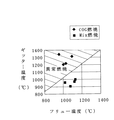
この条件をコークス炉10の全てのフリュー11(フリュー番号を1f〜25fとする)に適用した。
図3に示すように、COGに排ガスを希釈した場合(◆)は、BFGと同じガス供給経路を用いるため、蓄熱室で目地切れ等に伴う洩れ込みによる燃焼が抑制でき、フリュー3f〜23fの範囲で適正な炉壁温度の分布を再現することができ、特に、フリュー群の中央近傍の炉壁温度を安定させることができる。
そして、炭化室12の全体を理想的に加熱することができ、石炭から良好なコークスを製造することができる。
これに対し、富ガスであるCOGのみを燃焼した場合(□)では、従来の図示しないCOG専焼の供給経路を用いるので、両端部の蓄熱室が温度変化が大きくなり目地切れが生じ易く、COGが蓄熱室に洩れて燃焼する。その結果、両端部のフリューの温度が低下する。
COGのみを使用した場合、この両端部のフリューの温度を保証するため、フリューの炉壁温度がフリュー番号3f〜23fの範囲で必要以上に上昇している。
【0011】
また、図4に示すように、従来のCOGの専焼の供給経路を用いた燃焼(◆)で、フリューの温度として1000℃以上を確保した際に、COGのギッター部への洩れ込みの発生による異常燃焼(COGとエアーが燃焼)を生じる斜線領域になり、ギッター温度が上昇し、耐火物の煉瓦が損耗して炉体が損傷したり、時に、爆発的な燃焼になり、耐火煉瓦の破損を招くこともある。
従って、本実施の形態では、フリュー温度を確保しながら異常燃焼を抑制するため、排ガスを混合したいわゆるCOGの濃度を希釈したミックスガス(■)を用いることにより、蓄熱室18に供給(従来のBFG供給経路)した際に、異常燃焼を抑制できる領域にすることができる。
特に、ミックスガス中に含まれる酸素濃度は、6体積%以下にすることにより、確実に蓄熱室18やフリュー11の異常燃焼を防止することができ、安定操業を行うことができる。
酸素濃度が6体積%を超えると、蓄熱室18に供給した際に、蓄熱室18内で異常燃焼し易くなり、前述と同様にギッター温度の上昇等から、耐火煉瓦の損耗、耐火煉瓦の破損等を招く。この理由から酸素濃度を5体積%以下にするとより好ましい結果が得られる。
【0012】
また、A炉とB炉の2基(2炉団)のコークス炉10を用い、A炉とB炉の燃焼切り替えタイミングを10〜20分程度ずれるように調整しておく。
そして、A炉(自炉)の燃焼切り替えの間は、B炉に布設した吸引管から吸引ブロアにより排ガスを取り出し、ミックス用の排ガスとしてA炉に供給することが好ましい。
その結果、COGに混合する排ガスを安定して確保でき、しかも、酸素濃度の低い部分の排ガスを選択して供給できるので、排ガス中の酸素濃度を5重量%以下に低減することが可能となり、異常燃焼の無い安定した操業ができる。
また、フリュー11で燃焼させた後の排ガスは、その温度を90℃以上、好ましくは100℃以上にすることにより、結露が発生する露点以上に維持することができる。
結露の発生を抑制することにより、結露水とSO2 ガスによる強酸の生成を抑制でき、排ガス系路のダクト等が酸腐食するのを防止できる。
しかも、顕熱を保有した排ガスをCOGに混合するため、供給する燃料を節減することができる。
更に、ミックスガスの蓄熱室18への供給は、従来の貧ガス(BFG)の経路をそのまま使用することができる。特に、コークス炉を新設する場合は、ミックスガスとエアーの供給系路のみにすることができるため、コークス炉10の下部(燃料等の供給装置)を簡素化して設置スペースを縮小でき、コークス炉の小型化が可能になる。
【0013】
【実施例】
次に、コークス炉の操業方法の実施例について説明する。
他のコークス炉のフリューで燃焼させた後の120℃の排ガスを吸引管を通して吸引ブロアで取り出して混合装置に供給して、排ガスが74体積%になるようにCOGと混合し、この時の酸素濃度を1.6体積%にしたミックスガス43000Nm3 /hrを蓄熱室で900℃に予熱し、同時に、エアーを蓄熱室に供給して予熱を行い、このミックスガスとエアーをそれぞれ燃焼室に吹き込んで燃焼させ、炭化室の加熱を行った。
そして、蓄熱室のギッターの温度異常の有無、カーボン付着、燃料原単位について調査した。
その結果、ギッターの温度の異常が無く、カーボンの焼き落としが良好でありカーボン付着の発生を抑制できた。
しかも、排ガスの顕熱を有効利用して燃料原単位の低減とダクト等の酸腐食の発生を防止することができた。
これに対し、従来行われている混合ガスを用い、その酸素濃度を考慮しないで蓄熱室を通して燃焼室に供給した場合では、ミックスガスが急速燃焼し、蓄熱室の温度異常が多々発生した。
更に、カーボンの付着やダクト等の酸腐食等が発生しており、操業も不安定になった。
【0014】
以上、本発明の実施の形態を説明したが、本発明は、上記した形態に限定されるものでなく、要旨を逸脱しない条件の変更等は全て本発明の適用範囲である。
例えば、COGに混合する排ガスは、コークス炉の燃焼排ガスの他に、冶金用精錬炉の排ガスや高炉の排ガス、窒素に代表される不活性ガス等を用いることもできる。
更に、ダクト等の酸腐食を防止するため、ダクト等にスラグウール等の断熱材を巻き付けて保温を行い、結露を防止することができる。
【0015】
【発明の効果】
請求項1〜3記載のコークス炉の操業方法は、混合ガスの酸素濃度を6体積%以下にして蓄熱室を通して燃焼室に供給するので、COGを用いた際の燃焼温度を適正化でき、蓄熱室等の耐火物の損傷やカーボンの付着を無くし、乾留したコークスの品質を向上することができる。
更に、排ガスの顕熱を活用して燃料原単位を低減し、しかも、燃料の供給経路を簡素化したコークス炉が実現できる。
【0016】
特に、請求項2記載のコークス炉の操業方法は、富ガスに混合する排ガスを少なくとも2炉団の内の何れか一方から供給するので、混合する排ガスを安定して供給でき、しかも、排ガスに含まれる酸素濃度を低減して操業の安定化を図ることができる。
【0017】
請求項3記載のコークス炉の操業方法は、混合ガスを燃焼室に供給した後の排ガス温度を90℃以上にするので、排ガス中の水分の結露を無くし、ダクト等の酸腐食するのを防止して、設備の長寿命化を図ることができる。
【図面の簡単な説明】
【図1】本発明の一実施の形態に係るコークス炉の操業方法を適用するコークス炉の全体図である。
【図2】同コークス炉の蓄熱室及び燃焼室の断面の模式図である。
【図3】フリュー列と炉壁温度を表すグラフである。
【図4】フリュー温度とギッター温度の関係を表すグラフである。
【符号の説明】
10:コークス炉、11、11a、11b:フリュー(燃焼室)、12:炭化室、13:ミックスガス管、14:アンダーゼット、15:エアー供給管、16:アンダーゼット、17、17a1 、17a2 、17b1 、17b2 :ソールフリュー、18、18a1 18a2 、18b1 、18b2 :蓄熱室、19:水平煙道、20:煙道、21:煙突、22:吸引管、23:調整弁、24:吸引ブロア、25:混合装置、26:本管、27:送給ブロア、28a、28b、29a、29b:供給ダクト[0001]
BACKGROUND OF THE INVENTION
The present invention relates to a method for operating a coke oven, in which exhaust gas from a coke oven is mixed with a rich gas and burned to dry-coal coal.
[0002]
[Prior art]
Conventionally, a coke oven has alternately arranged a carbonization chamber for carbonizing coal and a combustion chamber for heating the carbonization chamber, and fuel preheated through the heat storage chamber is supplied to the combustion chamber for combustion. The coal in the carbonization chamber is carbonized by indirect heating from the combustion chamber. As fuel supplied to the combustion chamber, a poor gas (BFG) that is a blast furnace-generated gas, a rich gas (COG) that is a coke-furnace generated gas, or the like is used.
However, productivity is being improved by consolidating and integrating the steel industry, and the number of steelworks operating one blast furnace is increasing, and the amount of BFG generated tends to decrease.
Therefore, an operation is performed in which combustion exhaust gas (exhaust gas) discharged from a coke oven is mixed with COG and used as fuel for dry distillation.
As a representative example, as described in JP-A-52-52901, for example, a part of combustion exhaust gas discharged through a heat storage chamber is taken out and cooled, and this exhaust gas is converted into BFG or COG. By supplying and recirculating, it is attempted to suppress NOx in the exhaust gas with almost no influence on coke quality and the like.
Further, as described in Japanese Patent Application Laid-Open No. 58-89684, a part of the combustion exhaust gas from the coke oven is taken out and mixed with BFG and COG at a high temperature to form a height direction formed in the combustion chamber. The length of the flame is adjusted to improve the quality of the coke and suppress the increase in the amount of exhaust gas generated.
[0003]
[Problems to be solved by the invention]
However, in the methods described in JP-A-52-52901 and JP-A-58-89684, when COG is used as a fuel for dry distillation, when passing through the heat storage chamber, Cracks or oxygen contained in the exhaust gas causes rapid combustion (abnormal combustion) of COG in the heat storage chamber, the local temperature becomes high, and the brick (gitter) constituting the heat storage chamber is damaged.
In addition, when the ratio of COG used increases, hydrocarbons contained in the COG are decomposed, so that carbon precipitation occurs, and the COG supply route is blocked by the adhesion of the carbon, so that stable coke oven operation is possible. It becomes difficult.
Furthermore, COG supplied to the combustion chamber burns rapidly, and it is easy to form a high-temperature part locally, resulting in non-uniform temperature distribution in the combustion chamber, resulting in wear of refractories and fluctuations in dry distillation of coal. There are problems, such as occurring.
In particular, in the method described in Japanese Patent Laid-Open No. 52-52901, in addition to the above problems, the exhaust gas is cooled and then mixed, so that the sensible heat of the exhaust gas cannot be used effectively and is required for dry distillation. There is a problem that the amount of heat increases and the unit consumption of fuel increases.
[0004]
The present invention has been made in view of such circumstances, and provides a method for operating a coke oven that can suppress rapid combustion of COG and adhesion of carbon, and can effectively utilize sensible heat of exhaust gas to reduce fuel consumption. The purpose is to provide.
[0005]
[Means for Solving the Problems]
The coke oven operating method of the present invention that meets the above-mentioned object is the coke supplied to the combustion chamber through the heat storage chamber after mixing a part of the exhaust gas discharged through the heat storage chamber of the coke oven with a rich gas to make a mixed gas. In the operation method of the furnace, the oxygen concentration of the mixed gas is set to 6% by volume or less.
By this method, the oxygen concentration of the mixed gas is kept within a predetermined range, so when passing through the heat storage chamber, leakage from brick joints and cracks, or local combustion of rich gas (COG) due to the oxygen concentration of the exhaust gas. Moreover, since the gas supply path when using poor gas is used as it is, the ideal combustion state of COG when supplied to the combustion chamber can be reproduced, and the temperature of the combustion chamber can be made uniform. it can.
Furthermore, it is possible to prevent C (carbon) produced by the decomposition of CH 4 in the high temperature portion of the heat storage chamber from adhering and blocking the supply path.
When the oxygen concentration is higher than 6% by volume, rapid combustion of COG occurs, and the local temperature rises, adversely affecting the refractory damage and the quality of coke that has been carbonized. However, if the temperature is extremely low, the burned-out carbon is deteriorated. Therefore, a preferable result can be obtained by setting the oxygen concentration to 0.5 to 5% by volume.
[0006]
Here, the coke oven may be at least two furnace groups, and the exhaust gas mixed with the rich gas may be supplied from any one of the coke ovens.
Thereby, generation | occurrence | production of combustion exhaust gas by the stop of operation can be prevented, and mixed gas can be supplied stably.
Furthermore, by operating the combustion chamber switching time (combustion cycle) in each furnace group with a shift of 5 to 30 minutes, the exhaust gas of the other furnace can be supplied for mixing when the own furnace is switched. The supply concentration and the oxygen concentration mixed in from the exhaust gas can be stably reduced.
[0007]
Furthermore, it is preferable that the exhaust gas temperature after supplying the mixed gas to the combustion chamber is 90 ° C. or higher.
The exhaust gas temperature is maintained at a temperature equal to or higher than the dew point to eliminate the condensation of moisture in the exhaust gas, and the generation of strong acid due to the absorption of the SO 2 gas by the condensed water can be suppressed, thereby preventing the duct or the like from acid corrosion.
When the exhaust gas temperature is lower than 90 ° C., SO 2 gas is absorbed by the suddenly generated dew condensation and strong acid is generated, and corrosion of ducts and the like proceeds rapidly by this strong acid.
[0008]
DETAILED DESCRIPTION OF THE INVENTION
Next, embodiments of the present invention will be described with reference to the accompanying drawings for understanding of the present invention.
FIG. 1 is an overall view of a coke oven applied to a method of operating a coke oven according to an embodiment of the present invention, FIG. 2 is a schematic view of a cross section of a heat storage chamber and a combustion chamber of the coke oven, and FIG. FIG. 4 is a graph showing the relationship between the flue temperature, the jitter temperature, and abnormal combustion.
As shown in FIG. 1, a
The flue 11 is supplied with the mixed gas (mixed gas) and air to the sole flue 17 through the
A
The exhaust gas after burning in the flue 11 is drawn down to the
Then, COG (rich gas which is coke oven generated gas) is sent from the
[0009]
Next, the gas flow path will be described in detail with reference to FIG.
The mixed gas in which the exhaust gas and COG are mixed passes through the sole flue 17a 1 (17a 2 ) from an
The air is supplied to the high-temperature heat storage chamber 18b 1 (18b 2 ) through the sole flue 17b 1 (17b 2 ) from the Andasuit 16 connected to the
The preheated mixed gas and air are blown into the flue 11a (11b) through the
The exhaust gas after burning in the flue 11a is exhausted from the
The preheating of the mixed gas and air and the heat replacement (heating) of the brick brick with the exhaust gas are normally switched between the heat storage chambers 18a 1 and 18b 1 and the heat storage chambers 18a 2 and 18b 2 within a predetermined time of 20 to 30 minutes. It is performed alternately while performing.
[0010]
Next, a method for operating the coke oven using the
High-calorie COG of about 4300 Kcal / Nm 3 mainly composed of CO, CH 4 (hydrocarbon), etc., generated when carbon is carbonized in the
The mix gas is supplied to the heat storage chamber 18a 1 through the sole flue 17a 1 from the
The air is supplied to the high-temperature heat storage chamber 18b 1 through the sole flue 17b 1 from the
The preheated mixed gas and air were blown into the flue 11a through the
This condition was applied to all the flues 11 of the coke oven 10 (with flu numbers 1f to 25f).
As shown in FIG. 3, when exhaust gas is diluted in COG (♦), the same gas supply path as BFG is used, so that combustion due to leakage due to joint breakage or the like in the heat storage chamber can be suppressed, and
And the
On the other hand, when only COG, which is a rich gas, is burned (□), a conventional COG-only-fired supply path (not shown) is used. Leaks into the heat storage chamber and burns. As a result, the temperature of the flue at both ends is lowered.
When only COG is used, the temperature of the flue wall rises more than necessary in the range of
[0011]
Also, as shown in FIG. 4, when combustion using the conventional COG mono-combustion supply path (♦) is secured at a temperature of 1000 ° C. or more as the temperature of the flue, the COG leaks into the jitter part. It becomes a shaded area where abnormal combustion (COG and air combustion) occurs, the temperature of the glitter rises, the refractory brick wears down and the furnace body is damaged, and sometimes it becomes explosive combustion and the refractory brick breaks May be invited.
Therefore, in the present embodiment, in order to suppress abnormal combustion while ensuring the flue temperature, the mixed gas (■) in which the concentration of so-called COG mixed with exhaust gas is diluted is used to supply the heat storage chamber 18 (conventional). When the BFG supply path), it is possible to make the region in which abnormal combustion can be suppressed.
In particular, by setting the oxygen concentration contained in the mixed gas to 6% by volume or less, abnormal combustion of the
When the oxygen concentration exceeds 6% by volume, when supplied to the
[0012]
Moreover, the
And during combustion switching of A furnace (own furnace), it is preferable to take out exhaust gas with the suction blower from the suction pipe laid in B furnace, and to supply to A furnace as exhaust gas for mixing.
As a result, the exhaust gas to be mixed with COG can be stably secured, and furthermore, the exhaust gas with a low oxygen concentration can be selected and supplied, so that the oxygen concentration in the exhaust gas can be reduced to 5% by weight or less, Stable operation without abnormal combustion is possible.
Further, the exhaust gas after being burned by the flue 11 can be maintained at a temperature equal to or higher than the dew point at which condensation occurs by setting the temperature to 90 ° C. or higher, preferably 100 ° C. or higher.
By suppressing the occurrence of dew condensation, it is possible to suppress the formation of strong acid by dew condensation water and SO 2 gas, and it is possible to prevent acid corrosion of the ducts of the exhaust gas system.
In addition, since the exhaust gas having sensible heat is mixed with the COG, fuel to be supplied can be saved.
Furthermore, the supply of the mixed gas to the
[0013]
【Example】
Next, an embodiment of a method for operating a coke oven will be described.
The exhaust gas at 120 ° C. after being burned in the flue of another coke oven is taken out with a suction blower through a suction pipe and supplied to a mixing device, mixed with COG so that the exhaust gas becomes 74% by volume, and oxygen at this time Mix gas 43000Nm 3 / hr with a concentration of 1.6% by volume is preheated to 900 ° C in the heat storage chamber, and at the same time, air is supplied to the heat storage chamber for preheating, and the mix gas and air are blown into the combustion chamber. And the carbonization chamber was heated.
And we investigated the presence or absence of temperature abnormality in the heat storage chamber, carbon adhesion, and fuel intensity.
As a result, there was no abnormality in the temperature of the glitter, the carbon burned out well, and the occurrence of carbon adhesion could be suppressed.
In addition, the sensible heat of the exhaust gas can be effectively used to reduce the fuel consumption rate and to prevent the occurrence of acid corrosion of the duct and the like.
On the other hand, when a conventional mixed gas was used and supplied to the combustion chamber through the heat storage chamber without considering its oxygen concentration, the mixed gas burned rapidly, resulting in many temperature abnormalities in the heat storage chamber.
Furthermore, carbon adhesion, acid corrosion of ducts, etc. occurred, and the operation became unstable.
[0014]
Although the embodiments of the present invention have been described above, the present invention is not limited to the above-described embodiments, and all changes in conditions and the like that do not depart from the gist are within the scope of the present invention.
For example, as the exhaust gas mixed with the COG, in addition to the combustion exhaust gas of the coke oven, exhaust gas of a metallurgical refining furnace, exhaust gas of a blast furnace, an inert gas typified by nitrogen, or the like can be used.
Furthermore, in order to prevent acid corrosion of the duct or the like, heat insulation can be performed by wrapping a duct or the like with a heat insulating material such as slag wool, thereby preventing condensation.
[0015]
【The invention's effect】
In the method for operating a coke oven according to
Further, a coke oven can be realized in which the sensible heat of exhaust gas is utilized to reduce the fuel consumption rate and the fuel supply path is simplified.
[0016]
In particular, in the method of operating a coke oven according to claim 2, since the exhaust gas to be mixed with the rich gas is supplied from at least one of the two furnace groups, the exhaust gas to be mixed can be stably supplied, and the exhaust gas can be supplied to the exhaust gas. It is possible to stabilize the operation by reducing the oxygen concentration contained.
[0017]
In the method of operating a coke oven according to
[Brief description of the drawings]
FIG. 1 is a general view of a coke oven to which a coke oven operating method according to an embodiment of the present invention is applied.
FIG. 2 is a schematic view of a cross section of a heat storage chamber and a combustion chamber of the coke oven.
FIG. 3 is a graph showing a flue train and a furnace wall temperature.
FIG. 4 is a graph showing the relationship between the flue temperature and the jitter temperature.
[Explanation of symbols]
10: coke oven, 11, 11a, 11b: flues (combustion chamber), 12: carbonizing chamber, 13: Mixed gas pipe, 14: under-jet, 15: air supply tube, 16: under-jet, 17, 17a 1, 17a 2 , 17 b 1 , 17 b 2 : Sole Flue, 18, 18 a 1 18 a 2 , 18 b 1 , 18 b 2 : Thermal storage chamber, 19: Horizontal flue, 20: Chimney, 21: Chimney, 22: Suction pipe, 23: Adjustment Valve: 24: Suction blower, 25: Mixing device, 26: Main pipe, 27: Feeding blower, 28a, 28b, 29a, 29b: Supply duct
Claims (3)
Priority Applications (1)
| Application Number | Priority Date | Filing Date | Title |
|---|---|---|---|
| JP2000202332A JP4246355B2 (en) | 2000-07-04 | 2000-07-04 | Coke oven operation method |
Applications Claiming Priority (1)
| Application Number | Priority Date | Filing Date | Title |
|---|---|---|---|
| JP2000202332A JP4246355B2 (en) | 2000-07-04 | 2000-07-04 | Coke oven operation method |
Publications (2)
| Publication Number | Publication Date |
|---|---|
| JP2002020757A JP2002020757A (en) | 2002-01-23 |
| JP4246355B2 true JP4246355B2 (en) | 2009-04-02 |
Family
ID=18699866
Family Applications (1)
| Application Number | Title | Priority Date | Filing Date |
|---|---|---|---|
| JP2000202332A Expired - Fee Related JP4246355B2 (en) | 2000-07-04 | 2000-07-04 | Coke oven operation method |
Country Status (1)
| Country | Link |
|---|---|
| JP (1) | JP4246355B2 (en) |
Families Citing this family (1)
| Publication number | Priority date | Publication date | Assignee | Title |
|---|---|---|---|---|
| KR100936828B1 (en) | 2007-12-13 | 2010-01-14 | 박종희 | Functional material enhanced egg and producing method thereof |
-
2000
- 2000-07-04 JP JP2000202332A patent/JP4246355B2/en not_active Expired - Fee Related
Also Published As
| Publication number | Publication date |
|---|---|
| JP2002020757A (en) | 2002-01-23 |
Similar Documents
| Publication | Publication Date | Title |
|---|---|---|
| EP0987508B1 (en) | Firing system for counter-current mineral calcinating processes | |
| TWI470073B (en) | Method for reducing nitrogen oxides from the waste gas of a coke oven | |
| JP4355748B2 (en) | Method for producing iron ore pellets | |
| JP2010513181A (en) | Glass melting furnace | |
| US20120006668A1 (en) | Coking plant with flue gas recirculation | |
| KR100971258B1 (en) | Apparatus for supplying gas into a combustion chamber of coke oven | |
| JP4246355B2 (en) | Coke oven operation method | |
| EP2460869A1 (en) | Process for producing ferro coke | |
| WO2020203629A1 (en) | Method and apparatus for producing quick lime using coke dry quenching facility | |
| KR101751069B1 (en) | Method for combustion of a low-grade fuel | |
| KR100761211B1 (en) | A partial combustion burner for preheating oxygen | |
| US20230106711A1 (en) | Method for burning carbon-containing material in a pfr shaft furnace | |
| JP2003342582A (en) | Method for burning gas in coke oven | |
| JP2012167156A (en) | Method and apparatus for producing ferrocoke | |
| NO165407B (en) | PROCEDURE FOR DIRECT REDUCTION OF IRON-OX SUSTAINABLE MATERIALS FOR IRON FUNGI IN TURNOVER OVEN. | |
| JPH06184540A (en) | Process for producing coke and equipment therefor | |
| RU2079079C1 (en) | Method and shaft furnace for roasting of lump materials | |
| JP3439242B2 (en) | Coke production method | |
| JP3838379B2 (en) | Method for promoting dry distillation of coke oven kiln | |
| SU996817A1 (en) | Double-bath steel melting furnace | |
| JP2002220591A (en) | Coke dry quenching facility and method for operating the same | |
| CN116026138A (en) | Heat accumulating type double-hearth rotary kiln | |
| JPH03148510A (en) | Ceramic burner for coke furnace end flue | |
| KR20120132373A (en) | Heating apparatus | |
| JPH07113079A (en) | Carbonization promoting method for coking, coking process and oven door of coke oven |
Legal Events
| Date | Code | Title | Description |
|---|---|---|---|
| A621 | Written request for application examination |
Free format text: JAPANESE INTERMEDIATE CODE: A621 Effective date: 20060905 |
|
| TRDD | Decision of grant or rejection written | ||
| A01 | Written decision to grant a patent or to grant a registration (utility model) |
Free format text: JAPANESE INTERMEDIATE CODE: A01 Effective date: 20081216 |
|
| A01 | Written decision to grant a patent or to grant a registration (utility model) |
Free format text: JAPANESE INTERMEDIATE CODE: A01 |
|
| A61 | First payment of annual fees (during grant procedure) |
Free format text: JAPANESE INTERMEDIATE CODE: A61 Effective date: 20090108 |
|
| R151 | Written notification of patent or utility model registration |
Ref document number: 4246355 Country of ref document: JP Free format text: JAPANESE INTERMEDIATE CODE: R151 |
|
| FPAY | Renewal fee payment (event date is renewal date of database) |
Free format text: PAYMENT UNTIL: 20120116 Year of fee payment: 3 |
|
| FPAY | Renewal fee payment (event date is renewal date of database) |
Free format text: PAYMENT UNTIL: 20130116 Year of fee payment: 4 |
|
| FPAY | Renewal fee payment (event date is renewal date of database) |
Free format text: PAYMENT UNTIL: 20130116 Year of fee payment: 4 |
|
| S531 | Written request for registration of change of domicile |
Free format text: JAPANESE INTERMEDIATE CODE: R313531 |
|
| FPAY | Renewal fee payment (event date is renewal date of database) |
Free format text: PAYMENT UNTIL: 20130116 Year of fee payment: 4 |
|
| R350 | Written notification of registration of transfer |
Free format text: JAPANESE INTERMEDIATE CODE: R350 |
|
| FPAY | Renewal fee payment (event date is renewal date of database) |
Free format text: PAYMENT UNTIL: 20130116 Year of fee payment: 4 |
|
| S533 | Written request for registration of change of name |
Free format text: JAPANESE INTERMEDIATE CODE: R313533 |
|
| FPAY | Renewal fee payment (event date is renewal date of database) |
Free format text: PAYMENT UNTIL: 20130116 Year of fee payment: 4 |
|
| R350 | Written notification of registration of transfer |
Free format text: JAPANESE INTERMEDIATE CODE: R350 |
|
| FPAY | Renewal fee payment (event date is renewal date of database) |
Free format text: PAYMENT UNTIL: 20140116 Year of fee payment: 5 |
|
| S533 | Written request for registration of change of name |
Free format text: JAPANESE INTERMEDIATE CODE: R313533 |
|
| R350 | Written notification of registration of transfer |
Free format text: JAPANESE INTERMEDIATE CODE: R350 |
|
| LAPS | Cancellation because of no payment of annual fees |