JP4243003B2 - Packing structure for moisture-curing sealant - Google Patents
Packing structure for moisture-curing sealant Download PDFInfo
- Publication number
- JP4243003B2 JP4243003B2 JP2000131553A JP2000131553A JP4243003B2 JP 4243003 B2 JP4243003 B2 JP 4243003B2 JP 2000131553 A JP2000131553 A JP 2000131553A JP 2000131553 A JP2000131553 A JP 2000131553A JP 4243003 B2 JP4243003 B2 JP 4243003B2
- Authority
- JP
- Japan
- Prior art keywords
- bag
- drum
- moisture
- curing
- sealant
- Prior art date
- Legal status (The legal status is an assumption and is not a legal conclusion. Google has not performed a legal analysis and makes no representation as to the accuracy of the status listed.)
- Expired - Fee Related
Links
Images


Landscapes
- Closures For Containers (AREA)
- Packages (AREA)
Description
【0001】
【発明の属する技術分野】
本発明は、有底円筒状であるドラム缶の内周面および底面に接触する合成樹脂製の袋状部材が前記ドラム缶内に挿脱可能に装着され、前記袋状部材の内周面に直接もしくは間接に摺接する押圧部材を前記袋状部材内に挿入することによって押し出される湿気硬化型シール剤が、前記袋状部材で直接もしくは間接に覆われるようにしてドラム缶内に収容される湿気硬化型シール剤の充填包装構造に関する。
【0002】
【従来の技術】
従来、特開平6−171601号および特開平8−244845号公報等で開示されるように、ドラム缶を再利用するにあたってドラム缶の内面がシール剤で汚れてしまうことを防止するために、合成樹脂から成る袋状部材をドラム缶内に着脱可能に装着し、その袋状部材内に湿気硬化型シール剤を直接もしくは間接に収納する手法が既に実施されている。
【0003】
【発明が解決しようとする課題】
ところで、前記袋状部材および湿気硬化型シール剤を収納したドラム缶の搬送時には、該ドラム缶の上端開口部を開閉可能な蓋部材で気密に閉じておく必要がある。このため従来では、ドラム缶の上端開口縁の全周にシール剤を塗布し、そのシール剤をドラム缶との間に挟むようにして、蓋部材でドラム缶の上端開口部を閉じるようにしている。しかるにシール剤がドラム缶の上端開口縁および蓋部材の内面に付着するので、ドラム缶および蓋部材の再利用にあたっては付着したシール剤を除去する作業が必要となり、面倒である。
【0004】
本発明は、かかる事情に鑑みてなされたものであり、ドラム缶および蓋部材の再利用にあたって面倒な作業を必要としないようにして、袋状部材および湿気硬化型シール剤をドラム缶内に気密に収容し得るようにした湿気硬化型シール剤の充填包装構造を提供することを目的とする。
【0005】
【課題を解決するための手段】
上記目的を達成するために、請求項1記載の発明は、有底円筒状であるドラム缶の内周面および底面に接触する合成樹脂製の袋状部材が前記ドラム缶内に挿脱可能に装着され、前記袋状部材の内周面に直接もしくは間接に摺接する押圧部材を前記袋状部材内に挿入することによって押し出される湿気硬化型シール剤が、前記袋状部材で直接もしくは間接に覆われるようにしてドラム缶内に収容される湿気硬化型シール剤の充填包装構造であって、ドラム缶の開口縁と、該ドラム缶の上端開口部を開閉可能に閉じる蓋部材との間に、前記袋状部材の開口部全周に連なってドラム缶の上端開口縁全周に接触するリップ部と、該リップ部にリング状に塗布される湿気硬化型シール剤と、切り開くことを可能として前記袋状部材の開口部を覆う合成樹脂製のシートの外周部とが挟持されることを特徴とする。
【0006】
このような構成によれば、蓋部材でドラム缶の上端開口部を閉じたときに、袋状部材に連なるリップ部と、袋状部材の開口部を覆うシートとの間に湿気硬化型シール剤が介在することにより袋状部材内が気密に保持され、袋状部材で直接もしくは間接に覆われる湿気硬化型シール剤に湿気が作用することが確実に防止される。またシートは切り開き可能であり、蓋部材を開放した状態でシートを切り開くことによる押圧部材を袋状部材内に挿入して湿気硬化型シール剤を押し出すことができる。この際、押圧部材が袋状部材の内周面に直接もしくは間接に摺接することによって袋状部材にはドラム缶内に引き込まれる方向の摩擦力が作用するが、蓋部材を閉じたときにシートおよびリップ部間に介在した湿気硬化型シール剤が硬化することにより該シール剤の近傍でリップ部がドラム缶の上端開口縁に引っ掛かるように硬化して、袋状部材がドラム缶内に引き込まれることが防止される。しかも湿気硬化型シール剤を押し出した後でに袋状部材をドラム缶から離脱せしめると、ドラム缶の内周面および底面には湿気硬化型シール剤が付着しておらず、さらにドラム缶の上端開口縁および蓋部材の内面にも湿気硬化型シール剤が付着していないので、湿気硬化型シール剤を除去するための面倒な作業を不要として、ドラム缶および蓋部材を再利用することができる。
【0007】
また請求項2記載の発明は、上記請求項1記載の発明の構成に加えて、前記袋状部材に前記リップ部が一体に形成されることを特徴とし、かかる構成によれば、袋状部材およびリップ部を低コストで形成することができる。
【0008】
さらに請求項3記載の発明は、上記請求項1または2記載の発明の構成に加えて、前記袋状部材内に湿気硬化型シール剤が直接充填され、前記押圧部材の外周および前記袋状部材の内周間に介在し得る円筒部を一体に有して合成樹脂により形成される内蓋と、前記円筒部を袋状部材の内周に圧接させるばね力を発揮することを可能として内蓋に着脱可能に装着されるばねとが、前記ドラム缶内に挿入されることを特徴とし、かかる構成によれば、ドラム缶の再利用にあたって廃棄処分しなければならない部品重量を低減することができる。すなわち袋状部材内に収納される内袋に湿気硬化型シール剤を充填するようにしたものでは袋状部材および内袋を廃棄しなければならないが、湿気硬化型シール剤を袋状部材内に直接充填するので、袋状部材および内蓋を廃棄すればよく、廃棄処分重量を低減することができる。
【0009】
【発明の実施の形態】
以下、本発明の実施の形態を、添付の図面に示した本発明の実施例に基づいて説明する。
【0010】
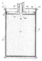
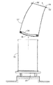
図1〜図9は本発明の第1実施例を示すものであり、図1はシール剤を充填して閉じた状態でのドラム缶の縦断面図、図2は袋状部材の斜視図、図3は内蓋の斜視図、図4は図1の4矢示部拡大図、図5は押圧部材によるシール剤の押出しを開始した状態を示す縦断面図、図6は図5の要部拡大図、図7は押圧部材によるシール剤の押出し完了状態での図5に対応した縦断面図、図8は押圧部材を抜き出した状態での図5に対応した縦断面図、図9はドラム缶から袋状部材を離脱せしめた状態でのドラム缶の縦断面図である。
【0011】
先ず図1において、有底円筒状であるドラム缶15内には、たとえば車両のウインド周縁部をシールするための湿気硬化型シール剤16が、外気との接触を回避した気密状態で充填包装されており、その気密状態を保持したままドラム缶15は所望の位置まで搬送される。
【0012】
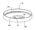
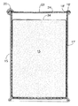
図2を併せて参照して、ドラム缶15内には、該ドラム缶15の内周面および底面に接触する合成樹脂製の袋状部材17が挿脱可能に装着されるものであり、この袋状部材17は、たとえば2枚の矩形状であるシート状体の両側縁部および底部を熱融着することにより形成される。而して袋状部材17は、湿気を透過しない合成樹脂により形成される必要があり、たとえばポリオレフィン系の合成樹脂にアルミ製の膜が積層されて成るアルミラミネートフィルムを好適に用いることができる。
【0013】
袋状部材17の開口部全周には、該袋状部材17と同一材料によりラッパ状に形成されるリップ部18が、たとえば熱融着により連設される。而して該リップ部18は、袋状部材17のドラム缶15への装着により、ドラム缶15の上端開口縁全周に接触して該ドラム缶15から外方にはみ出すように形成される。
【0014】
図3を併せて参照して、湿気硬化型シール剤16は前記袋状部材17で直接覆われるようにして袋状部材17内に直接充填されるのであるが、この湿気硬化型シール剤16の上面に接触する内蓋19が袋状部材17内に挿入される。
【0015】
内蓋19は、円板状の平板部19aと、該平板部19aの外周に連なる円筒部19bとを一体に有して、前記袋状部材17およびリップ部18と同一材料により形成されるものであり、平板部19aの中央部に、着脱可能なシールリップ21で閉じられる円形の開口部20が設けられる。
【0016】
この内蓋19は、円筒部19bの外周をドラム缶15内における袋状部材17の内周に接触させるようにして該袋状部材17に挿入されるものであり、該円筒部19bを袋状部材17の内周に圧接させるばね力を発揮するばね22が、内蓋19に着脱可能に装着される。
【0017】
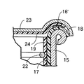
図4を併せて参照して、ドラム缶15の上端開口部は、フック26でドラム缶15との連結状態を維持する蓋部材23で開閉可能に閉じられるものであり、ドラム缶15の開口縁および蓋部材23間には、袋状部材17の開口部全周に連なってドラム缶15の開口縁全周に接触する前記リップ部18と、該リップ部18の上面にリング状に塗布される湿気硬化型シール剤16′と、袋状部材17の開口部を覆うシート24の外周部とが挟持される。
【0018】
シート24は、切り開くことを可能として、前記袋状部材17、リップ部18および内蓋19と同一材料により形成される。
【0019】
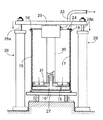
湿気硬化型シール剤16が充填包装されたドラム缶15は、図5で示すように、たとえば台車27によって所定の位置まで搬送され、その所定位置には、湿気硬化型シール剤16をドラム缶15から押し出すための押圧部材31が昇降作動を可能として配置される。
【0020】
前記所定位置における台車27の両側には、鉛直軸線を有するシリンダ28,28が固定配置されており、それらのシリンダ28,28から上方に延びるピストンロッド28a,28aの上端が連結部材29で相互に連結される。この連結部材29の中央部から垂下される排出管30の下端に、該排出管30内に通じる連通孔32を中央部に有して円盤状に形成される押圧部材31が固着される。また排出管30の上部には湿気硬化型シール剤16を導く導管33が接続されている。
【0021】
ドラム缶15内の湿気硬化型シール剤16を押圧部材31で押し出す際には、図6で明示するように、蓋部材23を開放するとともに、湿気硬化型シール剤16′に対応する部分をリング状に残してシート24の中央部を鎖線で示す無端状のラインLに沿ってカッタ等で切り開き、内蓋19からシールリップ21を離脱せしめた状態で、外周部に図示しないグリスを塗布した押圧部材31を内蓋19内に挿入する。而してシリンダ28,28を縮少作動せしめることにより、押圧部材31は、その押圧部材31の外周および袋状部材17の内周間に内蓋19に円筒部19bを挟んだ状態で、湿気硬化型シール剤16に圧力を加えるように降下する。
【0022】
押圧部材31の降下に応じて湿気硬化型シール剤16は、内蓋19の開口部20、押圧部材31の連通孔32、排出管30および導管33を介して押し出される。
【0023】
図7で示すように、ドラム缶15内の湿気硬化型シール剤16が、たとえば満杯時の95%まで押し出されたときには、排出管30および導管33に空気が混入してしまうことを回避するために押圧部材31の降下作動すなわちシリンダ28,28の収縮作動は、湿気硬化型シール剤16の押出しが完了したものとして停止される。
【0024】
湿気硬化型シール剤16の押出完了後には、図8で示すように、シリンダ28,28が伸長作動し、押圧部材31はドラム缶15内から上方に離脱するように上昇し、ドラム缶15は、台車27により次の所定位置まで搬送される。
【0025】
而して台車27上のドラム缶15内からは、図9で示すように、湿気硬化型シール剤16がわずかに残った袋状部材17と、ばね22で袋状部材17に押し付けられた内蓋19とが、廃棄物として取り出される。
【0026】
次にこの第1実施例の作用について説明すると、湿気硬化型シール剤16をドラム缶15内に気密に充填包装するにあたっては、ドラム缶15の上端開口縁と、該ドラム缶15の上端開口部を開閉可能に閉じる蓋部材23との間に、袋状部材17の開口部全周に連なってドラム缶15の開口縁全周に接触するリップ部18と、該リップ部18にリング状に塗布される湿気硬化型シール剤16′と、切り開くことを可能として袋状部材17の開口部を覆う合成樹脂製のシート24の外周部とが挟持される。
【0027】
したがって蓋部材23でドラム缶15の上端開口部を閉じたときには、袋状部材17に連なるリップ部18と、袋状部材17の開口部を覆うシート24との間に、湿気に接触して硬化するシール剤16′が接着剤として介在することにより袋状部材17内が気密に保持され、袋状部材17で直接に覆われる前記シール剤16に湿気が作用することが確実に防止される。
【0028】
またシート24は切り開き可能であり、蓋部材23を開放した状態でシート24を切り開くことによる押圧部材31を袋状部材17内に挿入して前記シール剤16を押し出すことができる。この際、押圧部材31が袋状部材17の内周面に内蓋19の円筒部19bを介して間接に摺接することによって、袋状部材17にはドラム缶15内に引き込まれる方向の摩擦力が作用する。しかるに蓋部材23を閉じたときにシート24およびリップ部18間に介在したシール剤16′が硬化することにより、該シール剤16′の近傍でリップ部18がドラム缶15の上端開口縁に引っ掛かるように硬化して、袋状部材17がドラム缶15内に引き込まれることが防止される。
【0029】
しかも湿気硬化型シール剤16を押し出した後で袋状部材17をドラム缶15から離脱せしめると、ドラム缶15の内周面および底面には前記シール剤16が付着しておらず、さらにドラム缶15の上端開口縁および蓋部材23の内面にも前記シール剤16が付着していないので、前記シール剤16を除去するための面倒な作業を不要として、ドラム缶15および蓋部材23を再利用することができる。
【0030】
さらに袋状部材17内に湿気硬化型シール剤16が直接充填され、押圧部材31の外周および袋状部材17の内周間に介在し得る円筒部19bを一体に有する合成樹脂製の内蓋19と、円筒部19bを袋状部材17の内周に圧接させるばね力を発揮して内蓋19に着脱可能に装着されるばね22とが、ドラム缶15内に挿入されており、ドラム缶15の再利用にあたって廃棄処分しなければならない部品重量を低減することができる。すなわち袋状部材17内に収納される内袋にシール剤16を充填するようにしたもの(後述の第2実施例参照)では袋状部材17および内袋を廃棄しなければならないが、シール剤16を袋状部材17内に直接充填するので、袋状部材17および内蓋19を廃棄すればよく、廃棄処分重量を低減することができる。
【0031】
図10〜図12は本発明の第2実施例を示すものであり、図10はシール剤を充填して閉じた状態でのドラム缶の縦断面図、図11は押圧部材によるシール剤の押出しを開始した状態を示す縦断面図、図12はドラム缶から袋状部材を離脱せしめた状態でのドラム缶の縦断面図である。
【0032】
ドラム缶15内には、該ドラム缶15の内周面および底面に接触する合成樹脂製の袋状部材17′が挿脱可能に装着されるものであり、該袋状部材17′の開口部全周には、ドラム缶15の上端開口縁全周に接触して該ドラム缶15から外方にはみ出すリップ部18′が一体に形成される。
【0033】
湿気硬化型シール剤16は、袋状部材17′内に収容される内袋34に気密に収容されており、内袋34を介して袋状部材17′で間接的に覆われる。
【0034】
ドラム缶15の上端開口部を気密に閉じるにあたっては、上述の第1実施例と同様に、ドラム缶15の開口縁および蓋部材23間に、袋状部材17′の開口部全周に連なってドラム缶15の開口縁全周に接触する前記リップ部18′と、該リップ部18′の上面にリング状に塗布される湿気硬化型シール剤16′と、袋状部材17′の開口部を覆うシート24の外周部とが挟持される。
【0035】
ドラム缶15内の湿気硬化型シール剤16を押圧部材31で押し出す際には、図11で示すように、蓋部材23を開放するとともに、湿気硬化型シール剤16′に対応する部分をリング状に残してシート24の中央部を鎖線で示す無端状のラインLに沿ってカッタ等で切り開き、内袋34の上部中央部を開口部34aとして切欠いた状態で、押圧部材31を袋状部材17′内に挿入するが、押圧部材31の外周にはOリング35,35が装着されている。
【0036】
而して押圧部材31は、Oリング35,35を介して袋状部材17′の内周に摺接するようにして湿気硬化型シール剤16に圧力を加えるように降下し、この押圧部材31の降下に応じて湿気硬化型シール剤16は、内袋34の開口部34a、押圧部材31の連通孔32、排出管30および導管33を介して押し出される。
【0037】
ドラム缶15内の湿気硬化型シール剤16が所定量押し出された押出完了後には、図12で示すように、湿気硬化型シール剤16がわずかに残った袋状部材17′と、該袋状部材17′内に収容された内袋34とが、廃棄物として取り出される。
【0038】
この第2実施例によれば、廃棄処分量が上記第1実施例に比べて多くなるが、袋状部材17′にリップ部18′が一体に形成されているので、袋状部材17′およびリップ部18′を低コストで形成することができる。
【0039】
以上、本発明の実施例を説明したが、本発明は上記実施例に限定されるものではなく、特許請求の範囲に記載された本発明を逸脱することなく種々の設計変更を行うことが可能である。
【0040】
【発明の効果】
以上のように請求項1記載の発明によれば、湿気硬化型シール剤に湿気が作用することを確実に防止して袋状部材および湿気硬化型シール剤をドラム缶内に気密に収容することを可能としつつ、押圧部材を袋状部材内に挿入して湿気硬化型シール剤を押し出す際に袋状部材がドラム缶内に引き込まれることを防止することができ、しかも湿気硬化型シール剤を除去するための面倒な作業を不要として、ドラム缶および蓋部材を再利用することができる。
【0041】
また請求項2記載の発明によれば、袋状部材およびリップ部を低コストで形成することができる。
【0042】
さらに請求項3記載の発明によれば、ドラム缶の再利用にあたって廃棄処分しなければならない部品重量を低減することができる。
【図面の簡単な説明】
【図1】第1実施例を示すものであってシール剤を充填して閉じた状態でのドラム缶の縦断面図である。
【図2】袋状部材の斜視図である。
【図3】内蓋の斜視図である。
【図4】図1の4矢示部拡大図である。
【図5】押圧部材によるシール剤の押出しを開始した状態を示す縦断面図である。
【図6】図5の要部拡大図である。
【図7】押圧部材によるシール剤の押出し完了状態での図5に対応した縦断面図である。
【図8】押圧部材を抜き出した状態での図5に対応した縦断面図である。
【図9】ドラム缶から袋状部材を離脱せしめた状態でのドラム缶の縦断面図である。
【図10】第2実施例を示すものであってシール剤を充填して閉じた状態でのドラム缶の縦断面図である。
【図11】押圧部材によるシール剤の押出しを開始した状態を示す縦断面図である。
【図12】ドラム缶から袋状部材を離脱せしめた状態でのドラム缶の縦断面図である。
【符号の説明】
15・・・ドラム缶
16,16′・・・湿気硬化型シール剤
17,17′・・・袋状部材
18,18′・・・リップ部
19・・・内蓋
19b・・・円筒部
22・・・ばね
23・・・蓋部材
24・・・シート
31・・・押圧部材[0001]
BACKGROUND OF THE INVENTION
In the present invention, a bag-shaped member made of a synthetic resin that comes into contact with the inner peripheral surface and the bottom surface of a drum can having a bottomed cylindrical shape is removably mounted in the drum can, and is directly or directly on the inner peripheral surface of the bag-shaped member. A moisture-curing seal that is contained in a drum can so that the moisture-curing sealant that is pushed out by inserting a pressing member that is in sliding contact with the bag-shaped member is covered directly or indirectly with the bag-shaped member. The present invention relates to an agent filling and packaging structure.
[0002]
[Prior art]
Conventionally, as disclosed in JP-A-6-171601 and JP-A-8-244845, in order to prevent the inner surface of a drum can from being contaminated with a sealant when the drum can is reused, a synthetic resin is used. A method has been already implemented in which a bag-shaped member is detachably mounted in a drum can and a moisture-curing sealant is directly or indirectly stored in the bag-shaped member.
[0003]
[Problems to be solved by the invention]
By the way, when the drum can containing the bag-like member and the moisture-curing sealant is transported, the upper end opening of the drum can needs to be airtightly closed with a lid member that can be opened and closed. For this reason, conventionally, a sealing agent is applied to the entire circumference of the upper end opening edge of the drum can, and the sealing agent is sandwiched between the drum can and the upper end opening of the drum can is closed by a lid member. However, since the sealing agent adheres to the upper end opening edge of the drum can and the inner surface of the lid member, the reuse of the drum can and the lid member requires an operation of removing the adhering sealing agent, which is troublesome.
[0004]
The present invention has been made in view of such circumstances, and the bag-like member and the moisture-curing sealant are hermetically accommodated in the drum can so as not to require a cumbersome operation in reusing the drum can and the lid member. It is an object of the present invention to provide a filling and packaging structure for a moisture-curing type sealing agent.
[0005]
[Means for Solving the Problems]
In order to achieve the above object, according to the first aspect of the present invention, a synthetic resin bag-like member that comes into contact with the inner peripheral surface and the bottom surface of a bottomed cylindrical drum can is removably mounted in the drum can. The moisture-curing sealant that is pushed out by inserting a pressing member that slides directly or indirectly into the inner peripheral surface of the bag-like member into the bag-like member is covered directly or indirectly with the bag-like member. The moisture-curing sealant filling and packaging structure accommodated in the drum can, and the bag-like member between the opening edge of the drum can and a lid member that closes the upper end opening of the drum can so as to be opened and closed. A lip portion that is continuous with the entire circumference of the opening and contacts the entire circumference of the upper end opening edge of the drum, a moisture-curing sealant that is applied to the lip in a ring shape, and the opening of the bag-like member that can be cut open Synthetic tree covering Wherein the outer peripheral portion of the manufacturing of the sheet and is held.
[0006]
According to such a configuration, when the upper end opening of the drum can is closed with the lid member, the moisture-curing sealant is interposed between the lip portion continuous with the bag-like member and the sheet covering the opening of the bag-like member. By interposing, the inside of the bag-like member is kept airtight, and moisture is reliably prevented from acting on the moisture-curing type sealing agent that is directly or indirectly covered with the bag-like member. Further, the sheet can be cut open, and a moisture curable sealant can be pushed out by inserting a pressing member into the bag-like member by cutting the sheet with the lid member opened. At this time, the pressing member is in direct or indirect sliding contact with the inner peripheral surface of the bag-like member, so that the bag-like member is subjected to a frictional force in the direction of being drawn into the drum can, but when the lid member is closed, the sheet and The moisture-curing sealant interposed between the lip parts is hardened, so that the lip part is cured in the vicinity of the sealant so as to be caught by the upper edge of the drum can, preventing the bag-like member from being pulled into the drum can. Is done. Moreover, when the bag-like member is detached from the drum can after the moisture-curing sealant is extruded, the moisture-curing sealant is not attached to the inner peripheral surface and bottom surface of the drum can, and the upper end opening edge of the drum can and Since the moisture curable sealant does not adhere to the inner surface of the lid member, the drum can and the lid member can be reused without the troublesome work for removing the moisture curable sealant.
[0007]
The invention according to claim 2 is characterized in that, in addition to the configuration of the invention according to claim 1, the lip portion is formed integrally with the bag-shaped member. And a lip | rip part can be formed at low cost.
[0008]
Furthermore, in addition to the configuration of the invention described in claim 1 or 2, the invention described in claim 3 is such that the bag-shaped member is directly filled with a moisture-curing sealant, and the outer periphery of the pressing member and the bag-shaped member An inner lid that integrally has a cylindrical portion that can be interposed between the inner circumferences of the inner lid and that is formed of a synthetic resin, and that can exert a spring force that presses the cylindrical portion against the inner circumference of the bag-like member. A spring that is detachably attached to the drum can be inserted into the drum can. According to this configuration, the weight of components that must be disposed of when the drum can is reused can be reduced. That is, in the case where the inner bag accommodated in the bag-shaped member is filled with the moisture-curable sealant, the bag-shaped member and the inner bag must be discarded, but the moisture-curable sealant is contained in the bag-shaped member. Since it is directly filled, the bag-like member and the inner lid may be discarded, and the disposal weight can be reduced.
[0009]
DETAILED DESCRIPTION OF THE INVENTION
DESCRIPTION OF THE PREFERRED EMBODIMENTS Embodiments of the present invention will be described below based on examples of the present invention shown in the accompanying drawings.
[0010]
1 to 9 show a first embodiment of the present invention. FIG. 1 is a longitudinal sectional view of a drum can in a state of being filled with a sealing agent and closed, and FIG. 2 is a perspective view of a bag-like member. 3 is a perspective view of the inner lid, FIG. 4 is an enlarged view of a portion indicated by an arrow 4 in FIG. 1, FIG. 5 is a longitudinal sectional view showing a state where extrusion of the sealing agent by the pressing member is started, and FIG. 7 is a longitudinal sectional view corresponding to FIG. 5 in a state where extrusion of the sealing agent by the pressing member is completed, FIG. 8 is a longitudinal sectional view corresponding to FIG. 5 in a state where the pressing member is extracted, and FIG. It is a longitudinal cross-sectional view of the drum can in the state which removed the bag-shaped member.
[0011]
First, in FIG. 1, in a drum can 15 having a cylindrical shape with a bottom, for example, a moisture-curing
[0012]
Referring also to FIG. 2, a synthetic resin bag-
[0013]
A
[0014]
Referring also to FIG. 3, the moisture
[0015]
The
[0016]
The
[0017]
Referring also to FIG. 4, the upper end opening portion of the drum can 15 is closed with a
[0018]
The
[0019]
As shown in FIG. 5, the drum can 15 filled and packaged with the moisture
[0020]
[0021]
When the moisture
[0022]
As the pressing
[0023]
As shown in FIG. 7, in order to prevent air from being mixed into the
[0024]
After the completion of the extrusion of the moisture-curing
[0025]
Thus, from the inside of the drum can 15 on the
[0026]
Next, the operation of the first embodiment will be described. When the moisture
[0027]
Therefore, when the upper end opening of the drum can 15 is closed by the
[0028]
The
[0029]
Moreover, when the bag-
[0030]
Further, the moisture-curing
[0031]
10 to 12 show a second embodiment of the present invention. FIG. 10 is a longitudinal sectional view of a drum can in a state where the sealing agent is filled and closed, and FIG. 11 is an illustration of the extrusion of the sealing agent by the pressing member. FIG. 12 is a longitudinal sectional view of the drum can in a state where the bag-like member is detached from the drum can.
[0032]
In the
[0033]
The moisture
[0034]
When the upper end opening of the drum can 15 is hermetically closed, the drum can 15 is connected to the entire periphery of the opening of the bag-
[0035]
When the moisture
[0036]
Thus, the pressing
[0037]
After the completion of extrusion in which a predetermined amount of the moisture
[0038]
According to the second embodiment, the amount of disposal is larger than that of the first embodiment, but since the lip portion 18 'is formed integrally with the bag-shaped member 17', the bag-shaped member 17 'and The lip portion 18 'can be formed at a low cost.
[0039]
Although the embodiments of the present invention have been described above, the present invention is not limited to the above-described embodiments, and various design changes can be made without departing from the present invention described in the claims. It is.
[0040]
【The invention's effect】
As described above, according to the first aspect of the present invention, it is possible to reliably prevent moisture from acting on the moisture-curing sealant and store the bag-shaped member and the moisture-curing sealant in the drum can in an airtight manner. It is possible to prevent the bag-shaped member from being drawn into the drum can when the pressure member is inserted into the bag-shaped member and the moisture-curing sealant is pushed out, and the moisture-curable sealant is removed. Therefore, the drum can and the lid member can be reused without the need for troublesome work.
[0041]
According to the invention described in claim 2, the bag-like member and the lip portion can be formed at low cost.
[0042]
Furthermore, according to the invention described in claim 3, it is possible to reduce the weight of components that must be disposed of when the drum can is reused.
[Brief description of the drawings]
FIG. 1 is a longitudinal sectional view of a drum can in a state where a first embodiment is filled and a sealing agent is filled and closed.
FIG. 2 is a perspective view of a bag-like member.
FIG. 3 is a perspective view of an inner lid.
FIG. 4 is an enlarged view of a portion indicated by an arrow 4 in FIG.
FIG. 5 is a longitudinal sectional view showing a state where extrusion of the sealing agent by the pressing member is started.
6 is an enlarged view of a main part of FIG.
FIG. 7 is a longitudinal sectional view corresponding to FIG. 5 in a state where extrusion of the sealing agent by the pressing member is completed.
FIG. 8 is a longitudinal sectional view corresponding to FIG. 5 in a state where a pressing member is extracted.
FIG. 9 is a longitudinal sectional view of the drum can in a state where the bag-like member is detached from the drum can.
FIG. 10 is a longitudinal sectional view of the drum can in a state in which the second embodiment is filled and the sealing agent is filled and closed.
FIG. 11 is a longitudinal sectional view showing a state in which the extrusion of the sealing agent by the pressing member is started.
FIG. 12 is a longitudinal sectional view of the drum can in a state where the bag-like member is detached from the drum can.
[Explanation of symbols]
15 ... Drum can 16, 16 '... Moisture
Claims (3)
Priority Applications (1)
| Application Number | Priority Date | Filing Date | Title |
|---|---|---|---|
| JP2000131553A JP4243003B2 (en) | 2000-04-26 | 2000-04-26 | Packing structure for moisture-curing sealant |
Applications Claiming Priority (1)
| Application Number | Priority Date | Filing Date | Title |
|---|---|---|---|
| JP2000131553A JP4243003B2 (en) | 2000-04-26 | 2000-04-26 | Packing structure for moisture-curing sealant |
Publications (2)
| Publication Number | Publication Date |
|---|---|
| JP2001301828A JP2001301828A (en) | 2001-10-31 |
| JP4243003B2 true JP4243003B2 (en) | 2009-03-25 |
Family
ID=18640429
Family Applications (1)
| Application Number | Title | Priority Date | Filing Date |
|---|---|---|---|
| JP2000131553A Expired - Fee Related JP4243003B2 (en) | 2000-04-26 | 2000-04-26 | Packing structure for moisture-curing sealant |
Country Status (1)
| Country | Link |
|---|---|
| JP (1) | JP4243003B2 (en) |
Families Citing this family (2)
| Publication number | Priority date | Publication date | Assignee | Title |
|---|---|---|---|---|
| CN110267745B (en) | 2017-02-28 | 2022-02-15 | 三键有限公司 | Adhesive material supply device and supply method, wrapping sheet and installation method thereof |
| CN113581651A (en) * | 2020-04-30 | 2021-11-02 | 盛势达(广州)化工有限公司 | Moisture-curable material container, inner bag, and method for producing inner bag |
-
2000
- 2000-04-26 JP JP2000131553A patent/JP4243003B2/en not_active Expired - Fee Related
Also Published As
| Publication number | Publication date |
|---|---|
| JP2001301828A (en) | 2001-10-31 |
Similar Documents
| Publication | Publication Date | Title |
|---|---|---|
| CN110395422B (en) | Sealing device for coating package | |
| JPS5926319Y2 (en) | Replaceable filter element | |
| CN1071134A (en) | Improvement to flexible container | |
| FR2722607A1 (en) | SYSTEM FOR FACILITATING TRANSFER TO A DANGEROUS SUBSTANCE | |
| CN114132578B (en) | An automatic bagging and packaging equipment for paper cup production | |
| JP4243003B2 (en) | Packing structure for moisture-curing sealant | |
| KR102224980B1 (en) | Wastebasket having automatic vacuum wrapping function | |
| CN211108410U (en) | Manual sealing bag opening station | |
| CN213974713U (en) | Adhesive tape box sealing equipment with adhesive tape compacting assembly | |
| CN115402668A (en) | Automatic garbage bin of packing cover bag | |
| FR2795351A1 (en) | Transparent receptacle for recovering waste generated from working zone held by adhesive coated base against zone has collecting opening and front orifice for penetration of tool | |
| CN213535183U (en) | Dustproof packaging device | |
| CN219448041U (en) | Novel experiment waste collection device | |
| CN217649774U (en) | Double-chamber vacuum packaging machine for mask production | |
| CN214326093U (en) | Automatic garbage can | |
| CN213950010U (en) | Double sealing device for bag opening station | |
| JP2000062903A (en) | Volume reduction device | |
| JP6086830B2 (en) | Container opening method using containment isolator and containment isolator | |
| CN108528888A (en) | Automatic cover-turning equipment | |
| CN210942426U (en) | Air exhaust device of packaging machinery | |
| US4189899A (en) | Apparatus for de-aerating and vacuuming packing with tight closing anti-pollution device | |
| CN112320155A (en) | An automatic trash can | |
| CN214567781U (en) | Ton bag convenient to fall material | |
| CN217023567U (en) | Wet historical relic packing carton of accuse oxygen accuse | |
| JP2014218358A (en) | Garbage volume reduction fixture and garbage volume reduction method using the same |
Legal Events
| Date | Code | Title | Description |
|---|---|---|---|
| A621 | Written request for application examination |
Free format text: JAPANESE INTERMEDIATE CODE: A621 Effective date: 20061204 |
|
| A977 | Report on retrieval |
Free format text: JAPANESE INTERMEDIATE CODE: A971007 Effective date: 20081125 |
|
| TRDD | Decision of grant or rejection written | ||
| A01 | Written decision to grant a patent or to grant a registration (utility model) |
Free format text: JAPANESE INTERMEDIATE CODE: A01 Effective date: 20081217 |
|
| A01 | Written decision to grant a patent or to grant a registration (utility model) |
Free format text: JAPANESE INTERMEDIATE CODE: A01 |
|
| A61 | First payment of annual fees (during grant procedure) |
Free format text: JAPANESE INTERMEDIATE CODE: A61 Effective date: 20081226 |
|
| FPAY | Renewal fee payment (event date is renewal date of database) |
Free format text: PAYMENT UNTIL: 20120109 Year of fee payment: 3 |
|
| R150 | Certificate of patent or registration of utility model |
Free format text: JAPANESE INTERMEDIATE CODE: R150 |
|
| FPAY | Renewal fee payment (event date is renewal date of database) |
Free format text: PAYMENT UNTIL: 20130109 Year of fee payment: 4 |
|
| FPAY | Renewal fee payment (event date is renewal date of database) |
Free format text: PAYMENT UNTIL: 20130109 Year of fee payment: 4 |
|
| FPAY | Renewal fee payment (event date is renewal date of database) |
Free format text: PAYMENT UNTIL: 20140109 Year of fee payment: 5 |
|
| LAPS | Cancellation because of no payment of annual fees |