JP4240965B2 - Light reflection sheet and planar light source device using light reflection sheet - Google Patents
Light reflection sheet and planar light source device using light reflection sheet Download PDFInfo
- Publication number
- JP4240965B2 JP4240965B2 JP2002261258A JP2002261258A JP4240965B2 JP 4240965 B2 JP4240965 B2 JP 4240965B2 JP 2002261258 A JP2002261258 A JP 2002261258A JP 2002261258 A JP2002261258 A JP 2002261258A JP 4240965 B2 JP4240965 B2 JP 4240965B2
- Authority
- JP
- Japan
- Prior art keywords
- sheet
- light
- carbon graphite
- polyester foam
- light source
- Prior art date
- Legal status (The legal status is an assumption and is not a legal conclusion. Google has not performed a legal analysis and makes no representation as to the accuracy of the status listed.)
- Expired - Fee Related
Links
Images


Description
【0001】
【発明の属する技術分野】
本発明は光反射シートおよび光反射シートを用いた面状光源装置に係り、とくに光源からの光を有効に利用して所定の位置を照明するようにした光反射シートおよびこのような光反射シートを用いた面状光源装置に関する。
【0002】
【従来の技術】
一般に照明用の光源は、前方側に光を導くとともに、背面側に出射された光を反射板によって前面側に向けて反射させるようにしている。背面側の光を反射させるための反射板は、鉄板やアルミ板から構成され、その表面にメラミン樹脂等を焼付け塗装した白色塗装鋼板や白色カラーアルミ板等が使用されていた。
【0003】
このような金属製の白色塗装板を蛍光灯の反射板として使用すると、光の拡散反射が起り、反射光は比較的目に柔らかい反射光になるが、その反射率が約85%であるために、光源の明るさは反射時に約15%失われる。しかも上記の反射率は全体としての平均値であって、例えば波長が400nmの内の青色の可視光の反射率は約90%であるが、波長が700nmの赤色の可視光の反射率は約80%である。すなわち上記した白色塗装板を用いた場合には、全体としての光源の光量が反射時に15%ロスし、赤色光成分の場合には約20%ロスし、反射光は全体として青味を帯びて暗くなる。
【0004】
このような問題点に鑑みて、例えば特開2001−184914号公報には、平均気泡径が50μm以下の独立気泡を有し、厚みが200μm以上で、密度が0.7g/cm3 以上のポリエステル樹脂発泡シートが提案されている。このようなシートによって光反射を行なうと、波長が400〜700nmの可視光を反射率が90%以上で反射させることが可能になる。
【0005】
【発明が解決しようとする課題】
ところがこの種の光反射シートは、短波長域の光を透過し易く、透過した光が有効に利用されない問題がある。また光反射シートそれ自身が発熱した場合に、温度上昇することになる。このような問題点に鑑みて、光反射シートの背面側であって光が入射および出射する面とは反対側の面に例えばアルミニウム板を接合している。
【0006】
ところが光反射シートの背面側にアルミニウム板を接合すると光反射シートの重量が増加する問題があり、軽量化が妨げられる。またアルミニウム板それ自身がフレキシブルでないために、光反射シートのフレキシブルな性質が損われる。
【0007】
本発明はこのような問題点に鑑みてなされたものであって、光反射シートを透過する光を前方に導くようにし、しかも光反射シートが過度に温度上昇するのを防止するようにした光反射シートおよび光反射シートを用いた面状光源装置を提供することを目的とする。
【0008】
【課題を解決するための手段】
本願の主要な発明は、
平均気泡径が100μm以下、より好ましくは50μm以下の微細気泡を有し、厚みが200μm以上、より好ましくは500μm以上で比重が0.7以下の熱可塑性ポリエステル発泡シートの光が入射および出射する面とは反対側の面にカーボングラファイトシートを接合するとともに、前記ポリエステル発泡シートと前記カーボングラファイトシートとの接合面に反射層を設け、前記ポリエステル発泡シートを透過した光が該ポリエステル発泡シートの表面から出射するように反射させるようにしたことを特徴とする光反射シートに関するものである。
【0009】
ここで前記反射層が前記発泡シートと前記カーボングラファイトシートとの間に介在される反射フィルム、または前記発泡シートと前記カーボングラファイトシートとの接合面において前記発泡シートと前記カーボングラファイトシートとの内の一方に形成される反射コート層であることが好適である。
【0010】
面状光源装置に関する主要な発明は、透明または半透明の導光板と、
前記導光板の背面に配され、光を導光板に導く光反射シートと、
前記導光板の側面に設けられる光源と、
を具備し、前記光反射シートが平均気泡径が100μm以下、より好ましくは50μm以下の微細気泡を有し、厚みが200μm以上、より好ましくは500μm以上で比重が0.7以下の熱可塑性ポリエステル発泡シートの光が入射および出射する面とは反対側の面にカーボングラファイトシートを接合するとともに、前記ポリエステル発泡シートと前記カーボングラファイトシートとの接合面に反射層を設けるようにしたシートから構成されることを特徴とする面状光源装置に関するものである。
【0011】
ここでこのような面状光源装置が液晶パネルのバックライトとして用いられることが好適である。
【0012】
【発明の実施の形態】
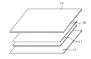
以下本願の発明を図示の実施の形態によって説明する。まず光反射シートについて説明すると、光反射シートは図1および図2に示すように所定の厚さを有するポリエステル発泡シート10から構成される。
【0013】
このような熱可塑性ポリエステル発泡シートとしては、例えばポリエチレンテレフタレートやポリブチレンテレフタレート等の発泡体シートであり、平均気泡径が100μm以下、より好ましくは50μm以下の微細気泡を有し、かつ厚みが200μ以上,より好ましくは500μm以上で、比重が0.7以下のものが用いられる。
【0014】
平均気泡径が100μmより大きいものは、光源からの光を受けたときに光がシートの内部にまで浸透したり、また気泡界面における乱反射の回数も減少することによって、光反射板としての拡散反射率が低下傾向を示すようになる。また平均気泡径は50μm以下であることがより好ましい。しかしながらこの平均気泡径が可視光の波長よりも小さくなると、光がシートを透過して光反射板としての機能を喪失するために、平均気泡径としては少なくとも可視光の波長より大きいことが好ましい。
【0015】
またシート10の厚みが200μmより薄くなると、仮に他の要件を満たしていたとしても、シートの背面に漏洩する光の量が増加するために拡散反射率の低下が起る。しかも形状保持性も劣るようになって取扱い難くなる。よってシートの厚みは200μm以上、より好ましくは500μm以上である。
【0016】
また発泡シート10の比重が0.7を超えるものは、微細気泡の存在割合が小さいものであるために、気泡が存在していない部分における光吸収や透明化に基く光透過等の減少によって、光損失が増大し、その結果シート10の拡散反射率は低下する。しかしながら比重が小さくなりすぎるとシートは気泡の存在割合が多すぎてその強度の低下を招くために、比重は0.05以上であることが好ましい。なおここで言う比重とは水中置換法で測定された値のことを言う。このような熱可塑性ポリエステル発泡シート10としては、例えばMCPET(商品名、古河電工株式会社製)を好適例として挙げることができる。
【0017】
本実施の形態においては熱可塑性ポリエステル発泡シート10として、平均気泡径が10μmで、厚みが1mmで、密度が0.27g/cm3 であって、400〜700nmの光に対する拡散反射率が94〜95%のポリエチレンテレフタレートシートを用いている。なおここで言う拡散反射率とは、硫酸バリウムの微粉末を固めた白色板に対して400〜700nmの波長域において分光光度計で測定したときの値を100としたときの相対値で示すものである。
【0018】
このようなポリエステル発泡シート10の背面側であって光の入射および出射する面とは反対側の面に図1および図2に示すように、カーボングラファイトシート11が接合される。
【0019】
炭素はダイヤモンド、グラファイト(黒鉛)、および無定形炭素の形態で安定に存在する。この内とくにグラファイトは黒色不透明であって六方晶系の結晶構造を有し、電気および熱の導体である。
【0020】
このようなグラファイトは天然に存在する。そしてこのような天然のグラファイトを圧延することによってグラファイトシートが得られる。またアクリロニトリルを用いたアクリル系樹脂フィルム等の有機合成フィルムを無酸素下で焼成すると、シート状のグラファイトが得られる。シート状のグラファイトは柔軟性および圧縮弾性があり、しかも相手材となじみがよいために、ガスケットやパッキンの原料として広く利用されている。ここでは天然に存在する黒鉛を圧延してシート状に構成したグラファイトシート10が用いられる。
【0021】
このように本実施の形態の光反射シートは図1および図2に示すように、ポリエステル発泡シート10の背面側にカーボングラファイトシート11を接合したものである。カーボングラファイトシート11の表面は白色ではないものの、光沢をもった平坦な反射面を構成しており、このためにポリエステル発泡シート10の前面側から入射した光がポリエステル発泡シート10を透過した後にカーボングラファイトシート11の表面で反射され、再びポリエステル発泡シート10の内部を透過してこのポリエステル発泡シート10の表面から前方に出射される。すなわちポリエステル発泡シート10を透過する光の大半を前方に反射することが可能になり、これによって光のロスが少なくなり、光の利用効率が改善される。
【0022】
またカーボングラファイトシート11は熱の良好な導体を構成しており、このためにポリエステル発泡シート10内で生じた熱をカーボングラファイトシート11によって放熱することが可能になる。すなわちカーボングラファイトシート11がこの光反射シートの放熱板を構成することになり、このために光反射シートの過度の温度上昇が防止される。
【0023】
またカーボングラファイトシート11はフレキシブルであるために、ポリエステル発泡シート10の柔軟性を損うことがない。よってカーボングラファイトシート11を接合した光反射シートは、フレキシブルなシートになる。またアルミニウム板を接合した場合よりもカーボングラファイトシート11を接合した場合の方が軽量になり、これによってより軽量な光反射シートが提供される。
【0024】
次に図3によって別の実施の形態を説明する。この実施の形態はポリエステル発泡シート10の表面であって光が入射および出射する表面に凹凸12を形成し、これによって光の出射の方向をランダムにしたものである。このような凹凸12はこのポリエステル発泡シート10の長さ方向あるいは幅方向に形成される筋から構成されてよい。またこのような筋はその断面形状が二等辺三角形の筋であってよく、あるいはまた両側の斜辺の長さおよび角度が異なる異形の三角形の筋であってよい。また断面が円弧状をなす溝によって形成される筋であってよい。
【0025】
また凹凸12はポリエステル発泡シート10の縦方向と横方向とにそれぞれ形成して成る互いに交差する筋から構成されることも可能である。あるいはまたこの発泡シート10の表面に形成された凹部から構成されてよい。あるいはまた不規則な凹凸によって形成することもできる。またポリエステル発泡シート10の表面に多数の切込みを形成したものであってよい。あるいはまた不規則な模様によって凹凸を形成してもよい。あるいは発泡シート10の表面に梨地模様を形成し、これによって発泡シート10の表面に凹凸を形成することもできる。
【0026】
次に別の実施の形態を図4〜図6によって説明する。この実施の形態はポリエテル発泡シート10とカーボングラファイトシート11との間にさらに反射フィルム15を介在させたものである。カーボングラファイトシート11はその表面が光沢を有しているために、このカーボングラファイトシート11の表面それ自身が反射面となるものの、完全な白色でないために、一部の光がカーボングラファイトシート11によって吸収される。これによってポリエステル発泡シート10を透過した光の一部がカーボングラファイトシート11によって吸収されて光損失になる。
【0027】
そこでこのようなカーボングラファイトシート11によって吸収される光によるロスを防止するために、ポリエステル発泡シート10とカーボングラファイトシート11との間に非結晶性の不透明な白色の光沢のある反射フィルム15を介在させ、この反射フィルム15によってポリエステル発泡シート10を透過した光を反射させることができる。なお反射フィルム15としては非結晶性の高分子フィルムに代えて、アルミニウム箔等の金属箔を用いることができる。あるいはまたポリエステル発泡シート10とカーボングラファイトシート11との接合面において、両者の内の一方の表面に形成された蒸着膜等の薄膜から成る反射層によって構成することもできる。
【0028】
このような反射フィルム15あるいは反射コート層の形成によって、ポリエステル発泡シート10を透過した光をより完全に前方に反射することが可能になり、光の透過のロスをより少なくすることが可能になる。なおここでも図6に示すように、ポリエステル発泡シート10の表面であって光が入射および出射する面に凹凸12を形成しておくことが好ましい。
【0029】
次に別の実施の形態を図7によって説明する。この実施の形態はポリエステル発泡シート10とカーボングラファイトシート11とから成る光反射シートにおいて、両者の間に反射フィルム15を介在させ、さらにカーボングラファイトシート11の背面側に包装フィルム16を接合したものである。ここで包装フィルム16は例えば液晶ポリマから構成される。
【0030】
液晶ポリマには、溶液中で液晶性を示すリオトロピック液晶ポリマと、溶融状態で液晶性を示すサーモトロピック液晶ポリマがある。構造的にはパラフェニレンがつながることにより、高い軸比(分子の長さと幅の比、アスペクト比)をもった剛直鎖を形成する主鎖型液晶ポリマと、ビニルポリマ等の主鎖に側鎖として棒状の分子がぶら下がった側鎖型液晶ポリマがある。
【0031】
ポリ(P−フェニレンテレフタルアミド)に代表されるプラスチック用液晶ポリマとしてはXydarとVectraが知られている。これらはガラス充填PEPに匹敵する引張り強度をもち、しかも優れた電気特性を示し、加工が容易である特徴をもっている。また溶融粘度が低く、加工に使われる剪断速度は温度に依存しない。Vectraでは従来の射出成形機が用いられるが、Xydarでは融点が高いので、機械の改良が必要となる。Xydarは高温での性能に優れている。マイクロ波を吸収せず、熱変形温度も高いので、Xydarは電子レンジに使える食器として好適に用いられる。また電気特性がよく、成形収縮が小さいので、電気、電子部品への応用にも適したものである。耐化学薬品性が要求される蒸留塔用のパッキンとして、1種類のVectraで数種類の高価な金属部品を代替できるとされている。本実施の形態においては、ポリプラスチック株式会社製のVectraが上記包装フィルム16として用いられている。
【0032】
なおここで液晶ポリマから成る包装フィルム16はその寸法がカーボングラファイトシート11の周縁部においてはカーボングラファイトシート11よりも一回り大きくなっており、包装フィルム16の周囲の部分が反射フィルム15の周縁部あるいはポリエステル発泡シート10の周縁部と直接接合されるようになっている。これによってカーボングラファイトシート11が完全に包囲されるとともに、包装フィルム16が確実に反射フィルム15またはポリエステル発泡シート10に接合されることになる。このような構造にすると、カーボングラファイトシート11からのカーボン粉末の脱落や離散に伴う飛散が確実に防止されるようになる。
【0033】
次に上述のような光反射シートを用いた面状光源装置について図10および図11により説明する。このような光反射シートは液晶パネル20のバックライトの光反射シートとして用いられる。液晶パネル20の背面側には例えばアクリル樹脂等の透明または半透明の導光板21が配されるとともに、この導光板21の側端面に対向するように光源22が配される。なお光源22の導光板21と対向する面とは反対側の部分に円弧状をなす反射体23が配され、これによって光源22からの光を導光板21内により効果的に導くようにしている。
【0034】
上記導光板21の液晶パネル20とは反対側の面に光反射シートが配される。この光反射シートがポリエステル発泡シート10とカーボングラファイトシート11との接合構造から成り、両者の間に反射フィルム15が配されるようになっている。
【0035】
このような面状光源装置は、背面側に反射フィルム15を備えるポリエステル発泡シート10によって背面側に透過する光を前方に導くことが可能になり、非常に明るい液晶パネルを提供することが可能になる。しかもポリエステル発泡シート10の背面側に接合されているカーボングラファイトシート11が放熱板を構成するために、この放熱板によってポリエステル発泡シート10あるいは導光板21の熱を逃がすことが可能になり、放熱性に優れた液晶パネル20になる。しかもカーボングラファイトシート11それ自体が軽量であるために、面状光源装置の重量をもより軽量化することが可能になる。
【0036】
以上本願発明を図示の実施の形態によって説明したが、本願に含まれる発明は上記実施の形態によって限定されることなく、本願の発明の技術的思想の範囲内で各種の変更が可能である。例えばポリエステル発泡シート10の背面側の反射手段やポリエステル発泡シート10に形成される凹凸12の形状や配置等は、上記実施の形態によって限定されることなく、各種の変形が可能である。またこのような反射シートは必ずしも液晶表示装置の面状光源装置に利用されるだけでなく、その他各種の光学装置に広く利用可能である。
【0037】
【発明の効果】
本願に含まれる主要な発明は、平均気泡径が100μm以下の微細気泡を有し、厚みが200μm以上で比重が0.7以下の熱可塑性ポリエステル発泡シートの光が入射および出射する面とは反対側の面にカーボングラファイトシートを接合するとともに、発泡シートとカーボングラファイトシートとの接合面に反射層を設け、ポリエステル発泡シートを透過した光が該ポリエステル発泡シートの表面から出射するように反射させるようにしたものである。
【0038】
従ってこのような光反射シートによれば、接合されたカーボングラファイトシートによってこの光反射シートに対して優れた放熱性を付与することが可能になるとともに、この発泡シートを透過した光をカーボングラファイトシートの表面で反射して前方に導くことが可能になり、これによって光の利用効率が改善される。
【0039】
面状光源装置に関する主要な発明は、透明または半透明の導光板と、導光板の背面に配され、光を導光板に導く光反射シートと、導光板の側面に設けられる光源と、を具備し、光反射シートが平均気泡径が100μm以下の微細気泡を有し、厚みが200μm以上で比重が0.7以下の熱可塑性ポリエステル発泡シートの光が入射および出射する面とは反対側の面にカーボングラファイトシートを接合するとともに、ポリエステル発泡シートとカーボングラファイトシートとの接合面に反射層を設けるようにしたシートから構成されるようにしたものである。
【0040】
従ってこのような面状光源装置によれば、カーボングラファイトシートによってこの面状光源装置で発生する熱を逃がすことが可能になる。またカーボングラファイトシートの表面で発泡シートを透過する光を導光板側に反射することが可能になり、これによって光の利用効率が改善され、より明るい面状光源装置が提供される。
【図面の簡単な説明】
【図1】光反射シートの分解斜視図である。
【図2】同要部拡大断面図である。
【図3】別の実施の形態の光反射シートの縦断面図である。
【図4】別の実施の形態の光反射シートの分解斜視図である。
【図5】同光反射シートの縦断面図である。
【図6】別の実施の形態の光反射シートの縦断面図である。
【図7】さらに別の実施の形態の光反射シートの分解斜視図である。
【図8】同要部縦断面図である。
【図9】全体の構造を示す縦断面図である。
【図10】光反射シートを用いた面状光源装置の要部分解斜視図である。
【図11】同要部縦断面図である。
【符号の説明】
10 ポリエステル発泡シート
11 カーボングラファイトシート
12 凹凸
15 反射フィルム
16 包装フィルム
20 液晶パネル
21 導光板
22 光源
23 反射体[0001]
BACKGROUND OF THE INVENTION
BACKGROUND OF THE INVENTION 1. Field of the Invention The present invention relates to a light reflecting sheet and a planar light source device using the light reflecting sheet, and more particularly to a light reflecting sheet that effectively illuminates a predetermined position using light from the light source and such a light reflecting sheet. The present invention relates to a planar light source device using the above.
[0002]
[Prior art]
In general, a light source for illumination guides light to the front side and reflects light emitted to the back side toward the front side by a reflecting plate. The reflecting plate for reflecting the light on the back side is made of an iron plate or an aluminum plate, and a white coated steel plate or a white color aluminum plate or the like whose surface is baked with melamine resin is used.
[0003]
When such a metal white paint plate is used as a reflector of a fluorescent lamp, diffuse reflection of light occurs, and the reflected light becomes a reflected light that is relatively soft to the eyes, but its reflectance is about 85%. In addition, the brightness of the light source is lost by about 15% during reflection. Moreover, the reflectance is an average value as a whole. For example, the reflectance of blue visible light having a wavelength of 400 nm is about 90%, but the reflectance of red visible light having a wavelength of 700 nm is about 90%. 80%. That is, when the above-mentioned white painted plate is used, the light amount of the light source as a whole is lost by 15% at the time of reflection, and in the case of a red light component, it is lost by about 20%, and the reflected light is bluish as a whole. Get dark.
[0004]
In view of such problems, for example, Japanese Patent Application Laid-Open No. 2001-184914 discloses a polyester having closed cells with an average cell diameter of 50 μm or less, a thickness of 200 μm or more, and a density of 0.7 g / cm 3 or more. Resin foam sheets have been proposed. When light is reflected by such a sheet, visible light having a wavelength of 400 to 700 nm can be reflected with a reflectance of 90% or more.
[0005]
[Problems to be solved by the invention]
However, this type of light reflecting sheet easily transmits light in a short wavelength region, and there is a problem that the transmitted light is not effectively used. Further, when the light reflecting sheet itself generates heat, the temperature rises. In view of such a problem, for example, an aluminum plate is bonded to a surface on the back side of the light reflecting sheet and opposite to a surface on which light enters and exits.
[0006]
However, when an aluminum plate is joined to the back side of the light reflecting sheet, there is a problem that the weight of the light reflecting sheet increases, and weight reduction is hindered. Further, since the aluminum plate itself is not flexible, the flexible property of the light reflecting sheet is impaired.
[0007]
The present invention has been made in view of such problems, and is a light that guides light transmitted through the light reflecting sheet forward, and prevents the light reflecting sheet from excessively rising in temperature. An object is to provide a planar light source device using a reflection sheet and a light reflection sheet.
[0008]
[Means for Solving the Problems]
The main invention of this application is:
Surface on which light enters and exits a thermoplastic polyester foam sheet having fine bubbles having an average cell diameter of 100 μm or less, more preferably 50 μm or less, a thickness of 200 μm or more, more preferably 500 μm or more and a specific gravity of 0.7 or less. A carbon graphite sheet is bonded to the surface opposite to the surface, and a reflection layer is provided on the bonding surface between the polyester foam sheet and the carbon graphite sheet, and light transmitted through the polyester foam sheet is transmitted from the surface of the polyester foam sheet. The present invention relates to a light reflecting sheet characterized by being reflected so as to be emitted .
[0009]
Here, the reflective layer is interposed between the foamed sheet and the carbon graphite sheet, or the foamed sheet and the carbon graphite sheet at a joint surface between the foamed sheet and the carbon graphite sheet. A reflective coating layer formed on one side is preferred.
[0010]
The main invention related to the planar light source device is a transparent or translucent light guide plate,
A light reflecting sheet disposed on the back surface of the light guide plate and guiding light to the light guide plate;
A light source provided on a side surface of the light guide plate;
And the light reflecting sheet has fine bubbles with an average cell diameter of 100 μm or less, more preferably 50 μm or less, a thickness of 200 μm or more, more preferably 500 μm or more and a specific gravity of 0.7 or less. configured with joining carbon graphite sheet on the opposite side from the sheet so as to provide a reflective layer on the junction surface between the polyester foam sheet and the carbon graphite sheet to the surface on which the light sheet is incident and exit The present invention relates to a planar light source device.
[0011]
Here, it is preferable that such a planar light source device is used as a backlight of a liquid crystal panel.
[0012]
DETAILED DESCRIPTION OF THE INVENTION
The invention of the present application will be described below with reference to the illustrated embodiments. First, the light reflecting sheet will be described. The light reflecting sheet includes a
[0013]
As such a thermoplastic polyester foam sheet, for example, a foam sheet such as polyethylene terephthalate or polybutylene terephthalate has an average cell diameter of 100 μm or less, more preferably 50 μm or less, and a thickness of 200 μm or more. , More preferably 500 μm or more and specific gravity of 0.7 or less.
[0014]
When the average bubble diameter is larger than 100 μm, when light from the light source is received, the light penetrates into the inside of the sheet, and the number of diffuse reflections at the bubble interface is reduced, so that diffuse reflection as a light reflecting plate is achieved. The rate shows a downward trend. The average cell diameter is more preferably 50 μm or less. However, when the average bubble diameter is smaller than the wavelength of visible light, the light passes through the sheet and loses its function as a light reflector. Therefore, the average bubble diameter is preferably at least larger than the wavelength of visible light.
[0015]
Further, when the thickness of the
[0016]
In addition, the
[0017]
In the present embodiment, the thermoplastic
[0018]
As shown in FIGS. 1 and 2, a
[0019]
Carbon exists stably in the form of diamond, graphite (graphite), and amorphous carbon. In particular, graphite is black opaque, has a hexagonal crystal structure, and is an electrical and thermal conductor.
[0020]
Such graphite exists in nature. And a graphite sheet is obtained by rolling such natural graphite. Further, when an organic synthetic film such as an acrylic resin film using acrylonitrile is baked in the absence of oxygen, a sheet-like graphite is obtained. Sheet-like graphite is widely used as a raw material for gaskets and packings because it has flexibility and compression elasticity and is compatible with other materials. Here, a
[0021]
As described above, the light reflecting sheet of the present embodiment is obtained by bonding the
[0022]
In addition, the
[0023]
Moreover, since the
[0024]
Next, another embodiment will be described with reference to FIG. In this embodiment,
[0025]
Moreover, the unevenness |
[0026]
Next, another embodiment will be described with reference to FIGS. In this embodiment, a
[0027]
Therefore, in order to prevent such loss due to light absorbed by the
[0028]
By forming such a
[0029]
Next, another embodiment will be described with reference to FIG. This embodiment is a light reflecting sheet composed of a
[0030]
The liquid crystal polymer includes a lyotropic liquid crystal polymer exhibiting liquid crystallinity in a solution and a thermotropic liquid crystal polymer exhibiting liquid crystallinity in a molten state. The main chain type liquid crystal polymer that forms a rigid linear chain with a high axial ratio (ratio of molecular length to width, aspect ratio) and a side chain on the main chain of vinyl polymer, etc. There is a side chain type liquid crystal polymer in which rod-like molecules are suspended.
[0031]
Xydar and Vectra are known as liquid crystal polymers for plastics represented by poly (P-phenylene terephthalamide). These have a tensile strength comparable to that of glass-filled PEP, have excellent electrical properties, and are easily processed. Also, the melt viscosity is low and the shear rate used for processing is independent of temperature. In Vectra, a conventional injection molding machine is used, but in Xydar, the melting point is high, so the machine needs to be improved. Xydar has excellent performance at high temperatures. Since it does not absorb microwaves and has a high heat distortion temperature, Xydar is preferably used as a tableware that can be used in a microwave oven. Also, it has good electrical characteristics and small molding shrinkage, so it is suitable for application to electrical and electronic parts. It is said that several types of expensive metal parts can be replaced with one type of Vectra as packing for a distillation column that requires chemical resistance. In the present embodiment, Vectra manufactured by Polyplastics Co., Ltd. is used as the
[0032]
Here, the size of the
[0033]
Next, a planar light source device using the light reflecting sheet as described above will be described with reference to FIGS. Such a light reflecting sheet is used as a light reflecting sheet of a backlight of the
[0034]
A light reflecting sheet is disposed on the surface of the
[0035]
Such a planar light source device can guide light transmitted to the back side forward by the
[0036]
Although the present invention has been described above with reference to the illustrated embodiments, the invention included in the present application is not limited to the above-described embodiments, and various modifications can be made within the scope of the technical idea of the present invention. For example, the reflection means on the back side of the
[0037]
【The invention's effect】
The main invention included in the present application is the opposite of the surface on which light enters and exits the thermoplastic polyester foam sheet having fine bubbles having an average cell diameter of 100 μm or less, a thickness of 200 μm or more and a specific gravity of 0.7 or less. A carbon graphite sheet is bonded to the side surface, and a reflection layer is provided on the bonding surface between the foam sheet and the carbon graphite sheet so that the light transmitted through the polyester foam sheet is reflected so as to be emitted from the surface of the polyester foam sheet. It is a thing.
[0038]
Therefore, according to such a light reflecting sheet, it becomes possible to impart excellent heat dissipation to the light reflecting sheet by the bonded carbon graphite sheet, and the light transmitted through the foamed sheet is transmitted to the carbon graphite sheet. Can be reflected and guided forward, thereby improving the light utilization efficiency.
[0039]
A main invention relating to a planar light source device includes a transparent or translucent light guide plate, a light reflecting sheet disposed on the back surface of the light guide plate to guide light to the light guide plate, and a light source provided on a side surface of the light guide plate. The light-reflecting sheet has fine bubbles with an average cell diameter of 100 μm or less, and has a thickness of 200 μm or more and a specific gravity of 0.7 or less. to thereby bond the carbon graphite sheet, in which so as to be composed of the sheet to provide a reflective layer at the interface between the polyester foam sheet and the carbon graphite sheet.
[0040]
Therefore, according to such a planar light source device, heat generated in the planar light source device can be released by the carbon graphite sheet. In addition, the light transmitted through the foam sheet on the surface of the carbon graphite sheet can be reflected toward the light guide plate, thereby improving the light utilization efficiency and providing a brighter surface light source device.
[Brief description of the drawings]
FIG. 1 is an exploded perspective view of a light reflecting sheet.
FIG. 2 is an enlarged cross-sectional view of the main part.
FIG. 3 is a longitudinal sectional view of a light reflecting sheet according to another embodiment.
FIG. 4 is an exploded perspective view of a light reflecting sheet according to another embodiment.
FIG. 5 is a longitudinal sectional view of the light reflecting sheet.
FIG. 6 is a longitudinal sectional view of a light reflecting sheet according to another embodiment.
FIG. 7 is an exploded perspective view of a light reflecting sheet according to still another embodiment.
FIG. 8 is a longitudinal sectional view of the main part.
FIG. 9 is a longitudinal sectional view showing the entire structure.
FIG. 10 is an exploded perspective view of a main part of a planar light source device using a light reflecting sheet.
FIG. 11 is a longitudinal sectional view of the relevant part.
[Explanation of symbols]
DESCRIPTION OF
Claims (5)
前記導光板の背面に配され、光を導光板に導く光反射シートと、
前記導光板の側面に設けられる光源と、
を具備し、前記光反射シートが平均気泡径が100μm以下の微細気泡を有し、厚みが200μm以上で比重が0.7以下の熱可塑性ポリエステル発泡シートの光が入射および出射する面とは反対側の面にカーボングラファイトシートを接合するとともに、前記ポリエステル発泡シートと前記カーボングラファイトシートとの接合面に反射層を設けるようにしたシートから構成されることを特徴とする面状光源装置。A transparent or translucent light guide plate;
A light reflecting sheet disposed on the back surface of the light guide plate and guiding light to the light guide plate;
A light source provided on a side surface of the light guide plate;
And the light-reflecting sheet has fine bubbles with an average cell diameter of 100 μm or less, opposite to the surface on which light enters and exits the thermoplastic polyester foam sheet having a thickness of 200 μm or more and a specific gravity of 0.7 or less. with bonded carbon graphite sheet to the surface on the side, a surface light source device, characterized in that it consists of sheets to provide a reflective layer on the junction surface between the polyester foam sheet and the carbon graphite sheet.
Priority Applications (1)
| Application Number | Priority Date | Filing Date | Title |
|---|---|---|---|
| JP2002261258A JP4240965B2 (en) | 2002-09-06 | 2002-09-06 | Light reflection sheet and planar light source device using light reflection sheet |
Applications Claiming Priority (1)
| Application Number | Priority Date | Filing Date | Title |
|---|---|---|---|
| JP2002261258A JP4240965B2 (en) | 2002-09-06 | 2002-09-06 | Light reflection sheet and planar light source device using light reflection sheet |
Publications (2)
| Publication Number | Publication Date |
|---|---|
| JP2004101693A JP2004101693A (en) | 2004-04-02 |
| JP4240965B2 true JP4240965B2 (en) | 2009-03-18 |
Family
ID=32261685
Family Applications (1)
| Application Number | Title | Priority Date | Filing Date |
|---|---|---|---|
| JP2002261258A Expired - Fee Related JP4240965B2 (en) | 2002-09-06 | 2002-09-06 | Light reflection sheet and planar light source device using light reflection sheet |
Country Status (1)
| Country | Link |
|---|---|
| JP (1) | JP4240965B2 (en) |
Cited By (1)
| Publication number | Priority date | Publication date | Assignee | Title |
|---|---|---|---|---|
| CN103547121A (en) * | 2012-07-09 | 2014-01-29 | 华宏新技股份有限公司 | Radiation compound and application thereof |
Families Citing this family (22)
| Publication number | Priority date | Publication date | Assignee | Title |
|---|---|---|---|---|
| US8480282B2 (en) | 2005-08-30 | 2013-07-09 | Lg Display Co., Ltd. | Reflective plate and method for manufacturing the same and backlight unit for liquid crystal display device using the same |
| CN100456102C (en) * | 2005-08-30 | 2009-01-28 | 乐金显示有限公司 | Reflective plate and method for manufacturing the same and backlight unit and liquid crystal display device having the same |
| EP1777579B1 (en) * | 2005-10-24 | 2008-07-09 | LG Electronics Inc. | Backlight unit having heat dissipating layer, display device having heat dissipating layer, and method for manufacturing heat dissipating layer |
| KR101248161B1 (en) * | 2006-02-08 | 2013-03-27 | 엘지전자 주식회사 | Thermal spreading layer, backlight unit and display apparatus including the same |
| KR100771110B1 (en) * | 2006-02-21 | 2007-10-29 | 서울반도체 주식회사 | Backlight Unit and Liquid Crystal Display having the same |
| KR100820676B1 (en) * | 2006-06-15 | 2008-04-10 | 엘지전자 주식회사 | Backlight unit with thermal spreading layer and display apparatus including the same |
| JP4938466B2 (en) * | 2007-01-12 | 2012-05-23 | 帝人株式会社 | Electronic mounting board, light reflective heat conductive coverlay film |
| JP4175433B2 (en) * | 2007-02-09 | 2008-11-05 | ソニー株式会社 | Optical element package, backlight, and liquid crystal display device |
| US20090303413A1 (en) * | 2007-02-13 | 2009-12-10 | Sony Corporation | Optical sheet packaged body, optical sheet unit, lighting device, and display unit |
| JP4148299B1 (en) * | 2007-02-13 | 2008-09-10 | ソニー株式会社 | Optical package and manufacturing method thereof, lighting device, and display device |
| KR101392734B1 (en) | 2007-12-21 | 2014-05-09 | 삼성디스플레이 주식회사 | Backlight assembly, display device having the backlight assembly and method of manufacturing the same |
| JP2010044952A (en) * | 2008-08-12 | 2010-02-25 | Sony Corp | Optical packing body, lighting device, and display device |
| KR20120021107A (en) * | 2010-08-31 | 2012-03-08 | 엘지디스플레이 주식회사 | Reflecting sheet and method for fabricating the same |
| WO2014208368A1 (en) * | 2013-06-27 | 2014-12-31 | 堺ディスプレイプロダクト株式会社 | Light source device and display device |
| WO2015045979A1 (en) * | 2013-09-27 | 2015-04-02 | 東レ株式会社 | White polyester film |
| CN203748176U (en) * | 2014-01-20 | 2014-07-30 | 苏州贺尔新电子有限公司 | Novel heat dissipation reflecting sheet |
| JP6498384B2 (en) * | 2014-03-22 | 2019-04-10 | 株式会社大木工藝 | Building material sheet |
| WO2017019450A2 (en) | 2015-07-24 | 2017-02-02 | 3M Innovative Properties Company | Reflective stack with heat spreading layer |
| CN105676527A (en) * | 2016-02-18 | 2016-06-15 | 广东欧珀移动通信有限公司 | Back light module and liquid crystal display device |
| CN105842920A (en) * | 2016-04-29 | 2016-08-10 | 佛山市南海区联合广东新光源产业创新中心 | LED backlight module |
| KR101924567B1 (en) | 2016-12-16 | 2018-12-03 | 에스케이씨하이테크앤마케팅(주) | Heat-dissipative shielding sheet and preparation method thereof |
| TWI786715B (en) | 2020-07-21 | 2022-12-11 | 日商日亞化學工業股份有限公司 | Light-emitting module and planar light source |
-
2002
- 2002-09-06 JP JP2002261258A patent/JP4240965B2/en not_active Expired - Fee Related
Cited By (1)
| Publication number | Priority date | Publication date | Assignee | Title |
|---|---|---|---|---|
| CN103547121A (en) * | 2012-07-09 | 2014-01-29 | 华宏新技股份有限公司 | Radiation compound and application thereof |
Also Published As
| Publication number | Publication date |
|---|---|
| JP2004101693A (en) | 2004-04-02 |
Similar Documents
| Publication | Publication Date | Title |
|---|---|---|
| JP4240965B2 (en) | Light reflection sheet and planar light source device using light reflection sheet | |
| CN1170191C (en) | Background light and LCD | |
| JP5089960B2 (en) | Surface light source device, backlight unit including the same, and liquid crystal display device including the backlight unit | |
| WO2003044572A1 (en) | Light diffusive sheet | |
| EP1892563B1 (en) | Surface light source device, backlight unit and liquid crystal display having the same | |
| TW200537201A (en) | Optical material, optical element, illuminator and display device | |
| WO2007049515A1 (en) | Light transmitting resin board | |
| WO2004076917A1 (en) | Area light source | |
| JP2004513483A (en) | Bright and contrast enhanced direct-view luminescent display | |
| JP2009087762A (en) | Light guide plate, light guide plate unit, and planar lighting system | |
| KR100808328B1 (en) | Light Diffusing Plate | |
| JP5428313B2 (en) | Light uniform element and backlight unit and display device using the same | |
| JP2007086098A (en) | Optical sheet and liquid crystal display device | |
| JP2003315560A (en) | Light transmission body, surface light source device using the same, and liquid crystal display device | |
| JP2014235991A (en) | Luminaire | |
| JP2000056136A (en) | Light fiber and its manufacture | |
| JP2011033643A (en) | Optical path changing sheet, backlight unit and display device | |
| JP2009123397A (en) | Illumination device, and image display device using it | |
| JP5391798B2 (en) | Backlight unit and display device | |
| JP2004029648A (en) | Light diffusing sheet | |
| JPH1138232A (en) | Flat light-emitting panel | |
| JPH08146230A (en) | Surface light emitting device | |
| JP5593653B2 (en) | Light guide plate, backlight unit and display device | |
| JP4680847B2 (en) | Surface lighting device | |
| JP2007298698A (en) | Light diffusing plate and planar irradiation apparatus |
Legal Events
| Date | Code | Title | Description |
|---|---|---|---|
| A621 | Written request for application examination |
Free format text: JAPANESE INTERMEDIATE CODE: A621 Effective date: 20050729 |
|
| A977 | Report on retrieval |
Free format text: JAPANESE INTERMEDIATE CODE: A971007 Effective date: 20080417 |
|
| A131 | Notification of reasons for refusal |
Free format text: JAPANESE INTERMEDIATE CODE: A131 Effective date: 20080604 |
|
| A521 | Written amendment |
Free format text: JAPANESE INTERMEDIATE CODE: A523 Effective date: 20080804 |
|
| TRDD | Decision of grant or rejection written | ||
| A01 | Written decision to grant a patent or to grant a registration (utility model) |
Free format text: JAPANESE INTERMEDIATE CODE: A01 Effective date: 20081210 |
|
| A01 | Written decision to grant a patent or to grant a registration (utility model) |
Free format text: JAPANESE INTERMEDIATE CODE: A01 |
|
| A61 | First payment of annual fees (during grant procedure) |
Free format text: JAPANESE INTERMEDIATE CODE: A61 Effective date: 20081222 |
|
| FPAY | Renewal fee payment (event date is renewal date of database) |
Free format text: PAYMENT UNTIL: 20120109 Year of fee payment: 3 |
|
| R150 | Certificate of patent or registration of utility model |
Free format text: JAPANESE INTERMEDIATE CODE: R150 |
|
| LAPS | Cancellation because of no payment of annual fees |