JP4240441B2 - Friction welding method and apparatus - Google Patents
Friction welding method and apparatus Download PDFInfo
- Publication number
- JP4240441B2 JP4240441B2 JP2001255812A JP2001255812A JP4240441B2 JP 4240441 B2 JP4240441 B2 JP 4240441B2 JP 2001255812 A JP2001255812 A JP 2001255812A JP 2001255812 A JP2001255812 A JP 2001255812A JP 4240441 B2 JP4240441 B2 JP 4240441B2
- Authority
- JP
- Japan
- Prior art keywords
- friction
- base material
- friction welding
- time
- relative motion
- Prior art date
- Legal status (The legal status is an assumption and is not a legal conclusion. Google has not performed a legal analysis and makes no representation as to the accuracy of the status listed.)
- Expired - Fee Related
Links
Images


Landscapes
- Pressure Welding/Diffusion-Bonding (AREA)
Description
【0001】
【発明の属する技術分野】
本発明は、摩擦圧接方法及び装置に関し、詳しくは、溶接入熱、バリ、よりしろの発生が極めて少量である摩擦圧接方法及び装置に関する。
【0002】
【従来の技術】
摩擦圧接の基本原理は、摩擦推力のもとで被接合材の接合面同士を回転接触することによって、摩擦熱を発生させ、接合部の温度を上昇させる摩擦過程と、摩擦推力と同等、あるいはそれ以上の推力を負荷することにより、接合部をより密着させるアプセット過程の、二つの過程から構成される。
【0003】
摩擦圧接には、いくつかの手法があるが、特に、母材の一方を固定し、他方を回転させ、両母材を接触させて軸方向に摩擦推力を与え、接合可能温度に達したらブレーキをかけ、強制的に減速させつつ、アプセット推力を加えて接合を完了するブレーキ法と、回転軸に取り付けられたフライホィールに蓄積された回転エネルギーが、母材同士の接触により生じた熱エネルギーに変換されることで、回転を停止させ接合を完了する、フライホィール式がよく知られている。
【0004】
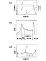
摩擦圧接において、バリまたはよりしろの発生は、必ず起こる現象である。例えば軟鋼材を摩擦圧接法によって接合する場合に、その接合過程における摩擦トルクと、接合部材の相対回転速度、加圧力、そしてよりしろの関係を表したものを図6(a)及び(b)に示す。摩擦圧接溶接中の摩擦トルクは図中に示すように4つの領域(第1から第4位相)に区分される。また、接合部材がアルミニウム合金である場合には、図6(c)に示すように、軟鋼材に比較して位相の変化は顕著ではないが、摩擦トルクの初期最大値Aと時間領域Bにおける定常状態を確認できる。
【0005】
同図のように、両母材の接合端面が加圧力p、相対回転速度vで接触後、摩擦トルクが上昇し、ピークに達するまでは、よりしろδは殆ど形成されない。その領域を第1位相と呼ぶ。さらに摩擦を続けると、トルクは初期最大値(初期トルクピーク)から減少し定常状態に達する。初期トルクピークから定常状態に入るまでの領域を第2位相と呼ぶ。つまり、両母材の接合面の摩擦トルクが初期最大値から定常状態に移るまでの時間領域に対応する。定常状態に入った頃からよりしろが急激に増加し初め、さらに摩擦を続けると摩擦トルクは略一定値を示し、よりしろは時間に比例して増加する。その領域を第3位相と呼ぶ。
【0006】
最後に回転側にブレーキをかけ、回転速度を減少すると同時に加圧力を増加し、回転速度が零になるまで加圧力を加え続ける。この過程がアプセット過程と呼ばれ、このときバリはさらに大きくなる。その領域を第4位相と呼ぶ。
【0007】
摩擦圧接の際の摩擦トルクをモニターすると、前述のように第1位相から第4位相に区分けされる。摩擦圧接に関するJIS規格(JIS Z 3607)では、継手の強度を確保するために、十分に摩擦入熱を大きくし、よりしろを8mm以上取ることを規定している。すなわち、第3位相まで摩擦圧接させた後、ブレーキをかけて溶接を終了する。
【0008】
この際、回転軸にブレーキをかけてから、接合する両部材の相対回転速度が零になるまで、ある時間が経過するため、この間に摩擦面の温度は急激に低下する。そのため、相対回転速度が零になったときに、接合可能な温度を維持するため、摩擦過程中に摩擦面あるいはその近傍に多くの熱量を入れておく必要がある。その結果、その接合面は余分な熱量として多くのバリを排出しての接合となる。
【0009】
上記のように摩擦過程中に余分な入熱を入れたり、長い摩擦時間を要したりすると、接合母材において、接合部分とは無関係な部分にも熱の影響を与えてしまうことになる。それにより母材は、熱の影響による母材軟化や熱影響部の脆化など、その機械的性質を劣化させられてしまう恐れがある。特に、熱処理で調質された材料の場合、上記の母材軟化を避ける必要がある。
【0010】
また、バリの排出が大きいと、そのバリを除去するための加工に多大な時間を要す。あるいはその分、母材を無駄にしていると言える。なお、一説によると、バリは接合端面の不純物を排出する目的で、ある程度必要であるとも言われているが、拡散接合でも見られるように、接合に際しては不純物の排出としての大きなバリは必ずしも必要でない。
【0011】
特公昭58−28038は、摩擦過程中の接合端面を外側から冷却することで、バリの少ない接合部を得る方法を示している。しかしこの方法では、ブレーキ式摩擦圧接装置の他、接合母材の摩擦面を四方から冷却する冷却用装置が必要である。
【0012】
バリ、よりしろをできるだけ減らすために、接合面の摩擦トルクをモニターしてブレーキタイミングを決定する方法が、特開平11−47958等に示されている。この方法では、減速するタイミングは摩擦トルクが定常状態を示す領域で設定されているため、上述の図5から分かるように、その領域はバリ、よりしろが時間に比例して増加していくところであるため、バリはある程度生じてしまう。
【0013】
また、ブレーキ法やフライホィール法では、両母材の相対回転運動が完全に停止するまでの間、ある時間が必要である。その間、両母材の接合部は、接合とねじり破壊を繰り返しながら冷却されることになる。そうするとその接合部は良好な接合とならないため、上述のように、摩擦過程中に摩擦面あるいはその近傍に多くの熱量を入れておく必要があった。
【0014】
【発明が解決しようとする課題】
本発明は摩擦圧接における、バリあるいはよりしろの大幅な縮小により、母材のロスを減少させ、また、余分な入熱の必要のない工程であるため、母材への熱影響による母材軟化や熱影響部の脆化など、その機械的性質の劣化を招くことのない、低入熱の摩擦圧接方法及びそれを行う摩擦圧接装置を提供することを目的とする。
【0015】
【課題を解決するための手段】
上記目的を達成するため、本発明者は、上記の低入熱摩擦圧接溶接法に関して、鋭意研究した結果、母材の接合面における特定の位相領域で、母材の相対回転速度を瞬間的に零にすることで、摩擦圧接が完了できることを見いだし、本発明を完成するに至ったのである。
【0016】
すなわち本発明は、2本の被接合母材を突合わせて、これらの軸方向に圧力を加えながら相対運動させることにより、被接合母材の接合面にこれらが接合する温度の摩擦熱を発生させる摩擦圧接方法において、2本の被接合母材間の相対運動の終了は、これら母材の接合面の摩擦トルクが初期最大値から定常状態に移るまでの時間領域で行なわれることを特徴とする。特には、前記相対運動が、前記2本の被接合母材の接合面の摩擦トルクが最大値から定常状態に移るまでの時間領域で終了するように、相対運動を開始してから終了するまでの摩擦時間を定めるステップと、前記相対運動を開始するステップと、前記相対運動を前記定めた摩擦時間行うステップと、前記定めた摩擦時間経過した時に前記相対運動を終了するステップと、を含む、ことを特徴とする。
【0017】
さらに、本発明は、相対運動の終了後に、前記被接合母材の接合面に対し、前記相対運動中に加える圧力と同等もしくはそれ以上の圧力をかけることを特徴とする。
【0018】
さらに、相対運動は、一の母材を回転運動させ他の母材を固定して行い、時間領域の終点を、接合面の摩擦トルクが初期最大値から所定量減少する時点として定め、この時点で、他の母材の固定を解除することにより、他の母材を一の母材と共に同調回転させることにある。
【0020】
本発明が取り扱う摩擦圧接方法は、ブレーキ法による方法であれば、いかなる場合にも応用が可能である。例えば片側を回転軸、もう片側を固定軸とする方法や、溶接する部材の間に中間材を介して接合する方法等に応用できる。
【0021】
上記のような条件で行われる摩擦圧接方法は、排出されるバリ、あるいはよりしろがわずかであり、継手の強度も母材と変わらない、摩擦圧接溶接となる。
【0022】
【発明の実施の形態】
次に、本発明に係わる摩擦圧接方法及び装置について、その実施の形態を説明する。後述の実施例で具体的な構成を明らかにするとして、先ず概要を以下に述べる。
【0023】
母材の接合面の摩擦トルクを測定するには通常のトルク計を用いる。摩擦圧接装置の主軸と連結した軸にトルク検出用のアームを設け、そのアームにかかる荷重をロードセルが受け止め、検出する。
【0024】
ブレーキ式の摩擦圧接方法において、接合する二つの母材の相対回転速度を瞬時に略零にするには、以下に述べるような本発明に係る摩擦圧接装置を使用すれば可能である。
【0025】
当該摩擦圧接装置は、構造的には、一般的なブレーキ法で使用される装置に、トルク測定装置が取り付けられる。母材を締結する固定側チャックは、油圧シリンダーに連結・固定された固定軸に、電磁クラッチを介して自在に連結し又は切断され、電磁クラッチが切断されると自由に回転できる。また、固定側チャックは、スラストベアリングを介して油圧シリンダーに連結しているので、電磁クラッチが切断されても軸(スラスト)方向の力を伝達できる。このため、電磁クラッチの連結・遮断に係わり無く、固定側チャックに締結される母材には、油圧シリンダーによって加圧推力が負荷される。このような摩擦圧接装置では、接合する2つの母材間の相対回転速度を、以下のように瞬時に零にできる。
【0026】
その場合の摩擦トルクと、被接合母材の相対回転速度、加圧力、そしてよりしろの関係を図1に示す。図1(a)のように、相対回転速度vは時間幅を持たずに、瞬時に零となっている。これは、摩擦トルクが第2位相の時に、一方の母材を締結して回転駆動する回転側チャックを図外の摩擦ブレーキ等の制動手段を作動させて急制動し、同時に、他方の母材を締結した固定側チャックを、電磁クラッチを切断することにより回転自在な状態にする。この時、回転側チャックは、その慣性により僅かながら回転を維持しようとし固定側チャックは静止を維持しようとするので、回転側チャックと固定側チャックに各々締結された2つの母材の間で、慣性力に起因する捩れ力が発生するが、既に相互に接合しつつある2つの母材は、捩じり破断するに至らず、前記制動を開始して完全に停止するまでの間、相互に同調回転する。
【0027】
したがって、この極めて短い時間に、2つの母材がある程度慣性力によって回転しても、これらの相対回転速度は零である。このようにして、摩擦トルクが略第2位相の時に相対回転速度を瞬時に零にできるので、摩擦時間を大幅に短縮でき、また、よりしろδが増加する前に接合を完了できる。なお、相対回転速度が零になった後の加圧推力は、摩擦圧接中と同等もしくはそれ以上が適当である。相対回転速度を零にした後、摩擦圧接中と同等の圧力をかける例を図2(a)に示し、相対回転速度を零にした後、摩擦圧接中よりも大きな圧力をかける例を図2(b)に示す。
【0028】
上記の接合工程における接合部材の変化を模式的に表したものが図3である。図3(a)はこれから摩擦圧接される接合母材、(b)は摩擦圧接中の接合母材、(c)は摩擦圧接が完了した接合母材を表す。図3(c)の状態で、2本の試験片の総全長は、略よりしろδの分だけ収縮することになる。このようにして得られる継手(溶接された2つの母材)の接合部のバリ又はよりしろは、従来の方法で行なう場合よりも著しく減少する。
【0029】
ただし、その第2位相での摩擦圧接の終了が、従来のブレーキ法のような、完全停止するまでにある時間を要すると、十分に入熱されていないため、接合部の強制的なねじり破壊が繰り返され、その接合は不良となる。従って、低入熱で完全な摩擦圧接溶接の継手を得るためには、上述のように、第2位相で瞬間的に接合母材の相対回転速度を零にしなければならない。
【0030】
寸法の大きな素材の接合、または異種材料間の接合等の場合、材料の接合面の間に中間材を介在して上記の摩擦圧接溶接を行うが、この場合、その中間材を回転させるようにする。また、上述のような電磁クラッチに換えて、固定側に電磁チャックを適用し、この電磁チャックを、回転摩擦運動を開始してから、摩擦トルクが定常状態に移るまでの時間領域内で固定し、この時点(定常状態)で、制動手段が回転側チャックを制動すると共に電磁チャックを解放するように構成しても良い。
【0031】
なお、本発明の方法において、制動手段は必須ではない。2本の被接合母材が上述の捩じれ破断を起こす可能性がなければ、固定側チャックを積極的に制動することなく、回転側チャックの固定を解除して2本の被接合母材を同調回転させてもよい。また、本発明で表す接合母材間の相対回転速度とは、母材の一方の回転速度と、もう一方の母材の回転速度の差を意味するものである。
【0032】
【実施例】
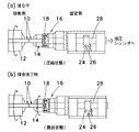
本発明で使用した摩擦圧接装置は、汎用旋盤を改造して製作したブレーキ式摩擦圧接装置であり、その概略図を図4に示した。固定側チャック14には、摩擦トルク測定用のロッド28が主軸と連結されている。そのロッド28の中心部にアーム24が固定され、摩擦推力負荷時のモーメントを受け止めるロードセル26によって、アーム24にかかる荷重を検出することにより、摩擦トルクを測定する構造となっている。
【0033】
固定側チャック14がある時点で瞬間的に解放され、回転側チャック12と同様に回転させる方法として、電磁クラッチ(神鋼電機株式会社製TZ-25型)を使用した。その原理は、電磁クラッチ16のコイルに電流が流れることにより、固定側チャック14と接続されているアーマチュアとローターが噛み合っており、コイルに供給されている電流がストップすると、圧縮スプリングによって噛み合いが外れることにより回転する構造となっている。
【0034】
接合母材として、軟鋼材(JIS G4051 S15CK)を、図5に示すように、接合面1を細径部の先端に形成し拡径部の周面に3爪チャックの爪を安定して係合する平面2を設けた試験片形状とし、これを用いて摩擦圧接溶接を行った。試験片を両チャックに固定し、接合端面をアセトン脱脂した。回転側の試験片を回転させ、摩擦圧力を負荷し固定側試験片を接触させた。その時の摩擦圧接条件を表1に示した。摩擦トルクの第1位相から第2位相までの間で、ある時間まで摩擦を保持し続け、そして回転を急停止させると同時に、電磁クラッチ16によって固定側チャック14のロックを解除し、固定側チャック14を自由に回転させながら接合を完了した。これが図3(c)の状態であり、2本の試験片の総全長が略よりしろδの分だけ短縮することになる。固定側チャック14が解放されている時は、スラストベアリング18を介して、接合母材10に加圧力をかけている。その時の摩擦圧接条件は表1に示した。
【0035】
【表1】

このようにして得られた継手の静的引張試験を行い、その結果を表2に示した。上記の定常状態における摩擦トルクの大きさは、摩擦圧接条件と材質によって決まるもので、しかも多少の変動を伴うものである。回転摩擦運動の終点を実際に決定するのは、摩擦トルクの変化をモニタすることによってこれが摩擦回転運動の開始後に初期最大値を経てから所定量減少するまでの時間(同表左欄)として定めた。
【0037】
【表2】
この条件の場合、初期トルクピークは、略摩擦時間1.3秒のところであるため、摩擦時間1.1秒の時点と、摩擦時間1.3秒の時点は共に第1位相となり、1.5秒の時点は第2位相となる。上記実施例より、第1位相では摩擦圧接が不完全な接合もありえるが、第2位相で瞬間的に摩擦回転を終了させ、接合を完了すれば、低入熱であるため従来方法で接合するようにバリ、よりしろを大量に生じさせず、しかも、接合強度、破断位置は殆ど変わらない接合ができることを示した。請求項において、接合面の摩擦トルクが初期最大値から所定量減少する時点としたのは、具体的に、回転摩擦運動を開始して1.5秒後の時点に略一致すると言える。このようにして接合された試験片は、図3(c)の図中dで示すように、その直径の増加、すなわち、バリの高さを0.5mm〜1mmに抑えることができ、よりしろは多くとも2mm以内となった。
【0039】
【発明の効果】
本発明によると、摩擦圧接を行う際、バリ、よりしろを従来よりも大幅に縮小できるため、材料のロスを減少できる。また、バリが少ないため、接合後のバリ取りの処理が簡素化できる。さらに余分な入熱のない工程のため、母材への熱影響による母材軟化や熱影響部の脆化等、その機械的性質の劣化を最小限に押さえることが可能である。特に、熱処理で調質された材料の母材軟化を最小限に抑え、継手強度の低下を避けることが可能である。
【図面の簡単な説明】
【図1】 (a)は本発明のブレーキ式摩擦圧接の接合中の回転側の回転速度、加圧力及びよりしろの量の関係を示し、(b)はその時の摩擦トルク曲線を示す。
【図2】 本発明に係る摩擦圧接方法における相対回転速度、加圧力及びより代の関係図であり、 (a) は被接合母材の相対回転速度を零にした後、摩擦圧接中と同等の圧力をかける例を示し、 (b) は相対回転速度を零にした後、摩擦圧接中より大きな圧力をかける例を示す。
【図3】 摩擦圧接する試験片の概念図を示す。
【図4】 発明の摩擦圧接装置の概略図を示す。(a)は摩擦圧接接合中、(b)は接合完了時の状態を示す。
【図5】 試験片の側面図を示す。
【図6】 (a)は従来のブレーキ式摩擦圧接法により接合中の軟鋼材の回転側の回転速度、加圧力及びよりしろの量の関係を示し、(b)はその時の摩擦トルク曲線を示し、(c)は同方法により接合中のアルミニウム合金の摩擦トルク曲線を示す。
【符号の説明】
10 接合母材
12 回転側チャック
14 固定側チャック
16 電磁クラッチ
18 スラストベアリング
20 圧縮スプリング
22 摩擦トルクモニター
24 アーム
26 ロードセル
28 摩擦圧接装置の主軸と連結したロッド [0001]
BACKGROUND OF THE INVENTION
The present invention relates to a friction welding method and apparatus, and more particularly, to a friction welding method and apparatus in which generation of welding heat input, burrs, and margins is extremely small.
[0002]
[Prior art]
The basic principle of friction welding is the friction process that generates frictional heat by rotating the joint surfaces of the materials to be joined together under frictional thrust and raises the temperature of the joint, and is equivalent to frictional thrust, or It is composed of two processes, an upset process in which the joint is more closely attached by applying a thrust beyond that.
[0003]
There are several methods for friction welding. In particular, one of the base materials is fixed, the other is rotated, both base materials are brought into contact with each other, and friction thrust is applied in the axial direction. The braking method that applies upset thrust and forcibly decelerates the joint to complete the joining, and the rotational energy accumulated in the flywheel attached to the rotating shaft is the heat energy generated by the contact between the base materials. The flywheel type is well known in that the rotation is stopped and the joining is completed by the conversion.
[0004]
In friction welding, the occurrence of burrs or margins is a phenomenon that always occurs. For example, when joining a mild steel material by the friction welding method, the relationship between the friction torque in the joining process, the relative rotational speed of the joining member, the applied pressure, and the margin is shown in FIGS. 6 (a) and 6 (b). Shown in The friction torque during friction welding is divided into four regions (first to fourth phases) as shown in the figure. In addition, when the joining member is an aluminum alloy, as shown in FIG. 6 (c), the phase change is not significant as compared with the mild steel material, but the initial maximum value A of the friction torque and the time region B Steady state can be confirmed.
[0005]
As shown in the figure, after contact between the joining end surfaces of the two base metals with the pressure p and the relative rotational speed v, the friction torque increases and almost no δ is formed until it reaches a peak. This region is called the first phase. As the friction continues, the torque decreases from the initial maximum value (initial torque peak) and reaches a steady state. The region from the initial torque peak to the steady state is called the second phase. That is, it corresponds to the time region until the friction torque of the joint surfaces of both base materials shifts from the initial maximum value to the steady state. The margin begins to increase abruptly from the beginning of the steady state, and when the friction is further continued, the friction torque shows a substantially constant value, and the margin increases in proportion to time. This region is called the third phase.
[0006]
Finally, the brake is applied to the rotation side, the pressure is increased at the same time as the rotation speed is decreased, and the pressure is continuously applied until the rotation speed becomes zero. This process is called the upset process, and at this time the burr becomes even larger. This region is called the fourth phase.
[0007]
When the friction torque at the time of friction welding is monitored, the first phase is divided into the fourth phase as described above. The JIS standard for friction welding (JIS Z 3607) stipulates that the frictional heat input should be sufficiently increased and the margin should be 8 mm or more to ensure the strength of the joint. That is, after friction welding to the third phase, the brake is applied and the welding is finished.
[0008]
At this time, since a certain time elapses after the brake is applied to the rotating shaft until the relative rotational speed of both members to be joined becomes zero, the temperature of the friction surface rapidly decreases during this time. Therefore, when the relative rotational speed becomes zero, it is necessary to put a large amount of heat on the friction surface or in the vicinity thereof in order to maintain the temperature at which joining can be performed. As a result, the joining surface is joined by discharging a large amount of burrs as an excess amount of heat.
[0009]
As described above, if excessive heat input is applied during the friction process or a long friction time is required, a portion of the joint base material unrelated to the joint portion is also affected by heat. As a result, the base material may be deteriorated in its mechanical properties such as softening of the base material due to the influence of heat and embrittlement of the heat affected zone. In particular, in the case of a material tempered by heat treatment, it is necessary to avoid the above-mentioned softening of the base material.
[0010]
Moreover, if the discharge | emission of a burr | flash is large, processing for removing the burr | flash will require much time. Or it can be said that the base material is wasted. According to one theory, it is said that burrs are necessary to some extent for the purpose of discharging impurities at the junction end face. However, as seen in diffusion bonding, large burrs are not necessarily required for impurity discharge during bonding. Not.
[0011]
Japanese Examined Patent Publication No. 58-28038 shows a method of obtaining a joint with less burrs by cooling the joint end face during the friction process from the outside. However, this method requires a cooling device for cooling the friction surface of the joining base material from four sides in addition to the brake friction welding device.
[0012]
In order to reduce burr and margin as much as possible, a method for determining the brake timing by monitoring the friction torque of the joint surface is disclosed in Japanese Patent Laid-Open No. 11-47958. In this method, since the timing of deceleration is set in a region where the friction torque shows a steady state, as can be seen from FIG. 5 described above, this region is where burr and margin increase in proportion to time. As a result, burr occurs to some extent.
[0013]
Further, in the brake method and the flywheel method, a certain time is required until the relative rotational movements of both the base materials are completely stopped. In the meantime, the joint part of both base materials is cooled, repeating joining and torsional destruction. Then, since the joint portion does not become a good joint, as described above, it is necessary to put a large amount of heat on the friction surface or in the vicinity thereof during the friction process.
[0014]
[Problems to be solved by the invention]
Since the present invention reduces the loss of the base material due to a significant reduction in burrs or margins in friction welding, and the process does not require extra heat input, the base material is softened due to the heat effect on the base material. It is an object of the present invention to provide a low heat input friction welding method and a friction welding apparatus for performing the same without causing deterioration of mechanical properties such as embrittlement of the heat affected zone and the heat affected zone.
[0015]
[Means for Solving the Problems]
In order to achieve the above object, the present inventor has intensively studied the above-mentioned low heat input friction welding method, and as a result, instantaneously determines the relative rotational speed of the base material in a specific phase region in the joint surface of the base material. It has been found that the friction welding can be completed by setting it to zero, and the present invention has been completed.
[0016]
That is, the present invention generates frictional heat at a temperature at which the two base materials are joined to the joint surfaces of the base materials by joining the two base materials and moving them relative to each other while applying pressure in the axial direction. in friction welding method of, the relative motion between the two to be joined preform ends, and wherein the friction torque of the bonding surfaces of the base material is performed in the time domain from the initial maximum value to move to a steady state To do. In particular, from the start of the relative motion to the end so that the relative motion ends in the time domain until the friction torque of the joint surfaces of the two base materials to be joined shifts from the maximum value to the steady state. Determining the friction time, starting the relative motion, performing the relative motion for the predetermined friction time, and ending the relative motion when the predetermined friction time has elapsed. It is characterized by that.
[0017]
Furthermore, the present invention is characterized in that, after the end of the relative movement, a pressure equal to or higher than the pressure applied during the relative movement is applied to the bonding surface of the base material to be bonded.
[0018]
Furthermore, the relative motion is performed by rotating one base material and fixing the other base material, and the end point of the time region is determined as the time point when the friction torque of the joint surface decreases from the initial maximum value by a predetermined amount. Thus, by releasing the fixation of the other base material, the other base material is rotated in synchronization with the one base material.
[0020]
The friction welding method handled by the present invention can be applied to any method as long as it is a brake method. For example, the present invention can be applied to a method in which one side is a rotating shaft and the other side is a fixed shaft, or a method in which members to be welded are joined via an intermediate material.
[0021]
The friction welding method performed under the above conditions results in friction welding with little burrs or margins to be discharged and the strength of the joint is the same as that of the base material.
[0022]
DETAILED DESCRIPTION OF THE INVENTION
Next, embodiments of the friction welding method and apparatus according to the present invention will be described. As a specific configuration will be clarified in an embodiment described later, an outline will be first described below.
[0023]
A normal torque meter is used to measure the friction torque of the joint surface of the base material. An arm for torque detection is provided on a shaft connected to the main shaft of the friction welding apparatus, and a load applied to the arm is received and detected by the load cell.
[0024]
In the brake friction welding method, in order to instantaneously make the relative rotational speed of the two base materials to be joined substantially zero, it is possible to use a friction welding device according to the present invention as described below.
[0025]
The friction welding apparatus is structurally provided with a torque measuring device attached to a device used in a general braking method. The fixed chuck for fastening the base material is freely connected to or disconnected from a fixed shaft connected and fixed to the hydraulic cylinder via an electromagnetic clutch, and can freely rotate when the electromagnetic clutch is disconnected. In addition, since the fixed side chuck is connected to the hydraulic cylinder through a thrust bearing, it can transmit axial (thrust) direction force even when the electromagnetic clutch is disconnected. Therefore, regardless of whether the electromagnetic clutch is connected or disconnected, the base material fastened to the fixed chuck is loaded with a pressurized thrust by the hydraulic cylinder. In such a friction welding apparatus, the relative rotational speed between two base materials to be joined can be instantaneously made zero as follows.
[0026]
FIG. 1 shows the relationship between the friction torque, the relative rotational speed of the base material to be joined, the applied pressure, and the margin. As shown in FIG. 1 (a), the relative rotational speed v has no time width and instantaneously becomes zero. This is because, when the friction torque is in the second phase, the rotating side chuck that fastens and rotates one base material is suddenly braked by operating a braking means such as a friction brake (not shown), and at the same time, the other base material The fixed-side chuck to which is fastened is made free to rotate by disconnecting the electromagnetic clutch. At this time, since the rotation side chuck tries to maintain a slight rotation due to its inertia and the fixed side chuck tries to keep still, between the two base materials respectively fastened to the rotation side chuck and the fixed side chuck, The torsional force due to the inertial force is generated, but the two base materials that are already joined to each other are not torsionally fractured, and are not mutually connected until the braking is started and completely stopped. Rotate synchronously.
[0027]
Therefore, even if the two base materials are rotated by inertia force to some extent in this very short time, their relative rotational speeds are zero. In this way, when the friction torque is substantially in the second phase, the relative rotational speed can be instantaneously reduced to zero, so that the friction time can be greatly shortened and the joining can be completed before δ increases. Note that the pressure thrust after the relative rotational speed becomes zero is appropriately equal to or higher than that during friction welding. FIG. 2A shows an example in which the pressure equivalent to that during friction welding is applied after setting the relative rotational speed to zero, and FIG. 2 shows an example in which a pressure greater than that during friction welding is applied after setting the relative rotational speed to zero. Shown in (b).
[0028]
FIG. 3 schematically shows the change of the joining member in the joining process. FIG. 3A shows a joining base material to be friction welded, FIG. 3B shows a joining base material during friction welding, and FIG. 3C shows a joining base material after friction welding has been completed. In the state shown in FIG. 3C, the total length of the two test pieces contracts by approximately δ. The burrs or margins at the joint of the joint thus obtained (two welded base materials) are significantly reduced compared to the case of the conventional method.
[0029]
However, if a certain amount of time is required to complete the friction welding in the second phase until the complete stop, as in the conventional braking method, the heat is not sufficiently input, so the torsional fracture of the joint is forced. Are repeated, and the joint becomes defective. Therefore, in order to obtain a joint for complete friction welding by low heat input, as described above, the relative rotational speed of the joining base metal must be instantaneously made zero in the second phase.
[0030]
In the case of joining materials with large dimensions or joining different materials, the above-mentioned friction welding is performed with an intermediate material interposed between the joint surfaces of the materials. In this case, the intermediate material is rotated. To do. Also, instead of the electromagnetic clutch as described above, an electromagnetic chuck is applied to the stationary side, and this electromagnetic chuck is fixed within the time domain from when the frictional torque starts to the steady state after starting the rotational frictional motion. At this time (steady state), the braking means may brake the rotating chuck and release the electromagnetic chuck.
[0031]
In the method of the present invention, the braking means is not essential. If there is no possibility that the two to-be-joined base materials will cause the above-mentioned torsional fracture, the fixing of the rotating side chuck is released and the two to-be-joined base materials are synchronized without actively braking the fixed side chuck. It may be rotated. Moreover, the relative rotational speed between the joining base materials represented by the present invention means the difference between the rotational speed of one base material and the rotational speed of the other base material.
[0032]
【Example】
The friction welding apparatus used in the present invention is a brake friction welding apparatus manufactured by modifying a general-purpose lathe, and a schematic diagram thereof is shown in FIG . A
[0033]
An electromagnetic clutch (TZ-25 type manufactured by Shinko Electric Co., Ltd.) was used as a method of instantaneously releasing the fixed
[0034]
As shown in Fig . 5 , a mild steel material (JIS G4051 S15CK) is used as the joining base material . The joining
[0035]
[Table 1]
The joint thus obtained was subjected to a static tensile test, and the results are shown in Table 2. The magnitude of the friction torque in the steady state is determined by the friction welding conditions and the material, and is accompanied by some fluctuation. The end point of the rotational frictional motion is actually determined by monitoring the change in the frictional torque as the time (after the initial maximum value after the frictional rotational motion starts until the specified amount decreases) (left column in the table). It was.
[0037]
[Table 2]
Under this condition, since the initial torque peak is approximately at the friction time of 1.3 seconds, both the time at the friction time of 1.1 seconds and the time at the friction time of 1.3 seconds are in the first phase, and 1.5 The second time point is the second phase. According to the above embodiment, there may be incomplete friction welding in the first phase, but if the friction rotation is instantaneously terminated in the second phase and the joining is completed, the joining is performed by the conventional method because of low heat input. As described above, it was shown that a large amount of burrs and margins were not generated, and that the bonding strength and the fracture position were hardly changed. In the claims, it can be said that the time when the friction torque of the joint surface decreases by the predetermined amount from the initial maximum value is substantially coincident with the time 1.5 seconds after the start of the rotational friction motion. In this way, the bonded test pieces, as shown in figure d in FIG. 3 (c), the increase in its diameter, i.e., it is possible to suppress the height of the burr to 0.5 mm to 1 mm, white more Was less than 2mm at most.
[0039]
【The invention's effect】
According to the present invention, when performing friction welding, the burrs and margins can be greatly reduced as compared with the conventional case, so that the loss of material can be reduced. Moreover, since there are few burrs, the deburring process after joining can be simplified. Furthermore, since there is no extra heat input, it is possible to minimize deterioration of the mechanical properties such as softening of the base material due to thermal effects on the base material and embrittlement of the heat affected zone. In particular, it is possible to minimize softening of the base material of the material tempered by heat treatment and avoid a decrease in joint strength.
[Brief description of the drawings]
FIG. 1 (a) shows the relationship between the rotational speed of the rotating side, the applied pressure, and the amount of twist during joining of the brake friction welding of the present invention, and FIG. 1 (b) shows the friction torque curve at that time.
FIG. 2 is a relationship diagram of relative rotational speed, applied pressure, and more in the friction welding method according to the present invention. (A) is equivalent to that during friction welding after setting the relative rotational speed of the base material to be joined to zero. (B) shows an example of applying a larger pressure than during friction welding after the relative rotational speed is made zero.
FIG. 3 is a conceptual diagram of a test piece that is subjected to friction welding.
FIG. 4 shows a schematic view of the friction welding apparatus of the invention. (a) shows the state during friction welding, and (b) shows the state when the welding is completed.
FIG. 5 shows a side view of the test piece.
[ Fig. 6 ] (a) shows the relationship between the rotational speed of the mild steel material being joined by the conventional brake friction welding method, the applied pressure and the amount of twist, and (b) shows the friction torque curve at that time. (C) shows the friction torque curve of the aluminum alloy being joined by the same method.
[Explanation of symbols]
DESCRIPTION OF
Claims (3)
前記相対運動が、前記2本の被接合母材の接合面の摩擦トルクが最大値から定常状態に移るまでの時間領域で終了するように、相対運動を開始してから終了するまでの摩擦時間を定めるステップと、
前記相対運動を開始するステップと、
前記相対運動を前記定めた摩擦時間行うステップと、
前記定めた摩擦時間経過した時に前記相対運動を終了するステップと、
を含む、摩擦圧接方法。Friction welding method for generating frictional heat at a temperature at which the two base materials are joined to each other and are moved relative to each other while applying pressure in the axial direction to the joint surfaces of the base materials to be joined. In
Friction time from the start of the relative motion to the end so that the relative motion ends in the time region until the friction torque of the joint surfaces of the two base materials to be joined changes from the maximum value to the steady state. Steps to determine,
Initiating the relative motion;
Performing the relative motion for the predetermined friction time;
Ending the relative motion when the predetermined friction time has elapsed;
Including friction welding.
Priority Applications (1)
| Application Number | Priority Date | Filing Date | Title |
|---|---|---|---|
| JP2001255812A JP4240441B2 (en) | 2001-08-27 | 2001-08-27 | Friction welding method and apparatus |
Applications Claiming Priority (1)
| Application Number | Priority Date | Filing Date | Title |
|---|---|---|---|
| JP2001255812A JP4240441B2 (en) | 2001-08-27 | 2001-08-27 | Friction welding method and apparatus |
Publications (3)
| Publication Number | Publication Date |
|---|---|
| JP2003062676A JP2003062676A (en) | 2003-03-05 |
| JP2003062676A5 JP2003062676A5 (en) | 2005-04-07 |
| JP4240441B2 true JP4240441B2 (en) | 2009-03-18 |
Family
ID=19083720
Family Applications (1)
| Application Number | Title | Priority Date | Filing Date |
|---|---|---|---|
| JP2001255812A Expired - Fee Related JP4240441B2 (en) | 2001-08-27 | 2001-08-27 | Friction welding method and apparatus |
Country Status (1)
| Country | Link |
|---|---|
| JP (1) | JP4240441B2 (en) |
Families Citing this family (5)
| Publication number | Priority date | Publication date | Assignee | Title |
|---|---|---|---|---|
| WO2008120428A1 (en) * | 2007-03-29 | 2008-10-09 | Kawasaki Jukogyo Kabushiki Kaisha | Method of joining and joining apparatus |
| JP5290779B2 (en) * | 2008-03-05 | 2013-09-18 | 株式会社豊田自動織機 | Friction welding method |
| JP6095435B2 (en) * | 2013-03-27 | 2017-03-15 | 株式会社北川鉄工所 | Indexing table |
| GB201520671D0 (en) | 2015-11-24 | 2016-01-06 | Rolls Royce Plc | An apparatus for rotary friction welding and a method for rotary friction welding |
| BR112019002400B8 (en) * | 2016-08-10 | 2023-04-25 | Nittan Valva | FRICTION WELDING METHOD AND FRICTION WELDING APPLIANCE |
-
2001
- 2001-08-27 JP JP2001255812A patent/JP4240441B2/en not_active Expired - Fee Related
Also Published As
| Publication number | Publication date |
|---|---|
| JP2003062676A (en) | 2003-03-05 |
Similar Documents
| Publication | Publication Date | Title |
|---|---|---|
| KR101050087B1 (en) | Friction welding method and friction welding apparatus | |
| JP4277117B2 (en) | Dissimilar metal joined body of nickel / titanium alloy material and pure titanium material and joining method thereof | |
| US5240167A (en) | Friction welding method with induction heat treating | |
| CN109590598A (en) | A kind of inertia friction weld process of friction preheating | |
| US3235162A (en) | Friction welding | |
| KR101753445B1 (en) | Manufacturing method of aluminum alloy propeller shaft using friction welding process | |
| BRPI0513340A (en) | process for component friction welding | |
| JPH0359792B2 (en) | ||
| CN101844271A (en) | Friction welding method of titanium-aluminum alloy turbine and 42CrMo quenched and tempered steel shaft | |
| US20060024145A1 (en) | Friction stir rivet and method of joining therewith | |
| CN110076441B (en) | Ultrasonic vibration assisted heterogeneous metal rotary friction welding method | |
| JP4240441B2 (en) | Friction welding method and apparatus | |
| CN113510361A (en) | Inertia friction welding device and method for aero-engine compressor disc assembly | |
| JP2002178167A (en) | Joining method for ti alloy and ti-al-base intermetallic compound and engine valve formed by this method | |
| US3597832A (en) | Inertia welding of steel to aluminum | |
| Geier et al. | Experimental analysis of interference-fit joining of aluminum tubes by electromagnetic forming | |
| US3478411A (en) | Friction welding stellite facings to valve seats | |
| JP2003062676A5 (en) | ||
| CN215824522U (en) | Inertia friction welding device for aero-engine compressor disc assembly | |
| US5248078A (en) | Inertia bonding of long shafts | |
| US3772763A (en) | Improved lightweight crankshaft | |
| Zhou et al. | The mechanical properties of friction welded aluminium-based metal–matrix composite materials | |
| US5188279A (en) | Inertia bonding utilizing alternative axial load paths | |
| Kimura et al. | Improving joint properties of friction welded joint of high tensile steel | |
| JPH02160188A (en) | Method for joining intermetallic compound of ti-al system and ti-based alloy |
Legal Events
| Date | Code | Title | Description |
|---|---|---|---|
| A521 | Written amendment |
Free format text: JAPANESE INTERMEDIATE CODE: A523 Effective date: 20040430 |
|
| A621 | Written request for application examination |
Free format text: JAPANESE INTERMEDIATE CODE: A621 Effective date: 20050131 |
|
| A977 | Report on retrieval |
Free format text: JAPANESE INTERMEDIATE CODE: A971007 Effective date: 20071018 |
|
| A131 | Notification of reasons for refusal |
Free format text: JAPANESE INTERMEDIATE CODE: A131 Effective date: 20071127 |
|
| A521 | Written amendment |
Free format text: JAPANESE INTERMEDIATE CODE: A523 Effective date: 20080128 |
|
| A131 | Notification of reasons for refusal |
Free format text: JAPANESE INTERMEDIATE CODE: A131 Effective date: 20080924 |
|
| A521 | Written amendment |
Free format text: JAPANESE INTERMEDIATE CODE: A523 Effective date: 20081017 |
|
| TRDD | Decision of grant or rejection written | ||
| A01 | Written decision to grant a patent or to grant a registration (utility model) |
Free format text: JAPANESE INTERMEDIATE CODE: A01 Effective date: 20081219 |
|
| A01 | Written decision to grant a patent or to grant a registration (utility model) |
Free format text: JAPANESE INTERMEDIATE CODE: A01 |
|
| A61 | First payment of annual fees (during grant procedure) |
Free format text: JAPANESE INTERMEDIATE CODE: A61 Effective date: 20081219 |
|
| FPAY | Renewal fee payment (event date is renewal date of database) |
Free format text: PAYMENT UNTIL: 20120109 Year of fee payment: 3 |
|
| R150 | Certificate of patent or registration of utility model |
Free format text: JAPANESE INTERMEDIATE CODE: R150 |
|
| FPAY | Renewal fee payment (event date is renewal date of database) |
Free format text: PAYMENT UNTIL: 20150109 Year of fee payment: 6 |
|
| R250 | Receipt of annual fees |
Free format text: JAPANESE INTERMEDIATE CODE: R250 |
|
| LAPS | Cancellation because of no payment of annual fees |