JP4240136B2 - Exhaust heat exchanger - Google Patents
Exhaust heat exchanger Download PDFInfo
- Publication number
- JP4240136B2 JP4240136B2 JP2007182056A JP2007182056A JP4240136B2 JP 4240136 B2 JP4240136 B2 JP 4240136B2 JP 2007182056 A JP2007182056 A JP 2007182056A JP 2007182056 A JP2007182056 A JP 2007182056A JP 4240136 B2 JP4240136 B2 JP 4240136B2
- Authority
- JP
- Japan
- Prior art keywords
- fin
- exhaust gas
- exhaust
- flow direction
- cut
- Prior art date
- Legal status (The legal status is an assumption and is not a legal conclusion. Google has not performed a legal analysis and makes no representation as to the accuracy of the status listed.)
- Active
Links
Images


Classifications
-
- F—MECHANICAL ENGINEERING; LIGHTING; HEATING; WEAPONS; BLASTING
- F28—HEAT EXCHANGE IN GENERAL
- F28F—DETAILS OF HEAT-EXCHANGE AND HEAT-TRANSFER APPARATUS, OF GENERAL APPLICATION
- F28F3/00—Plate-like or laminated elements; Assemblies of plate-like or laminated elements
- F28F3/02—Elements or assemblies thereof with means for increasing heat-transfer area, e.g. with fins, with recesses, with corrugations
- F28F3/025—Elements or assemblies thereof with means for increasing heat-transfer area, e.g. with fins, with recesses, with corrugations the means being corrugated, plate-like elements
- F28F3/027—Elements or assemblies thereof with means for increasing heat-transfer area, e.g. with fins, with recesses, with corrugations the means being corrugated, plate-like elements with openings, e.g. louvered corrugated fins; Assemblies of corrugated strips
-
- F—MECHANICAL ENGINEERING; LIGHTING; HEATING; WEAPONS; BLASTING
- F28—HEAT EXCHANGE IN GENERAL
- F28D—HEAT-EXCHANGE APPARATUS, NOT PROVIDED FOR IN ANOTHER SUBCLASS, IN WHICH THE HEAT-EXCHANGE MEDIA DO NOT COME INTO DIRECT CONTACT
- F28D21/00—Heat-exchange apparatus not covered by any of the groups F28D1/00 - F28D20/00
- F28D21/0001—Recuperative heat exchangers
- F28D21/0003—Recuperative heat exchangers the heat being recuperated from exhaust gases
Description
本発明は、熱機関から排出される排気と冷却水との間で熱交換を行う排気熱交換器に関するもので、特に、排気再循環装置(以下、EGRと呼ぶ)に用いられる排気を冷却するガスクーラ(以下、EGRクーラと呼ぶ)への適用に有効なものである。 The present invention relates to an exhaust heat exchanger that exchanges heat between exhaust gas discharged from a heat engine and cooling water, and in particular, cools exhaust gas used in an exhaust gas recirculation device (hereinafter referred to as EGR). This is effective for application to a gas cooler (hereinafter referred to as an EGR cooler).
排気熱交換器として、例えば、ディーゼル式のエンジン用EGRクーラがある。従来のEGRクーラは、エンジンの排気の一部を、直接、エンジンの吸気側へ還流させる排気再循環管の途中に設置されている(例えば、特許文献1参照)。 As an exhaust heat exchanger, for example, there is a diesel-type engine EGR cooler. A conventional EGR cooler is installed in the middle of an exhaust gas recirculation pipe that recirculates a part of the exhaust of the engine directly to the intake side of the engine (see, for example, Patent Document 1).
また、従来のEGRクーラは、複数のチューブが積層され、チューブ内にインナーフィンが配置された構造であり、チューブ内を流れる排気と、チューブの外側を流れる冷却水とを熱交換させることで、排気を冷却するようになっている(例えば、特許文献1参照)。なお、インナーフィンとしては、ストレートフィンが用いられている。 In addition, the conventional EGR cooler has a structure in which a plurality of tubes are stacked and inner fins are arranged in the tubes, and by exchanging heat between the exhaust flowing through the tubes and the cooling water flowing outside the tubes, Exhaust gas is cooled (see, for example, Patent Document 1). Note that straight fins are used as the inner fins.
ところで、インナーフィンの種類としては、ストレートフィンやウェーブフィンの他、インタークーラ等のEGRクーラとは異なる用途に用いられるオフセットフィンが知られている(例えば、特許文献2参照)。
EGRクーラ10とインタークーラとでは、以下に説明するように、冷却方式、要求される性能、仕様環境等が異なるため、オフセットフィンのフィンピッチfp、フィン高さfh、セグメント長さL等の各部位の寸法については、インタークーラ用のオフセットフィン等の従来から使用されているオフセットフィンの仕様を、そのまま適用できない。
As described below, the
例えば、インタークーラとEGRクーラとでは、冷却方式が異なり、すなわち、インタークーラは空冷式が一般的であるのに対して、EGRクーラは水冷式が一般的であるため、インナーフィンが熱交換性能に寄与する度合いが異なる。 For example, the cooling system is different between the intercooler and the EGR cooler, that is, the air cooling type is generally used for the intercooler, whereas the water cooling type is generally used for the EGR cooler. The degree of contribution to is different.
また、インタークーラとEGRクーラとでは、冷却対象ガスの温度が異なり、すなわち、インタークーラでは、例えば、170℃であるのに対して、EGRクーラでは、例えば、400℃である。 Further, the temperature of the cooling target gas is different between the intercooler and the EGR cooler, that is, the intercooler has a temperature of, for example, 170 ° C., whereas the EGR cooler has a temperature of, for example, 400 ° C.
また、インタークーラとEGRクーラとでは、材質が異なり、インタークーラでは、一般的に、材質がアルミであるのに対して、EGRクーラでは、高温酸化、凝縮水による腐食環境下にさらされるため耐食性の確保の観点より、材質をステンレスとする必要がある。 Intercooler and EGR cooler are made of different materials. Intercooler is generally made of aluminum, whereas EGR cooler is exposed to corrosive environment due to high temperature oxidation and condensed water. From the viewpoint of ensuring the quality, it is necessary to use stainless steel as the material.
また、他の例としてオイルクーラとEGRクーラとでは冷却する流体の物性が異なる。すなわち、オイルクーラはエンジン用、オートマチックトランスミッション用等、粘性、密度の高いオイルを冷却するのに対して、EGRクーラは粘性、密度の低い排気ガスを冷却するあるため、インナーフィンが熱交換性能に寄与する度合いが異なる。 As another example, the oil cooler and the EGR cooler have different physical properties of the fluid to be cooled. In other words, the oil cooler cools oil with high viscosity and density, such as for engines and automatic transmissions, while the EGR cooler cools exhaust gas with low viscosity and density. The degree of contribution is different.
オフセットフィンの仕様は、冷却方式、冷却対象ガスの温度、インナーフィンの材質等の条件によって、熱交換性能が最も高くなるように決定されるものであるところ、EGRクーラ用のオフセットフィンの仕様として、単に、インタークーラ用の仕様を適用した場合では、EGRクーラの熱交換性能が低くなってしまう可能性がある。 The specifications of the offset fin are determined so that the heat exchange performance is the highest depending on the cooling method, the temperature of the cooling target gas, the material of the inner fin, etc. As the specifications of the offset fin for the EGR cooler If the specification for the intercooler is simply applied, the heat exchange performance of the EGR cooler may be lowered.
また、上記の通り、図1に示す排気再循環装置では、高負荷時での流量確保等のため、EGRクーラ10内の圧力損失が小さいことが要求されるところ、例えば、特許文献2に記載されているフィンの仕様(フィンピッチfp=2mm)では、チューブ内の圧力損失が大きくなりすぎてしまう。
Further, as described above, the exhaust gas recirculation apparatus shown in FIG. 1 is required to have a small pressure loss in the
なお、上記した問題は、EGRクーラに限定されず、水冷式であって、材質がステンレスである他の種類の排気熱交換器においても、同様に生じる問題である。 The above-mentioned problem is not limited to the EGR cooler, and is also a problem that occurs in other types of exhaust heat exchangers that are water-cooled and made of stainless steel.
本発明は、上記点に鑑み、チューブおよびインナーフィンを有する構造の排気熱交換器において、インナーフィンとしてオフセットフィンを用いた場合に、高い性能が得られるフィンについての諸条件を求めることにより、排気熱交換器の性能向上を図ることを目的とする。 In view of the above points, the present invention provides an exhaust heat exchanger having a structure having a tube and an inner fin. When an offset fin is used as the inner fin, the exhaust gas is obtained by obtaining various conditions for a fin that can obtain high performance. The purpose is to improve the performance of the heat exchanger.
上記目的を達成するため、請求項1に記載の発明では、エンジン(1)での燃焼により発生した粒子状物質を含有する排気ガスと排気ガスを冷却する冷却水との間で熱交換を行うとともに、熱交換後の排気ガスをエンジン(1)側へ流出する排気熱交換器において、内部を排気ガスが流れ、外部を冷却水が流れるステンレス製のチューブ(21)と、チューブ内に配置され、排気ガスと冷却水との間での熱交換を促進させるステンレス製のインナーフィン(22)とを備え、インナーフィン(22)は、排気ガスの流れ方向に略垂直な断面形状が、凸部(31)を一方側と他方側に交互に位置させて曲折する波形状であって、排気ガスの流れ方向に平行な方向で部分的に切り起こされた切り起こし部(32)を備えるオフセットフィンであり、断面形状にて、一方側と他方側のうちの同一側で隣り合う凸部の中心同士の距離であるフィンピッチの大きさをfpとし、一方側と他方側のうちの同一側で隣り合う凸部と凸部との間でフィンによって囲まれた領域の相当円直径をdeとし、切り起こし部の排気流れ方向での長さをLとし、断面形状における一方側の凸部から他方側の凸部までの距離であるフィン高さをfhとしたときに、フィンピッチの大きさが、
2<fp≦12(単位:mm)
を満足する大きさであり、切り起こし部の排気流れ方向での長さLが、
fh<7、fp≦5のとき、0.5<L≦7(単位:mm)、
fh<7、5<fpのとき、0.5<L≦1(単位:mm)、
7≦fh、fp≦5のとき、0.5<L≦4.5(単位:mm)、または
7≦fh、5<fpのとき、0.5<L≦1.5(単位:mm)
であって、さらに、
X=de×L 0.14 /fh 0.18 としたときに、
相当円直径deおよび切り起こし部の排気流れ方向での長さLが、粒子状物質がインナーフィン(22)に堆積することを抑制するために、
1.1≦X≦4.3
を満足する大きさになっていることを特徴とする。
In order to achieve the above object, according to the first aspect of the present invention, heat exchange is performed between the exhaust gas containing particulate matter generated by combustion in the engine (1) and the cooling water for cooling the exhaust gas. At the same time, in the exhaust heat exchanger that discharges the exhaust gas after heat exchange to the engine (1) side, a stainless steel tube (21) in which the exhaust gas flows inside and the cooling water flows in the outside is arranged in the tube. And an inner fin (22) made of stainless steel that promotes heat exchange between the exhaust gas and the cooling water, and the inner fin (22) has a cross-sectional shape substantially perpendicular to the flow direction of the exhaust gas. An offset fin having a wave shape that bends (31) alternately on one side and the other side and is partially raised in a direction parallel to the flow direction of the exhaust gas. And In the cross-sectional shape, the size of the fin pitch, which is the distance between the centers of the convex portions adjacent on the same side of one side and the other side, is fp, and the convexes adjacent on the same side of the one side and the other side. The equivalent circular diameter of the region surrounded by the fin between the part and the convex part is de, the length in the exhaust flow direction of the cut and raised part is L, and the convex part on the other side from the convex part on one side in the cross-sectional shape When the fin height, which is the distance to the part, is fh, the size of the fin pitch is
2 <fp ≦ 12 (unit: mm)
The length L in the exhaust flow direction of the cut and raised portion is
When fh <7 and fp ≦ 5, 0.5 <L ≦ 7 (unit: mm),
When fh <7, 5 <fp, 0.5 <L ≦ 1 (unit: mm),
When 7 ≦ fh and fp ≦ 5, 0.5 <L ≦ 4.5 (unit: mm), or
When 7 ≦ fh and 5 <fp, 0.5 <L ≦ 1.5 (unit: mm)
And furthermore,
When X = de × L 0.14 / fh 0.18 ,
In order to suppress the equivalent circular diameter de and the length L of the cut-and-raised portion in the exhaust flow direction from accumulating particulate matter on the inner fin (22),
1.1 ≦ X ≦ 4.3
It is a size that satisfies the requirements.
これにより、チューブ内を流れる排気の圧力損失およびチューブ外を流れる冷却水の通水抵抗を低く抑えることができ、チューブ内の目詰まりを抑制でき、かつ、高い放熱性能を備える排気熱交換器が得られる。 As a result, the pressure loss of the exhaust gas flowing inside the tube and the flow resistance of the cooling water flowing outside the tube can be kept low, clogging inside the tube can be suppressed, and an exhaust heat exchanger having high heat dissipation performance can get.
これにより、冷却性能と圧力損失の両方を考慮した指数であるガス密度の大きさが、最大値の93%以上となる高性能な排気熱交換器が得られる。 As a result, a high-performance exhaust heat exchanger in which the magnitude of the gas density, which is an index considering both cooling performance and pressure loss, is 93% or more of the maximum value can be obtained.
また、請求項2に記載の発明では、相当円直径および切り起こし部の排気流れ方向での長さが、
1.2≦X≦3.9を満足する大きさであることを特徴としている。
In the invention according to
It is a feature that is sized to satisfy 1.2 ≦ X ≦ 3.9.
これにより、ガス密度の大きさが最大値の95%以上となる、より高性能な排気熱交換器を得ることができる。 Thereby, a higher performance exhaust heat exchanger having a gas density of 95% or more of the maximum value can be obtained.
また、請求項3に記載の発明では、相当円直径および切り起こし部の排気流れ方向での長さが、
1.3≦X≦3.5を満足する大きさであることを特徴としている。
In the invention according to
It is a feature that is sized to satisfy 1.3 ≦ X ≦ 3.5.
これにより、冷却性能と圧力損失の両方を考慮した指数であるガス密度の大きさが、最大値の97%以上となる、より高性能な排気熱交換器が得られる。 As a result, a higher performance exhaust heat exchanger can be obtained in which the magnitude of gas density, which is an index considering both cooling performance and pressure loss, is 97% or more of the maximum value.
なお、特許請求の範囲およびこの欄で記載した各手段の括弧内の符号は、後述する実施
形態に記載の具体的手段との対応関係を示す一例である。
Na us, reference numerals in parentheses of each means described in the scope and the field of claims is an example showing the correspondence with specific means described in embodiments described later.
以下、本発明を図に示す実施形態について説明する。なお、以下に説明する第4実施形態が特許請求の範囲に記載した発明の実施形態であり、第1実施形態は、本発明の前提となる形態であり、第2、3、5実施形態は参考例として示すものである。
(第1実施形態)
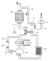
本実施形態では、本発明をEGRクーラに適用した例を説明する。図1に、EGRクーラが用いられる排気再循環装置の模式図を示す。図1に示す排気再循環装置では、エンジン1の吸気経路2の途中に、例えば、エアクリーナ3、可変ターボアクチュエータ4、インタークーラ5およびインテークマニホールド6が配置され、エンジン1の排気経路7の途中に、可変ターボアクチュエータ4およびDPF(ディーゼルパティキュレートフィルタ)8が配置されており、第1の排気再循環管9が、DPF8の排気流れ下流側と、可変ターボアクチュエータ4の吸気流れ上流側とに接続され、この第1の排気再循環管9の途中に、EGRクーラ10と、EGRバルブ11が配置されている。第1の排気再循環管9は、DPF8を通過した排気ガスの一部を、エンジンの吸気側に還流させる配管である。
DESCRIPTION OF THE PREFERRED EMBODIMENTS Embodiments shown in the drawings will be described below. The fourth embodiment described below is an embodiment of the invention described in the claims. The first embodiment is a premise of the present invention, and the second, third, and fifth embodiments are It is shown as a reference example.
(First embodiment)
In this embodiment, an example in which the present invention is applied to an EGR cooler will be described. FIG. 1 shows a schematic diagram of an exhaust gas recirculation device in which an EGR cooler is used. In the exhaust gas recirculation device shown in FIG. 1, for example, an
このように、図1に示す排気再循環装置では、EGRクーラ10内に、DPF8でPM(粒子状物質)が除去された排気が導入されることから、EGRクーラ10に導入される排気ガス中の煤の量が低減される。
As described above, in the exhaust gas recirculation device shown in FIG. 1, exhaust gas from which PM (particulate matter) has been removed by the
また、図1に示す排気再循環装置は、エンジンの排気の一部を、DPF8に通過させる前に、直接、エンジンの吸気側へ還流させる第2の排気再循環管12およびその途中に配置されたEGRバルブ13を有している。第1の排気再循環管9と第2の排気再循環管12とを比較すると、第1の排気再循環管9を流れる排気の圧力は第2の排気再循環管12内よりも低圧である。したがって、図1に示す排気再循環装置は低圧EGRシステムと呼ばれ、このシステムによれば、エンジン高負荷時でもEGRを作動させることができる利点がある。
In addition, the exhaust gas recirculation device shown in FIG. 1 is arranged in the middle of the second exhaust
図2に、本実施形態のEGRクーラの側面図を示し、図3に、EGRクーラのA−A矢視方向断面図を示し、図4に、EGRクーラのB−B矢視方向断面図を示す。 2 shows a side view of the EGR cooler of the present embodiment, FIG. 3 shows a cross-sectional view of the EGR cooler in the direction of arrows AA, and FIG. 4 shows a cross-sectional view of the EGR cooler in the direction of arrows BB. Show.
EGRクーラ10は、エンジン1での燃焼により発生した排気ガスをエンジン1に再循環させる際に、その排気ガスをエンジン1の冷却水によって、冷却する排気熱交換器であり、図2〜4に示すように、主に、複数のチューブ21と、インナーフィン22と、水側タンク23と、ガス側タンク24とを備えている。これらの部材21〜44は、ステンレス製であり、ろう付けや溶接等により接合されている。
The
チューブ21は、図3、4に示すように、排気ガスが流通する排気通路21aを構成する管であり、内部を排気ガスが流れるようになっている。また、チューブ21の外部を冷却水が流れるようになっており、このチューブ21を介して、排気ガスと冷却水とを熱交換させる。冷却水としては、例えば、エンジン冷却水に用いられるものを採用できる。
As shown in FIGS. 3 and 4, the
具体的には、図3に示すように、チューブ21の排気流れ方向から見たときの断面形状は、長辺21cと短辺21dを有する扁平形状であり、長辺21c側となる扁平面21cに垂直な方向(図中上下方向)に、複数のチューブ21が積層されている。また、図3、4に示すように、本実施形態では、基本的に、隣り合うチューブ21の外壁によって、隣り合うチューブ21間に冷却水が流れる冷却水通路21bが構成されている。
Specifically, as shown in FIG. 3, the cross-sectional shape when viewed from the exhaust flow direction of the
水側タンク23は、主に、一方の水側タンク23でEGRクーラに流入した冷却水を各チューブ21に分配供給し、他方の水側タンク23で各チューブ21からの冷却水を集合回収するものである。水側タンク23は、図2、4に示すように、チューブ21のガス流れ方向両端部近傍において、積層されたチューブ21の周囲に設けられており、冷却水入口もしくは冷却水出口23aを備えている。
The water-
ガス側タンク24は、図2、4に示すように、チューブ21のガス流れ方向両端部に、それぞれ、配置されている。両ガス側タンク24は、第1の排気再循環管9に接続され、一方のガス側タンク24で、各チューブに排気ガスを分配供給し、他方のガス側タンク24で、熱交換を終えた排気ガスを各チューブ21から集合回収する。
As shown in FIGS. 2 and 4, the
インナーフィン22は、各チューブ21内に配置されており、排気ガスと冷却水との間での熱交換を促進させるものであり、チューブ21の内壁面に固定されている。以下、インナーフィン22の詳細について説明する。
The
図5に、インナーフィンの斜視図を示し、図6に、排気ガス流れ方向から見たときのインナーフィンの部分拡大図を示す。 FIG. 5 shows a perspective view of the inner fin, and FIG. 6 shows a partially enlarged view of the inner fin when viewed from the exhaust gas flow direction.
インナーフィン22は、図5、6に示すように、排気ガスの流れ方向に略垂直な断面形状、すなわち、排気ガスの流れ方向から見たときの断面形状が、凸部31を一方側と他方側に交互に位置させて曲折する波形状であって、排気ガスの流れ方向で、部分的に切り起こされた切り起こし部32を備え、排気ガスの流れ方向から見たときに、切り起こし部32によって形成される波形状部分が、排気ガスの流れ方向で隣接する波形状部分に対して、オフセットしているオフセットフィンである。このオフセットフィン22は、凸部31がチューブ21の長辺21c側の内壁面と接している。
As shown in FIGS. 5 and 6, the
このオフセットフィン22によって、チューブ21の内部が、図3に示すように、チューブ21の長辺21cに平行な方向で、複数の流路に分割(言い換えると、区画)され、さらに、チューブ21内で複数に分割された流路は、排気流れ方向で部分的にオフセットしている。すなわち、図5に示すように、チューブ21の内部を複数の流路に分割する壁部33が、排気ガスの流れ方向に沿って、千鳥状に配置されている。また、排気流れ方向でオフセットフィン22を見たとき、一方側同士、他方側同士のように、同一側の凸部31であって、排気流れ方向で隣接する凸部31同士は、ずれて配置されている。
As shown in FIG. 3, the offset
このとき、図6に示すように、オフセット距離sは、熱伝達率が高く、ガス抵抗が小さくなるように、ガス通路高さuの約半分の大きさに設定されるのが望ましい。ここで、オフセット距離sとは、排気ガスの流れ方向から見たときに、オフセットフィン22のうち、切り起こし部32によって形成される波形状部分が、排気ガスの流れ方向で隣接する波形状部分に対して、排気ガスの流れ方向に略垂直な断面形状にて同一側で隣り合う凸部31が並ぶ方向で、ずれているときのずれ長さのことであり、言い換えると、隣り合う一方側と他方側の凸部31間に位置する壁部33と、その壁部33に対して位置ずれしている切り起こし部32の壁部33とのチューブ21の長辺21cに平行な方向での間隔のことである。
At this time, as shown in FIG. 6, the offset distance s is preferably set to about half the gas passage height u so that the heat transfer coefficient is high and the gas resistance is small. Here, the offset distance s is a wave-shaped portion where the wave-shaped portion formed by the cut-and-raised
なお、オフセットフィン22の排気ガスの流れ方向での断面形状については、凸部31の頂点に直線状部分を含む形状と含まない形状のどちらでも良い。
The cross-sectional shape of the offset
このオフセットフィン22は、プレス加工により、平板を波形状に折り曲げ、さらに、プレス加工により、切り起こし部32となる部分を起こすことで製造される。なお、切り起こし部32となる部分を起こす方法としては、起こす前に、波状にする前にあらかじめスリットを入れておく方法や、板の両面をプレス機でプレスすることにより、切る、起こす、を同時に行ってもよい。また、フィンの成形はローラ加工でも良く、またローラ加工とプレス加工両方の組み合わせでも良い。
The offset
このような構造のオフセットフィン22では、図5、6に示すように、排気ガスの流れ方向から見た断面形状にて、一方側同士もしくは他方側同士のように、一方側と他方側のうちの同一側で、隣り合う凸部31の中心同士の距離であるフィンピッチfpと、一方側の凸部から他方側の凸部までの距離であるフィン高さfhの大きさ等の仕様によって、EGRクーラ10の性能が決まる。なお、フィン高さfhは、オフセットフィン22が接触しているチューブ21の内壁面に対して垂直な方向での距離であり、チューブ21の積層方向でのチューブ21の内径と同等である。
In the offset
そこで、本発明者は、オフセットフィン22の最適仕様について検討した。本実施形態では、フィンピッチfpおよびフィン高さfhが種々の大きさである上記した構造のEGRクーラ10を作製し、所定条件でガスおよび冷却水を流したときのチューブ21の内部を流れる排気ガスの圧力損失の大きさ、チューブ21の外部を流れる冷却水の通水抵抗の大きさ、チューブ21の内部での目詰まりの有無、EGRクーラの放熱性能を評価し、この結果より、最適仕様を決定した。なお、所定条件は、ガス入口温度Tg1:400℃、ガス流量:30g/s、ガス入口圧力Pg1:50kPa、冷却水入口温度Tw1:80℃、冷却水流量:10L/minである。
Therefore, the present inventor examined the optimum specification of the offset
図7に、フィン高さfhと圧力損失比(ΔPg比)との関係を示す。なお、圧力損失ΔPgとは、ガス側タンク14のガス入口でのガス圧力Pg1とガス出口でのガス圧力Pg2との差であり、ΔPg比とは、それぞれの条件のときの圧力損失ΔPgのうち、最大値を基準値100としたときの比率(%)である。
FIG. 7 shows the relationship between the fin height fh and the pressure loss ratio (ΔPg ratio). The pressure loss ΔPg is the difference between the gas pressure Pg1 at the gas inlet of the
また、このとき用いたオフセットフィン22の条件は、オフセットフィン22の板厚t:0.2mm、フィンピッチfp:5mm、7mm、切り起こし部32の排気流れ方向での長さL:1mm、5mm、曲率半径R:0.2mmである。なお、以下では、切り起こし部32の排気流れ方向での長さLをセグメント長さLと呼ぶ。また、図7中のfp5、fp7は、それぞれ、fp=5mm、fp=7mmを示し、L1、L5は、それぞれ、L=1mm、L=5mmを示しており、fp、L等の各パラメータの次に示す数字は長さを示している。このことは、他の図においても同様である。
The conditions of the offset
図7に示すように、クーラの体格は固定、すなわち、水側タンク23およびガス側タンク24の大きさは固定で、かつ、フィンピッチfpおよびセグメント長さLも、それぞれ、fp=5mm、L=1mmで固定し、フィン高さfhを小さくなる側に変更していった場合、図中のfp5、L1のように、フィン高さfhが3.5mmのときが、傾きが変わる点である変曲点となり、圧力損失の上昇変化率は、フィン高さfhが3.5mm以下のときの方が、3.5mmよりも大きいときと比較して大きくなることがわかった。
As shown in FIG. 7, the physique of the cooler is fixed, that is, the sizes of the
同様に、図中のfp5、L5のように、fp=5mm、L=5mmで固定し、フィン高さfhを小さくなる側に変更していった場合や、図中のfp7、L5のように、fp=7mm、L=5mmで固定し、フィン高さfhを小さくなる側に変更していった場合においても、フィン高さfhが3.5mmのときが変曲点となり、fh=3.5mmを境として、圧力損失の上昇率が異なっていた。 Similarly, when fixed at fp = 5 mm and L = 5 mm as in fp5 and L5 in the figure and the fin height fh is changed to a smaller side, or as in fp7 and L5 in the figure , Fp = 7 mm, L = 5 mm, and even when the fin height fh is changed to a smaller side, the inflection point is when the fin height fh is 3.5 mm, and fh = 3. The rate of increase in pressure loss was different at 5 mm.
この結果より、クーラの体格が固定で、fp、Lが同じときでは、fhが3.5mm以下のとき、圧力損失は相対的に大きく、fhが3.5mmよりも大きいとき、圧力損失は比較的小さいと言える。したがって、フィン高さfhは、3.5mmよりも大きいことが好ましいと言える。 From this result, when the physique of the cooler is fixed and fp and L are the same, when fh is 3.5 mm or less, the pressure loss is relatively large, and when fh is larger than 3.5 mm, the pressure loss is compared. It can be said that it is small. Therefore, it can be said that the fin height fh is preferably larger than 3.5 mm.
続いて、図8に、フィン高さfhと通水抵抗ΔPwとの関係を示す。なお、通水抵抗ΔPwとは、水側タンクの冷却水入口での水圧と冷却水出口での水圧との差である。また、このとき用いたオフセットフィン22の条件については、図7のときと同じである。
Next, FIG. 8 shows the relationship between the fin height fh and the water flow resistance ΔPw. The water flow resistance ΔPw is the difference between the water pressure at the cooling water inlet of the water side tank and the water pressure at the cooling water outlet. The conditions of the offset
図8に示すように、クーラの体格は固定で、かつ、冷却水通路21bの幅となるチューブ21同士の間隔が一定であるとき、フィン高さfhを大きくなる側に変更するにつれ、通水抵抗ΔPwが増加する傾向がある。そして、通水抵抗ΔPwは、冷却性能の観点より、3〜3.2kPa以上になると冷却水流量確保のため高性能ウォーターポンプが必要となり、コストアップに繋がる。したがって、フィン高さfhは、12mm以下であることが好ましく、10mm以下であることが、より好ましいと言える。
As shown in FIG. 8, when the physique of the cooler is fixed and the interval between the
また、目詰まりの有無を調べた結果、フィンピッチfpを小さくするにつれ、オフセット距離sが小さくなり、フィンの板厚tが0.2mm以下の場合では、フィンピッチfpが2mm以下のとき、オフセット距離sが小さくなりすぎてしまい、排気ガス中の煤によって、目詰まりが生じた。したがって、目詰まりの発生を抑制する観点より、フィンピッチfpは2mmよりも大きいときが良いと言える。 Further, as a result of investigating the presence or absence of clogging, as the fin pitch fp is decreased, the offset distance s is decreased. When the fin thickness t is 0.2 mm or less, the offset is obtained when the fin pitch fp is 2 mm or less. The distance s became too small, and clogging occurred due to soot in the exhaust gas. Therefore, it can be said that the fin pitch fp is preferably larger than 2 mm from the viewpoint of suppressing the occurrence of clogging.
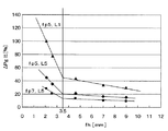
また、セグメント長さLを短くすることにより、オフセットフィン22の放熱性能を高めることができる。そこで、セグメント長さLの範囲を1≦L≦10mmとし、フィン高さfhの範囲を3.5<fh≦12とした場合のフィンピッチfpとEGRクーラの放熱性能との関係を調べた。この結果を図9に示す。なお、図9には、フィン高さfhが3.6mmもしくは12mmであり、セグメント長さLが1mmもしくは10mmである場合の結果が示されている。
Further, by shortening the segment length L, the heat dissipation performance of the offset
図9からわかるように、フィン高さfhに関わらず、セグメント長さLが10mmのときよりも1mmのときの方が、EGRクーラの放熱性能が高く、フィン高さfhが12mmで、セグメント長さLが10mmのときでは、図9中のfh12−L10からわかるように、フィンピッチfpが12mmよりも大きいときでは、市場でEGRクーラに要求される放熱性能である5.5kw/Lを満たさないが、フィンピッチfpが12mm以下であれば、市場で要求される放熱性能を満たす。 As can be seen from FIG. 9, regardless of the fin height fh, when the segment length L is 1 mm, the heat dissipation performance of the EGR cooler is higher, the fin height fh is 12 mm, and the segment length When the length L is 10 mm, as can be seen from fh12-L10 in FIG. 9, when the fin pitch fp is larger than 12 mm, the heat dissipation performance required for the EGR cooler in the market is 5.5 kw / L. However, if the fin pitch fp is 12 mm or less, the heat dissipation performance required in the market is satisfied.
したがって、フィン高さfhの範囲が3.5<fh≦12の場合では、フィンピッチfpは12mm以下が良いと言える。 Therefore, when the range of the fin height fh is 3.5 <fh ≦ 12, it can be said that the fin pitch fp is preferably 12 mm or less.
以上の検討結果により、フィンピッチfpの大きさおよびフィン高さfhを、
3.5<fh≦12
2<fp≦12
を満足する大きさとすることが好ましいと言える。
From the above examination results, the size of the fin pitch fp and the fin height fh
3.5 <fh ≦ 12
2 <fp ≦ 12
It can be said that it is preferable to make the size satisfy.
これにより、チューブ21内を流れる排気ガスの圧力損失およびチューブ21外を流れる冷却水の通水抵抗を低く抑えることができ、チューブ21内の目詰まりを抑制でき、かつ、高い放熱性能が得られる。
Thereby, the pressure loss of the exhaust gas flowing through the
(第2実施形態)
本実施形態では、第1実施形態とは異なるパラメータおよび基準により、オフセットフィン22の最適仕様を決定する場合について説明する。なお、EGRクーラ10の基本構造については、第1実施形態と同様であるため、説明を省略する。
(Second Embodiment)
In the present embodiment, a case will be described in which the optimum specification of the offset
本実施形態では、相当円直径deと、EGRガス密度比ρとの関係に基づいて、オフセットフィン22の最適仕様を決定した。
In the present embodiment, the optimum specification of the offset
ここで、相当円直径deとは、図6に示すように、オフセットフィン22の排気ガスの流れ方向に略垂直な断面形状において、一方側同士、他方側同士のように、同一側で隣り合う凸部31と凸部31との間でフィン22とチューブ21によって囲まれる斜線領域Cを円に換算したときの直径(単位:mm)を意味し、以下の式で表される。
Here, as shown in FIG. 6, the equivalent circular diameter de is adjacent on the same side, such as one side and the other side, in a cross-sectional shape substantially perpendicular to the exhaust gas flow direction of the offset
de=4×S/l
なお、Sはガス通路断面積(円の直径をDとしたときの円の断面積πD2/4に相当)である。また、lは、ぬれ縁長さ(円の直径をDとしたときの円周πDに相当)であり、フィン22とチューブ21によって構成された1つのガス流通路内壁面の長さ(内壁と気体が接する部分の長さ)である。
de = 4 × S / l
Note, S is a gas passage sectional area (corresponding to the diameter of a circle in cross-sectional area [pi] D 2/4 of the circle when a D). In addition, l is a wetting edge length (corresponding to a circumference πD when the diameter of the circle is D), and the length of the inner wall surface of one gas flow passage formed by the
また、相当円直径deの計算方法について説明する。図10に、オフセットフィン22の排気ガスの流れ方向に略垂直な方向で切断したときのオフセットフィン22の部分断面図を示す。
A method for calculating the equivalent circle diameter de will be described. FIG. 10 shows a partial cross-sectional view of the offset
図10に示すように、図6中の斜線領域Cの右側半分に相当するぬれ縁長さl/2を、5つの線分(1)〜(5)に分割することで、(3)の直線長さが0以上の時、下記の式のように、ぬれ縁長さlをフィンピッチfp、フィン高さfh、板厚t、湾曲部の曲率半径Rを用いて表すことができる。また、図6中の斜線領域Cの右側半分に相当するガス通路断面積を、4つの領域a〜dに分割することで、下記の式のように、ガス通路断面積Sをフィンピッチfp、フィン高さfh、板厚t、湾曲部の曲率半径Rを用いて表すことができる。 As shown in FIG. 10, by dividing the wetting edge length l / 2 corresponding to the right half of the hatched area C in FIG. 6 into five line segments (1) to (5), When the straight line length is 0 or more, the wetting edge length l can be expressed by using the fin pitch fp, the fin height fh, the plate thickness t, and the curvature radius R of the curved portion as in the following equation. Further, by dividing the gas passage cross-sectional area corresponding to the right half of the hatched region C in FIG. 6 into four regions a to d, the gas passage cross-sectional area S is expressed by the fin pitch fp, It can be expressed using the fin height fh, the plate thickness t, and the curvature radius R of the curved portion.
l/2=fp/2−(fp/2−(2R+t))/2…(1)
+π(R+t)/2…(2)
+fh−2(R+t)…(3)
+πR/2…(4)
+(fp/2−(2R+t))/2…(5)
S/2=(fh−t)(fp/2−(2R+t))/2…a
+(fh−(R+t))R…b
+πR2/4…c
+(R+t)2−π(R+t)2/4…d
したがって、フィンピッチfp、フィン高さfh、板厚t、湾曲部の曲率半径Rにより、相当円直径deが決定される。
l / 2 = fp / 2− (fp / 2− (2R + t)) / 2 (1)
+ Π (R + t) / 2 (2)
+ Fh-2 (R + t) (3)
+ ΠR / 2 (4)
+ (Fp / 2− (2R + t)) / 2 (5)
S / 2 = (fh−t) (fp / 2− (2R + t)) / 2... A
+ (Fh- (R + t)) R ... b
+ ΠR2 / 4 ... c
+ (R + t) 2- [pi] (R + t) 2/4 ... d
Therefore, the equivalent circular diameter de is determined by the fin pitch fp, the fin height fh, the plate thickness t, and the curvature radius R of the curved portion.
一方、EGRガス密度ρとは、EGRクーラの冷却性能と圧力損失の大きさの両方を考慮した指数であり、EGRガス密度ρ[kg/m3]は次式のように表され、ρが大きいほどEGRガスの充填率が高くなり、EGR率を上げることが可能となる。 On the other hand, the EGR gas density ρ is an index that considers both the cooling performance of the EGR cooler and the magnitude of pressure loss, and the EGR gas density ρ [kg / m 3 ] is expressed by the following equation, where ρ is The larger the ratio, the higher the EGR gas filling rate and the higher the EGR rate.
ρ=Pg2/(R・Tg2)
Pg2はガス出口絶対圧(Pa)であり、Rは気体定数=287.05J/kg・Kであり、Tg2はガス出口温度(K)である。
ρ = Pg2 / (R · Tg2)
Pg2 is the gas outlet absolute pressure (Pa), R is the gas constant = 287.05 J / kg · K, and Tg2 is the gas outlet temperature (K).
図11に、相当円直径deとEGRガス密度ρ比との関係を示す。EGRガス密度ρ比は、EGRガス密度ρの最大値を100%としたときの比率である。なお、図11は、測定条件を、ガス入口温度Tg1:400℃、ガス流量:30g/s、ガス入口圧力Pg1:50kPa、冷却水入口温度Tw1:80℃、冷却水流量:10L/minとし、フィンの板厚t:0.2mm、フィン高さfh:9mm、曲率半径R:0.2mmとしたときの測定結果に基づいて、算出した結果である。 FIG. 11 shows the relationship between the equivalent circular diameter de and the EGR gas density ρ ratio. The EGR gas density ρ ratio is a ratio when the maximum value of the EGR gas density ρ is 100%. In FIG. 11, the measurement conditions are as follows: gas inlet temperature Tg 1: 400 ° C., gas flow rate: 30 g / s, gas inlet pressure Pg 1: 50 kPa, cooling water inlet temperature Tw 1: 80 ° C., cooling water flow rate: 10 L / min. This is a calculation result based on the measurement results when the fin thickness t is 0.2 mm, the fin height fh is 9 mm, and the curvature radius R is 0.2 mm.
また、図11中の曲線(a)は、セグメント長さLを1mmとしたときの測定結果であり、図11中の曲線(b)は、Lを5mmにしたときの結果である。なお、Lの範囲が、0<L<5とき、図11中の曲線(a)と同様の結果となり、5≦L≦15のとき、図11中の曲線(b)と同様の結果となる。 Moreover, the curve (a) in FIG. 11 is a measurement result when the segment length L is 1 mm, and the curve (b) in FIG. 11 is a result when L is 5 mm. When the range of L is 0 <L <5, the result is the same as the curve (a) in FIG. 11, and when 5 ≦ L ≦ 15, the result is the same as the curve (b) in FIG. .
したがって、図11中の曲線(a)より、0<L<5のときでは、相当円直径deの大きさを、1.2≦de≦6.1とすることで、ρ比を93%以上にすることができ、1.3≦de≦5.3とすることで、ρ比を95%以上にすることができ、1.5≦de≦4.5とすることで、ρ比を97%以上にすることができることがわかる。 Therefore, from the curve (a) in FIG. 11, when 0 <L <5, the size of the equivalent circle diameter de is set to 1.2 ≦ de ≦ 6.1, so that the ρ ratio is 93% or more. By making 1.3 ≦ de ≦ 5.3, the ρ ratio can be made 95% or more, and by making 1.5 ≦ de ≦ 4.5, the ρ ratio is 97 It turns out that it can be made into% or more.
一方、図11中の曲線(b)より、5≦L≦15のときでは、相当円直径deの大きさを、1.0≦de≦4.3とすることで、ρ比を93%以上にすることができ、1.1≦de≦4.0とすることで、ρ比を95%以上にすることができ、1.3≦de≦3.5とすることで、ρ比を97%以上にすることができることがわかる。なお、上記したLとdeの単位はmmである。 On the other hand, from the curve (b) in FIG. 11, when 5 ≦ L ≦ 15, the equivalent circle diameter de is set to 1.0 ≦ de ≦ 4.3, whereby the ρ ratio is 93% or more. By making 1.1 ≦ de ≦ 4.0, the ρ ratio can be made 95% or more, and by making 1.3 ≦ de ≦ 3.5, the ρ ratio is 97 It turns out that it can be made into% or more. The unit of L and de described above is mm.
なお、図11の結果は、フィンの板厚tおよび曲率半径Rが、それぞれ、0.2mmのときの結果であるが、フィンの板厚tおよび曲率半径を実施可能な範囲で多少変更した場合においても同様の結果となる。例えば、フィンの板厚tおよび曲率半径を、それぞれ、0.1〜0.2mmで変更した場合においても同様の結果となる。 The results in FIG. 11 are the results when the plate thickness t and the curvature radius R of the fin are 0.2 mm, respectively, but when the plate thickness t and the curvature radius of the fin are slightly changed within a feasible range. The same result is obtained for. For example, the same result is obtained when the plate thickness t and the radius of curvature of the fin are each changed by 0.1 to 0.2 mm.
(第3実施形態)
本実施形態では、上記した実施形態とは異なるパラメータおよび基準により、オフセットフィン22の最適仕様を決定する場合について説明する。なお、EGRクーラ10の基本構造については、第1実施形態と同様であるため、説明を省略する。
(Third embodiment)
In the present embodiment, a case will be described in which the optimum specification of the offset
本実施形態では、セグメント長さLとEGRガス密度比ρとの関係に基づいて、オフセットフィン22の最適仕様を決定した。
In the present embodiment, the optimum specification of the offset
図12に、セグメント長さLとEGRガス密度ρ比との関係を示す。EGRガス密度ρ比は、EGRガス密度ρの最大値を100%としたときの比率である。なお、図12は、図11のときと同じ測定条件での測定結果に基づいて、算出した結果である。ただし、フィン高さfh、セグメント長さLは、図11のときと異なる。 FIG. 12 shows the relationship between the segment length L and the EGR gas density ρ ratio. The EGR gas density ρ ratio is a ratio when the maximum value of the EGR gas density ρ is 100%. In addition, FIG. 12 is the result calculated based on the measurement result on the same measurement conditions as the time of FIG. However, the fin height fh and the segment length L are different from those in FIG.
図12中の曲線(a)は、fh<7、fp≦5のときの計算結果であり、例えば、fh=4.6、fp=4.5のときの計算結果である。このときでは、セグメント長さLを、0.5<L≦65とすることで、ρ比を95%以上にすることができ、0.5<L≦25とすることで、ρ比を97%以上にすることができ、0.5<L≦7とすることで、ρ比を99%以上にすることができる。 A curve (a) in FIG. 12 is a calculation result when fh <7 and fp ≦ 5. For example, the curve (a) is a calculation result when fh = 4.6 and fp = 4.5. At this time, by setting the segment length L to 0.5 <L ≦ 65, the ρ ratio can be 95% or more, and by setting 0.5 <L ≦ 25, the ρ ratio is 97 %, And by making 0.5 <L ≦ 7, the ρ ratio can be 99% or more.
また、図12中の曲線(b)は、fh<7、5<fpのときの計算結果であり、例えば、fh=4.6、fp=5.5のときの計算結果である。このときでは、セグメント長さLを、0.5<L≦20とすることで、ρ比を95%以上にすることができ、0.5<L≦8とすることで、ρ比を97%以上にすることができ、0.5<L≦1とすることで、ρ比を99%以上にすることができる。 A curve (b) in FIG. 12 is a calculation result when fh <7, 5 <fp, for example, a calculation result when fh = 4.6 and fp = 5.5. At this time, by setting the segment length L to 0.5 <L ≦ 20, the ρ ratio can be 95% or more, and by setting 0.5 <L ≦ 8, the ρ ratio is 97 %, And by making 0.5 <L ≦ 1, the ρ ratio can be 99% or more.
また、図12中の曲線(c)は、7≦fh、fp≦5のときの計算結果であり、例えば、fh=9、fp=4.5のときの計算結果である。このときでは、セグメント長さLを、0.5<L≦50とすることで、ρ比を95%以上にすることができ、0.5<L≦15とすることで、ρ比を97%以上にすることができ、0.5<L≦4.5とすることで、ρ比を99%以上にすることができる。 A curve (c) in FIG. 12 is a calculation result when 7 ≦ fh and fp ≦ 5, and is a calculation result when fh = 9 and fp = 4.5, for example. At this time, by setting the segment length L to 0.5 <L ≦ 50, the ρ ratio can be 95% or more. By setting 0.5 <L ≦ 15, the ρ ratio is 97 %, And by making 0.5 <L ≦ 4.5, the ρ ratio can be 99% or more.
また、図12中の曲線(d)は、7≦fh、5<fpのときの計算結果であり、例えば、fh=9、fp=5.5のときの計算結果である。このときでは、セグメント長さLを、0.5<L≦15とすることで、ρ比を95%以上にすることができ、0.5<L≦6とすることで、ρ比を97%以上にすることができ、0.5<L≦1.5とすることで、ρ比を99%以上にすることができる。 A curve (d) in FIG. 12 is a calculation result when 7 ≦ fh and 5 <fp, for example, a calculation result when fh = 9 and fp = 5.5. At this time, by setting the segment length L to 0.5 <L ≦ 15, the ρ ratio can be 95% or more, and by setting 0.5 <L ≦ 6, the ρ ratio is 97 %, And by making 0.5 <L ≦ 1.5, the ρ ratio can be 99% or more.
なお、上記したfh、fp、Lの単位はmmである。また、図12の結果は、フィンの板厚tおよび曲率半径Rが、それぞれ、0.2mmのときの結果であるが、フィンの板厚tおよび曲率半径を実施可能な範囲で多少変更した場合においても同様の結果となる。例えば、フィンの板厚tおよび曲率半径を、それぞれ、0.1〜0.2mmで変更した場合においても同様の結果となる。 The unit of fh, fp, and L described above is mm. Further, the results of FIG. 12 are the results when the plate thickness t and the curvature radius R of the fin are 0.2 mm, respectively, but when the plate thickness t and the curvature radius of the fin are slightly changed within a feasible range. The same result is obtained for. For example, the same result is obtained when the plate thickness t and the radius of curvature of the fin are each changed by 0.1 to 0.2 mm.
(第4実施形態)
本実施形態では、上記した実施形態とは異なるパラメータおよび基準により、オフセットフィン22の最適仕様を決定する場合について説明する。なお、EGRクーラ10の基本構造については、第1実施形態と同様であるため、説明を省略する。
(Fourth embodiment)
In the present embodiment, a case will be described in which the optimum specification of the offset
本実施形態では、相当円直径de、セグメント長さL、フィン高さfhを用いた関数Xと、EGRガス密度比ρとの関係に基づいて、オフセットフィン22の最適仕様を決定した。
In the present embodiment, the optimum specification of the offset
図13に、関数Xと、EGRガス密度比ρとの関係を示す。この関数Xは、次式により表されるものである。 FIG. 13 shows the relationship between the function X and the EGR gas density ratio ρ. This function X is expressed by the following equation.
X=de×L0.14/fh0.18
また、図13は、フィンピッチfp、フィン高さfhおよびセグメント長さLを種々の大きさとしたときのEGRガス密度比ρの計算結果である。図中の各曲線は、fhおよびLを固定として、fpを任意の大きさとして、fpの大きさ毎にEGRガス密度比をプロットして得られたものである。横軸の値が大きくなるに連れて、fpが大きくなっており、一例として、図13中には、各曲線のfpが12mm、14mmの位置に、それぞれ、fp12、fp14と示している。具体的には、フィンピッチfpは1.5〜14mmのいずれかであり、フィン高さfhは4.6、5.6、7、9、12mmのいずれかであり、セグメント長さLは1mmもしくは10mmである。また、他の測定条件は、図11、12のときと同じである。
X = de × L 0.14 / fh 0.18
FIG. 13 shows calculation results of the EGR gas density ratio ρ when the fin pitch fp, the fin height fh, and the segment length L are various sizes. Each curve in the figure is obtained by plotting the EGR gas density ratio for each size of fp, with fh and L being fixed, fp being an arbitrary size. As the value on the horizontal axis increases, fp increases. As an example, in FIG. 13, fp of each curve is indicated as fp12 and fp14 at positions of 12 mm and 14 mm, respectively. Specifically, the fin pitch fp is any of 1.5 to 14 mm, the fin height fh is any of 4.6, 5.6, 7, 9, and 12 mm, and the segment length L is 1 mm. Or 10 mm. Other measurement conditions are the same as those in FIGS.
図13に示す結果より、関数XとEGRガス密度比ρとの関係を示す曲線は、各条件において、同様の傾向を示すことがわかる。 From the results shown in FIG. 13, it can be seen that the curve indicating the relationship between the function X and the EGR gas density ratio ρ shows the same tendency under each condition.
そして、第1実施形態で説明したように、フィンピッチfpは2<fp≦12を満たす範囲が好ましいことから、この範囲内では、図13中のfpが12mmである点をつなぐ直線からわかるように、相当円直径deおよびセグメント長さLを、1.1≦X≦4.3を満足する大きさとし、より好ましくは、1.1≦X≦3.5を満足する大きさとすることで、ρ比を93%以上にすることができる。同様に、相当円直径deおよびセグメント長さLを、1.2≦X≦3.9を満足する大きさ、より好ましくは、1.2≦X≦3.3を満足する大きさとすることで、ρ比を95%以上にすることができ、1.3≦X≦3.5を満足する大きさ、より好ましくは、1.3≦X≦2.9を満足する大きさとすることで、ρ比を97%以上にすることができる。 As described in the first embodiment, the fin pitch fp is preferably in a range satisfying 2 <fp ≦ 12. In this range, it can be seen from a straight line connecting points where fp in FIG. 13 is 12 mm. In addition, by setting the equivalent circle diameter de and the segment length L to a size that satisfies 1.1 ≦ X ≦ 4.3, and more preferably, a size that satisfies 1.1 ≦ X ≦ 3.5, The ρ ratio can be 93% or more. Similarly, by setting the equivalent circle diameter de and the segment length L to a size satisfying 1.2 ≦ X ≦ 3.9, more preferably 1.2 ≦ X ≦ 3.3. , The ρ ratio can be 95% or more, and a size satisfying 1.3 ≦ X ≦ 3.5, more preferably a size satisfying 1.3 ≦ X ≦ 2.9. The ρ ratio can be 97% or more.
なお、fp、Xの単位はmmである。また、図13の結果は、フィンの板厚tおよび曲率半径Rが、それぞれ、0.2mmのときの結果であるが、フィンの板厚tおよび曲率半径を実施可能な範囲で多少変更した場合においても同様の結果となる。例えば、フィンの板厚tおよび曲率半径を、それぞれ、0.1mm以上0.2mm未満の範囲内で変更した場合においても同様の結果となる。 The unit of fp and X is mm. The results in FIG. 13 are the results when the plate thickness t and the radius of curvature R of the fin are 0.2 mm, respectively, but when the plate thickness t and the radius of curvature of the fin are slightly changed within a feasible range. The same result is obtained for. For example, the same result is obtained when the plate thickness t and the radius of curvature of the fin are changed within a range of 0.1 mm or more and less than 0.2 mm, respectively.
(第5実施形態)
第1実施形態では、図6に示すオフセット量sについて、相対的な大きさとして、ガス通路高さuの約半分の大きさに設定されるのが望ましいと説明したが、本実施形態では、オフセット距離sの絶対的な大きさについて説明する。なお、以下では、なお、オフセット距離s以外のEGRクーラ10の基本構造については、第1実施形態と同様であるため、説明を省略する。
(Fifth embodiment)
In the first embodiment, the offset amount s illustrated in FIG. 6 has been described as being preferably set to a relative size that is approximately half the gas passage height u. However, in the present embodiment, The absolute size of the offset distance s will be described. In the following description, the basic structure of the
図14(a)に、第1実施形態で説明した構成のEGRクーラ内を排気ガスが通過する際に、オフセットフィンの表面に堆積する排気ガス中の煤等のPM(粒子状物質)の堆積厚さと時間との関係を調査した結果を示す。また、図14(b)に、排気ガス流れとチューブ21の長辺21cに平行な方向で切断したときのオフセットフィン22の断面図を示す。図14(b)は、排気ガスの流れ方向に沿って、千鳥状に配置されているオフセットフィン22の壁部33を示しており、図14(b)の左右方向が排気ガスの流れ方向である。
FIG. 14A shows the accumulation of PM (particulate matter) such as soot in the exhaust gas that accumulates on the surface of the offset fin when the exhaust gas passes through the EGR cooler having the configuration described in the first embodiment. The result of investigating the relationship between thickness and time is shown. FIG. 14B is a cross-sectional view of the offset
図14(b)に示すように、EGRクーラ内を排気ガスが通過すると、オフセットフィン22の表面上にPM41が堆積する。そして、図14(a)中の破線で示すように、PM41は、時間が経過するにつれて平均堆積厚さが増加し、8時間以上経過した場合では、PM41の平均堆積厚さが、約0.25mmの大きさで、ほぼ一定となることがわかった。
As shown in FIG. 14B, when the exhaust gas passes through the EGR cooler,
このことから、オフセット距離sを0.5mmに設定した場合、排気ガスが通過し始めて8時間以上経過すると、図14(b)に示すように、オフセットフィン22の表面上に堆積するPM41の平均堆積厚さが0.25mmとなって、オフセットフィン22のうち、排気ガスの流れ方向に隣接する部分同士の境界付近で、排気ガスの通路が塞がってしまう。
From this, when the offset distance s is set to 0.5 mm, the average of
したがって、目詰まりが生じないようにするという観点より、オフセット距離sは、0.5mmより大きくすることが必要である。なお、本実施形態は、上記した第1〜第4実施形態と組み合わせることが可能である。 Therefore, the offset distance s needs to be larger than 0.5 mm from the viewpoint of preventing clogging. In addition, this embodiment can be combined with the above-described first to fourth embodiments.
(他の実施形態)
(1)上記した第5実施形態では、オフセット距離sの大きさについて説明したが、図6中の同一側で隣り合う凸部31と凸部31との間でフィン22とチューブ21によって囲まれる斜線領域Cに対するオフセット領域Dの割合をパラメータとして、オフセットフィン22の最適仕様を決定することもできる。
(Other embodiments)
(1) In the fifth embodiment described above, the magnitude of the offset distance s has been described. However, the
すなわち、図6に示すように、オフセットフィン22を排気ガス流れ方向で見たときに、排気流れ方向で隣りあう凸部31に対してオフセットした部分をオフセット領域Dと呼ぶとすると、図6中の斜線領域Cの面積に対するオフセット領域Dの面積の割合が、25%より小さい場合では、オフセット部Dを排気ガスが通過する際のガス抵抗が大きく、圧力損失が大きくなってしまうので、オフセット領域Dの割合を、25%以上とすることが良い。
That is, as shown in FIG. 6, when the offset
また、オフセット領域Dの面積割合を、40%よりも大きくしようとした場合では、例えば、オフセットフィン22を、プレス加工により、平板を波形状に折り曲げ、切り起こし部32となる部分を起こすことで製造したときに、切り起こされた残りの部分のフィンピッチfpに平行な方向での長さが短くなり、切り起こし部32の根元の部分が切れやすくなってしまうので、オフセット領域Dの割合を、40%以下とすることが良い。
Further, in the case where the area ratio of the offset region D is to be made larger than 40%, for example, the offset
したがって、斜線領域Cに対するオフセット領域Dの面積割合としては、25%以上40%以下とすることが良い。本実施形態は、上記した各実施形態と組み合わせることが可能である。 Therefore, the area ratio of the offset region D to the hatched region C is preferably 25% or more and 40% or less. This embodiment can be combined with the above-described embodiments.
なお、上記したオフセット領域Dの面積は、言い換えると、図6のように、切り起こし部32によって形成される波形状部分と、これに排気ガスの流れ方向で隣接する波形状部分を、オフセットフィン22の排気ガスの流れ方向に略垂直な面に投影したとき、両部分の壁部33と壁部33で囲まれる排気ガス通路部分の面積のことである。
In other words, the area of the offset region D described above is obtained by dividing the wave shape portion formed by the cut and raised
(2)図15に、本発明の他の実施形態における排気再循環装置の模式図を示す。なお、図15では、図1と同様の構成部に図1と同一の符号を付している。 (2) FIG. 15 shows a schematic diagram of an exhaust gas recirculation device according to another embodiment of the present invention. In FIG. 15, the same components as those in FIG. 1 are denoted by the same reference numerals as those in FIG.
上記した各実施形態では、図1に示す排気再循環装置における第1の排気再循環管9の途中に配置されるEGRクーラ10に本発明を適用した例を説明したが、図15に示すように、エンジン1の排気の一部を、DPF8に通過させる前に、直接、エンジン1の吸気側へ還流させる第2の排気再循環管12の途中に配置したEGRクーラ10に対して、本発明を適用することもできる。
In each of the above-described embodiments, the example in which the present invention is applied to the
(3)上記した各実施形態では、EGRガスクーラを例として説明したが、材質がステンレスである他の排気熱交換器においても、本発明を適用できる。例えば、外気に排出される排気ガスと冷却水との間で熱交換させ、冷却水を加熱する排熱回収熱交換器に、本発明を適用できる。 (3) In the above-described embodiments, the EGR gas cooler has been described as an example. However, the present invention can also be applied to other exhaust heat exchangers made of stainless steel. For example, the present invention can be applied to an exhaust heat recovery heat exchanger in which heat is exchanged between exhaust gas discharged to the outside air and cooling water to heat the cooling water.
1…エンジン、8…DPF、9…第1の排気再循環管、10…EGRクーラ、
21…チューブ、22…オフセット型インナーフィン。
DESCRIPTION OF
21 ... Tube, 22 ... Offset type inner fin.
Claims (3)
内部を前記排気ガスが流れ、外部を前記冷却水が流れるステンレス製のチューブ(21)と、
前記チューブ内に配置され、前記排気ガスと前記冷却水との間での熱交換を促進させるステンレス製のインナーフィン(22)とを備え、
前記インナーフィン(22)は、前記排気ガスの流れ方向に略垂直な断面形状が、凸部(31)を一方側と他方側に交互に位置させて曲折する波形状であって、前記排気ガスの流れ方向に平行な方向で部分的に切り起こされた切り起こし部(32)を備えるオフセットフィンであり、
前記断面形状にて、前記一方側と前記他方側のうちの同一側で隣り合う前記凸部の中心同士の距離であるフィンピッチの大きさをfpとし、前記一方側と前記他方側のうちの同一側で隣り合う前記凸部と前記凸部との間でフィンによって囲まれた領域の相当円直径をdeとし、前記切り起こし部の排気流れ方向での長さをLとし、前記断面形状における前記一方側の凸部から前記他方側の凸部までの距離であるフィン高さをfhとしたときに、
前記フィンピッチの大きさが、
2<fp≦12(単位:mm)
を満足する大きさであり、
前記切り起こし部の排気流れ方向での長さLが、
fh<7、fp≦5のとき、0.5<L≦7(単位:mm)、
fh<7、5<fpのとき、0.5<L≦1(単位:mm)、
7≦fh、fp≦5のとき、0.5<L≦4.5(単位:mm)、または
7≦fh、5<fpのとき、0.5<L≦1.5(単位:mm)
であって、
さらに、
X=de×L0.14/fh0.18としたときに、
前記相当円直径deおよび前記切り起こし部の排気流れ方向での長さLが、前記粒子状物質が前記インナーフィン(22)に堆積することを抑制するために、
1.1≦X≦4.3
を満足する大きさになっていることを特徴とする排気熱交換器。 Engine performs heat exchange with the cooling water for cooling the exhaust gas and the exhaust gas containing particulate matter generated by combustion in (1), wherein the exhaust gas after the heat exchange engine (1) In the exhaust heat exchanger flowing out to the side ,
Internal the exhaust gas flow, the stainless steel tubing through the external said cooling water (21),
Wherein arranged in the tube, and a stainless steel inner fin to promote heat exchange (22) between the said cooling water and the exhaust gas,
The inner fin (22) is approximately the cross-sectional shape perpendicular to the flow direction of the exhaust gas, a wave shape which bent by alternately positioned protrusions (31) on one side and the other side, the exhaust gas An offset fin comprising a cut-and-raised part (32) partially cut and raised in a direction parallel to the flow direction of
In the cross-sectional shape, the size of the fin pitch, which is the distance between the centers of the convex portions adjacent to each other on the same side of the one side and the other side , is fp , The equivalent circular diameter of the region surrounded by the fins between the convex portions adjacent to each other on the same side is de, the length of the cut-and-raised portion in the exhaust flow direction is L, and the cross-sectional shape is It said one fin height is the distance from the convex portion of the side to the convex portion of the other side is taken as fh,
The size of the fin pitch is
2 <fp ≦ 12 (unit: mm)
Is a size that satisfies
The length L of the cut and raised portion in the exhaust flow direction is
When fh <7 and fp ≦ 5, 0.5 <L ≦ 7 (unit: mm),
When fh <7, 5 <fp, 0.5 <L ≦ 1 (unit: mm),
When 7 ≦ fh and fp ≦ 5, 0.5 <L ≦ 4.5 (unit: mm), or
When 7 ≦ fh and 5 <fp, 0.5 <L ≦ 1.5 (unit: mm)
Because
further,
When X = de × L 0.14 / fh 0.18 ,
In order to suppress the equivalent circular diameter de and the length L of the cut and raised portion in the exhaust flow direction from being deposited on the inner fin (22),
1.1 ≦ X ≦ 4.3
Exhaust heat exchanger, characterized in has become sized Rukoto that satisfies.
1.2≦X≦3.9
を満足する大きさであることを特徴とする請求項1に記載の排気熱交換器。 The equivalent circular diameter and the length of the cut and raised portion in the exhaust flow direction are:
1.2 ≦ X ≦ 3.9
The exhaust heat exchanger according to claim 1 , wherein the exhaust heat exchanger has a size satisfying.
1.3≦X≦3.5
を満足する大きさであることを特徴とする請求項1に記載の排気熱交換器。 The equivalent circular diameter and the length of the cut and raised portion in the exhaust flow direction are:
1.3 ≦ X ≦ 3.5
The exhaust heat exchanger according to claim 1 , wherein the exhaust heat exchanger has a size satisfying.
Priority Applications (1)
| Application Number | Priority Date | Filing Date | Title |
|---|---|---|---|
| JP2007182056A JP4240136B2 (en) | 2006-07-11 | 2007-07-11 | Exhaust heat exchanger |
Applications Claiming Priority (2)
| Application Number | Priority Date | Filing Date | Title |
|---|---|---|---|
| JP2006190428 | 2006-07-11 | ||
| JP2007182056A JP4240136B2 (en) | 2006-07-11 | 2007-07-11 | Exhaust heat exchanger |
Publications (3)
| Publication Number | Publication Date |
|---|---|
| JP2008039380A JP2008039380A (en) | 2008-02-21 |
| JP2008039380A5 JP2008039380A5 (en) | 2008-08-07 |
| JP4240136B2 true JP4240136B2 (en) | 2009-03-18 |
Family
ID=39174589
Family Applications (1)
| Application Number | Title | Priority Date | Filing Date |
|---|---|---|---|
| JP2007182056A Active JP4240136B2 (en) | 2006-07-11 | 2007-07-11 | Exhaust heat exchanger |
Country Status (1)
| Country | Link |
|---|---|
| JP (1) | JP4240136B2 (en) |
Cited By (1)
| Publication number | Priority date | Publication date | Assignee | Title |
|---|---|---|---|---|
| US10392979B2 (en) | 2015-06-30 | 2019-08-27 | Tokyo Radiator Mfg. Co., Ltd. | Inner fin for heat exchanger |
Families Citing this family (13)
| Publication number | Priority date | Publication date | Assignee | Title |
|---|---|---|---|---|
| US8167028B2 (en) * | 2008-01-03 | 2012-05-01 | Denso Corporation | Heat exchanger fin with planar crests and troughs having slits |
| JP5226393B2 (en) * | 2008-06-12 | 2013-07-03 | 株式会社ティラド | Heat exchanger |
| JP5141585B2 (en) * | 2009-02-13 | 2013-02-13 | トヨタ自動車株式会社 | Foreign matter collecting device with cooler |
| JP5321271B2 (en) | 2009-06-17 | 2013-10-23 | 株式会社デンソー | Heat exchanger for high temperature gas cooling |
| JP5609339B2 (en) * | 2010-07-09 | 2014-10-22 | 株式会社デンソー | Oil cooler |
| JP5887115B2 (en) | 2011-11-30 | 2016-03-16 | 東京ラヂエーター製造株式会社 | Inner fin |
| JP5886637B2 (en) * | 2012-01-24 | 2016-03-16 | 京セラ株式会社 | Cooling substrate, element storage package, and mounting structure |
| DE102012104707A1 (en) * | 2012-05-31 | 2013-12-05 | Benteler Automobiltechnik Gmbh | Method for producing an exhaust gas heat exchanger |
| JP2014074562A (en) * | 2012-10-05 | 2014-04-24 | Calsonic Kansei Corp | Offset fin of heat exchanger and forming method of the same |
| JP6003778B2 (en) | 2013-04-03 | 2016-10-05 | 株式会社デンソー | Manufacturing method of heat exchanger |
| JP6333571B2 (en) * | 2014-02-10 | 2018-05-30 | 三菱重工オートモーティブサーマルシステムズ株式会社 | Offset fin for heat exchanger and refrigerant heat exchanger using the same |
| JP5884055B2 (en) | 2014-05-09 | 2016-03-15 | パナソニックIpマネジメント株式会社 | Heat exchanger and offset fin for heat exchanger |
| CN113950605A (en) * | 2019-07-02 | 2022-01-18 | 株式会社T.Rad | Heat exchanger |
-
2007
- 2007-07-11 JP JP2007182056A patent/JP4240136B2/en active Active
Cited By (1)
| Publication number | Priority date | Publication date | Assignee | Title |
|---|---|---|---|---|
| US10392979B2 (en) | 2015-06-30 | 2019-08-27 | Tokyo Radiator Mfg. Co., Ltd. | Inner fin for heat exchanger |
Also Published As
| Publication number | Publication date |
|---|---|
| JP2008039380A (en) | 2008-02-21 |
Similar Documents
| Publication | Publication Date | Title |
|---|---|---|
| JP4240136B2 (en) | Exhaust heat exchanger | |
| US20080011464A1 (en) | Exhaust gas heat exchanger | |
| US7478630B2 (en) | Device and method for cooling exhaust gas | |
| KR100895483B1 (en) | Heat exchanger tube | |
| KR101569829B1 (en) | Heat exchanger having wavy fin plate for reducing differential pressure of egr gas | |
| US9395121B2 (en) | Heat exchanger having convoluted fin end and method of assembling the same | |
| JP4207331B2 (en) | Double heat exchanger | |
| JP4674602B2 (en) | Heat exchanger | |
| JP3774843B2 (en) | Multi-tube heat exchanger | |
| JP5609339B2 (en) | Oil cooler | |
| US20090250201A1 (en) | Heat exchanger having a contoured insert and method of assembling the same | |
| US8136578B2 (en) | Heat exchanger for EGR-gas | |
| EP1505360A1 (en) | Heat transfer pipe and heat exchange incorporating such heat transfer pipe | |
| JP2008039380A5 (en) | ||
| US7866305B2 (en) | Flow channel, heat exchanger, exhaust gas recirculation system, charge air supply system, use of a heat exchanger | |
| JP6011481B2 (en) | Heat exchanger fins | |
| JP5803768B2 (en) | Heat exchanger fins and heat exchangers | |
| JP5784267B2 (en) | Flat heat transfer tube for EGR cooler and EGR cooler using this flat heat transfer tube | |
| JP4069570B2 (en) | Exhaust heat exchanger | |
| JP2008145024A (en) | Manufacturing method of flat heat transfer tube, flat heat transfer tube obtained by method, and gas cooling device incorporating flat heat transfer tube | |
| JP2718193B2 (en) | Heat exchanger | |
| JP4670610B2 (en) | Intercooler | |
| JP2015078819A (en) | Inner fin | |
| EP3575728B1 (en) | A core of a heat exchanger comprising corrugated fins | |
| JP2005061648A (en) | Heat exchanger |
Legal Events
| Date | Code | Title | Description |
|---|---|---|---|
| A521 | Written amendment |
Free format text: JAPANESE INTERMEDIATE CODE: A523 Effective date: 20080623 |
|
| A621 | Written request for application examination |
Free format text: JAPANESE INTERMEDIATE CODE: A621 Effective date: 20080623 |
|
| A871 | Explanation of circumstances concerning accelerated examination |
Free format text: JAPANESE INTERMEDIATE CODE: A871 Effective date: 20080623 |
|
| A131 | Notification of reasons for refusal |
Free format text: JAPANESE INTERMEDIATE CODE: A131 Effective date: 20080909 |
|
| A521 | Written amendment |
Free format text: JAPANESE INTERMEDIATE CODE: A523 Effective date: 20081105 |
|
| TRDD | Decision of grant or rejection written | ||
| A975 | Report on accelerated examination |
Free format text: JAPANESE INTERMEDIATE CODE: A971005 Effective date: 20081126 |
|
| A01 | Written decision to grant a patent or to grant a registration (utility model) |
Free format text: JAPANESE INTERMEDIATE CODE: A01 Effective date: 20081202 |
|
| A01 | Written decision to grant a patent or to grant a registration (utility model) |
Free format text: JAPANESE INTERMEDIATE CODE: A01 |
|
| A61 | First payment of annual fees (during grant procedure) |
Free format text: JAPANESE INTERMEDIATE CODE: A61 Effective date: 20081215 |
|
| FPAY | Renewal fee payment (event date is renewal date of database) |
Free format text: PAYMENT UNTIL: 20120109 Year of fee payment: 3 |
|
| R150 | Certificate of patent or registration of utility model |
Free format text: JAPANESE INTERMEDIATE CODE: R150 |
|
| FPAY | Renewal fee payment (event date is renewal date of database) |
Free format text: PAYMENT UNTIL: 20120109 Year of fee payment: 3 |
|
| FPAY | Renewal fee payment (event date is renewal date of database) |
Free format text: PAYMENT UNTIL: 20120109 Year of fee payment: 3 |
|
| FPAY | Renewal fee payment (event date is renewal date of database) |
Free format text: PAYMENT UNTIL: 20130109 Year of fee payment: 4 |
|
| FPAY | Renewal fee payment (event date is renewal date of database) |
Free format text: PAYMENT UNTIL: 20130109 Year of fee payment: 4 |
|
| FPAY | Renewal fee payment (event date is renewal date of database) |
Free format text: PAYMENT UNTIL: 20130109 Year of fee payment: 4 |
|
| FPAY | Renewal fee payment (event date is renewal date of database) |
Free format text: PAYMENT UNTIL: 20140109 Year of fee payment: 5 |
|
| RVTR | Cancellation of determination of trial for invalidation | ||
| FPAY | Renewal fee payment (event date is renewal date of database) |
Free format text: PAYMENT UNTIL: 20140109 Year of fee payment: 5 |
|
| FPAY | Renewal fee payment (event date is renewal date of database) |
Free format text: PAYMENT UNTIL: 20140109 Year of fee payment: 5 |