JP4240095B2 - Sealed lamp device and projector - Google Patents
Sealed lamp device and projector Download PDFInfo
- Publication number
- JP4240095B2 JP4240095B2 JP2006254815A JP2006254815A JP4240095B2 JP 4240095 B2 JP4240095 B2 JP 4240095B2 JP 2006254815 A JP2006254815 A JP 2006254815A JP 2006254815 A JP2006254815 A JP 2006254815A JP 4240095 B2 JP4240095 B2 JP 4240095B2
- Authority
- JP
- Japan
- Prior art keywords
- case body
- hollow case
- discharge lamp
- opening
- lamp burner
- Prior art date
- Legal status (The legal status is an assumption and is not a legal conclusion. Google has not performed a legal analysis and makes no representation as to the accuracy of the status listed.)
- Expired - Fee Related
Links
Images


Classifications
-
- G—PHYSICS
- G03—PHOTOGRAPHY; CINEMATOGRAPHY; ANALOGOUS TECHNIQUES USING WAVES OTHER THAN OPTICAL WAVES; ELECTROGRAPHY; HOLOGRAPHY
- G03B—APPARATUS OR ARRANGEMENTS FOR TAKING PHOTOGRAPHS OR FOR PROJECTING OR VIEWING THEM; APPARATUS OR ARRANGEMENTS EMPLOYING ANALOGOUS TECHNIQUES USING WAVES OTHER THAN OPTICAL WAVES; ACCESSORIES THEREFOR
- G03B21/00—Projectors or projection-type viewers; Accessories therefor
- G03B21/14—Details
- G03B21/16—Cooling; Preventing overheating
-
- H—ELECTRICITY
- H01—ELECTRIC ELEMENTS
- H01J—ELECTRIC DISCHARGE TUBES OR DISCHARGE LAMPS
- H01J61/00—Gas-discharge or vapour-discharge lamps
- H01J61/02—Details
- H01J61/025—Associated optical elements
-
- H—ELECTRICITY
- H01—ELECTRIC ELEMENTS
- H01J—ELECTRIC DISCHARGE TUBES OR DISCHARGE LAMPS
- H01J61/00—Gas-discharge or vapour-discharge lamps
- H01J61/02—Details
- H01J61/52—Cooling arrangements; Heating arrangements; Means for circulating gas or vapour within the discharge space
-
- H—ELECTRICITY
- H01—ELECTRIC ELEMENTS
- H01J—ELECTRIC DISCHARGE TUBES OR DISCHARGE LAMPS
- H01J61/00—Gas-discharge or vapour-discharge lamps
- H01J61/84—Lamps with discharge constricted by high pressure
- H01J61/86—Lamps with discharge constricted by high pressure with discharge additionally constricted by close spacing of electrodes, e.g. for optical projection
Description
本発明は、高圧放電ランプの一種であるメタルハライドランプなどの密閉型ランプ装置およびこれを用いたプロジェクターに関する。 The present invention relates to a sealed lamp device such as a metal halide lamp which is a kind of high-pressure discharge lamp, and a projector using the same.
従来より、プロジェクターの照明光源としては、超高圧水銀ランプあるいはメタルハライドランプなどの放電ランプバーナーに凹面反射鏡を組合せた光源ユニットが使用されている。
近年、前記凹面反射鏡の前方の光出射側開口に透光性材料からなる前面板が備え付けられた、いわゆる密閉型のランプ装置が一般に利用されている。
Conventionally, a light source unit in which a concave reflecting mirror is combined with a discharge lamp burner such as an ultra-high pressure mercury lamp or a metal halide lamp has been used as an illumination light source for a projector.
In recent years, a so-called hermetic lamp device in which a front plate made of a translucent material is provided in a light emission side opening in front of the concave reflecting mirror is generally used.
放電ランプバーナーは、光だけでなく多量の熱が放出されるため、長時間点灯使用していると、放電ランプバーナーやその近傍が過熱して、放電ランプバーナーの破裂や失透、凹面反射鏡内面の割れなどを生じることがある。
密閉型ランプ装置は、内蔵された放電ランプバーナーが万が一破裂したときに、その破裂音の漏洩や破片などが外部周辺に飛散するのが防止される他、外気に含まれる塵や埃などの侵入が回避され、輝度の低下が防止される利点がある。
Since the discharge lamp burner emits not only light but also a large amount of heat, if it is used for a long time, the discharge lamp burner and its vicinity will overheat, causing the discharge lamp burner to rupture and devitrify, and a concave reflector. Internal cracks may occur.
In the sealed lamp unit, in the unlikely event that the built-in discharge lamp burner ruptures, leakage of the rupture sound or debris is prevented from scattering around the outside, and intrusion of dust or dirt contained in the outside air Is avoided, and a reduction in luminance is prevented.
しかしながら、放電ランプバーナーの発光効率や寿命の観点から、温度を所定の温度範囲内に収まるようにすることが必要とされるため、放電ランプバーナーに、シロッコファンや軸流ファンなどの送風ファンにより風を吹き当て空冷している。なお、このような従来技術に類似のものが、以下に示す特許文献1に開示されている。
ところで、明るい室内で見る場合や、スクリーンが大型化する場合、また視野角改善の為に正面以外にも光を分散させる場合、放電ランプバーナーの輝度の向上、即ち出力の増大化がなされている。このような映像の明るさに対する要求から、放電ランプバーナーがより高輝度化されることで、排熱すべき熱量も増加の一途を辿っている。 By the way, when viewed in a bright room, when the screen is enlarged, or when light is dispersed in addition to the front to improve the viewing angle, the brightness of the discharge lamp burner is improved, that is, the output is increased. . Due to the demand for the brightness of the image, the amount of heat to be exhausted has been steadily increasing as the discharge lamp burner has higher brightness.
そこで、放電ランプバーナーの排熱を促進するため、送風ファンの回転数を上げたり、より出力の大きな送風ファンを用いることが考えられるが、その結果、許容できない送風音を伴う可能性があり、プロジェクターとしての商品価値を大きく損なう恐れがある。
また、密閉型ランプ装置の外部に、熱交換器を有する循環管路を形成し、放熱性能を向上させたものがあるが、部品点数の増大やプロジェクターの大型化を招き、コスト高になるという事情がある。
Therefore, in order to promote the exhaust heat of the discharge lamp burner, it is conceivable to increase the rotational speed of the blower fan or use a blower fan with a larger output, but as a result, there may be an unacceptable blown sound, There is a risk that the commercial value of the projector will be greatly impaired.
In addition, some of the sealed lamp devices have a circulation line with a heat exchanger to improve the heat dissipation performance, but this increases the number of components and the projector size, which increases costs. There are circumstances.
本発明の技術的課題は、前記のような事情に鑑みてなされたものであり、その目的は、低コストで放熱性(排熱性)を向上することができ、しかもコンパクトな密閉型ランプ装置およびこれを用いたプロジェクターを提供することにある。 The technical problem of the present invention has been made in view of the circumstances as described above, and an object thereof is to improve heat dissipation (exhaust heat) at a low cost, and to achieve a compact sealed lamp device and It is to provide a projector using this.
前記目的を達成するため、本発明の密閉型ランプ装置は、放電ランプバーナーと、前方が開口され、光軸が前記放電ランプバーナーの光軸に一致するように設けられ、前記放電ランプバーナーの放射光を開口側に反射する凹面反射鏡と、前面に開口部を有し、前記凹面反射鏡の開口が臨む中空ケース体と、前記中空ケース体の開口部を閉塞し、前記放射光を出射する前面板とを備え、前記中空ケース体は、前記凹面反射鏡の開口幅より幅広であって、前記放電ランプバーナーが占有する密閉容積が大きくなるように形成されるとともに、前記中空ケース体の内部に、空気の鉛直対流を前記中空ケース体の内壁全域に渡って誘導させる整流板が設けられ、この整流板は、前記中空ケース体の左右両側壁の近傍に間隔を置いて延設された一対の帯板からなるとともに、この一対の帯板の上部間に、前記帯板より幅狭の中間板が架設されるように構成した。 In order to achieve the above object, a sealed lamp device according to the present invention is provided with a discharge lamp burner, a front opening, and an optical axis that coincides with the optical axis of the discharge lamp burner. A concave reflecting mirror that reflects light to the opening side, a hollow case body that has an opening on the front surface, the opening of the concave reflecting mirror faces, the opening of the hollow case body is closed, and the emitted light is emitted and a front plate, wherein the hollow case body, a wider than the opening width of the concave reflector, together with the discharge lamp burner is formed so as to enclosed volume occupied is increased, the interior of the hollow case body Further, a rectifying plate for guiding vertical convection of air over the entire inner wall of the hollow case body is provided, and the rectifying plates are extended in the vicinity of the left and right side walls of the hollow case body with a space therebetween. Band Together consist of, between the upper of the pair of strips, the intermediate plate narrow than the strip is configured to be bridged.
このような構成の密閉型ランプ装置では、凹面反射鏡の開口幅より幅広の中空ケース体が設けられ、放電ランプバーナーが占有する密閉容積を大きくしたことで、放熱性が向上し、低コストで温度低減効果が得られる。 In the sealed lamp device having such a configuration, a hollow case body wider than the opening width of the concave reflecting mirror is provided, and the sealed volume occupied by the discharge lamp burner is increased, thereby improving heat dissipation and reducing the cost. A temperature reduction effect is obtained.
また、本発明のプロジェクターは、密閉型ランプ装置を有し、この密閉型ランプ装置は、放電ランプバーナーと、前方が開口され、光軸が前記放電ランプバーナーの光軸に一致するように設けられ、前記放電ランプバーナーの放射光を開口側に反射する凹面反射鏡とを備えている。また、前面に開口部を有し、前記凹面反射鏡の開口が臨む中空ケース体と、前記中空ケース体の開口部を閉塞し、前記放射光を出射する前面板と、前記中空ケース体の内部に設けられ、空気の鉛直対流を前記中空ケース体の内壁全域に渡って誘導させる整流板とを備えている。前記中空ケース体は、前記凹面反射鏡の開口幅より幅広に形成され、前記放電ランプバーナーが占有する密閉容積を大きくしている。さらに、前記放電ランプバーナーを冷却するランプ冷却装置と、投射レンズや反射ミラーを有する光学ユニットとを有して構成されている。 In addition, the projector of the present invention has a sealed lamp device, and this sealed lamp device is provided with a discharge lamp burner, the front is opened, and the optical axis coincides with the optical axis of the discharge lamp burner. And a concave reflecting mirror for reflecting the emitted light of the discharge lamp burner to the opening side. A hollow case body having an opening on a front surface thereof, the opening of the concave reflector facing the opening; a front plate for closing the opening of the hollow case body and emitting the radiated light; and an interior of the hollow case body And a rectifying plate for guiding the vertical convection of air over the entire inner wall of the hollow case body. The hollow case body is formed wider than the opening width of the concave reflecting mirror, and the sealed volume occupied by the discharge lamp burner is increased. In addition, the apparatus includes a lamp cooling device that cools the discharge lamp burner, and an optical unit that includes a projection lens and a reflecting mirror.
このプロジェクターは、放電ランプバーナーの占有密閉容積が大きくなり、しかも整流板によって鉛直対流が中空ケース体の全域に対流するようになるので、放熱性がより向上する。このようなプロジェクターは、低コスト、かつコンパクトな構造で実現される。 In this projector, the occupied sealed volume of the discharge lamp burner is increased, and the vertical convection is convected by the rectifying plate to the entire area of the hollow case body, so that the heat dissipation is further improved. Such a projector is realized with a low-cost and compact structure.
本発明によれば、密閉型ランプ装置の放熱性を向上することができる。これにより、密閉型ランプ装置の温度が、所定温度範囲内に収められ、発光効率や寿命を向上することができる。さらに、放熱性の向上に伴い、送風ファンの風量を少なく設定することが可能であり、これによって、送風ファンから発生する騒音を大幅に低減させることができ、消費電力の節約を行うことができる。
また、密閉型ランプ装置の放熱性の向上は、コンパクトかつ簡単な構造で低コストに実現され、プロジェクターの大型化やコスト高を回避することができる。
ADVANTAGE OF THE INVENTION According to this invention, the heat dissipation of a sealed lamp apparatus can be improved. Thereby, the temperature of the sealed lamp device is kept within a predetermined temperature range, and the light emission efficiency and the life can be improved. Furthermore, with the improvement of heat dissipation, it is possible to set the air volume of the blower fan to a small value, which can greatly reduce the noise generated from the blower fan and save power consumption. .
Further, the improvement in heat dissipation of the sealed lamp device is realized at a low cost with a compact and simple structure, and an increase in size and cost of the projector can be avoided.
以下、本発明の実施の形態を図面に基づいて詳細に説明する。
図1は、本発明の密閉型ランプ装置の一実施の形態を示す断面図であり、図2は、図1に示す密閉型ランプ装置の分解斜視図である。
Hereinafter, embodiments of the present invention will be described in detail with reference to the drawings.
FIG. 1 is a sectional view showing an embodiment of a sealed lamp device according to the present invention, and FIG. 2 is an exploded perspective view of the sealed lamp device shown in FIG.
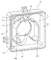
図1において、密閉型ランプ装置100は、照明光源となる放電ランプバーナー11と、椀状に形成され、放電ランプバーナー11の放射光を反射する凹面反射鏡12とを有するランプユニット10と、凹面反射鏡12の前方に装着され、前面に開口部を有する中空ケース体20と、この中空ケース体20の開口部を閉塞し、放電ランプバーナー11の放射光を出射する、レンズまたはガラスや樹脂などの透明材料よりなる前面板30とから概略構成されている。
In FIG. 1, a sealed
前記放電ランプバーナー11は、直流点灯式で、反射体である凹面反射鏡12内に同軸上に収容されて水平に保持されている。つまり、放電ランプバーナー11の支持筒部11aが、凹面反射鏡12の底部中間部に水平方向内方から同軸上に挿通され、電気絶縁セメントにより固着され、外部に突出している。
The
また、放電ランプバーナー11の先端部には、アウターリード11bが軸方向に挿入され、このアウターリード11bの先端にリード線11cが接続され、このリード線11cは、凹面反射鏡12を貫通してその背面側に導出され、点灯回路(図示略す)に接続されている。
An
凹面反射鏡12は、前方が開口され、その中心軸、つまり光軸が放電ランプバーナー11の光軸に一致するように設けられ、放電ランプバーナー11の放射光が凹面反射鏡12の開口側に反射されるようになっている。この凹面反射鏡12は、例えば石英ガラスまたは金属により形成され、その内面に、反射特性に優れたTiO2 −SiO2 などの蒸着膜からなる反射面を有している。
The concave
中空ケース体20は、角形筒状の筒体24と中間部材21とから構成され、外観箱型に形成され、凹面反射鏡12の開口側に同軸上に装着されている。このような中空ケース体20は、凹面反射鏡12の開口幅より幅広に形成されており、筒体24は、その前部中央部に、前面板30が装着される円形の開口部25を有し、後部開口には、角形の中間部材21が固定されている。
The
中間部材21の中央部には、凹面反射鏡12の開口と略整合する略円形の穴部22が形成され、後面には、穴部22の周りを囲繞するように角形の縁部23が、凹面反射鏡12側に突出形成されている。そして、凹面反射鏡12の開口と穴部22とが同軸上に合わせられ、凹面反射鏡12が、縁部23内に固定されることで、凹面反射鏡12と中空ケース体20とによって、放電ランプバーナー11を内包する密閉空間Sが形成されている。
A substantially
また、中空ケース体20は、その内部の熱を外部に効率よく放熱するように、高熱伝導性材料、例えばアルミニウム、銅、マグネシウムからなる。さらに、中空ケース体20の内面には、アルマイト処理または塗装、もしくは何らかの化成表面処理が施され、錆を防止すると同時に熱反射率を低くし、熱輻射率を高くし、放熱効果を高めている。
Further, the
筒体24内には、内部空気の鉛直対流を誘導させる整流板26が形成されている。この整流板26は、筒体24の左右両側壁29の近傍に、間隔を置いて略鉛直方向に延設された一対の帯板26aからなっている。これら一対の帯板26aの上部間には、帯板26aより幅狭の中間板27が架設され、この中間板27の上方の筒体24の上壁に、空気の上昇流を左右方向に誘導する分流板28が略逆三角形状に形成されている。
A rectifying
中空ケース体20内の空気は、放熱ランプバーナー11が点灯し、その輻射熱によって加熱されると、図3に示すように、鉛直対流A1、A2が発生する。鉛直対流A1は、幅狭の中間板27の側端部を通過して、中空ケース体20の上壁に衝突し、帯板26aと側壁29との間に誘導される。
When the heat dissipating
また、鉛直対流A2のように、中空ケース体20の上壁に衝突し、上昇位置より直下に落下しようとする空気流は、中間板28によってその軌道が遮られ、帯板26aと側壁29との間に誘導される。
Further, as in the case of the vertical convection A2, the airflow that collides with the upper wall of the
このように、鉛直対流A1、A2は、整流板26によって中空ケース体20の両側壁29全域に渡って対流されるようになることから、中空ケース体20の内壁のより広い面積に接触して対流するので、中空ケース体20の内壁との間で、効率よく熱交換が行われる。即ち、密閉空間S内の空気熱の大気への放熱効果が高まり、ランプユニット10の冷却が促進される。
Thus, the vertical convections A1 and A2 come into convection across the
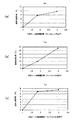
図4は、本実施例の密閉型ランプ装置100において、中空ケース体20の装着により放電ランプバーナー11が臨む密閉空間Sを拡張し、放熱ランプバーナー11の放熱性を確認する実験を行う際の測定箇所を示すもので、図中、Tcfは、放熱ランプバーナー11のフロント部、Tcrは、放熱ランプバーナー11のリヤ部、Tcbは、放熱ランプバーナー11の中間部を示し、これらTcf、TcrおよびTcbの温度変化を熱電対によって個別に測定した。実験の結果、図5に示すように、中空ケース体20の容積の向上に伴って、温度低減効果が、Tcf、TcrおよびTcbの各部位において向上していることが分かった。
FIG. 4 shows a case where the sealed
これは、中空ケース体20が整流板26を有しない場合の実験結果であり、整流板26を有する密閉型ランプ装置100であれば、中空ケース体20の熱交換率の向上によって、温度低減効果をより向上させることができる。
This is an experimental result in the case where the
さらに、このような中空ケース体20は、高熱伝導性材料からなり、内面には、黒色のアルマイト処理または塗装が施されているため、熱反射率が低く、熱輻射率が高くなり、放熱効果の向上が認められ、温度低減効果がより一層向上することになる。
Further, such a
図6に、このような密閉型ランプ装置を備えたプロジェクター200の構成を示す、図6において、プロジェクター200は、外装キャビネット204を有し、この外装キャビネット204内に、光源の密閉型ランプ装置100と、光学系ユニット202とが組み込まれ、密閉型ランプ装置100から出射された光を、光学系ユニット202のライトバルブ203に照射することで得られた映像を、投射レンズ201によってスクリーンに投射して表示するものである。
FIG. 6 shows a configuration of a
また、外装キャビネット204内には、密閉型ランプ装置100および光学系ユニット202を冷却するシロッコファン206と、密閉型ランプ装置100および光学系ユニット202の熱を排出する軸流ファン205と、密閉型ランプ装置100などに電力を供給する電源回路ユニット230と、信号処理回路ユニット208および操作部ユニット209とが組み込まれている。
Further, in the
光学系ユニット202は、フライアイレンズ211、偏光変換素子212、コンデンサーレンズ213、ダイクロイックミラー214、全反射ミラー215、リレーレンズ216、フィールドレンズ217、表示素子である液晶パネル218を備えた3色のライトバルブ203、プリズム219および投射レンズ201を有して構成されている。
The
この光学系ユニット202では、密閉型ランプ装置100で発光された偏りのない白色光が、先ずフライアイレンズ211から偏光変換素子212を透過して直線偏光光に変換されるとともに、コンデンサーレンズ213で集光されて輝度むらのない均一の白色光が形成され、その輝度むらのない白色光がダイクロイックミラー214を経由して3つのライトバルブ203に入射される。
In this
その際、色分離手段であるダイクロイックミラー214によって、白色光が赤色光・緑色光・青色光に分離され、赤色光はリレーレンズ216、全反射ミラー215、リレーレンズ216、全反射ミラー215を介してフィールドレンズ217で集光されて、赤色用のライトバルブ203に入射する。
At that time, white light is separated into red light, green light, and blue light by a
また、緑色光は、ダイクロイックミラー214からフィールドレンズ217で集光されて緑色用のライトバルブ203に入射し、さらに青色光は、ダイクロイックミラー214から全反射ミラー215を介してフィールドレンズ217で集光されて青色用のライトバルブ203に入射する。
The green light is condensed by the
3つのライトバルブ203は、液晶パネル218の入射側と出射側に偏光板221を有して構成され、入射側の偏光板221で各色光の偏光方向が揃えられて液晶パネル218に入射される。液晶パネル218は、各色に対応して印加された映像信号により各色光を変調し、この3つの変調光が出射側の偏光板221を透過して偏光されて映像光となり、プリズム219に入射される。そして、プリズム219では各色の映像光が合成され、この合成された映像光が投射レンズ201によってスクリーンに投射されてフルカラーの映像が映し出されるものである。
The three
シロッコファン206は、ダクト207を介して密閉型ランプ装置100、光学系ユニット202および電源回路ユニット230に送風して冷却を行なう構造となっている。
The
また、投射レンズ201を挟んでその左右両側にシロッコファン206が配置されている。これらシロッコファン206は、その吸気口223、224を投射レンズ201側に向けた状態で配置され、薄型のダクト225、226を介して光学系ユニット202のライトバルブ203付近に送風して冷却を行なうようになっている。
Further,
このように、本実施の形態では、放電ランプバーナー11が占有する密閉容積Sを大きくしたので、密閉型ランプ装置100の放熱性が向上され、これにより、密閉型ランプ装置100の温度が、所定温度範囲内に収めることが可能となり、放電ランプバーナー11の発光効率や寿命を向上することができる。
Thus, in this embodiment, since the sealed volume S occupied by the
さらに、放熱性が向上したので、シロッコファン206や軸流ファン205の送風ファンは、従来よりも少ない風量で効果的な冷却を行なうことができるようになる。従って、送風ファンを、低い回転速度で運転することが可能になり、これによって、送風ファンから発生する騒音を大幅に低減させることができ、消費電力の節約になる。
Furthermore, since the heat dissipation is improved, the
また、このような放熱性の向上は、ランプユニット10に中空ケース体20を取り付けるだけのコンパクトかつ簡単な構造で低コストに実現され、プロジェクター200の大型化やコスト高が避けられる。
Further, such improvement in heat dissipation is realized at a low cost with a compact and simple structure in which the
以上、本発明の実施の形態について詳述したが、本発明は、前記実施の形態記載に限定されるものではなく、本発明の特許請求の範囲に記載されている発明の精神を逸脱しない範囲で、種々の変更ができるものである。 The embodiment of the present invention has been described in detail above, but the present invention is not limited to the above-described embodiment, and the scope does not depart from the spirit of the invention described in the claims of the present invention. Thus, various changes can be made.
例えば、本実施の形態では、中空ケース体20は、凹面反射鏡12の開口幅より幅広に形成されたが、中空ケース体20を凹面反射鏡12の光軸方向に拡張し、放電ランプバーナー11の密閉空間Sを拡大させてもよい。
また、中空ケース体20は、角形に形成されたが、円形状などプロジェクター200への収まりを考慮した適宜の形状に形成してもよい。
For example, in the present embodiment, the
Further, the
10…ランプユニット、11…放電ランプバーナー、12…凹面反射鏡、20…中空ケース体、21…中間部材、22…穴部、25…開口部、23…縁部、24…筒体、26…整流板、26a…帯板、27…中間板、28…分流板、30…前面板、100…密閉型ランプ装置、200…プロジェクター、A1、A2…鉛直対流、S…密閉空間
DESCRIPTION OF
Claims (1)
前方が開口され、光軸が前記放電ランプバーナーの光軸に一致するように設けられ、前記放電ランプバーナーの放射光を開口側に反射する凹面反射鏡と、
前面に開口部を有し、前記凹面反射鏡の開口が臨む中空ケース体と、
前記中空ケース体の開口部を閉塞し、前記放射光を出射する前面板とを備え、
前記中空ケース体は、前記凹面反射鏡の開口幅より幅広であって、前記放電ランプバーナーが占有する密閉容積が大きくなるように形成されるとともに、
前記中空ケース体の内部に、空気の鉛直対流を前記中空ケース体の内壁全域に渡って誘導させる整流板が設けられ、この整流板は、前記中空ケース体の左右両側壁の近傍に間隔を置いて延設された一対の帯板からなるとともに、この一対の帯板の上部間に、前記帯板より幅狭の中間板が架設された
ことを特徴とする密閉型ランプ装置。 A discharge lamp burner,
A concave reflecting mirror that is open at the front, is provided so that its optical axis coincides with the optical axis of the discharge lamp burner, and reflects the emitted light of the discharge lamp burner to the opening side;
A hollow case body having an opening on the front surface and facing the opening of the concave reflecting mirror;
A front plate that closes the opening of the hollow case body and emits the emitted light;
It said hollow casing is a wider than the opening width of the concave reflector, together with the discharge lamp burner is formed so as to enclosed volume occupied is increased,
A rectifying plate for guiding vertical convection of air over the entire inner wall of the hollow case body is provided inside the hollow case body, and the rectifying plates are spaced in the vicinity of the left and right side walls of the hollow case body. A hermetic lamp device comprising a pair of strips extending in an extended manner, and an intermediate plate having a width narrower than that of the strip is provided between the upper portions of the pair of strips .
Priority Applications (2)
| Application Number | Priority Date | Filing Date | Title |
|---|---|---|---|
| JP2006254815A JP4240095B2 (en) | 2006-09-20 | 2006-09-20 | Sealed lamp device and projector |
| US11/901,706 US7866824B2 (en) | 2006-09-20 | 2007-09-18 | Sealed lamp device and projector |
Applications Claiming Priority (1)
| Application Number | Priority Date | Filing Date | Title |
|---|---|---|---|
| JP2006254815A JP4240095B2 (en) | 2006-09-20 | 2006-09-20 | Sealed lamp device and projector |
Publications (2)
| Publication Number | Publication Date |
|---|---|
| JP2008076661A JP2008076661A (en) | 2008-04-03 |
| JP4240095B2 true JP4240095B2 (en) | 2009-03-18 |
Family
ID=39348801
Family Applications (1)
| Application Number | Title | Priority Date | Filing Date |
|---|---|---|---|
| JP2006254815A Expired - Fee Related JP4240095B2 (en) | 2006-09-20 | 2006-09-20 | Sealed lamp device and projector |
Country Status (2)
| Country | Link |
|---|---|
| US (1) | US7866824B2 (en) |
| JP (1) | JP4240095B2 (en) |
Families Citing this family (6)
| Publication number | Priority date | Publication date | Assignee | Title |
|---|---|---|---|---|
| US8313200B2 (en) * | 2010-02-26 | 2012-11-20 | Coretronic Corporation | Light source apparatus and projection device |
| CN103098495B (en) | 2010-09-08 | 2014-09-03 | 松下电器产业株式会社 | Sound reproduction device |
| JP5366228B2 (en) * | 2012-03-30 | 2013-12-11 | Necディスプレイソリューションズ株式会社 | Light source cooling device, projection display device, and light source cooling method |
| JP2017041396A (en) * | 2015-08-21 | 2017-02-23 | セイコーエプソン株式会社 | Discharge lamp, light source device and projector |
| JP6890253B2 (en) * | 2016-11-29 | 2021-06-18 | パナソニックIpマネジメント株式会社 | Light source device and projection type image display device |
| WO2019186408A1 (en) * | 2018-03-27 | 2019-10-03 | Gentex Corporation | Full display mirror with integrated cooling system |
Family Cites Families (13)
| Publication number | Priority date | Publication date | Assignee | Title |
|---|---|---|---|---|
| JPH0550605U (en) * | 1991-12-10 | 1993-07-02 | 市光工業株式会社 | Vehicle parts |
| EP0677766B1 (en) * | 1993-09-30 | 2001-12-12 | Citizen Watch Co. Ltd. | Liquid crystal projector |
| JP3307226B2 (en) * | 1995-11-01 | 2002-07-24 | 松下電器産業株式会社 | Lamp equipment for liquid crystal projection equipment |
| US6398366B1 (en) | 1999-10-15 | 2002-06-04 | Sony Corporation | Image display apparatus of the projection type |
| JP3700571B2 (en) | 1999-10-15 | 2005-09-28 | ソニー株式会社 | Projection display |
| JP2002075014A (en) * | 2000-06-16 | 2002-03-15 | Matsushita Electric Ind Co Ltd | Lamp unit and image projection device |
| JP2004239975A (en) * | 2003-02-03 | 2004-08-26 | Tamron Co Ltd | Lamp holder |
| JP4119350B2 (en) * | 2003-11-14 | 2008-07-16 | フェニックス電機株式会社 | Light source device |
| JP4059251B2 (en) * | 2004-02-27 | 2008-03-12 | セイコーエプソン株式会社 | Light source device and projector |
| JP4196913B2 (en) * | 2004-09-14 | 2008-12-17 | ソニー株式会社 | Projector device |
| JP2006162982A (en) * | 2004-12-07 | 2006-06-22 | Casio Comput Co Ltd | Light source apparatus and projector provided with the same |
| JP3995685B2 (en) * | 2004-12-24 | 2007-10-24 | 三洋電機株式会社 | Projection display device |
| JP2006309096A (en) * | 2005-04-30 | 2006-11-09 | Zero Rabo Kk | Lamp cartridge, lamp cooling device and optical engine unit |
-
2006
- 2006-09-20 JP JP2006254815A patent/JP4240095B2/en not_active Expired - Fee Related
-
2007
- 2007-09-18 US US11/901,706 patent/US7866824B2/en not_active Expired - Fee Related
Also Published As
| Publication number | Publication date |
|---|---|
| JP2008076661A (en) | 2008-04-03 |
| US20080106701A1 (en) | 2008-05-08 |
| US7866824B2 (en) | 2011-01-11 |
Similar Documents
| Publication | Publication Date | Title |
|---|---|---|
| TWI235278B (en) | Light source device and projector | |
| JP6460370B2 (en) | Light source device and image projection device | |
| JP2006267622A (en) | Lamp cooling device and projection type display device | |
| JP4240095B2 (en) | Sealed lamp device and projector | |
| JP6645667B2 (en) | Projection display device | |
| US7237905B2 (en) | Projection type display apparatus and lamp cooling apparatus | |
| JP2017219747A (en) | Fluorescence device, light source device, and image projection device | |
| JP4438626B2 (en) | Light source device and image display device | |
| JP4702625B2 (en) | Electrical equipment with exhaust temperature reduction device | |
| JP2005070216A (en) | Lighting device and projector provided with it | |
| JP2001076505A (en) | Lighting system | |
| JP2007171391A (en) | Projection type display apparatus and cooling method for projection type display apparatus | |
| JP4931563B2 (en) | Rear projector | |
| JP4893933B2 (en) | projector | |
| JP2008016394A (en) | Light source device, lighting device, and projector device | |
| JP6443653B2 (en) | Cooling device and image projection device | |
| JP2500741B2 (en) | LCD projector | |
| JP2702868B2 (en) | LCD projector | |
| JP5003932B2 (en) | Light source device and projector | |
| JP2011203597A (en) | Light source device for projector | |
| JP2678818B2 (en) | LCD projector | |
| JP2010134392A (en) | Air blower for electronic device and electronic device | |
| JP4640639B2 (en) | Light source device and image display device | |
| JP4081988B2 (en) | Display device | |
| JP2006220708A (en) | Projection type display device |
Legal Events
| Date | Code | Title | Description |
|---|---|---|---|
| A977 | Report on retrieval |
Free format text: JAPANESE INTERMEDIATE CODE: A971007 Effective date: 20080919 |
|
| A131 | Notification of reasons for refusal |
Free format text: JAPANESE INTERMEDIATE CODE: A131 Effective date: 20080924 |
|
| A521 | Written amendment |
Free format text: JAPANESE INTERMEDIATE CODE: A523 Effective date: 20081119 |
|
| TRDD | Decision of grant or rejection written | ||
| A01 | Written decision to grant a patent or to grant a registration (utility model) |
Free format text: JAPANESE INTERMEDIATE CODE: A01 Effective date: 20081202 |
|
| A01 | Written decision to grant a patent or to grant a registration (utility model) |
Free format text: JAPANESE INTERMEDIATE CODE: A01 |
|
| A61 | First payment of annual fees (during grant procedure) |
Free format text: JAPANESE INTERMEDIATE CODE: A61 Effective date: 20081215 |
|
| FPAY | Renewal fee payment (event date is renewal date of database) |
Free format text: PAYMENT UNTIL: 20120109 Year of fee payment: 3 |
|
| FPAY | Renewal fee payment (event date is renewal date of database) |
Free format text: PAYMENT UNTIL: 20120109 Year of fee payment: 3 |
|
| LAPS | Cancellation because of no payment of annual fees |