JP4240010B2 - Vehicle stabilizer system - Google Patents
Vehicle stabilizer system Download PDFInfo
- Publication number
- JP4240010B2 JP4240010B2 JP2005177023A JP2005177023A JP4240010B2 JP 4240010 B2 JP4240010 B2 JP 4240010B2 JP 2005177023 A JP2005177023 A JP 2005177023A JP 2005177023 A JP2005177023 A JP 2005177023A JP 4240010 B2 JP4240010 B2 JP 4240010B2
- Authority
- JP
- Japan
- Prior art keywords
- relative rotation
- stabilizer
- pair
- amount
- roll
- Prior art date
- Legal status (The legal status is an assumption and is not a legal conclusion. Google has not performed a legal analysis and makes no representation as to the accuracy of the status listed.)
- Expired - Fee Related
Links
Images


Classifications
-
- B—PERFORMING OPERATIONS; TRANSPORTING
- B60—VEHICLES IN GENERAL
- B60G—VEHICLE SUSPENSION ARRANGEMENTS
- B60G17/00—Resilient suspensions having means for adjusting the spring or vibration-damper characteristics, for regulating the distance between a supporting surface and a sprung part of vehicle or for locking suspension during use to meet varying vehicular or surface conditions, e.g. due to speed or load
- B60G17/015—Resilient suspensions having means for adjusting the spring or vibration-damper characteristics, for regulating the distance between a supporting surface and a sprung part of vehicle or for locking suspension during use to meet varying vehicular or surface conditions, e.g. due to speed or load the regulating means comprising electric or electronic elements
- B60G17/016—Resilient suspensions having means for adjusting the spring or vibration-damper characteristics, for regulating the distance between a supporting surface and a sprung part of vehicle or for locking suspension during use to meet varying vehicular or surface conditions, e.g. due to speed or load the regulating means comprising electric or electronic elements characterised by their responsiveness, when the vehicle is travelling, to specific motion, a specific condition, or driver input
- B60G17/0162—Resilient suspensions having means for adjusting the spring or vibration-damper characteristics, for regulating the distance between a supporting surface and a sprung part of vehicle or for locking suspension during use to meet varying vehicular or surface conditions, e.g. due to speed or load the regulating means comprising electric or electronic elements characterised by their responsiveness, when the vehicle is travelling, to specific motion, a specific condition, or driver input mainly during a motion involving steering operation, e.g. cornering, overtaking
-
- B—PERFORMING OPERATIONS; TRANSPORTING
- B60—VEHICLES IN GENERAL
- B60G—VEHICLE SUSPENSION ARRANGEMENTS
- B60G17/00—Resilient suspensions having means for adjusting the spring or vibration-damper characteristics, for regulating the distance between a supporting surface and a sprung part of vehicle or for locking suspension during use to meet varying vehicular or surface conditions, e.g. due to speed or load
- B60G17/015—Resilient suspensions having means for adjusting the spring or vibration-damper characteristics, for regulating the distance between a supporting surface and a sprung part of vehicle or for locking suspension during use to meet varying vehicular or surface conditions, e.g. due to speed or load the regulating means comprising electric or electronic elements
-
- B—PERFORMING OPERATIONS; TRANSPORTING
- B60—VEHICLES IN GENERAL
- B60G—VEHICLE SUSPENSION ARRANGEMENTS
- B60G21/00—Interconnection systems for two or more resiliently-suspended wheels, e.g. for stabilising a vehicle body with respect to acceleration, deceleration or centrifugal forces
- B60G21/02—Interconnection systems for two or more resiliently-suspended wheels, e.g. for stabilising a vehicle body with respect to acceleration, deceleration or centrifugal forces permanently interconnected
- B60G21/04—Interconnection systems for two or more resiliently-suspended wheels, e.g. for stabilising a vehicle body with respect to acceleration, deceleration or centrifugal forces permanently interconnected mechanically
- B60G21/05—Interconnection systems for two or more resiliently-suspended wheels, e.g. for stabilising a vehicle body with respect to acceleration, deceleration or centrifugal forces permanently interconnected mechanically between wheels on the same axle but on different sides of the vehicle, i.e. the left and right wheel suspensions being interconnected
- B60G21/055—Stabiliser bars
- B60G21/0551—Mounting means therefor
- B60G21/0553—Mounting means therefor adjustable
- B60G21/0555—Mounting means therefor adjustable including an actuator inducing vehicle roll
-
- B—PERFORMING OPERATIONS; TRANSPORTING
- B60—VEHICLES IN GENERAL
- B60G—VEHICLE SUSPENSION ARRANGEMENTS
- B60G2202/00—Indexing codes relating to the type of spring, damper or actuator
- B60G2202/10—Type of spring
- B60G2202/13—Torsion spring
- B60G2202/135—Stabiliser bar and/or tube
-
- B—PERFORMING OPERATIONS; TRANSPORTING
- B60—VEHICLES IN GENERAL
- B60G—VEHICLE SUSPENSION ARRANGEMENTS
- B60G2202/00—Indexing codes relating to the type of spring, damper or actuator
- B60G2202/40—Type of actuator
- B60G2202/42—Electric actuator
-
- B—PERFORMING OPERATIONS; TRANSPORTING
- B60—VEHICLES IN GENERAL
- B60G—VEHICLE SUSPENSION ARRANGEMENTS
- B60G2400/00—Indexing codes relating to detected, measured or calculated conditions or factors
- B60G2400/10—Acceleration; Deceleration
- B60G2400/104—Acceleration; Deceleration lateral or transversal with regard to vehicle
-
- B—PERFORMING OPERATIONS; TRANSPORTING
- B60—VEHICLES IN GENERAL
- B60G—VEHICLE SUSPENSION ARRANGEMENTS
- B60G2400/00—Indexing codes relating to detected, measured or calculated conditions or factors
- B60G2400/20—Speed
- B60G2400/204—Vehicle speed
-
- B—PERFORMING OPERATIONS; TRANSPORTING
- B60—VEHICLES IN GENERAL
- B60G—VEHICLE SUSPENSION ARRANGEMENTS
- B60G2400/00—Indexing codes relating to detected, measured or calculated conditions or factors
- B60G2400/40—Steering conditions
- B60G2400/41—Steering angle
-
- B—PERFORMING OPERATIONS; TRANSPORTING
- B60—VEHICLES IN GENERAL
- B60G—VEHICLE SUSPENSION ARRANGEMENTS
- B60G2400/00—Indexing codes relating to detected, measured or calculated conditions or factors
- B60G2400/90—Other conditions or factors
- B60G2400/98—Stabiliser movement
-
- B—PERFORMING OPERATIONS; TRANSPORTING
- B60—VEHICLES IN GENERAL
- B60G—VEHICLE SUSPENSION ARRANGEMENTS
- B60G2500/00—Indexing codes relating to the regulated action or device
- B60G2500/20—Spring action or springs
-
- B—PERFORMING OPERATIONS; TRANSPORTING
- B60—VEHICLES IN GENERAL
- B60G—VEHICLE SUSPENSION ARRANGEMENTS
- B60G2600/00—Indexing codes relating to particular elements, systems or processes used on suspension systems or suspension control systems
- B60G2600/85—Speed of regulation
-
- B—PERFORMING OPERATIONS; TRANSPORTING
- B60—VEHICLES IN GENERAL
- B60G—VEHICLE SUSPENSION ARRANGEMENTS
- B60G2800/00—Indexing codes relating to the type of movement or to the condition of the vehicle and to the end result to be achieved by the control action
- B60G2800/01—Attitude or posture control
- B60G2800/012—Rolling condition
-
- B—PERFORMING OPERATIONS; TRANSPORTING
- B60—VEHICLES IN GENERAL
- B60G—VEHICLE SUSPENSION ARRANGEMENTS
- B60G2800/00—Indexing codes relating to the type of movement or to the condition of the vehicle and to the end result to be achieved by the control action
- B60G2800/70—Estimating or calculating vehicle parameters or state variables
-
- B—PERFORMING OPERATIONS; TRANSPORTING
- B60—VEHICLES IN GENERAL
- B60G—VEHICLE SUSPENSION ARRANGEMENTS
- B60G2800/00—Indexing codes relating to the type of movement or to the condition of the vehicle and to the end result to be achieved by the control action
- B60G2800/90—System Controller type
- B60G2800/91—Suspension Control
- B60G2800/912—Attitude Control; levelling control
- B60G2800/9122—ARS - Anti-Roll System Control
Landscapes
- Engineering & Computer Science (AREA)
- Mechanical Engineering (AREA)
- Vehicle Body Suspensions (AREA)
Description
本発明は、1対のスタビライザバーによる車体のロールを抑制する効果が可変にされたスタビライザシステムに関する。 The present invention relates to a stabilizer system in which an effect of suppressing a roll of a vehicle body by a pair of stabilizer bars is made variable.
近年、左右1対のスタビライザバーによる車体のロールを抑制する効果であるロール抑制効果が可変にされたスタビライザシステムが検討されている。下記特許文献1には、アクチュエータによって1対のスタビライザバーを相対回転させることにより、ロール抑制効果を変化させるスタビライザシステムが記載されている。
上記特許文献1のスタビライザシステムは、アクチュエータに供給する電流値を制御することにより、1対のスタビライザバーに適切なロール抑制効果を発揮させている。それに対して、基準として設定された相対回転位置からの1対のスタビライザバーの相対回転量が目標となる相対回転量になるように制御することによって、適切なロール抑制効果を発揮させることもできる。その場合には、種々の要因によって、基準として設定された相対回転位置からの相対回転量を適切に取得できない場合がある。例えば、動力停止時の相対回転量を記憶しても、その記憶された相対回転量と車両起動時の相対回転量とが異なっている場合や、左右の車輪の一方の空気圧が低下している等の不具合によって車体の直進時の姿勢がロール方向に傾斜している場合等には、適切な相対回転量を取得することが難しく、適切なロール抑制効果を発揮させることが難しい場合があるという問題がある。
The stabilizer system of the said
以上のような問題は、従来から検討されているスタビライザシステムによって適切なロール抑制効果を発揮させる上で障害となり得る問題の一例であり、スタビライザシステムには種々の観点からの改良の余地がある。すなわち、従来から検討されてきたスタビライザシステムに改良を施すことによって車体のロール方向の姿勢を安定させる効果を向上させる等、実用性を向上させることが可能である。本発明は、そういった実情を鑑みてなされたものであり、より実用的な車両用スタビライザシステムを得ることを課題としてなされたものである。 The problem as described above is an example of a problem that can be an obstacle to exerting an appropriate roll suppressing effect by a stabilizer system that has been studied conventionally. The stabilizer system has room for improvement from various viewpoints. In other words, it is possible to improve the practicality, for example, by improving the stabilizer system that has been studied conventionally and improving the effect of stabilizing the posture of the vehicle body in the roll direction. The present invention has been made in view of such circumstances, and an object of the present invention is to obtain a more practical vehicle stabilizer system.
上記課題を解決するために、本発明の車両用スタビライザシステムは、(a)1対のスタビライザバーの基準相対回転位置からの相対回転量を変化させて、前記1対のスタビライザバーによる車体のロールを抑制する効果であるロール抑制効果を変化させるアクチュエータと、(b)1対のスタビライザバーの基準相対回転位置からの相対回転量が、1対のスタビライザバーに必要に応じたロール抑制効果を発揮させるための目標回転量になるように、アクチュエータを制御するスタビライザ制御装置とを備えるとともに、そのスタビライザ制御装置が、基準相対回転位置を決定する基準相対回転位置決定部を有することを特徴とする。 In order to solve the above-described problems, a vehicle stabilizer system according to the present invention includes: (a) changing a relative rotation amount from a reference relative rotation position of a pair of stabilizer bars to roll a vehicle body by the pair of stabilizer bars; (B) The relative rotation amount from the reference relative rotation position of the pair of stabilizer bars exhibits the roll suppression effect as needed for the pair of stabilizer bars. And a stabilizer control device that controls the actuator so as to achieve a target rotation amount, and the stabilizer control device includes a reference relative rotation position determination unit that determines a reference relative rotation position.
本発明の車両用スタビライザシステムによれば、基準相対回転位置決定部によって基準相対回転位置を適切に決定することができ、1対のスタビライザバーに適切なロール抑制効果を発生させることができる。そして、例えば、基準相対回転位置が不適切であることに起因して、1対のスタビライザバーの捩れ量の過不足が生じ、1対のスタビライザバーに適切なロール抑制効果を発揮させることができなくなることを防止することができる。すなわち、本項に記載の車両用スタビライザシステムによれば、より実用的なスタビライザシステムが得られるのである。なお、本発明の車両用スタビライザシステムの各種態様およびそれらの作用および効果については、以下の、〔発明の態様〕の項において詳しく説明する。 According to the vehicle stabilizer system of the present invention, the reference relative rotation position can be appropriately determined by the reference relative rotation position determination unit, and an appropriate roll suppression effect can be generated in the pair of stabilizer bars. And, for example, due to an inappropriate reference relative rotational position, the pair of stabilizer bars can be excessively or insufficiently twisted, and the pair of stabilizer bars can exhibit an appropriate roll suppressing effect. It can be prevented from disappearing. That is, according to the vehicle stabilizer system described in this section, a more practical stabilizer system can be obtained. Various aspects of the vehicle stabilizer system of the present invention, and their functions and effects will be described in detail in the following [Aspect of the Invention] section.
以下に、本願において特許請求が可能と認識されている発明(以下、「請求可能発明」という場合がある。)の態様をいくつか例示し、それらについて説明する。各態様は請求項と同様に、項に区分し、各項に番号を付し、必要に応じて他の項の番号を引用する形式で記載する。これは、あくまでも請求可能発明の理解を容易にするためであり、請求可能発明を構成する構成要素の組み合わせを、以下の各項に記載されたものに限定する趣旨ではない。つまり、請求可能発明は、各項に付随する記載,実施例の記載等を参酌して解釈されるべきであり、その解釈に従う限りにおいて、各項の態様にさらに他の構成要素を付加した態様も、また、各項の態様から構成要素を削除した態様も、請求可能発明の一態様となり得るのである。 In the following, some aspects of the invention that can be claimed in the present application (hereinafter sometimes referred to as “claimable invention”) will be exemplified and described. As with the claims, each aspect is divided into sections, each section is numbered, and is described in a form that cites the numbers of other sections as necessary. This is for the purpose of facilitating the understanding of the claimable invention, and is not intended to limit the combinations of the constituent elements constituting the claimable invention to those described in the following sections. In other words, the claimable invention should be construed in consideration of the description accompanying each section, the description of the embodiments, etc., and as long as the interpretation is followed, another aspect is added to the form of each section. In addition, an aspect in which constituent elements are deleted from the aspect of each item can be an aspect of the claimable invention.
なお、以下の各項において、(1)項が請求項1に、(2)項,(3)項,および(4)項を合わせたものが請求項2に、(5)項が請求項3に、(6)項が請求項4に、(9)項が請求項5に、(10)項と,(11)項とを合わせたものが請求項6に、(2)項,(3)項,および(12)項を合わせたものが請求項7に、(16)項が請求項8に、(20)項が請求項9に、(21)項と,(22)項とを合わせたものが請求項10に、(25)項が請求項11に、(26)項と,(27)項とを合わせたものが請求項12に、(29)項が請求項13に、(32)項が請求項14に、それぞれ相当する。
In each of the following paragraphs, (1) is claimed in
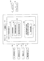
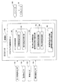
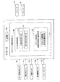
(1)左右の車輪の各々に連結される1対のスタビライザバーと、
駆動力源を有し、その駆動力源の駆動力によって、前記1対のスタビライザバーの相対回転を制御するための基準として定められる相対回転位置である基準相対回転位置からの前記1対のスタビライザバーの相対回転量を変化させて、前記1対のスタビライザバーによる車体のロールを抑制する効果であるロール抑制効果を変化させるアクチュエータと、
前記1対のスタビライザバーの前記基準相対回転位置からの相対回転量が、前記1対のスタビライザバーに必要に応じたロール抑制効果を発揮させるための目標となる前記1対のスタビライザバーの相対回転量である目標回転量になるようにするアクチュエータの制御であるロール抑制制御を行うロール抑制制御部を有するスタビライザ制御装置と
を備えたスタビライザシステムであって、
前記スタビライザ制御装置が、前記基準相対回転位置を決定する基準相対回転位置決定部を有することを特徴とする車両用スタビライザシステム。
(1) a pair of stabilizer bars coupled to each of the left and right wheels;
The pair of stabilizers from a reference relative rotational position, which is a relative rotational position defined as a reference for controlling the relative rotation of the pair of stabilizer bars by the driving force of the driving force source. An actuator that changes a roll suppression effect that is an effect of suppressing a roll of a vehicle body by the pair of stabilizer bars by changing a relative rotation amount of the bar;
The relative rotation amount of the pair of stabilizer bars from the reference relative rotation position is a target for causing the pair of stabilizer bars to exert a roll suppressing effect as necessary. The relative rotation of the pair of stabilizer bars A stabilizer control device having a roll suppression control unit that performs a roll suppression control that is a control of an actuator that achieves a target rotation amount that is a quantity,
The vehicle stabilizer system, wherein the stabilizer control device includes a reference relative rotation position determination unit that determines the reference relative rotation position.
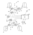
本項に記載の車両用スタビライザシステム(以後、単に「スタビライザシステム」と記載する場合がある)は、1対のスタビライザバーとそれらを相対回転させる駆動装置であるアクチュエータとを備えている。1対のスタビライザバーの各々は、例えば、車体に回転可能に保持された軸状のトーションバー部と、トーションバー部の一端部から車輪に向かって延び出すアーム部を有するものとすることができる。その場合には、例えば、アーム部の先端部を、ロアアーム等の車輪を支持する部材に接続することにより、1対のスタビライザバーの各々を間接的に車輪に連結することができる。また、上記具体例において、トーションバー部が車体に保持され、アーム部が車輪に連結されており、車体と車輪との接近離間により、スタビライザバーをトーションバー部の軸線回りに回転させる作用が生じる構造とすることができる。 The vehicle stabilizer system described in this section (hereinafter may be simply referred to as “stabilizer system”) includes a pair of stabilizer bars and an actuator that is a drive device that relatively rotates them. Each of the pair of stabilizer bars may include, for example, an axial torsion bar portion rotatably held by the vehicle body, and an arm portion extending from one end portion of the torsion bar portion toward the wheel. . In that case, for example, each of the pair of stabilizer bars can be indirectly coupled to the wheel by connecting the tip of the arm portion to a member that supports the wheel, such as a lower arm. Further, in the above specific example, the torsion bar portion is held by the vehicle body, and the arm portion is connected to the wheel, and the action of rotating the stabilizer bar around the axis of the torsion bar portion occurs due to the approach and separation between the vehicle body and the wheel. It can be a structure.
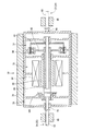
本項に記載のアクチュエータは、例えば、左右に1対のスタビライザバーを接続する接続部を有するものとすることができる。そして、その接続部の各々に接続された1対のスタビライザバーを相対回転駆動し、相対回転を禁止し、相対回転を許容し得るものとすることができる。そのアクチュエータに、例えば、1対のトーションバー部の各々のアーム部と反対側の端部である「接続端部」を接続し、1対のトーションバー部の各々の接続端部にアクチュエータの駆動力が付与されるように構成することができる。以上のように、1対のスタビライザバーの各々が上記トーションバー部と上記アーム部とを有し、1対のトーションバー部の接続端部がアクチュエータに接続されるとともに、アーム部の先端部が車輪に接続されている場合のスタビライザシステムを具体例として、本項に記載のスタビライザシステムについて説明する。 The actuator described in this section can include, for example, a connecting portion that connects a pair of stabilizer bars on the left and right. Then, a pair of stabilizer bars connected to each of the connecting portions can be driven to rotate relative to each other, prohibiting relative rotation, and allowing relative rotation. For example, a “connection end” that is an end opposite to each arm portion of the pair of torsion bar portions is connected to the actuator, and the actuator is driven to each connection end portion of the pair of torsion bar portions. It can be configured to provide force. As described above, each of the pair of stabilizer bars has the torsion bar portion and the arm portion, the connection end portion of the pair of torsion bar portions is connected to the actuator, and the tip end portion of the arm portion is The stabilizer system described in this section will be described by taking a stabilizer system when connected to a wheel as a specific example.
本項に記載のロール抑制制御部は、1対のスタビライザバーのロールを抑制する効果であるロール抑制効果を適切にするために、アクチュエータによって、1対のスタビライザバーを適切に相対回転させる制御を行うものとすることができる。ロール抑制効果は、例えば、ロール量と、1対のスタビライザバーのロールを抑制する力であるロール抑制力(例えば、ロール抑制モーメント等)との関係を変化させることによって、変化させることができる。具体的には、例えば、比較的少ないロール量で比較的大きなロール抑制力を発生させるようにすれば、ロール抑制効果が高くなり、旋回時等におけるロール量を減少させることができる。そのロール抑制力は、通常、1対のスタビライザバーの捩れ量に応じた大きさとなる。なお、1対のスタビライザバーの捩れ量は、上記具体例において、アーム部の先端部とトーションバー部の接続端部との間の捩れ量に応じた量になる。したがって、ロール量が少ない段階で1対のスタビライザバーの捩れ量が増加するように、アクチュエータの駆動力によって1対のスタビライザバーを相対回転させれば、ロール量が少ない段階で比較的大きなロール抑制力が発生し、ロール抑制効果が高まるのである。なお、上述の具体例において、アクチュエータに接続された1対のトーションバー部の各々の接続端部を相対回転させることにより、1対のスタビライザバーを相対回転させることができる。 The roll suppression control unit described in this section performs control to appropriately rotate the pair of stabilizer bars by an actuator in order to appropriately achieve the roll suppression effect that is the effect of suppressing the rolls of the pair of stabilizer bars. Can be done. The roll suppression effect can be changed, for example, by changing the relationship between the roll amount and a roll suppression force (for example, a roll suppression moment) that is a force for suppressing the rolls of the pair of stabilizer bars. Specifically, for example, if a relatively large roll restraining force is generated with a relatively small roll amount, the roll restraining effect is enhanced, and the roll amount during turning can be reduced. The roll restraining force usually has a magnitude corresponding to the amount of twist of the pair of stabilizer bars. Note that the twist amount of the pair of stabilizer bars is an amount corresponding to the twist amount between the tip end portion of the arm portion and the connection end portion of the torsion bar portion in the specific example. Therefore, if the pair of stabilizer bars are rotated relative to each other by the driving force of the actuator so that the twist amount of the pair of stabilizer bars increases when the roll amount is small, a relatively large roll is suppressed when the roll amount is small. Force is generated and the roll suppression effect is enhanced. In the above-described specific example, the pair of stabilizer bars can be relatively rotated by relatively rotating the connection end portions of the pair of torsion bar portions connected to the actuator.
また、本項に記載のロール抑制制御部は、1対のスタビライザバーに適度なロール抑制効果を発揮させるために、1対のスタビライザバーの基準相対回転位置からの相対回転量が目標回転量になるようにしてロールを抑制するものである。基準相対回転位置は、1対のスタビライザバーの相対回転を制御するための基準として定められる相対回転位置である。その基準相対回転位置は、例えば、1対のスタビライザバーの相対回転していない状態の相対回転位置、つまり、1対のスタビライザバーの相対回転位置の中立位置である中立相対回転位置とすることができる。具体的には、例えば、1対のスタビライザバーの各々が捩られていない状態において、左右の車輪の各々と車体との離間距離が等しく、1対のスタビライザバーのアーム部の回転角度が互いに同じ状態とすることができる。また、基準相対回転位置を、例えば、中立相対回転位置以外の相対回転位置とすることもできる。詳細は後述するが、例えば、ロール抑制制御との兼ね合いから、中立相対回転位置以外の相対回転位置を基準相対回転位置としても、適切なロール抑制制御を行うことができるのである。なお、上述の具体例において、アクチュエータに接続された1対のトーションバー部の各々の接続端部の基準相対回転位置からの相対回転量が変化させられて、1対のスタビライザバーの基準相対回転位置からの相対回転量が変化させられる。 Further, the roll suppression control unit described in this section sets the relative rotation amount from the reference relative rotation position of the pair of stabilizer bars to the target rotation amount in order to cause the pair of stabilizer bars to exhibit an appropriate roll suppression effect. In this way, the roll is suppressed. The reference relative rotation position is a relative rotation position determined as a reference for controlling the relative rotation of the pair of stabilizer bars. The reference relative rotation position may be, for example, a relative rotation position in a state where the pair of stabilizer bars are not relatively rotated, that is, a neutral relative rotation position which is a neutral position of the relative rotation position of the pair of stabilizer bars. it can. Specifically, for example, in a state where each of the pair of stabilizer bars is not twisted, the distance between each of the left and right wheels and the vehicle body is equal, and the rotation angles of the arm portions of the pair of stabilizer bars are the same. State. Further, the reference relative rotation position can be set to a relative rotation position other than the neutral relative rotation position, for example. Although details will be described later, for example, appropriate roll suppression control can be performed even if the relative rotation position other than the neutral relative rotation position is set as the reference relative rotation position in consideration of roll suppression control. In the above-described specific example, the relative rotation amount from the reference relative rotation position of each connection end of the pair of torsion bar portions connected to the actuator is changed, so that the reference relative rotation of the pair of stabilizer bars is changed. The amount of relative rotation from the position is changed.
目標回転量は、例えば、車体をロールさせる車両の前後方向の軸線回りの回転方向の力であるロールモーメントに応じた大きさにすることができる。具体的には、例えば、ロールモーメントが大きい場合には、目標回転量を大きくしてロール量当たりの1対のスタビライザバーの捩れ量を増加させて、ロール抑制効果を高めれば、効果的に車体のロールを抑制することができる。しかしながら、基準相対回転位置が不適切であると、例えば、1対のスタビライザバーの捩れ量の過不足により、1対のスタビライザバーに適切なロール抑制効果を発揮させることができなくなる虞がある。基準相対回転位置が不適切なものになる事態は、例えば、車両の起動時に適切な基準相対回転位置が取得できない場合や、スタビライザシステムの作動中に基準相対回転位置がずれた場合等に生ずる。それらの詳細については後述する。 For example, the target rotation amount can be set to a magnitude corresponding to a roll moment that is a force in a rotational direction around an axis in the front-rear direction of the vehicle that rolls the vehicle body. Specifically, for example, when the roll moment is large, the target rotation amount is increased to increase the twist amount of the pair of stabilizer bars per roll amount, and the roll restraining effect is enhanced. The roll of can be suppressed. However, if the reference relative rotational position is inappropriate, for example, the pair of stabilizer bars may not be able to exert an appropriate roll suppressing effect due to excessive or insufficient twisting amount of the pair of stabilizer bars. The situation in which the reference relative rotation position becomes inappropriate occurs, for example, when an appropriate reference relative rotation position cannot be acquired when the vehicle is started, or when the reference relative rotation position is shifted during the operation of the stabilizer system. Details thereof will be described later.
本項に記載のスタビライザ制御装置は、基準相対回転位置決定部によって基準相対回転位置を適切に決定することができ、1対のスタビライザバーに適切なロール抑制効果を発生させることができる。そして、例えば、基準相対回転位置が不適切であることに起因して、1対のスタビライザバーの捩れ量の過不足が生じ、1対のスタビライザバーに適切なロール抑制効果を発揮させることができなくなることを防止することができる。すなわち、本項に記載の車両用スタビライザシステムは、より実用的なスタビライザシステムとされているのである。なお、基準相対回転位置決定部は、例えば、車両の起動後に1回だけ基準相対回転位置の決定を行う態様や、定められた条件が満たされる毎に基準相対回転位置の決定を繰り返し行う態様等とすることができる。 The stabilizer control device described in this section can appropriately determine the reference relative rotation position by the reference relative rotation position determination unit, and can generate an appropriate roll suppression effect on the pair of stabilizer bars. And, for example, due to an inappropriate reference relative rotational position, the pair of stabilizer bars can be excessively or insufficiently twisted, and the pair of stabilizer bars can exhibit an appropriate roll suppressing effect. It can be prevented from disappearing. That is, the vehicle stabilizer system described in this section is a more practical stabilizer system. The reference relative rotation position determination unit, for example, determines the reference relative rotation position only once after starting the vehicle, or repeats the determination of the reference relative rotation position every time a predetermined condition is satisfied. It can be.
アクチュエータの態様は、特に限定されず、例えば、前述の具体例のように、自身に接続された1対のスタビライザバーを相対回転させるものとすることができる。また、駆動力源は、例えば、電動モータとすることができる。1対のスタビライザバーの相対回転位置は、例えば、前述の具体例において、トーションバー部の相対回転位置を取得する相対回転位置センサを設け、その相対回転位置センサによって取得することができる。また、例えば、駆動力源が電動モータである態様において、アクチュエータが、その電動モータの回転位置を取得する回転位置センサを備えている場合には、その回転位置センサの検出信号に基づいて電動モータの回転位置を取得することにより、1対のスタビライザバーの相対回転位置を取得することができる。その回転位置センサは、例えば、ホール素子を用いて磁界の変化を検出するもの、あるいは光学式エンコーダによるもの等とすることができる。 The mode of the actuator is not particularly limited. For example, as in the above-described specific example, a pair of stabilizer bars connected to itself can be relatively rotated. The driving force source can be, for example, an electric motor. The relative rotational position of the pair of stabilizer bars can be obtained by, for example, providing the relative rotational position sensor for obtaining the relative rotational position of the torsion bar portion in the above-described specific example. For example, in an aspect in which the driving force source is an electric motor, when the actuator includes a rotational position sensor that acquires the rotational position of the electric motor, the electric motor is based on the detection signal of the rotational position sensor. By acquiring the rotational position, the relative rotational position of the pair of stabilizer bars can be acquired. The rotational position sensor can be, for example, a sensor that detects a change in a magnetic field using a Hall element, or a sensor that uses an optical encoder.
(2)前記基準相対回転位置決定部が、
前記アクチュエータの駆動力が付与されずに、前記1対のスタビライザバーが前記左右の車輪のうちの一方の車輪と車体との離間距離と、他方の車輪と車体との離間距離との差である離間距離差の変化に応じて相対回転させられる状態である相対回転許容状態において、前記1対のスタビライザバーの、それが相対回転していない状態の相対回転位置である中立相対回転位置からの相対回転量を推定することが可能な物理量である相対回転量推定物理量に基づいて前記基準相対回転位置を決定するように構成された(1)項に記載の車両用スタビライザシステム。
(2) The reference relative rotational position determination unit is
The driving force of the actuator is not applied, and the pair of stabilizer bars is a difference between a separation distance between one of the left and right wheels and the vehicle body and a separation distance between the other wheel and the vehicle body. In the relative rotation allowable state in which the relative rotation is performed in accordance with the change in the separation distance difference, the pair of stabilizer bars are relative to the neutral relative rotational position that is the relative rotational position in the state in which the pair of stabilizer bars are not relatively rotated. The vehicle stabilizer system according to (1), wherein the reference relative rotation position is determined based on a relative rotation amount estimated physical quantity that is a physical quantity capable of estimating a rotation amount.
本項に記載の「相対回転許容状態」は、1対のスタビライザバーにアクチュエータの駆動力が付与されないようにすることによって実現される。具体的には、例えば、アクチュエータが駆動力源としての電動モータを備えている場合には、その電動モータに電力を供給しないようにすることにより、その電動モータが、1対のスタビライザバーの相対回転によって受動的に作動させられる状態にすることができる。また、相対回転許容状態は、例えば、アクチュエータが駆動力源と1対のスタビライザバーとを電磁クラッチ等を介して接続するものである場合には、その電磁クラッチによってアクチュエータの駆動力が1対のスタビライザバーに伝達されない状態にすることにより、実現することができる。 The “relative rotation permissible state” described in this section is realized by preventing the actuator driving force from being applied to the pair of stabilizer bars. Specifically, for example, in the case where the actuator includes an electric motor as a driving force source, the electric motor is prevented from being supplied with electric power by preventing the electric motor from being supplied with electric power. It can be made to be passively actuated by rotation. Further, in the relative rotation permissible state, for example, when the actuator connects the driving force source and the pair of stabilizer bars via an electromagnetic clutch or the like, the driving force of the actuator is set to a pair by the electromagnetic clutch. It can implement | achieve by making it the state which is not transmitted to a stabilizer bar.
相対回転許容状態において、1対のスタビライザバーは概ね離間距離差の変化に応じて相対回転させられる。すなわち、離間距離差が小さい状態において、1対のスタビライザバーの相対回転位置は、中立相対回転位置に近い位置(あるいは、中立相対回転位置)にあると推測することができる。離間距離差は、車体のロールと大きな関連性があり、例えば、ロール量が大きいと離間距離差も大きくなり、旋回時の遠心力が大きいとロール量が大きくなるため離間距離差も大きくなる。一方、車両が水平で平坦な路面に停車している場合には、基本的に、ロール量および離間距離差はほぼ0になる。すなわち、ロール量や遠心力等に基づいて離間距離差を推定でき、また、1対のスタビライザバーの相対回転位置が、中立相対回転位置に近いか否か、さらには、1対のスタビライザバーの相対回転位置から中立相対回転位置までの相対回転量を推定することができるのである。相対回転量推定物理量は、例えば、ロールモーメント,横加速度,ロール量,離間距離差等、およびそれらの大きさを推定し得る物理量とすることができる。 In the relative rotation allowance state, the pair of stabilizer bars are relatively rotated in accordance with the change in the separation distance. That is, in a state where the separation distance difference is small, it can be estimated that the relative rotational position of the pair of stabilizer bars is close to the neutral relative rotational position (or neutral relative rotational position). The separation distance difference is greatly related to the roll of the vehicle body. For example, if the roll amount is large, the separation distance difference is also large, and if the centrifugal force during turning is large, the roll amount is large and the separation distance difference is also large. On the other hand, when the vehicle is stopped on a horizontal and flat road surface, basically, the roll amount and the separation distance are substantially zero. That is, the separation distance difference can be estimated based on the roll amount, the centrifugal force, and the like. Also, whether or not the relative rotational position of the pair of stabilizer bars is close to the neutral relative rotational position. The relative rotation amount from the relative rotation position to the neutral relative rotation position can be estimated. The relative rotation amount estimation physical quantity can be, for example, a roll moment, a lateral acceleration, a roll quantity, a separation distance difference, and the like and a physical quantity capable of estimating the magnitude thereof.
(3)前記基準相対回転位置決定部が、前記相対回転量推定物理量として、(a)車体に加わるロールモーメントの大きさを推定することが可能な物理量であるロールモーメント推定物理量と、(b)前記離間距離差の大きさを推定することが可能な物理量である離間距離差推定物理量との少なくとも一方に基づいて前記基準相対回転位置を決定するように構成された(2)項に記載の車両用スタビライザシステム。 (3) The reference relative rotational position determination unit, as the relative rotational amount estimated physical quantity, (a) a roll moment estimated physical quantity that is a physical quantity capable of estimating the magnitude of the roll moment applied to the vehicle body; and (b) The vehicle according to (2), wherein the reference relative rotational position is determined based on at least one of a separated distance difference estimated physical quantity that is a physical quantity capable of estimating a magnitude of the separated distance difference. Stabilizer system.
ロールモーメント推定物理量は、例えば、車両の構成要素が発生するロールを抑制する回転方向の力であるロール抑制モーメントを考慮せず、旋回時の遠心力等の外力によって車体に作用するロールモーメントである外力ロールモーメントの大きさを推定し得る物理量とすることができる。外力ロールモーメントの大きさは、例えば、横加速度に基づいて推定することができる。すなわち、ロールモーメント推定物理量を、例えば、横加速度,あるいは横加速度を推定し得る物理量とすることができるのである。その横加速度は、例えば、横加速度センサによって検出される実横加速度や、操舵角,ヨーレート,車速等に基づいて推定される推定横加速度とすることができる。さらに、例えば、横加速度推定物理量を、単に、ヨーレート、あるいは操舵角等とすることもできる。 The roll moment estimated physical quantity is, for example, a roll moment that acts on the vehicle body by an external force such as a centrifugal force during turning without considering a roll suppression moment that is a rotational force that suppresses a roll generated by a vehicle component. It can be set as the physical quantity which can estimate the magnitude | size of an external force roll moment. The magnitude of the external force roll moment can be estimated based on the lateral acceleration, for example. That is, the roll moment estimated physical quantity can be set to, for example, a lateral acceleration or a physical quantity that can estimate the lateral acceleration. The lateral acceleration can be, for example, an actual lateral acceleration detected by a lateral acceleration sensor, an estimated lateral acceleration estimated based on a steering angle, a yaw rate, a vehicle speed, or the like. Further, for example, the lateral acceleration estimated physical quantity can be simply a yaw rate or a steering angle.
また、ロールモーメント推定物理量は、例えば、車体のロール加速度,あるいはロール加速度を推定し得る物理量とすることができる。そのロール加速度に基づいて、車体を実際にロールさせる実ロールモーメントを取得することができる。その実ロールモーメントにロール抑制モーメントの大きさを加えることにより、上記外力ロールモーメントを推定することができる。なお、ロール抑制モーメントは、例えば、サスペンション装置,スタビライザ装置等の車両の構成要素が発生するロール抑制モーメントとすることができる。ロール加速度は、例えば、回転方向の加速度を検出するロール加速度センサ,車体の左右に設けられた上下加速度センサ,左右の車輪の各々と車体との離間距離(あるいは、接近・離間量)を取得するストロークセンサ等の検出値に基づいて取得することができる。 Further, the roll moment estimated physical quantity can be, for example, a roll acceleration of the vehicle body or a physical quantity that can estimate the roll acceleration. Based on the roll acceleration, an actual roll moment for actually rolling the vehicle body can be acquired. The external force roll moment can be estimated by adding the magnitude of the roll suppression moment to the actual roll moment. The roll restraining moment can be, for example, a roll restraining moment generated by a vehicle component such as a suspension device or a stabilizer device. As the roll acceleration, for example, a roll acceleration sensor that detects acceleration in the rotation direction, a vertical acceleration sensor provided on the left and right of the vehicle body, and a separation distance (or approach / separation amount) between each of the left and right wheels and the vehicle body are acquired. It can be acquired based on a detection value of a stroke sensor or the like.
離間距離差推定物理量は、例えば、左右の車輪の離間距離差,ロール量,左右の車高差等とすることができる。左右の車輪の各々の離間距離は、例えば、上記ストロークセンサの検出値に基づいて取得することができる。ロール量は、例えば、ロール加速度センサの検出値を2回積分することによって取得することができる。左右の車高差は、例えば、車体の左右に設けられた上下加速度センサの検出値に基づいて取得することができる。 The separation distance difference estimated physical quantity may be, for example, a separation distance difference between left and right wheels, a roll amount, a left and right vehicle height difference, and the like. The separation distance between the left and right wheels can be acquired based on the detection value of the stroke sensor, for example. The roll amount can be obtained by, for example, integrating the detection value of the roll acceleration sensor twice. The difference between the left and right vehicle heights can be acquired, for example, based on the detection value of the vertical acceleration sensor provided on the left and right of the vehicle body.
(4)前記基準相対回転位置決定部が、
前記1対のスタビライザバーが相対回転許容状態である場合に、前記相対回転量推定物理量に基づいて前記基準相対回転位置を決定するように構成された(3)項に記載の車両用スタビライザシステム。
(4) The reference relative rotational position determination unit is
The vehicle stabilizer system according to (3), wherein the reference relative rotation position is determined based on the relative rotation amount estimated physical quantity when the pair of stabilizer bars is in a relative rotation allowable state.
1対のスタビライザバーが相対回転許容状態であれば、相対回転量推定物理量に基づいて1対のスタビライザバーの中立相対回転位置からの相対回転量を推定することができる。そのため、例えば、端的な例を示すと、相対回転量推定物理量が0とみなせる状態では、1対のスタビライザバーの相対回転位置は中立相対回転位置付近の位置(あるいは、中立相対回転位置)になっていると推測することができる。そして、その状態の相対回転位置を基準相対回転位置として決定することや、その状態の相対回転位置から設定された相対回転量へ1対のスタビライザバーを相対回転させた場合の相対回転位置、つまり、上記状態の相対回転位置から設定量だけずれた位置を基準相対回転位置として決定することができる。 If the pair of stabilizer bars is in the relative rotation allowable state, the relative rotation amount from the neutral relative rotation position of the pair of stabilizer bars can be estimated based on the relative rotation amount estimation physical quantity. Therefore, for example, in a simple example, in a state where the estimated physical quantity of relative rotation amount can be regarded as 0, the relative rotation position of the pair of stabilizer bars is a position near the neutral relative rotation position (or neutral relative rotation position). Can be guessed. Then, the relative rotational position in that state is determined as the reference relative rotational position, or the relative rotational position when the pair of stabilizer bars are relatively rotated from the relative rotational position in that state to the set relative rotational amount, that is, A position shifted by a set amount from the relative rotational position in the above state can be determined as the reference relative rotational position.
本項に記載の態様によれば、例えば、相対回転許容状態であれば、車両の走行中であっても基準相対回転位置を決定することができ、1対のスタビライザバーに適切なロール抑制効果を発揮させることができる。本項の相対回転許容状態は、スタビライザ制御装置の制御によって実現されるが、その制御が、例えば、基準相対回転位置を決定する際に相対回転許容状態にする制御であってもよく、設定された条件が満たされた場合に相対回転許容状態にするといった制御であってもよい。 According to the aspect described in this section, for example, in the relative rotation permissible state, the reference relative rotation position can be determined even when the vehicle is traveling, and a roll suppression effect appropriate for a pair of stabilizer bars can be determined. Can be demonstrated. The relative rotation permissible state in this section is realized by the control of the stabilizer control device. However, the control may be, for example, a control for setting the relative rotation permissible state when determining the reference relative rotational position. The control may be such that the relative rotation is permitted when the above conditions are satisfied.
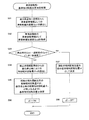
(5)前記ロール抑制制御部が、
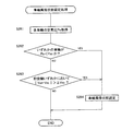
前記相対回転量推定物理量がロール抑制制御の開始時期の基準として設定された制御開始時期設定値を超えた場合にロール抑制制御を行う一方、その制御開始時期設定値を超えない場合に前記1対のスタビライザバーを相対回転許容状態にするものである(4)項に記載の車両用スタビライザシステム。
(5) The roll suppression control unit
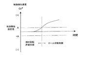
When the estimated physical quantity of relative rotation exceeds a control start time set value set as a reference for the start time of roll suppression control, roll suppression control is performed, and when the relative rotation amount estimated physical quantity does not exceed the control start time set value, The stabilizer system for a vehicle according to item (4), wherein the stabilizer bar is set in a relative rotation permissible state.
本項に記載のロール抑制制御部は、相対回転量推定物理量が制御開始時期設定値を超えない状態ではロール抑制制御を行わず、1対のスタビライザバーが相対回転許容状態になるようにする態様である。そのため、走行中であっても、1対のスタビライザバーが相対回転許容状態にされた場合に基準相対回転位置の決定を行うことができる。本項に記載の態様においては、相対回転量推定物理量が制御開始時期設定値を超えていない状態では、ロール量が比較的少ない,あるいはロールモーメントが比較的小さい状態である場合が多く、ロール抑制制御を行う必要性が低い場合が多い。そのことから、相対回転量推定物理量が制御開始時期設定値を超えていない状態において1対のスタビライザバーを相対回転許容状態にしてもロール抑制効果は損なわれ難いのである。以上のように、本項に記載の態様において、相対回転量推定物理量は、ロール抑制制御を開始する時期を決定する根拠となる制御開始時期決定根拠量として用いられている。また、逆に、相対回転量推定物理量が、1対のスタビライザバーを相対回転許容状態にする時期を決定する根拠となる相対回転許容時期決定根拠量として用いられていると捉えることもできる。 The roll suppression control unit described in this section does not perform roll suppression control in a state where the relative rotation amount estimated physical quantity does not exceed the control start time set value, and causes the pair of stabilizer bars to enter a relative rotation allowable state. It is. Therefore, even when the vehicle is traveling, the reference relative rotation position can be determined when the pair of stabilizer bars are in the relative rotation allowable state. In the mode described in this section, when the relative rotation amount estimated physical quantity does not exceed the control start time set value, the roll amount is relatively small or the roll moment is relatively small, and roll suppression is often caused. There is often a low need for control. Therefore, even if the pair of stabilizer bars are in the relative rotation allowable state in a state where the estimated relative rotation amount physical quantity does not exceed the control start time set value, the roll suppressing effect is hardly impaired. As described above, in the aspect described in this section, the relative rotation amount estimation physical quantity is used as a control start timing determination basis quantity that is a basis for determining the timing of starting the roll suppression control. Conversely, it can also be understood that the relative rotation amount estimation physical quantity is used as a relative rotation permissible time determination basis quantity that is a basis for determining a time when the pair of stabilizer bars are in a relative rotation permissible state.
本項に記載の態様において、例えば、ロール抑制制御を行う必要性が小さい場合、つまり、車両が直進している状態である直進状態とみなせる場合に、1対のスタビライザバーが相対回転許容状態にされるようにすることができる。そのために、例えば、相対回転量推定物理量が0ではないが、車両が直進状態に近い状態である場合の相対回転量推定物理量の値を制御開始時期設定値とすることができる。そのような態様により、ロール抑制制御を行う必要性が小さな直進状態とみなせる状態において、1対のスタビライザバーが相対回転許容状態にされ、基準相対回転位置を決定することができる。 In the aspect described in this section, for example, when the necessity of performing the roll suppression control is small, that is, when the vehicle can be regarded as a straight traveling state in which the vehicle is traveling straight, the pair of stabilizer bars are in a relative rotation allowable state. Can be done. Therefore, for example, the value of the relative rotation amount estimated physical quantity when the relative rotation amount estimated physical quantity is not 0 but the vehicle is in a state of being in a straight traveling state can be set as the control start time setting value. According to such an aspect, in a state where the necessity of performing the roll suppression control is small and can be regarded as a straight traveling state, the pair of stabilizer bars can be allowed to rotate relative to each other, and the reference relative rotation position can be determined.
(6)前記ロール抑制制御部が、目標回転量を決定するための根拠となる目標回転量決定根拠量に基づいて目標回転量を決定する目標回転量決定部を備えるとともに、
その目標回転量決定部が、ロールモーメント推定物理量である前記相対回転量推定物理量を前記目標回転量決定根拠量として用いるものである(5)項に記載の車両用スタビライザシステム。
(6) The roll suppression control unit includes a target rotation amount determination unit that determines a target rotation amount based on a target rotation amount determination basis amount that is a basis for determining the target rotation amount.
The vehicle stabilizer system according to (5), wherein the target rotation amount determination unit uses the relative rotation amount estimation physical quantity, which is a roll moment estimation physical quantity, as the target rotation amount determination basis quantity.
本項に記載のロール抑制制御部において、前述の相対回転量推定物理量がロールモーメント推定物理量であって、そのロールモーメント推定物理量が目標回転量決定根拠量として用いられる。例えば、車体に加わる外力ロールモーメントに応じて目標回転量を決定することにより、1対のスタビライザバーに適切なロール抑制効果を発揮させることができる。そして、本項に記載のロール抑制制御部は、その目標回転量決定根拠量としてのロールモーメント推定物理量を前述の制御開始時期決定根拠量(相対回転許容時期決定根拠量)としても用いるものである。そうすることによって、制御をシンプルなものにできる。 In the roll suppression control unit described in this section, the relative rotation amount estimation physical quantity described above is a roll moment estimation physical quantity, and the roll moment estimation physical quantity is used as a target rotation amount determination basis quantity. For example, by determining the target rotation amount according to the external force roll moment applied to the vehicle body, it is possible to cause the pair of stabilizer bars to exhibit an appropriate roll suppression effect. The roll suppression control unit described in this section uses the roll moment estimated physical quantity as the target rotation amount determination basis amount as the control start timing determination basis amount (relative rotation permissible timing determination basis amount). . By doing so, the control can be simplified.
本項に記載の態様において、車両が直進状態に近い状態である場合のロールモーメント推定物理量の値を制御開始時期設定値とすることができる。そうすることにより、例えば、直進状態におけるロールモーメント推定物理量のわずかな変動やノイズの影響によって、ロール抑制制御が不必要に行われることが防止される。 In the aspect described in this section, the value of the roll moment estimated physical quantity when the vehicle is in a state of being in a straight traveling state can be set as the control start time setting value. By doing so, it is possible to prevent the roll suppression control from being performed unnecessarily due to, for example, slight fluctuations in the roll moment estimated physical quantity in the straight traveling state and the influence of noise.
(7)前記基準相対回転位置決定部が、前記相対回転量推定物理量が増加して前記制御開始時期設定値を超える際に、前記基準相対回転位置を決定するように構成された(5)項または(6)項に記載の車両用スタビライザシステム。 (7) The reference relative rotation position determination unit is configured to determine the reference relative rotation position when the relative rotation amount estimation physical quantity increases and exceeds the control start timing set value. Or the vehicle stabilizer system as described in the item (6).
相対回転量推定物理量が制御開始時期設定値を超えない状態では、ロール抑制制御が行われないため基準相対回転位置を決定する必要性が低い。そのため、相対回転量推定物理量が増加して制御開始時期設定値を超える際に基準相対回転位置を決定すれば、ロール抑制制御の開始時に基準相対回転位置を決定することができ、適切なタイミングで基準相対回転位置を決定することができる。また、以下の4つの項についても同様である。なお、本項の態様が上記(6)項に掛かる場合には、ロールモーメント推定物理量が増加して制御開始時期設定値を超える際に、基準相対回転位置が決定される。また、以下の4つの項についても同様である。 In a state where the relative rotation amount estimation physical quantity does not exceed the control start time set value, roll suppression control is not performed, so that it is less necessary to determine the reference relative rotation position. Therefore, if the reference relative rotation position is determined when the relative rotation amount estimation physical quantity increases and exceeds the control start time set value, the reference relative rotation position can be determined at the start of the roll suppression control, and at an appropriate timing. A reference relative rotational position can be determined. The same applies to the following four terms. When the mode of this section is applied to the above section (6), the reference relative rotational position is determined when the roll moment estimated physical quantity increases and exceeds the control start timing set value. The same applies to the following four terms.
(8)前記基準相対回転位置決定部が、前記相対回転量推定物理量が増加して前記制御開始時期設定値を超える際の前記1対のスタビライザバーの相対回転位置に基づいて、前記基準相対回転位置を決定するように構成された(5)項ないし(7)項のいずれかに記載の車両用スタビライザシステム。 (8) The reference relative rotation position determination unit determines the reference relative rotation based on the relative rotation position of the pair of stabilizer bars when the relative rotation amount estimated physical quantity increases and exceeds the control start time set value. The vehicle stabilizer system according to any one of (5) to (7), wherein the vehicle stabilizer system is configured to determine a position.
本項に記載の態様においては、相対回転量推定物理量が増加して設定値を超える際の1対のスタビライザバーの相対回転位置が取得される。相対回転許容状態において、1対のスタビライザバーがアクチュエータ(例えば、電動モータを含む)等の抵抗に抗して相対回転可能にされている場合には、相対回転量推定物理量が0になっていても、アクチュエータ等の抵抗によって1対のスタビライザバーが中立相対回転位置まで相対回転することができない場合がある。その様な場合に、仮に、相対回転量推定物理量が0になった時点の1対のスタビライザバーの相対回転位置を基準相対回転位置とすると、車体が右にロールした後の基準相対回転位置と、左にロールした後の基準相対回転位置とが異なる場合があり、さらに、その後左右いずれにロールするか予測できないため、適切に基準相対回転位置を決定することが難しい場合がある。それに対して、本項に記載の態様では、相対回転量推定物理量が増加して設定値を超える際には、車体が左右いずれにロールするかが明らかであり、比較的容易に適切に基準相対回転位置を決定することができる。 In the aspect described in this section, the relative rotation position of the pair of stabilizer bars when the relative rotation amount estimation physical quantity increases and exceeds the set value is acquired. In a relative rotation permissible state, when a pair of stabilizer bars is capable of relative rotation against the resistance of an actuator (for example, including an electric motor), the relative rotation amount estimation physical quantity is 0. In some cases, however, the pair of stabilizer bars cannot rotate relative to the neutral relative rotation position due to the resistance of the actuator or the like. In such a case, if the relative rotation position of the pair of stabilizer bars when the estimated relative rotation amount physical quantity becomes zero is set as the reference relative rotation position, the reference relative rotation position after the vehicle body rolls to the right is In some cases, the reference relative rotation position after rolling to the left may be different, and further, since it cannot be predicted whether the roll will roll to the left or right thereafter, it may be difficult to determine the reference relative rotation position appropriately. On the other hand, in the aspect described in this section, when the relative rotation amount estimation physical quantity increases and exceeds the set value, it is clear whether the vehicle body rolls to the left or right, and it is relatively easy to appropriately perform the reference relative The rotational position can be determined.
(9)前記基準相対回転位置決定部が、前記相対回転量推定物理量が増加して前記制御開始時期設定値を超える際の前記1対のスタビライザバーの相対回転位置を、前記基準相対回転位置として決定するように構成された(5)項ないし(8)項のいずれかに記載の車両用スタビライザシステム。 (9) The reference relative rotation position determination unit uses the relative rotation position of the pair of stabilizer bars when the relative rotation amount estimation physical quantity increases and exceeds the control start time set value as the reference relative rotation position. The vehicle stabilizer system according to any one of (5) to (8), configured to be determined.
本項に記載の態様は、上記態様の一具体例である。また、本項に記載の態様は、例えば、車両起動時等、基準相対回転位置が不明である場合に、相対回転量推定物理量が増加して設定値を超える際、つまり、ロール抑制制御が開始される直前の1対のスタビライザバーの相対回転位置を基準相対回転位置とすることができる。また、例えば、車両の動力起動直後に、ロール抑制制御の開始時の1対のスタビライザバーの相対回転位置が中立相対回転位置と大きく異なる位置であった場合でも、とりあえずその相対回転位置を基準相対回転位置とすることにより、制御開始時に1対のスタビライザバーが急激に相対回転させられることによってアクチュエータの作動の円滑さが損なわれないようにすることができる。 The aspect described in this section is a specific example of the above aspect. Further, the aspect described in this section is, for example, when the reference relative rotation position is unknown, such as when the vehicle is started, and when the relative rotation amount estimated physical quantity increases and exceeds the set value, that is, roll suppression control is started. The relative rotational position of the pair of stabilizer bars immediately before being set can be set as the reference relative rotational position. In addition, for example, even if the relative rotational position of the pair of stabilizer bars at the start of the roll suppression control is a position that is significantly different from the neutral relative rotational position immediately after the vehicle power is activated, the relative rotational position is set as a reference relative position for the time being. By setting the rotation position, the smoothness of the operation of the actuator can be prevented from being impaired by a sudden relative rotation of the pair of stabilizer bars at the start of control.
(10)前記基準相対回転位置決定部が、
前記1対のスタビライザバーが、相対回転量推定物理量が増加して前記制御開始時期設定値を超える際の相対回転位置から、中立相対回転位置に近づく向きに設定量相対回転した場合の相対回転位置を、前記基準相対回転位置として決定するように構成された(5)項ないし(9)項のいずれかに記載の車両用スタビライザシステム。
(10) The reference relative rotational position determination unit is
Relative rotational position when the pair of stabilizer bars are rotated relative to the neutral relative rotational position from the relative rotational position when the relative rotational amount estimated physical quantity increases and exceeds the control start time set value. The vehicle stabilizer system according to any one of (5) to (9), wherein the vehicle is determined as the reference relative rotational position.
本項に記載の態様は、ロール抑制制御が開始される際に、1対のスタビライザバーが急激に相対回転させられることによる作動の円滑さが損なわれないようにするために、特に好適な態様である。通常、相対回転量推定物理量が設定値を超える際の目標回転量は、ある程度の大きさの値にされている。つまり、通常、相対回転量推定物理量が設定値を超える際の目標回転量は0でない。その様な場合に、仮に、相対回転量推定物理量が増加して設定値を超える際の1対のスタビライザバーの相対回転位置を基準相対回転位置とすると、ロール抑制制御が開始された直後に1対のスタビライザバーの基準相対回転位置からの相対回転量が目標回転量になるまで急激に相対回転させられることによるショックが発生してしまう場合がある。そこで、本項に記載の態様では、例えば、相対回転量推定物理量が増加して設定値を超える際の1対のスタビライザバーの相対回転位置の基準相対回転位置からの相対回転量が、目標回転量に近い値になるように基準相対回転位置を決定することができる。その場合には、上記相対回転位置から中立相対回転位置に近づく向きに1対のスタビライザバーが設定量相対回転した場合の相対回転位置を、基準相対回転位置として決定する。1対のスタビライザバーを相対回転させる設定量は、例えば、予め試験を行うことによって適切な値とすることができる。 The aspect described in this section is a particularly preferable aspect in order to prevent the smoothness of the operation due to the pair of stabilizer bars being suddenly relatively rotated when the roll suppression control is started. It is. Usually, the target rotation amount when the relative rotation amount estimation physical quantity exceeds the set value is set to a certain value. That is, normally, the target rotation amount when the relative rotation amount estimation physical quantity exceeds the set value is not zero. In such a case, if the relative rotational position of the pair of stabilizer bars when the estimated relative physical quantity of the relative rotational amount increases and exceeds the set value is set as the reference relative rotational position, 1 immediately after the roll suppression control is started. There may be a shock due to a sudden relative rotation until the relative rotation amount from the reference relative rotation position of the pair of stabilizer bars reaches the target rotation amount. Therefore, in the aspect described in this section, for example, the relative rotation amount from the reference relative rotation position of the relative rotation position of the pair of stabilizer bars when the relative rotation amount estimation physical quantity increases and exceeds the set value is the target rotation. The reference relative rotational position can be determined so as to be a value close to the amount. In that case, the relative rotation position when the pair of stabilizer bars rotate relative to the neutral relative rotation position from the relative rotation position by a set amount is determined as the reference relative rotation position. The set amount for relatively rotating the pair of stabilizer bars can be set to an appropriate value by performing a test in advance, for example.
(11)前記基準相対回転位置決定部が、前記1対のスタビライザバーを相対回転させる設定量を、相対回転量推定物理量が増加して前記制御開始時期設定値を超える際の目標回転量と等しくなるように設定するものである(10)項に記載の車両用スタビライザシステム。 (11) The set amount by which the reference relative rotation position determination unit relatively rotates the pair of stabilizer bars is equal to the target rotation amount when the relative rotation amount estimation physical quantity increases and exceeds the control start time setting value. The vehicle stabilizer system according to item (10), which is set to be
本項に記載の態様は、上記の態様において、相対回転量推定物理量が増加して設定値を超える際の1対のスタビライザバーの相対回転位置から、中立相対回転位置に近づく向きに1対のスタビライザバーが目標回転量相対回転した場合の相対回転位置を、基準相対回転位置として決定する態様である。本項に記載の態様は、例えば、ロール抑制制御が開始される直前に、基準相対回転位置を中立相対回転位置に決定する態様であると捉えることができる。 In the aspect described in this section, in the above aspect, a pair of stabilizer bars in a direction approaching the neutral relative rotational position from the relative rotational position of the pair of stabilizer bars when the estimated relative physical quantity of the rotational amount increases and exceeds the set value. In this aspect, the relative rotation position when the stabilizer bar rotates relative to the target rotation amount is determined as the reference relative rotation position. For example, the mode described in this section can be regarded as a mode in which the reference relative rotational position is determined as the neutral relative rotational position immediately before the roll suppression control is started.
(12)前記基準相対回転位置決定部が、
前記1対のスタビライザバーが相対回転許容状態である場合に、相対回転量推定物理量である離間距離差推定物理量に対応する前記1対のスタビライザバーの中立相対回転位置からの相対回転量である離間距離差依拠相対回転量を取得し、その離間距離差依拠相対回転量に基づいて前記基準相対回転位置を決定するように構成された(3)項ないし(5)項のいずれかに記載の車両用スタビライザシステム。
(12) The reference relative rotational position determination unit is
When the pair of stabilizer bars are in a relative rotation permissible state, the separation is a relative rotation amount from the neutral relative rotation position of the pair of stabilizer bars corresponding to the separation distance difference estimated physical amount that is a relative rotation amount estimation physical quantity. The vehicle according to any one of (3) to (5), configured to acquire a distance difference-dependent relative rotation amount and determine the reference relative rotation position based on the separation distance difference-based relative rotation amount Stabilizer system.
本項に記載の態様は、相対回転許容状態において、離間距離差と基準相対回転位置からの相対回転量との間の関係に基づいて、離間距離差推定物理量に対応する離間距離差依拠相対回転量を取得するものである。すなわち、相対回転量推定物理量である離間距離差推定物理量を、文字通り、1対のスタビライザバーの基準相対回転位置からの相対回転量を推定するために利用する態様である。離間距離差依拠相対回転量を取得すれば、例えば、中立相対回転位置が基準相対回転位置とされている場合には、現時点の1対のスタビライザバーの相対回転位置から、1対のスタビライザバーを中立相対回転位置に近づく向きへ離間距離差依拠相対回転量の分相対回転させた場合の相対回転位置を基準相対回転位置として決定することができる。なお、本項に記載の態様において、基準相対回転位置は、中立相対回転位置にされていてもよく、中立相対回転位置以外の相対回転位置にされていてもよい。 The aspect described in this section is based on the relationship between the separation distance difference and the estimated relative physical amount based on the relationship between the separation distance difference and the relative rotation amount from the reference relative rotation position in the relative rotation allowable state. Get the quantity. That is, this is a mode in which the separation distance difference estimated physical quantity, which is a relative rotation quantity estimated physical quantity, is literally used to estimate the relative rotation quantity from the reference relative rotation position of the pair of stabilizer bars. If the relative rotation amount based on the separation distance difference is acquired, for example, when the neutral relative rotation position is set as the reference relative rotation position, the pair of stabilizer bars is changed from the current relative rotation position of the pair of stabilizer bars. It is possible to determine the relative rotation position when the relative rotation is performed by the separation distance difference-based relative rotation amount in the direction approaching the neutral relative rotation position as the reference relative rotation position. In the aspect described in this section, the reference relative rotational position may be a neutral relative rotational position, or may be a relative rotational position other than the neutral relative rotational position.
本項に記載の態様は、相対回転量推定物理量が設定値を超えない状態の前記1対のスタビライザバーの相対回転位置に基づいて、前記基準相対回転位置を決定するように構成することができる。その場合には、例えば、相対回転量推定物理量である離間距離差推定物理量が設定値を超えない場合に、1対のスタビライザバーを相対回転許容状態にするとともに、その離間距離差推定物理量に基づいて離間距離差依拠相対回転量を取得することができる。なお、本項に記載の基準相対回転位置決定部は、例えば、離間距離差依拠相対回転量に依拠して基準相対回転位置を決定する離間距離差依拠相対回転量依拠・基準相対回転位置決定部であると捉えることができる。 The aspect described in this section can be configured to determine the reference relative rotational position based on the relative rotational position of the pair of stabilizer bars in a state where the estimated relative physical amount of the rotational amount does not exceed a set value. . In that case, for example, when the separation distance difference estimated physical quantity that is the relative rotation amount estimation physical quantity does not exceed the set value, the pair of stabilizer bars are set in the relative rotation allowable state, and based on the separation distance difference estimation physical quantity. Thus, the distance difference-based relative rotation amount can be acquired. The reference relative rotation position determination unit described in this section is, for example, a separation distance difference-based relative rotation amount dependency / reference relative rotation position determination unit that determines a reference relative rotation position based on a separation distance difference-based relative rotation amount. It can be understood that.
(13)前記基準相対回転位置決定部が、前記1対のスタビライザバーを中立相対回転位置に近づく向きに前記離間距離差依拠相対回転量相対回転させた場合の相対回転位置を前記基準相対回転位置として決定するように構成された(12)項に記載の車両用スタビライザシステム。 (13) The reference relative rotation position is a relative rotation position when the reference relative rotation position determination unit rotates the pair of stabilizer bars relative to each other in the direction approaching the neutral relative rotation position. The vehicle stabilizer system according to item (12) configured to be determined as:
本項に記載の態様は、基準相対回転位置が中立相対回転位置となるようにする態様である。 The mode described in this section is a mode in which the reference relative rotational position becomes the neutral relative rotational position.
(14)前記ロール抑制制御部が、
ロールモーメント推定物理量である前記目標回転量を決定するための目標回転量決定根拠量に基づいて前記目標回転量を決定する目標回転量決定部を備えるとともに、
前記目標回転量決定根拠量がロール抑制制御の開始時期の基準として設定された制御開始時期設定値を超えた場合にロール抑制制御を行う一方、前記目標回転量決定根拠量がその制御開始時期設定値を超えない場合に前記1対のスタビライザバーを相対回転許容状態にするものであり、
前記基準相対回転位置決定部が、前記目標回転量決定根拠量がその制御開始時期設定値を超えない状態において、前記基準相対回転位置を決定するように構成された(12)項または(13)項に記載の車両用スタビライザシステム。
(14) The roll suppression control unit
A target rotation amount determination unit that determines the target rotation amount based on a target rotation amount determination basis amount for determining the target rotation amount that is a roll moment estimated physical amount;
Roll suppression control is performed when the target rotation amount determination ground amount exceeds a control start time set value set as a reference for the start time of roll suppression control, while the target rotation amount determination ground amount is set to the control start time When the value does not exceed, the pair of stabilizer bars are allowed to rotate relative to each other.
The reference relative rotation position determination unit is configured to determine the reference relative rotation position in a state where the target rotation amount determination ground amount does not exceed the control start time set value (paragraph (12) or (13)) The vehicle stabilizer system according to Item.
本項に記載のロール抑制制御部は、ロールモーメント推定物理量である目標回転量決定根拠量が設定値を超えない場合、例えば、直進時に、1対のスタビライザバーを相対回転許容状態にするものである。そして、本項の基準相対回転位置決定部は、1対のスタビライザバーが相対回転許容状態にされている場合に基準相対回転位置を決定するように構成されている。 The roll suppression control unit described in this section is for setting a pair of stabilizer bars to a relative rotation permissible state when, for example, going straight, when the target rotation amount determination ground amount that is a roll moment estimated physical quantity does not exceed a set value. is there. The reference relative rotation position determination unit of this section is configured to determine the reference relative rotation position when the pair of stabilizer bars are in a relative rotation allowable state.
(15)前記スタビライザ制御装置が、左右の車輪の各々に対応して設けられて左右の車輪の各々と車体との離間距離を検出するストロークセンサの検出値に基づいて前記離間距離差推定物理量を取得するものである(12)項ないし(14)項のいずれかに記載の車両用スタビライザシステム。 (15) The stabilizer control device is configured to calculate the separation distance difference estimated physical quantity based on a detection value of a stroke sensor that is provided corresponding to each of the left and right wheels and detects a separation distance between each of the left and right wheels and the vehicle body. The vehicle stabilizer system according to any one of (12) to (14), which is to be acquired.
離間距離差は、例えば、車体のロール量から推定することができる。しかしながら、路面の凹凸が存在する場合に離間距離差を正確に推定するには、左右の車輪の各々と車体との離間距離を検出するストロークセンサの検出値を用いることが望ましい。 The separation distance difference can be estimated from the roll amount of the vehicle body, for example. However, in order to accurately estimate the separation distance difference when road surface unevenness exists, it is desirable to use the detection value of a stroke sensor that detects the separation distance between each of the left and right wheels and the vehicle body.
(16)前記スタビライザ制御装置が、車両の動力停止時に、停車状態の車両の姿勢である停車姿勢を示す情報である停車姿勢情報,前記基準相対回転位置を特定するための情報である基準位置特定情報を記憶する停止時情報記憶部を備え、
前記基準相対回転位置決定部が、車両起動時の停車姿勢情報と前記停止時情報記憶部に記憶されている動力停止時の停車姿勢情報とが等しい場合に、前記停止時情報記憶部に記憶されている前記基準位置特定情報に基づいて車両起動時の前記基準相対回転位置を決定するように構成された(1)項ないし(15)項のいずれかに記載の車両用スタビライザシステム。
(16) When the power of the vehicle is stopped, the stabilizer control device is stopped posture information that is information indicating a stopped posture that is a posture of the stopped vehicle, and a reference position specifying that is information for specifying the reference relative rotational position. A stop-time information storage unit for storing information is provided,
When the reference relative rotational position determination unit equals the stop posture information at the time of starting the vehicle and the stop posture information at the time of power stop stored in the stop time information storage unit, the reference relative rotation position determination unit is stored in the stop time information storage unit. The vehicle stabilizer system according to any one of (1) to (15), wherein the reference relative rotational position when the vehicle is started is determined based on the reference position specifying information.
通常、車庫や駐車場に停車した車両の停車姿勢が変化する機会は少ない、つまり、停車中に1対のスタビライザバーの基準相対回転位置からの相対回転量が変化する可能性が小さいと考えられるため、多くの場合、基準位置特定情報(例えば、記憶された動力停止時の基準相対回転位置からの相対回転量等)に基づいて動力起動後の基準相対回転位置を適切に決定することができると考えられる。しかしながら、動力停止後に重量物の積み降ろしがなされた場合や、レッカー移動等によって停車場所の地形が変化した場合等には、停車姿勢が変化している可能性が高く、つまり、1対のスタビライザバーの基準相対回転位置からの相対回転量が変化している可能性が高く、その様な事態に適切に対処されなければ誤った基準相対回転位置が決定されて、適切なロール抑制効果を発生させることができなくなる虞がある。 Normally, there is little opportunity for the stopping posture of a vehicle parked in a garage or parking lot to change, that is, the possibility that the relative amount of rotation from the reference relative rotation position of a pair of stabilizer bars during the stop is small. Therefore, in many cases, the reference relative rotation position after power activation can be appropriately determined based on the reference position specifying information (for example, the stored relative rotation amount from the reference relative rotation position when the power is stopped). it is conceivable that. However, when a heavy load is loaded or unloaded after the power is stopped, or when the terrain of the stop location changes due to tow movement, etc., the stop posture is likely to change, that is, a pair of stabilizers. There is a high possibility that the amount of relative rotation from the reference relative rotation position of the bar has changed, and if this situation is not properly dealt with, an incorrect reference relative rotation position is determined and an appropriate roll suppression effect is generated. There is a risk that it will not be possible.
本項に記載の態様は、動力停止時の停車姿勢情報と車両起動時の停車姿勢情報とが等しい場合に、車両の停車姿勢が変化していない、つまり、動力停止時から車両起動時までの間に1対のスタビライザバーの相対回転位置が変化していないと判断し、記憶された動力停止時の基準位置特定情報に基づいて動力起動後の基準相対回転位置を決定する態様である。なお、基準位置特定情報は、例えば、1対のスタビライザバーの基準相対回転位置からの相対回転量や、中立相対回転位置からの相対回転量等とすることができる。そして、具体的には、例えば、車両起動時の前記1対のスタビライザバーの前記基準相対回転位置からの相対回転量が、動力停止時の前記1対のスタビライザバーの前記基準相対回転位置からの相対回転量に等しくなるようにすることにより、基準相対回転位置を適切に決定することができる。 In the aspect described in this section, when the stop posture information at the time of power stop is equal to the stop posture information at the time of vehicle start-up, the vehicle stop posture has not changed, that is, from the time of power stop to the time of vehicle start-up. This is a mode in which it is determined that the relative rotational position of the pair of stabilizer bars has not changed in the meantime, and the reference relative rotational position after power activation is determined based on the stored reference position specifying information when the power is stopped. The reference position specifying information can be, for example, a relative rotation amount from a reference relative rotation position of a pair of stabilizer bars, a relative rotation amount from a neutral relative rotation position, or the like. Specifically, for example, the relative rotation amount from the reference relative rotation position of the pair of stabilizer bars when the vehicle is started is different from the reference relative rotation position of the pair of stabilizer bars when the power is stopped. By making it equal to the relative rotation amount, the reference relative rotation position can be appropriately determined.
本項に記載の態様は、例えば、記憶された動力停止時の相対回転量に基づいて基準相対回転位置を決定するため、例えば、素早く基準相対回転位置を決定することができる。また、本項に記載の態様は、例えば、動力停止後に重量物の積み降ろしやレッカー移動等によって停車姿勢が変化した場合には、動力停止時の停車姿勢情報と車両起動時の停車姿勢情報とが異なることとなり、1対のスタビライザバーの相対回転位置が変化したと判断され、誤った基準相対回転位置が決定されることが防止される。なお、動力停止時の停車姿勢情報と車両起動時の停車姿勢情報とが異なっている場合には、後述するように他の決定手段によって基準相対回転位置を決定することや、仮の基準相対回転位置を決定すること等ができる。なお、本項の基準相対回転位置決定部は、例えば、停車姿勢情報に依拠して基準相対回転位置を決定する態様であると捉えることができる。 In the aspect described in this section, for example, the reference relative rotation position is determined based on the stored relative rotation amount at the time of stopping the power. Therefore, for example, the reference relative rotation position can be quickly determined. In addition, in the aspect described in this section, for example, when the stopping posture is changed by loading / unloading heavy loads or moving tow truck after stopping the power, the stopping posture information when the power is stopped and the stopping posture information when the vehicle is started Therefore, it is determined that the relative rotational position of the pair of stabilizer bars has changed, and an erroneous reference relative rotational position is prevented from being determined. In addition, when the stopping posture information at the time of power stop and the stopping posture information at the time of starting the vehicle are different, the reference relative rotation position is determined by other determining means as described later, or a temporary reference relative rotation is performed. The position can be determined. Note that the reference relative rotation position determination unit of this section can be regarded as a mode of determining the reference relative rotation position based on the stop posture information, for example.
(17)前記スタビライザ制御装置が、停車姿勢情報として、車体のロール量を推定することが可能な物理量であるロール量推定物理量を取得するように構成された(16)項に記載の車両用スタビライザシステム。 (17) The vehicle stabilizer according to (16), wherein the stabilizer control device is configured to acquire a roll amount estimation physical quantity that is a physical quantity capable of estimating the roll amount of the vehicle body as the stop posture information. system.
本項に記載のロール量推定物理量は、例えば、横加速度センサによって検出される実横加速度とすることができる。横加速度センサは、車体がロールした状態において重力加速度の影響による実横加速度を検出するものがあり、そのような横加速度センサによって検出された実横加速度に基づけば、動力停止時と車両起動時とにおいて停車姿勢が変化したか否かを判定することができる。また、ロール量推定物理量は、例えば、左右の車輪の各々と車体との離間距離とすることができる。それら左右の離間距離の差から、ロール量を推定することができる。それら左右の離間距離に基づけば、動力停止時と車両起動時とにおいて停車姿勢が変化したか否かを判定することができる。なお、離間距離は、車体の一部分と車輪(あるいは、車輪を支持する部材)との距離を測定するストロークセンサによって検出することができる。また、ロール量推定物理量は、例えば、左右の車輪の各々に対応する車体の部分の路面からの高さである車高を検出する左右の車高センサによって検出される左右の車高値とすることができる。左右の車高値の差から、ロール量を推定することができる。左右の車高値に基づけば、動力停止時と車両起動時とにおいて停車姿勢が変化したか否かを判定することができる。 The roll amount estimated physical quantity described in this section can be, for example, an actual lateral acceleration detected by a lateral acceleration sensor. Some lateral acceleration sensors detect actual lateral acceleration due to the effect of gravitational acceleration when the vehicle is rolled. Based on the actual lateral acceleration detected by such a lateral acceleration sensor, when the power is stopped and when the vehicle is started It can be determined whether or not the stopping posture has changed. The roll amount estimated physical quantity can be, for example, a separation distance between each of the left and right wheels and the vehicle body. The roll amount can be estimated from the difference between the left and right separation distances. Based on these left and right separation distances, it can be determined whether or not the stopping posture has changed between when the power is stopped and when the vehicle is started. The separation distance can be detected by a stroke sensor that measures the distance between a part of the vehicle body and a wheel (or a member that supports the wheel). Further, the estimated roll amount physical quantity is, for example, the left and right vehicle height values detected by the left and right vehicle height sensors that detect the vehicle height that is the height from the road surface of the part of the vehicle body corresponding to each of the left and right wheels. Can do. The roll amount can be estimated from the difference between the left and right vehicle height values. Based on the left and right vehicle height values, it can be determined whether or not the stopping posture has changed between when the power is stopped and when the vehicle is started.
(18)前記基準相対回転位置決定部が、車両の動力起動直後に前記基準相対回転位置を決定するように構成された(16)項または(17)項に記載の車両用スタビライザシステム。 (18) The vehicle stabilizer system according to (16) or (17), wherein the reference relative rotation position determination unit is configured to determine the reference relative rotation position immediately after power activation of the vehicle.
動力起動直後に基準相対回転位置を決定することにより、走行開始直後から適切なロール抑制効果を発生させることができる。 By determining the reference relative rotational position immediately after power activation, it is possible to generate an appropriate roll suppression effect immediately after the start of traveling.
(19)前記基準相対回転位置決定部が、車両起動時の停車姿勢情報と、前記停止時情報記憶部に記憶された動力停止時の停車姿勢情報とが異なる場合に、前記停止時情報記憶部に記憶された前記1対のスタビライザバーの基準相対回転位置からの相対回転量を用いて前記基準相対回転位置を決定せずに、他の決定手段によって前記基準相対回転位置を決定するように構成された(16)項ないし(18)項のいずれかに記載の車両用スタビライザシステム。 (19) When the reference relative rotational position determination unit is different from the stop posture information at the time of starting the vehicle and the stop posture information at the time of power stop stored in the stop time information storage unit, the stop time information storage unit The reference relative rotation position is determined by other determining means without determining the reference relative rotation position using the relative rotation amount from the reference relative rotation position of the pair of stabilizer bars stored in the memory. The vehicle stabilizer system according to any one of (16) to (18).
本項に記載の態様は、動力停止時から車両起動時の間に停車姿勢が変化した場合に、他の決定手段によって基準相対回転位置を決定するものである。基準相対回転位置を決定する他の決定手段は、特に制限されず、例えば、前述のように、1対のスタビライザバーが相対回転許容状態である場合において、相対回転量推定物理量が制御開始時期設定値を超える際の前記1対のスタビライザバーの相対回転位置に基づいて、前記基準相対回転位置を決定する手段等とすることができる。また、他の決定手段は、例えば、後述のように、車両が直進走行している状態において、設定された時間毎に1対のスタビライザバーの既存の基準相対回転位置からの相対回転量を取得するとともに、その取得された相対回転量の少なくとも一部を平均した値に基づいて前記基準相対回転位置を決定する手段とすることができる。なお、既存の基準相対回転位置は、例えば、一旦適切に決定された基準相対回転位置や、仮に決定された基準相対回転位置とすることができる(他の既存の基準相対回転位置についても同様である)。 In the aspect described in this section, the reference relative rotational position is determined by other determining means when the stopping posture changes between the time when the power is stopped and the time when the vehicle is started. The other determining means for determining the reference relative rotation position is not particularly limited. For example, when the pair of stabilizer bars are in the relative rotation allowable state as described above, the relative rotation amount estimated physical quantity is set to the control start time setting. The reference relative rotational position may be determined based on the relative rotational position of the pair of stabilizer bars when exceeding the value. The other determining means obtains the relative rotation amount from the existing reference relative rotation position of the pair of stabilizer bars for each set time in a state where the vehicle is traveling straight ahead, for example, as will be described later. In addition, the reference relative rotation position can be determined based on a value obtained by averaging at least a part of the acquired relative rotation amount. The existing reference relative rotation position can be, for example, a reference relative rotation position that has been appropriately determined, or a temporarily determined reference relative rotation position (the same applies to other existing reference relative rotation positions). is there).
(20)前記基準相対回転位置決定部が、車両が直進走行している状態である直進状態において、前記1対のスタビライザバーの既存の前記基準相対回転位置からの相対回転量を常時取得するとともに、その取得された相対回転量の変化に基づいて前記基準相対回転位置を決定するように構成された(1)項ないし(6)項のいずれかに記載の車両用スタビライザシステム。 (20) The reference relative rotational position determination unit constantly acquires the relative rotational amount from the existing reference relative rotational position of the pair of stabilizer bars in the straight traveling state in which the vehicle is traveling straight ahead. The vehicle stabilizer system according to any one of (1) to (6), wherein the reference relative rotation position is determined based on the obtained change in the relative rotation amount.
直進状態において、路面の凹凸によって左右の車輪の各々が個別に車体に接近離間して1対のスタビライザバーが相対回転させられる場合がある。そのような場合に、ある程度の長さの時間、例えば、車輪が車体に対して複数回接近離間を繰り返す程度の時間において、1対のスタビライザバーが中立相対回転位置を中立位置として相対回転していると考えられる。そして、本項に記載の態様は、例えば、直進状態において、1対のスタビライザバーの既存の基準相対回転位置からの相対回転量の変化に基づき、例えば、統計処理を行うこと等によって、中立相対回転位置を取得することができるのである。具体的には、例えば、ある程度の長さの時間において取得された相対回転量の平均値を求めることによって、中立相対回転位置を取得することができる。そして、例えば、その中立相対回転位置を基準相対回転位置として決定することや、その中立相対回転位置からいずれかの方向に設定量相対回転した場合の位置を基準相対回転位置として決定することができる。すなわち、本項に記載の基準相対回転位置決定部は、例えば、1対のスタビライザバーの既存の基準相対回転位置からの相対回転量の変化に依拠して基準相対回転位置を決定する態様である。なお、本項に記載の態様においては、例えば、車両が直進走行しているとみなせる状態も直進状態であるとみなすことができる。 In a straight traveling state, the left and right wheels may individually approach and separate from the vehicle body due to the unevenness of the road surface, and the pair of stabilizer bars may be relatively rotated. In such a case, the pair of stabilizer bars rotate relative to each other with the neutral relative rotation position as the neutral position for a certain length of time, for example, the time when the wheel repeats approaching and separating multiple times. It is thought that there is. Then, the mode described in this section is, for example, in a straight traveling state, based on a change in the relative rotation amount from the existing reference relative rotation position of the pair of stabilizer bars, for example, by performing a statistical process, etc. The rotational position can be acquired. Specifically, for example, the neutral relative rotation position can be acquired by obtaining an average value of the relative rotation amounts acquired in a certain length of time. Then, for example, the neutral relative rotation position can be determined as the reference relative rotation position, and the position when the set relative rotation is performed in any direction from the neutral relative rotation position can be determined as the reference relative rotation position. . That is, the reference relative rotation position determination unit described in this section is an aspect that determines the reference relative rotation position based on, for example, a change in the relative rotation amount of the pair of stabilizer bars from the existing reference relative rotation position. . In the aspect described in this section, for example, a state where the vehicle can be regarded as traveling straight ahead can also be regarded as a straight traveling state.
(21)前記ロール抑制制御部が、
車体に加わるロールモーメントの大きさを推定することが可能な物理量であるロールモーメント推定物理量が設定値を超えない状態を直進状態と認識するとともに、
直進状態であると認識した場合に、ロール抑制制御を行わず、前記アクチュエータの駆動力が付与されずに、前記1対のスタビライザバーが前記左右の車輪のうちの一方の車輪と車体との離間距離と、他方の車輪と車体との離間距離との差である離間距離差の変化に応じて相対回転させられる状態である相対回転許容状態にするように構成された(20)項に記載の車両用スタビライザシステム。
(21) The roll suppression control unit
While recognizing that the roll moment estimated physical quantity, which is a physical quantity capable of estimating the magnitude of the roll moment applied to the vehicle body, does not exceed the set value, is a straight traveling state,
When it is recognized that the vehicle is traveling straight, roll restraint control is not performed, and the driving force of the actuator is not applied, and the pair of stabilizer bars are separated from one of the left and right wheels and the vehicle body. (20) The configuration described in (20), which is configured to be in a relative rotation permissible state that is a state in which relative rotation is performed according to a change in a separation distance difference that is a difference between a distance and a separation distance between the other wheel and the vehicle body. Vehicle stabilizer system.
本項に記載の態様では、直進状態において、1対のスタビライザバーが相対回転許容状態にされる。そのため、車体のロールへの影響が比較的小さい路面の凹凸上を走行することに起因して離間距離差が増加した際には、車体に対する左右の車輪の接近離間が1対のスタビライザバーによって妨げられず、良好な乗り心地が保たれる。ロールモーメント推定物理量については、前述のロールモーメント推定物理量と同様であるため説明を省略する。具体的には、例えば、横加速度が0に近い状態や、操舵量がほぼ0で走行している状態を直進状態と認識することもできる。また、本項に記載の設定値は、例えば、前述のロール抑制制御の開始時期の基準として設定された制御開始時期設定値以下の値にすることができる。 In the aspect described in this section, the pair of stabilizer bars are set in the relative rotation allowable state in the straight traveling state. Therefore, when the difference in the separation distance increases due to traveling on the unevenness of the road surface that has a relatively small influence on the roll of the vehicle body, the pair of stabilizer bars prevents the left and right wheels from approaching and separating from each other. The ride comfort is maintained. Since the roll moment estimated physical quantity is the same as the above-described roll moment estimated physical quantity, the description thereof is omitted. Specifically, for example, a state in which the lateral acceleration is close to 0 or a state in which the steering amount is approximately 0 can be recognized as a straight traveling state. Further, the set value described in this section can be set to a value equal to or less than the control start time set value set as a reference for the start time of the roll suppression control described above, for example.
(22)前記基準相対回転位置決定部が、前記既存の基準相対回転位置を基準にして取得された前記1対のスタビライザバーの相対回転量の設定された時間内における変化を記憶して、その記憶された相対回転量の変化のピーク値の平均を取得するとともに、前記1対のスタビライザバーの前記既存の基準相対回転位置からの相対回転量が前記ピーク値の平均と等しくなる相対回転位置を、前記基準相対回転位置として決定するように構成された(20)項または(21)項に記載の車両用スタビライザシステム。 (22) The reference relative rotation position determination unit stores a change within a set time of the relative rotation amount of the pair of stabilizer bars acquired with reference to the existing reference relative rotation position, and The average of the peak values of the stored changes in the relative rotational amount is obtained, and the relative rotational position at which the relative rotational amount from the existing reference relative rotational position of the pair of stabilizer bars is equal to the average of the peak values. The vehicle stabilizer system according to (20) or (21), wherein the vehicle stabilizer system is configured to determine the reference relative rotational position.
本項に記載の態様は、相対回転量の変化のピーク値に着目し、そのピーク値の平均となる相対回転位置を基準相対回転位置として決定する態様である。 In the aspect described in this section, attention is paid to the peak value of the change in the relative rotation amount, and the relative rotation position that is the average of the peak values is determined as the reference relative rotation position.
(23)前記スタビライザ制御装置が、左右の車輪の一方の車輪が他方の車輪よりも車体に接近している状態の相対回転量を正の値とし、前記一方の車輪が前記他方の車輪よりも車体から離間している状態の相対回転量を負の値として取得するものである(1)項ないし(22)項に記載の車両用スタビライザシステム。 (23) The stabilizer control device sets a relative rotation amount in a state in which one of the left and right wheels is closer to the vehicle body than the other wheel as a positive value, and the one wheel is more than the other wheel. The vehicle stabilizer system according to any one of (1) to (22), wherein the relative rotation amount in a state of being separated from the vehicle body is acquired as a negative value.
本項に記載の態様は、1対のスタビライザバーが基準相対回転位置からどちらの向きに相対回転しているかを、相対回転量の正負によって判別する態様である。 The mode described in this section is a mode in which the direction in which the pair of stabilizer bars are rotating relative to the reference relative rotation position is determined by the sign of the relative rotation amount.
(24)前記スタビライザ制御装置が、車両の動力起動後に、前記基準相対回転位置決定部によって前記基準相対回転位置が決定されるまでロール抑制制御を行わず、前記アクチュエータの駆動力が付与されずに前記1対のスタビライザバーの相対回転が前記離間距離差の変化に応じて相対回転させられる状態にするように構成された(1)項ないし(23)項に記載の車両用スタビライザシステム。 (24) The stabilizer control device does not perform roll suppression control until the reference relative rotation position is determined by the reference relative rotation position determination unit after the power of the vehicle is activated, and the driving force of the actuator is not applied. The vehicle stabilizer system according to any one of items (1) to (23), wherein the relative rotation of the pair of stabilizer bars is configured to be relatively rotated in accordance with a change in the separation distance.
本項に記載の態様は、走行開始後しばらくの間は、ロール抑制制御を行う必要性が低いことに着目し、基準相対回転位置が決定されるまでロール抑制制御を行わないようにする態様である。本項に記載の態様によれば、例えば、誤った基準相対回転位置を基準にしてロール抑制制御が行われること等を防止することができる。 The aspect described in this section is an aspect in which the roll suppression control is not performed until the reference relative rotation position is determined, paying attention to the low necessity of performing the roll suppression control for a while after the start of traveling. is there. According to the aspect described in this section, for example, it is possible to prevent the roll suppression control from being performed based on an erroneous reference relative rotational position.
(25)前記基準相対回転位置決定部が、
車両が旋回走行をしている状態である旋回状態において、(a)車体の横加速度を推定することが可能な物理量である横加速度推定物理量と、(b)前記左右の車輪のうちの一方の車輪と車体との離間距離と、他方の車輪と車体との離間距離との差である離間距離差の大きさを推定することが可能な物理量である離間距離差推定物理量とに基づいて、前記1対のスタビライザバーによるロール抑制効果の過不足を取得し、その過不足を減少させるべく前記基準相対回転位置を決定するように構成された(1)項に記載の車両用スタビライザシステム。
(25) The reference relative rotational position determination unit
In a turning state in which the vehicle is turning, (a) a lateral acceleration estimated physical quantity that is a physical quantity capable of estimating the lateral acceleration of the vehicle body, and (b) one of the left and right wheels. Based on the separation distance difference estimated physical quantity that is a physical quantity capable of estimating the magnitude of the separation distance difference that is the difference between the separation distance between the wheel and the vehicle body and the separation distance between the other wheel and the vehicle body, The vehicle stabilizer system according to item (1), configured to acquire an excess or deficiency of a roll suppression effect by a pair of stabilizer bars and to determine the reference relative rotational position so as to reduce the excess or deficiency.
本項に記載の態様は、ロール抑制制御が行われている旋回状態において基準相対回転位置を決定する態様である。旋回状態において、車両に設けられたサスペンション装置やスタビライザシステムがロール量,横加速度等に応じて発生するロール抑制モーメントの理論的な大きさは既知であるため、横加速度推定物理量の大きさから車体のロール量を予測することができる。また、実際のロール量である実ロール量は離間距離差推定物理量に基づいて取得することができる。すなわち、横加速度推定物理量と離間距離差推定物理量とに基づいて、実ロール量が、予測されたロール量よりも比較的少ない状態か、あるいは比較的多い状態かを判断することができ、既存の基準相対回転位置が不適切であることに起因するロール抑制効果の過不足を取得することができるのである。 The mode described in this section is a mode in which the reference relative rotational position is determined in the turning state in which the roll suppression control is performed. Since the theoretical magnitude of the roll restraint moment generated by the suspension system and stabilizer system provided in the vehicle according to the roll amount, lateral acceleration, etc. is known in a turning state, The amount of roll can be predicted. The actual roll amount, which is the actual roll amount, can be acquired based on the separation distance difference estimated physical quantity. That is, based on the lateral acceleration estimated physical quantity and the separation distance difference estimated physical quantity, it is possible to determine whether the actual roll amount is a relatively small state or a relatively large state than the predicted roll amount. It is possible to acquire the excess or deficiency of the roll suppression effect due to the inappropriate reference relative rotation position.
具体的には、例えば、実ロール量が設定されたロール量(例えば、目標ロール量の数分の1程度のロール量、あるいは目標ロール量に無関係に設定された比較的少ないロール量)になった際の、実ロール量の増加速度に基づいてロール抑制効果の過不足を判断することができる。例えば、実ロール量の増加速度が、予め基準となるように横加速度推定物理量に応じて設定された基準増加速度と比較して、基準増加速度よりも設定量以上小さい場合にはロール抑制効果が過剰であり、基準増加速度よりも設定量以上大きい場合にはロール抑制効果が不足していると判断することもできる。 Specifically, for example, the actual roll amount is set to a roll amount (for example, a roll amount that is a fraction of the target roll amount, or a relatively small roll amount set regardless of the target roll amount). It is possible to determine whether the roll suppression effect is excessive or insufficient based on the increase rate of the actual roll amount. For example, when the increase speed of the actual roll amount is smaller than the reference increase speed by a predetermined amount or more compared to the reference increase speed set according to the estimated lateral acceleration physical quantity so as to be the reference in advance, the roll suppressing effect is obtained. If it is excessive and larger than the reference increase speed by a set amount or more, it can be determined that the roll suppressing effect is insufficient.
基準相対回転位置は、既存の基準相対回転位置から1対のスタビライザバーをある程度の相対回転量相対回転させた場合の相対回転位置に決定される。その際に、例えば、1対のスタビライザバーを、比較的小さい相対回転量相対回転させることができる。その場合には、基準相対回転位置を一度決定するだけでは不十分となる可能性もあるが、基準相対回転位置を決定する処理を複数回行うことによって、基準相対回転位置を適切なものとすることができる。なお、横加速度推定物理量は、例えば、横加速度センサによって検出することや、操舵角,ヨーレート,車速等に基づいて推定することができる。さらに、例えば、横加速度推定物理量を、単に、ヨーレート、あるいは操舵角等とすることもできる。また、離間距離差推定物理量は、前述の離間距離差推定物理量と同様であるため、説明を省略する。 The reference relative rotation position is determined as a relative rotation position when a pair of stabilizer bars are relatively rotated by a certain amount of relative rotation from the existing reference relative rotation position. At that time, for example, the pair of stabilizer bars can be relatively rotated by a relatively small relative rotation amount. In such a case, it may be insufficient to determine the reference relative rotation position once, but the reference relative rotation position is made appropriate by performing the process of determining the reference relative rotation position a plurality of times. be able to. The lateral acceleration estimated physical quantity can be detected by, for example, a lateral acceleration sensor, or estimated based on a steering angle, a yaw rate, a vehicle speed, or the like. Further, for example, the lateral acceleration estimated physical quantity can be simply a yaw rate or a steering angle. Further, the separation distance difference estimated physical quantity is the same as the above-described separation distance difference estimated physical quantity, and thus description thereof is omitted.
(26)前記基準相対回転位置決定部が、横加速度推定物理量と離間距離差推定物理量との少なくとも一方に基づいて、車両が一定の旋回を行っている状態である定常旋回状態であることを認識するとともに、前記定常旋回状態において基準相対回転位置を決定するものである(25)項に記載の車両用スタビライザシステム。 (26) The reference relative rotational position determination unit recognizes that the vehicle is in a steady turning state in which the vehicle is making a certain turn based on at least one of the lateral acceleration estimated physical quantity and the separated distance difference estimated physical quantity. In addition, the vehicle stabilizer system according to (25), wherein a reference relative rotational position is determined in the steady turning state.
定常旋回状態においては、車体のロール量がほぼ一定の状態となっており、遠心力の作用によって車体をロールさせるロールモーメントと、車両のサスペンションスプリング等および1対のスタビライザバーが発生するロール抑制モーメントとが釣り合った状態となる。そのため、1対のスタビライザバーによるロール抑制効果の過不足を認識しやすく、適切に基準相対回転位置を決定することができる。 In a steady turning state, the roll amount of the vehicle body is almost constant, and a roll moment that rolls the vehicle body by the action of centrifugal force and a roll suppression moment that is generated by a suspension spring of the vehicle and a pair of stabilizer bars. Is in a balanced state. Therefore, it is easy to recognize the excess or deficiency of the roll suppression effect by the pair of stabilizer bars, and the reference relative rotation position can be appropriately determined.
(27)前記基準相対回転位置決定部が、
前記定常旋回状態において離間距離差推定物理量に基づいて取得される実ロール量と、横加速度推定物理量に応じて設定されたロール量の目標値である目標ロール量とに基づいて、前記1対のスタビライザバーの、それが相対回転していない状態の相対回転位置である中立相対回転位置からの相対回転量の過不足量である過不足相対回転量を取得するとともに、
前記1対のスタビライザバーを既存の前記基準相対回転位置から過不足相対回転量相対回転させた場合の相対回転位置を前記基準相対回転位置として決定することにより、前記1対のスタビライザバーによるロール抑制効果の過不足を減少させるように構成された(26)項に記載の車両用スタビライザシステム。
(27) The reference relative rotational position determination unit
Based on the actual roll amount acquired based on the separation distance difference estimated physical quantity in the steady turning state and the target roll amount that is a target value of the roll amount set according to the lateral acceleration estimated physical quantity, the pair of pairs While acquiring the excess / deficiency relative rotation amount that is the excess / deficiency of the relative rotation amount from the neutral relative rotation position that is the relative rotation position of the stabilizer bar in the state where it is not relatively rotating,
Roll control by the pair of stabilizer bars is determined by determining the relative rotation position when the pair of stabilizer bars is rotated relative to the existing reference relative rotation position as the reference relative rotation position. The vehicle stabilizer system according to item (26), which is configured to reduce the excess or deficiency of the effect.
本項に記載の態様においては、実ロール量と目標ロール量とに基づいて過不足相対回転量が取得される。例えば、実ロール量が目標ロール量よりも大きい場合には、1対のスタビライザバーの捩れ量が不足しているために、1対のスタビライザバーが車体のロール量に応じて発生させるロール抑制力が不足している、つまり、ロール抑制効果が不足していると考えられる。そして、1対のスタビライザバーの捩れ量が不足するのは、1対のスタビライザバーの中立相対回転位置からの相対回転量が不足しているからである。すなわち、既存の前記基準相対回転位置が不適切であることに起因して、相対回転量の過不足が生じているのである。その場合には、スタビライザ制御装置によって認識される相対回転量(すなわち、基準相対回転位置からの相対回転量である)が減少するように基準相対回転位置を決定することによって、1対のスタビライザバーの中立相対回転位置からの相対回転量を増加させることができ、1対のスタビライザバーの捩れ量を適切にすることができる。なお、本項の態様とは異なるが、過不足相対回転量をロール量偏差に基づいて取得することも可能である。また、本項の態様を、実ロール量と、目標ロール量との偏差であるロール量偏差が、そのロール量偏差のしきい値である偏差しきい値を超える場合に、過不足相対回転量を取得し、基準相対回転位置を決定する態様とすることもできる。 In the aspect described in this section, the excess / deficiency relative rotation amount is acquired based on the actual roll amount and the target roll amount. For example, when the actual roll amount is larger than the target roll amount, the pair of stabilizer bars generates a roll restraining force that is generated according to the roll amount of the vehicle body because the twist amount of the pair of stabilizer bars is insufficient. Is insufficient, that is, it is considered that the roll suppressing effect is insufficient. The reason why the twist amount of the pair of stabilizer bars is insufficient is that the relative rotation amount from the neutral relative rotation position of the pair of stabilizer bars is insufficient. That is, the relative rotation amount is excessive or insufficient because the existing reference relative rotation position is inappropriate. In that case, the pair of stabilizer bars is determined by determining the reference relative rotation position so that the relative rotation amount recognized by the stabilizer control device (that is, the relative rotation amount from the reference relative rotation position) is decreased. The relative rotation amount from the neutral relative rotation position can be increased, and the twist amount of the pair of stabilizer bars can be made appropriate. In addition, although different from the aspect of this section, it is also possible to acquire the excess / deficiency relative rotation amount based on the roll amount deviation. In addition, when the roll amount deviation that is the deviation between the actual roll amount and the target roll amount exceeds the deviation threshold that is the threshold value of the roll amount deviation, To obtain a reference relative rotational position.
(28)前記基準相対回転位置決定部が、
(a)定常旋回状態において前記1対のスタビライザバーが発生させるロール抑制力と、車体のロール量が横加速度推定物理量に応じて設定されたロール量の目標値である目標ロール量となる場合の前記1対のスタビライザバーが発生させるロール抑制力との差と、(b)定常旋回状態において前記1対のスタビライザバー以外の車両の構成要素が発生させるロール抑制力と、車体のロール量が前記目標ロール量となる場合の前記構成要素が発生させるロール抑制力との差とに基づいて、前記1対のスタビライザバーの、それが相対回転していない状態の相対回転位置である中立相対回転位置からの相対回転量の過不足量である過不足相対回転量を取得するとともに、
前記1対のスタビライザバーを既存の前記基準相対回転位置から過不足相対回転量相対回転させた場合の相対回転位置を前記基準相対回転位置として決定することにより、前記1対のスタビライザバーによるロール抑制効果の過不足を減少させるように構成された(26)項または(27)項に記載の車両用スタビライザシステム。
(28) The reference relative rotational position determination unit
(a) When the roll restraining force generated by the pair of stabilizer bars in the steady turning state and the roll amount of the vehicle body become a target roll amount that is a target value of the roll amount set according to the estimated lateral acceleration physical quantity. The difference between the roll restraining force generated by the pair of stabilizer bars, (b) the roll restraining force generated by the vehicle components other than the pair of stabilizer bars in the steady turning state, and the roll amount of the vehicle body are Based on the difference from the roll restraining force generated by the component when the target roll amount is reached, the neutral relative rotational position of the pair of stabilizer bars that is a relative rotational position in a state in which the pair of stabilizer bars is not relatively rotated. While obtaining the excess and deficiency relative rotation amount that is the excess and deficiency amount of relative rotation amount from
Roll control by the pair of stabilizer bars is determined by determining the relative rotation position when the pair of stabilizer bars is rotated relative to the existing reference relative rotation position as the reference relative rotation position. The vehicle stabilizer system according to the item (26) or the item (27), which is configured to reduce the excess or deficiency of the effect.
1対のスタビライザバーおよび1対のスタビライザバー以外の車両の構成要素(以後、「他の構成要素」と略記する場合がある)の各々について、定常旋回状態におけるロール抑制力と、車体のロール量が目標ロール量となる場合のロール抑制力との差を求めることにより、車体のロール量が目標ロール量となる場合の1対のスタビライザバーが発生するロール抑制力の過不足量を求めることができる。そのロール抑制力の過不足量から、1対のスタビライザバーの捩れ量の過不足量、つまり、1対のスタビライザバーの過不足相対回転量を取得することができる。なお、ロール量の違いによる1対のスタビライザバーおよびサスペンションスプリング等の1対のスタビライザバー以外の車両の構成要素が発生するロール抑制力の差は、例えば、演算により求めることができる。また、例えば、予め試験測定を行うことによって得られた値をスタビライザ制御装置の記憶部に記憶させておくこともできる。なお、過不足相対回転量を、ロール量偏差に基づいて取得することも可能である。 For each of the vehicle components other than the pair of stabilizer bars and the pair of stabilizer bars (hereinafter sometimes abbreviated as “other components”), the roll restraining force in the steady turning state and the roll amount of the vehicle body By calculating the difference from the roll restraining force when the roll amount becomes the target roll amount, the excess / shortage amount of the roll restraining force generated by the pair of stabilizer bars when the roll amount of the vehicle body becomes the target roll amount can be obtained. it can. From the excess and deficiency of the roll restraining force, the excess and deficiency of the twist amount of the pair of stabilizer bars, that is, the excess and deficiency relative rotation amount of the pair of stabilizer bars can be obtained. The difference in roll restraining force generated by the vehicle components other than the pair of stabilizer bars such as the pair of stabilizer bars and the suspension spring due to the difference in the roll amount can be obtained, for example, by calculation. Further, for example, a value obtained by performing a test measurement in advance can be stored in the storage unit of the stabilizer control device. It is also possible to acquire the excess / deficiency relative rotation amount based on the roll amount deviation.
(29)前記アクチュエータが、駆動力源となるモータを備え、そのモータの回転を前記1対のスタビライザバーに伝達することによってそれらを相対回転させるものであり、
前記スタビライザ制御装置が、前記モータの回転量に基づいて前記1対のスタビライザバーの前記基準相対回転位置からの相対回転量を取得するものであり、
前記基準相対回転位置決定部が、前記モータの回転と前記1対のスタビライザバーの相対回転との間にずれが生じた場合に、そのずれに対応する前記1対のスタビライザバーの相対回転量に応じて既存の前記基準相対回転位置を修正することにより、前記基準相対回転位置を決定するように構成された(1)項ないし(28)項のいずれかに記載の車両用スタビライザシステム。
(29) The actuator includes a motor serving as a driving force source, and transmits the rotation of the motor to the pair of stabilizer bars to relatively rotate them.
The stabilizer control device acquires a relative rotation amount from the reference relative rotation position of the pair of stabilizer bars based on the rotation amount of the motor,
When the reference relative rotation position determination unit generates a deviation between the rotation of the motor and the relative rotation of the pair of stabilizer bars, the reference relative rotation position determination unit sets the relative rotation amount of the pair of stabilizer bars corresponding to the deviation. The vehicle stabilizer system according to any one of (1) to (28), wherein the reference relative rotation position is determined by correcting the existing reference relative rotation position accordingly.
本項に記載のスタビライザ制御装置は、駆動力源たるモータ(例えば、電動モータ)の回転量に基づいて1対のスタビライザバーの相対回転量を取得するものである。通常、制御用のモータには、そのモータの回転位置を検出する回転位置センサが設けられているため、その回転位置センサの検出値に基づいて、モータの制御を行うとともに、1対のスタビライザバーの相対回転量を取得でき、別の回転位置センサを設けるのに比べてコスト的に有利である。 The stabilizer control device described in this section acquires the relative rotation amount of a pair of stabilizer bars based on the rotation amount of a motor (for example, an electric motor) serving as a driving force source. Usually, a control motor is provided with a rotational position sensor that detects the rotational position of the motor. Therefore, the motor is controlled based on the detected value of the rotational position sensor and a pair of stabilizer bars. This is advantageous in terms of cost compared to providing another rotational position sensor.
本項に記載の態様において、例えば、モータと1対のスタビライザバーとを、例えば、減速機構を介して接続することができる。その減速機構によって、モータの駆動力が増幅されて1対のスタビライザバーに伝達される。しかしながら、モータの駆動力を1対のスタビライザバーに伝達する際に、例えば、減速機構が有する歯車と歯車との噛み合いが瞬間的に解消することによって歯飛びが生じた場合には、モータが空回りして余分に回転してしまうこととなる。すなわち、モータの回転と1対のスタビライザバーの相対回転との間にずれが生じる場合があるのである。そのままでは、1対のスタビライザバーの基準相対回転位置からの相対回転量が不適切な値となり、適切なロール抑制制御を行うことが困難になる。また、例えば、モータと1対のスタビライザバーとを、電磁クラッチ等の駆動力伝達状態切換機構を介して連結することができる。その場合には、例えば、電磁クラッチによって、駆動力を伝達する状態(1対のスタビライザバーに駆動力を付与する状態)と、駆動力を伝達しない状態(駆動力を付与しない状態)とを切り換えることができる。しかしながら、駆動力を付与する状態において電磁クラッチが滑った場合には、上述の減速機構の歯飛びが生じた場合と同様に、モータの回転と1対のスタビライザバーの相対回転との間にずれが生じて、適切なロール抑制効果を発揮することが困難になる。 In the aspect described in this section, for example, the motor and the pair of stabilizer bars can be connected via, for example, a speed reduction mechanism. By the reduction mechanism, the driving force of the motor is amplified and transmitted to the pair of stabilizer bars. However, when the driving force of the motor is transmitted to a pair of stabilizer bars, for example, if tooth skipping occurs due to momentary disengagement of the gears of the reduction mechanism, the motor will run idle. And it will rotate extra. That is, there may be a deviation between the rotation of the motor and the relative rotation of the pair of stabilizer bars. As it is, the relative rotation amount from the reference relative rotation position of the pair of stabilizer bars becomes an inappropriate value, and it is difficult to perform appropriate roll suppression control. Further, for example, the motor and the pair of stabilizer bars can be connected via a driving force transmission state switching mechanism such as an electromagnetic clutch. In that case, for example, a state in which the driving force is transmitted (a state in which the driving force is applied to the pair of stabilizer bars) and a state in which the driving force is not transmitted (a state in which the driving force is not applied) are switched by an electromagnetic clutch. be able to. However, when the electromagnetic clutch slips in the state where the driving force is applied, the motor is deviated between the rotation of the motor and the relative rotation of the pair of stabilizer bars, similarly to the case where the gear skipping of the speed reduction mechanism occurs. It becomes difficult to exhibit an appropriate roll suppressing effect.
以上の例のように、モータの回転と1対のスタビライザバーの相対回転との間にずれが生じて、適切なロール抑制制御を発揮することが困難になる場合がある。それに対して、本項に記載の基準相対回転位置決定部によれば、モータの回転と1対のスタビライザバーの相対回転との間にずれが生じた場合に、そのずれを修正するように基準相対回転位置を決定することができ、1対のスタビライザバーに適切なロール抑制制御を発揮させることができるのである。なお、本項の基準相対回転位置決定部は、例えば、モータの回転と1対のスタビライザバーの相対回転との間のずれ、すなわち相対回転量のずれが発生した際に基準相対回転位置を決定する相対回転量ずれ発生時・基準相対回転位置決定部であると捉えることができる。 As in the above example, there may be a difference between the rotation of the motor and the relative rotation of the pair of stabilizer bars, and it may be difficult to exert appropriate roll suppression control. On the other hand, according to the reference relative rotation position determination unit described in this section, when a deviation occurs between the rotation of the motor and the relative rotation of the pair of stabilizer bars, the reference is corrected so as to correct the deviation. The relative rotational position can be determined, and appropriate roll suppression control can be exerted on the pair of stabilizer bars. Note that the reference relative rotation position determination unit in this section determines the reference relative rotation position when, for example, a deviation between the rotation of the motor and the relative rotation of the pair of stabilizer bars, that is, a deviation of the relative rotation amount occurs. It can be understood that this is the reference relative rotation position determination unit when the relative rotation amount deviation occurs.
(30)前記スタビライザ制御装置が、モータの回転量に基づいてモータの回転速度を取得するとともに、そのモータの回転速度が設定回転速度を超えた場合に、モータの回転と前記1対のスタビライザバーの相対回転との間にずれが生じていると判定する(29)項に記載の車両用スタビライザシステム。 (30) The stabilizer control device acquires the rotation speed of the motor based on the rotation amount of the motor, and when the rotation speed of the motor exceeds the set rotation speed, the rotation of the motor and the pair of stabilizer bars The vehicle stabilizer system according to the item (29), in which it is determined that there is a deviation from the relative rotation of the vehicle.
例えば、モータの駆動力によって1対のスタビライザバーを相対回転させる場合には、1対のスタビライザバーが捩られることによって、モータの駆動力に逆らう向きの弾性力が発生するため、例えば、無負荷状態のようにモータの回転速度が極端に大きくなることはない。一方、例えば、減速機構の歯飛び等が生じた場合には、モータの駆動力に逆らう向きの弾性力がモータに伝達されないため、モータの負荷が小さくなり、モータの回転速度が急激に上昇する。すなわち、本項に記載の態様では、モータの回転速度が設定回転速度を超えた場合に、減速機構の歯飛び等が生じたと判定されるのである。なお、本項の態様とは異なるが、歯飛び前のモータの回転速度と歯飛び時のモータの回転速度との相対速度が、設定相対速度値を超えた場合に、モータの回転と前記1対のスタビライザバーの相対回転との間にずれが生じていると判定することもできる。 For example, when a pair of stabilizer bars are rotated relative to each other by the driving force of the motor, the pair of stabilizer bars are twisted to generate an elastic force that opposes the driving force of the motor. The rotation speed of the motor does not become extremely high unlike the state. On the other hand, for example, when tooth skipping of the speed reduction mechanism occurs, the elastic force in the direction opposite to the driving force of the motor is not transmitted to the motor, so the load on the motor is reduced and the rotational speed of the motor increases rapidly. . That is, in the aspect described in this section, when the rotational speed of the motor exceeds the set rotational speed, it is determined that tooth skipping of the speed reduction mechanism has occurred. Although different from the aspect of this section, when the relative speed between the rotational speed of the motor before tooth jump and the motor speed at the time of tooth jump exceeds the set relative speed value, the rotation of the motor It can also be determined that there is a deviation between the relative rotation of the pair of stabilizer bars.
(31)前記アクチュエータが、駆動力源となるモータと、自身に入力された前記モータの回転を減速して出力することによって前記1対のスタビライザバーを相対回転させる減速機構とを備え、
前記ロール抑制制御部が、前記モータの回転量に基づいて前記1対のスタビライザバーの相対回転量を取得するものであり、
前記基準相対回転位置決定部が、前記減速機構の歯飛びによって前記モータの回転と前記1対のスタビライザバーの相対回転との間にずれが生じた場合に、そのずれに対応する前記1対のスタビライザバーの相対回転量に応じて既存の前記基準相対回転位置を修正することにより、前記基準相対回転位置を決定するように構成された(1)項ないし(30)項のいずれかに記載の車両用スタビライザシステム。
(31) The actuator includes a motor serving as a driving force source, and a speed reduction mechanism that relatively rotates the pair of stabilizer bars by decelerating and outputting the rotation of the motor input to the actuator.
The roll suppression control unit acquires a relative rotation amount of the pair of stabilizer bars based on a rotation amount of the motor,
When the reference relative rotation position determination unit causes a deviation between the rotation of the motor and the relative rotation of the pair of stabilizer bars due to tooth skipping of the speed reduction mechanism, the pair of pairs corresponding to the deviation. The reference relative rotation position is determined by correcting the existing reference relative rotation position according to a relative rotation amount of a stabilizer bar, according to any one of (1) to (30), wherein the reference relative rotation position is determined. Vehicle stabilizer system.
本項に記載の態様は、モータと1対のスタビライザバーとが減速機構を介して接続された態様である。そのため、減速機構の歯飛びによって、モータの回転と1対のスタビライザバーの相対回転との間にずれが生じる虞がある。しかし、本項に記載の基準相対回転位置決定部によれば、モータの回転と1対のスタビライザバーの相対回転との間にずれが生じた場合に、そのずれを修正するように基準相対回転位置を決定することができ、1対のスタビライザバーに適切なロール抑制制御を発揮させることができるのである。本項に記載の基準相対回転位置決定部は、例えば、減速機構が歯飛びした際に基準相対回転位置を決定する減速機構歯飛び時・基準相対回転位置決定部であると捉えることができる。なお、本項に記載の態様を、前記スタビライザ制御装置が、モータの回転量に基づいてモータの回転速度を取得するとともに、そのモータの回転速度が設定回転速度を超えた場合に、モータの回転と前記1対のスタビライザバーの相対回転との間にずれが生じていると判定する態様とすることができる。 The mode described in this section is a mode in which a motor and a pair of stabilizer bars are connected via a speed reduction mechanism. Therefore, there is a possibility that a deviation occurs between the rotation of the motor and the relative rotation of the pair of stabilizer bars due to skipping of the speed reduction mechanism. However, according to the reference relative rotation position determination unit described in this section, when a deviation occurs between the rotation of the motor and the relative rotation of the pair of stabilizer bars, the reference relative rotation position is corrected so as to correct the deviation. The position can be determined, and a pair of stabilizer bars can exhibit appropriate roll suppression control. The reference relative rotation position determination unit described in this section can be regarded as a deceleration mechanism tooth jump / reference relative rotation position determination unit that determines a reference relative rotation position when the deceleration mechanism skips teeth. In addition, when the stabilizer control device acquires the rotation speed of the motor based on the rotation amount of the motor and the rotation speed of the motor exceeds the set rotation speed, the mode described in this section is used to rotate the motor. And a relative rotation of the pair of stabilizer bars.
(32)前記基準相対回転位置決定部が、
前記左右の車輪の外径が相互に異なる車輪異径状態において、そのことに起因して生じる一方の車輪と車体との離間距離と他方の車輪と車体との離間距離との差である離間距離差によって前記1対のスタビライザバーが相対回転させられたときのその1対のスタビライザバーの相対回転位置を、前記基準相対回転位置として決定するように構成された(1)項ないし(31)項のいずれかに記載の車両用スタビライザシステム。
(32) The reference relative rotational position determination unit
In the state where the outer diameters of the left and right wheels are different from each other, the separation distance that is the difference between the separation distance between one wheel and the vehicle body and the separation distance between the other wheel and the vehicle body caused by that. Paragraphs (1) to (31) are configured to determine the relative rotational position of the pair of stabilizer bars when the pair of stabilizer bars is relatively rotated by the difference as the reference relative rotational position. The vehicle stabilizer system according to any one of the above.
タイヤのパンク,1輪のタイヤ空気圧の過度の減少,外径の異なるテンパタイヤを装着したとき等の車輪異径状態においては、車体の傾斜が生じるとともに、4つの車輪への車体重量の配分が変化して左右における車輪と車体との離間距離差が生じる。その離間距離差は、相対回転許容状態における1対のスタビライザバーの相対回転位置を変化させてしまう。一方、車輪異径状態では、そのことに起因して車体がロールしており、そのロールを抑制すべく、その状態における横加速度等に基づいて車輪異径状態でない通常状態における基準相対回転位置を基準としたロール抑制制御が実行されれば、車体のロール量は適切なものとはならない。本項に記載の態様は、そのことに考慮した態様であり、本項に記載の態様によれば、車輪異径状態に起因して1対のスタビライザバーの相対回転位置を基準としてロール抑制制御が実行されることで、車輪異径状態であっても、適切なロール抑制制御が実現する。 When the tires are punctured, the tire pressure of one wheel is excessively decreased, or when temper tires with different outer diameters are installed, the vehicle body tilts and the vehicle weight is distributed to the four wheels. The distance between the left and right wheels and the vehicle body changes and changes. The separation distance difference changes the relative rotational position of the pair of stabilizer bars in the relative rotation allowable state. On the other hand, in the wheel different diameter state, the vehicle body rolls due to that, and in order to suppress the roll, the reference relative rotational position in the normal state that is not the wheel different diameter state is determined based on the lateral acceleration in the state. If the roll suppression control based on the reference is executed, the roll amount of the vehicle body is not appropriate. The aspect described in this section is an aspect that takes into account that, and according to the aspect described in this section, the roll suppression control is based on the relative rotational position of the pair of stabilizer bars due to the different wheel diameter state. As a result, the appropriate roll suppression control is realized even in the wheel different diameter state.
なお、本項にいう「車輪異径状態に起因して生じる離間距離差によって相対回転させられたときの相対回転位置」とは、例えば、1対のスタビライザバーが相対回転許容状態にある場合において、車輪異径状態によって引き起こされる離間距離差のみが影響した場合の相対回転位置と考えることができる。また、そのときの相対回転位置は、後に説明するように、相対回転量を検出するセンサ等の検出値に基づく実際値であってもよく、また、パンク等、離間距離差が既知である車輪異径状態においては、予め設定されている相対回転位置を採用することも可能である。 The term “relative rotation position when the wheels are rotated relative to each other due to the difference in the separation distance caused by the different wheel diameter state” in this section refers to, for example, when a pair of stabilizer bars are in a relative rotation allowable state. It can be considered as the relative rotational position when only the separation distance difference caused by the wheel different diameter state is affected. Further, the relative rotation position at that time may be an actual value based on a detection value of a sensor or the like that detects the relative rotation amount, as will be described later, and a wheel whose separation distance difference is known, such as puncture. In the different diameter state, it is possible to adopt a preset relative rotational position.
(33)前記基準相対回転位置決定部が、
水平な平坦路に車両が停車した状態と水平な平坦路を車両が直進している状態との少なくとも一方とみなせる状態であって、かつ、前記アクチュエータの駆動力が付与されずに、前記1対のスタビライザバーが前記離間距離差の変化に応じて相対回転させられる状態である相対回転許容状態であるときの前記1対のスタビライザバーの相対回転位置を取得し、その取得した相対回転位置を前記基準相対回転位置として決定するものである(32)項に記載の車両用スタビライザシステム。
(33) The reference relative rotational position determination unit
The vehicle can be regarded as at least one of a state where the vehicle is stopped on a horizontal flat road and a state where the vehicle is traveling straight on the horizontal flat road, and the driving force of the actuator is not applied, and the pair The relative rotation position of the pair of stabilizer bars when the stabilizer bar is in a relative rotation allowance state in which the stabilizer bar is relatively rotated according to the change in the separation distance, and the acquired relative rotation position is The vehicle stabilizer system according to item (32), which is determined as a reference relative rotational position.
本項に記載の態様は、車輪異径状態において実際に検出された相対回転位置に基づいて基準相対回転位置を決定する態様である。本項の態様によれば、基準相対回転位置の決定の根拠となる相対回転位置を容易に取得することができ、また、正確に基準相対回転位置を決定することが可能である。 The mode described in this section is a mode in which the reference relative rotational position is determined based on the relative rotational position actually detected in the wheel different diameter state. According to the aspect of this section, it is possible to easily acquire the relative rotational position that is the basis for determining the reference relative rotational position, and it is possible to accurately determine the reference relative rotational position.
「水平な平坦路に車両が停車した状態」,「水平な平坦路を車両が直進している状態」は、例えば、運転者の主観に基づく判断によって認定される状態であってもよく、また、車速センサ,操舵角センサ等による検出値を基に、スタビライザ制御装置が判断することで認定される状態であってもよい。また、それらの状態における上記相対回転位置は、例えば、ある時点における相対回転位置であってもよく、それらの状態が継続する場合には、その継続する期間の平均的な相対回転位置等であってもよい。 The “state where the vehicle has stopped on a horizontal flat road” and the “state where the vehicle goes straight on the horizontal flat road” may be, for example, a state which is recognized by judgment based on the subjectivity of the driver. In addition, the stabilizer control device may make a determination based on a detection value obtained by a vehicle speed sensor, a steering angle sensor, or the like. Further, the relative rotational position in those states may be, for example, a relative rotational position at a certain point in time, and when those states continue, they are average relative rotational positions in the continuing period, etc. May be.
(34)前記スタビライザ制御装置が、車輪異径状態であることを認定する車輪異径状態認定部を有し、前記基準相対回転位置決定部が、その車輪異径状態認定部による認定に基づいて前記基準相対回転位置を決定するものである(32)項または(33)項に記載の車両用スタビライザシステム。 (34) The stabilizer control device has a wheel different diameter state recognition unit that recognizes that the wheel is different in diameter state, and the reference relative rotational position determination unit is based on the approval by the wheel different diameter state recognition unit. The vehicle stabilizer system according to (32) or (33), which determines the reference relative rotational position.
本項の記載の態様によれば、自動的に車輪異径状態を検出することが可能であり、また、基準相対回転位置の決定の根拠となる相対回転位置を自動的に取得するように構成すれば、自動的な基準相対回転位置の決定が可能となる。「車輪異径状態認定部」における認定の具体的な態様は、特に限定されるものではないが、例えば、タイヤの空気圧に基づいて認定する態様,直進状態における左右の車輪の回転速度の差に基づいて認定する態様等、種々の態様を採用可能である。 According to the aspect described in this section, it is possible to automatically detect a different wheel diameter state, and to automatically acquire a relative rotational position that is a basis for determining a reference relative rotational position. Then, the automatic reference relative rotation position can be determined. The specific mode of recognition in the “wheel different diameter state recognition unit” is not particularly limited. For example, the mode of recognition based on the tire air pressure, the difference between the rotational speeds of the left and right wheels in the straight traveling state, Various modes such as a mode of recognition based on the above can be adopted.
以下、請求可能発明のいくつかの実施例を、図を参照しつつ詳しく説明する。なお、請求可能発明は、決して下記の実施例に限定されるものではなく、下記実施例の他、前記〔発明の態様〕の項に記載された態様を始めとして、当業者の知識に基づいて種々の変更、改良を施した種々の態様で実施することができる。 Several embodiments of the claimable invention will now be described in detail with reference to the drawings. It should be noted that the claimable invention is by no means limited to the following embodiments, and based on the knowledge of those skilled in the art, including the embodiments described in the above [Aspects of the Invention] section. The present invention can be implemented in various modes with various changes and improvements.
1. 第1実施例(制御開始時・基準相対回転位置決定部).
1.1. スタビライザシステムの全体構成.
図1に、請求可能発明の一実施例である車両用スタビライザシステム10を概念的に示す。本スタビライザシステム10は、車両の前輪側、後輪側の各々に配設された2つのスタビライザ装置14を含んで構成されている。スタビライザ装置14はそれぞれ、両端部において左右の車輪16を保持する車輪保持部材(図2参照)に連結されたスタビライザバー20(前記1対のスタビライザバーが連結されたものに相当する)を備えている。そのスタビライザバー20は、中央部で分割されており、左右1対のスタビライザバー部材(前記1対のスタビライザバーの一種である)、すなわち右スタビライザバー部材22と左スタビライザバー部材24とを含む構成のものとされている。それら1対のスタビライザバー部材22,24がアクチュエータ30を介して相対回転可能に接続されており、大まかに言えば、スタビライザ装置14は、アクチュエータ30が、1対のスタビライザバー部材22,24を相対回転させることによって(図の矢印,点線矢印を参照のこと)、スタビライザバー20によってロールを抑制する効果であるロール抑制効果を変化させて車体のロールを抑制する。
1. First embodiment (control start / reference relative rotation position determination unit).
1.1. Overall structure of the stabilizer system.
FIG. 1 conceptually shows a
図2には、一方のスタビライザ装置14の車幅方向の中央から一方側の車輪16にかけての部分が概略的に示されている。本スタビライザシステム10が装備される車両は、それぞれが4つの車輪16の各々に対して設けられた4つの独立懸架式のサスペンション装置38を含んで構成されている。このサスペンション装置38は、一般によく知られたダブルウィシュボーン式のものであり、一端部が車体に回動可能に連結されるとともに他端部が車輪16に連結された車輪保持部材としてのアッパアーム42およびロアアーム44を備えている。それらアッパアーム42およびロアアーム44は、車輪16と車体との接近離間(相対的な上下動の意味)に伴い、上記一端部(車体側)を中心に回動させられ、上記他端部(車輪側)が車体に対して上下させられる。また、サスペンション装置38は、ショックアブソーバ46と、サスペンションスプリング48(本装置では「エアばね」である)とを備えている。それらショックアブソーバ46およびスプリング48は、それぞれ、それらの一端部が車体側のマウント部に、他端部がロアアーム44に連結されている。このような構造から、サスペンション装置38は、車輪16と車体とを弾性的に相互支持するとともに、それらの接近離間に伴う振動に対する減衰力を発生させる機能を果たすものとなっている。
FIG. 2 schematically shows a portion from the center in the vehicle width direction of one
スタビライザ装置14は、先に説明した1対のスタビライザバー部材である右スタビライザバー部材22と左スタビライザバー部材24とを備える(図2には、右スタビライザバー部材22および左スタビライザバー部材24の一方が示されている)。各スタビライザバー部材22,24は、それぞれ、略車幅方向に延びるトーションバー部60と、トーションバー部60と一体化されてそれと交差して概ね車両前方あるいは後方に延びるアーム部62とに区分することができる。各スタビライザバー部材22,24のトーションバー部60は、アーム部62に近い箇所において、車体の一部であるスタビライザ装置配設部64に固定的に設けられた支持部材66によって回転可能に支持され、互いに同軸に配置されている。それらトーションバー部60の端部(車幅方向における中央側の端部)の間には、上述のアクチュエータ30が配設されており、後に詳しく説明するが、各トーションバー部60の端部は、それぞれ、そのアクチュエータ30に接続されている。一方、アーム部62の端部(トーションバー部60側とは反対側の端部)は、上述のロアアーム44に設けられたスタビライザバー連結部68に、それと相対回転可能に連結されている。
The
アクチュエータ30は、図3に模式的に示すように、駆動力源である電動モータ70と、電動モータ70の回転を減速する減速機72とを含んで構成されている。これら電動モータ70および減速機72は、アクチュエータ30の外殻部材であるハウジング74内に設けられている。ハウジング74は、ハウジング保持部材76によって、回転可能かつ軸方向(略車幅方向)に移動不能に、車体に設けられたスタビライザ装置配設部64に保持されている。図2から解るように、ハウジング74の両端部の各々には、2つの出力軸80,82の各々が延び出すように配設されている。それら出力軸80,82のハウジング74から延び出した側の端部が、それぞれ、各スタビライザバー部材22,24の端部と、セレーション嵌合によって相対回転不能に接続されている。また、図3から解るように、一方の出力軸80は、ハウジング74の端部に固定して接続されおり、また、他方の出力軸82は、ハウジング74内に延び入る状態で配設されるとともに、ハウジング74に対して回転可能かつ軸方向に移動不能に支持されている。その出力軸82のハウジング74内に存在する一方の端部が、後に詳しく説明するように、減速機72に接続され、その出力軸82は、減速機72の出力軸を兼ねるものとなっている。
As schematically shown in FIG. 3, the
電動モータ70は、ハウジング74の周壁の内面に沿って一円周上に固定して配置された複数のステータコイル84と、ハウジング74に回転可能に保持された中空状のモータ軸86と、モータ軸86の外周においてステータコイル84と向きあうようにして一円周上に固定して配設された永久磁石88とを含んで構成されている。電動モータ70は、ステータコイル84がステータとして機能し、永久磁石88がロータとして機能するモータであり、3相のDCブラシレスモータとされている。
The
減速機72は、波動発生器(ウェーブジェネレータ)90,フレキシブルギヤ(フレクスプライン)92およびリングギヤ(サーキュラスプライン)94を備え、ハーモニックギヤ機構(ハーモニックドライブ機構(登録商標),ストレイン・ウェーブ・ギヤリング機構等とも呼ばれる)として構成されている。波動発生器90は、楕円状カムと、それの外周に嵌められたボール・ベアリングとを含んで構成されるものであり、モータ軸86の一端部に固定されている。フレキシブルギヤ92は、周壁部が弾性変形可能なカップ形状をなすものとされており、周壁部の開口側の外周に複数の歯が形成されている。このフレキシブルギヤ92は、先に説明した出力軸82に接続され、それによって支持されている。詳しく言えば、出力軸82は、モータ軸86を貫通しており、それから延び出す端部にフレキシブルギヤ92の底部が固着されることで、フレキシブルギヤ92と出力軸82とが接続されているのである。リングギヤ94は、概してリング状をなして内周に複数(フレキシブルギヤの歯数よりやや多い数、例えば2つ多い数)の歯が形成されたものであり、ハウジング74に固定されている。フレキシブルギヤ92は、その周壁部が波動発生器90に外嵌して楕円状に弾性変形させられ、楕円の長軸方向に位置する2箇所においてリングギヤ94と噛合し、他の箇所では噛合しない状態とされている。波動発生器90が1回転(360度)すると、つまり、電動モータ70のモータ軸86が1回転すると、フレキシブルギヤ92とリングギヤ94とが、それらの歯数の差分だけ相対回転させられる。ハーモニックギヤ機構はその構成が公知のものであることから、本減速機72の詳細な図示は省略し、説明はこの程度の簡単なものに留める。
The
なお、アクチュエータ30には、ハウジング74内に、モータ軸86の回転角度、すなわち、電動モータ70の回転角度を検出するためのモータ回転角センサ100が設けられている。モータ回転角センサ100は、本アクチュエータ30ではエンコーダを主体とするものであり、それによる検出値は、電動モータ70の通電相の切換に利用されるとともに、1対のスタビライザバー部材22,24の相対回転量(相対回転角度)を指標するものとして、言い換えれば、アクチュエータ30の動作量を指標するものとして、アクチュエータ30の制御、つまり、スタビライザ装置14によるロール抑制制御に利用される。
The
アクチュエータ30が備える電動モータ70には、制御電源から電力が供給される。本スタビライザシステム10には、図1に示すように、バッテリ102と、そのバッテリ102に接続された2つのインバータ104とが設けられている。インバータ104は駆動回路として機能するものであり、2つのスタビライザ装置14の各々が有する電動モータ70には、2つのインバータ104の各々から電力が供給される。つまり、バッテリ102と、1つのインバータ104とによって、各電動モータ70の制御電源が構成されているのである。なお、電動モータ70は定電圧駆動され、電動モータ70の出力は、それに供給される電流を変更することによって行われる。ちなみに、供給電流は、インバータ104が、PWM(Pulse Width Modulation)によるパルスオン時間とパルスオフ時間との比(Duty比)を変更することによって行われる。
Electric power is supplied from a control power source to the
本スタビライザシステム10は、図1に示すように、スタビライザ装置14、詳しくは、アクチュエータ30の作動を制御する制御装置であるスタビライザ電子制御ユニット(スタビライザECU)110(以下、単に「ECU110」という場合がある)を備えている。そのECU110は、CPU,ROM,RAM等を備えたコンピュータを主体として構成されており、ECU110には、上記モータ回転角センサ100とともに、操舵量としてのステアリング操作部材の操作量であるステアリングホイールの操作角を検出するための操作角センサ120,車両走行速度(以下、「車速」と略す場合がある)を検出するための車速センサ122,および,車体に実際に発生する横加速度である実横加速度を検出する横加速度センサ124が接続されている。(図1では、それぞれ「θM」,「δ」,「V」,「Gy」と表されている)。また、ECU110は、インバータ104にも接続され、ECU110は、インバータ104を制御することで、アクチュエータ30の作動を制御するものとされている。ECU110のコンピュータが備えるROMには、後に説明するスタビライザ装置制御プログラム等のプログラム、スタビライザ装置14の制御に関する各種のマップ等のデータ等が記憶されている。
As shown in FIG. 1, the
なお、本スタビライザシステム10は、前輪側,後輪側の2つのスタビライザ装置14を備えており、それら2つのスタビライザ装置14は、設定されたロール剛性配分に従ってそれぞれが個別に制御され、その個々の制御下において、それぞれが所定のロール抑制モーメントを発生させることになるが、ここからの説明では、特に断わりのない限り、説明の単純化に配慮して、2つのスタビライザ装置14を同一構成のものとして扱い、また、それらを一元化して扱うこととする。
The
1.2. スタビライザ装置の作動.
本スタビライザ装置14は、基本的に、1対のスタビライザバー部材22,24が同じ向きに回転する場合には、それら1対のスタビライザバー部材22,24の各々の回転を許容するようにされている。上述のように、アクチュエータ30は、ハウジング保持部材76によって、回転可能に保持されており、1対のスタビライザバー部材22,24とともに回転することが可能にされているからである。そのため、例えば、左右の車輪16が路面の隆起を同時に通過するような場合に、スタビライザバー20によって車体に対する車輪16の接近が妨げられないため、路面の隆起を通過する際の振動が、車両のサスペンション装置38によって効果的に吸収される。
1.2. Operation of the stabilizer device.
The
また、本スタビライザ装置14は、ECU110によるアクチュエータ30の制御により、1対のスタビライザバー部材22,24の相対回転を許容し、禁止し、さらには1対のスタビライザバー部材22,24を相対回転させることができる。そのようなアクチュエータ30の制御の違いを考慮しつつ、スタビライザ装置14の作動について以下に概説する。1対のスタビライザバー部材22,24の各々のアーム部62は、その端部がロアアーム44に連結されている。そのため、左右のアーム部62の各々は、左右の車輪16の各々の車体に対する接近・離間に伴い、つまり、左右の車輪16の各々と車体との離間距離の変化に伴いトーションバー部60の軸線回りに回転する。また、左右の車輪16の各々の離間距離が互いに異なると、つまり、左右の離間距離の差である離間距離差が生じると、左右のアーム部62の各々の回転角度も異なることとなり、回転角度差が生じる。その際に、左右のトーションバー部60の相対回転が許容されている場合には、1対のスタビライザバー部材22等は、それぞれ自由に回転することができる。一方、左右のトーションバー部60の相対回転がアクチュエータ30によって禁止されている場合には、離間距離差の増加に伴い左右のアーム部62だけが相対回転させられて、左右のトーションバー部60の各々が離間距離差に応じた量捩られることとなる。この捩りによって生じる力は、左右の各々の車輪16と車体とを接近あるいは離間させてロールを抑制する力であるロール抑制力として作用することになる。
In addition, the
さらに、アクチュエータ30によって、左右のトーションバー部60を、例えば、その捩れ量が増加する向きに相対回転させるとロール量が比較的小さい状態でも比較的大きなロール抑制力を発生させることができ、逆向きに相対回転させるとロール量が比較的大きい状態でも比較的小さなロール抑制力を発生させることができる。そのため、左右のトーションバー部60をアクチュエータ30の駆動力によって相対回転させることによって、ロール量の変化、つまり、離間距離差の変化に依らずに、ロール抑制力の大きさを変化させることができるのである。すなわち、左右のトーションバー部60を相対回転させることによって、1対のスタビライザバー部材22,24を相対回転させて、スタビライザバー20のロールを抑制する効果であるロール抑制効果を変化させることができるのである。
Further, when the left and right
1.3. スタビライザ装置制御.
以下に、スタビライザ装置14によって適切なロール抑制効果を発揮させるためのECU110によるアクチュエータ30の制御であるスタビライザ装置制御について詳細に説明する。ECU110は、スタビライザ装置制御プログラムを短い時間間隔で繰り返し実行することによってアクチュエータ30を制御し、1対のスタビライザバー部材22,24に適切なロール抑制効果を発揮させる。図4にスタビライザ装置制御プログラムのフローチャートを示す。ステップ11(以後、ステップ11を「S11」と略記し、他の符号についても同様とする)において、車速V,ステアリングホイールの操作角δ(中立状態、すなわち、直進操作状態を0とした場合において、その状態からの角度偏差)が、それぞれ車速センサ122,操作角センサ120の検出値に基づいて取得される。また、本実施例において、ロール抑制制御時に1対のスタビライザバー部材22,24の目標回転量を決定するための目標回転量決定根拠量として、ロールモーメント推定物理量たる制御横加速度Gy*が取得される。その制御横加速度Gy*は、本実施例において、操作角δと車速Vとに基づいて推定されたいわゆる推定横加速度とされている。
1.3. Stabilizer control.
Below, the stabilizer apparatus control which is control of the
S12において、基準相対回転位置決定処理が行われる。基準相対回転位置αは、1対のスタビライザバー部材22,24の相対回転を適切に制御するために基準となる相対回転位置である。また、ロール抑制制御において、基準相対回転位置αを基準として取得される1対のスタビライザバー部材22,24の相対回転量が適切になるように制御される。すなわち、1対のスタビライザバー部材22,24の基準相対回転位置αからの相対回転量は、ロール抑制制御に用いられる「制御相対回転量」として取得されるのである。以下に、1対のスタビライザバー部材22,24の相対回転位置,制御相対回転量について詳細に説明する。ECU110は、車両起動時(イグニッションON時)の相対回転位置を起動時相対回転位置とし、その起動時相対回転位置からの1対のスタビライザバー部材22,24の相対回転量を常時取得している。すなわち、本実施例において、起動時相対回転位置からの相対回転量が、1対のスタビライザバー部材22,24の相対回転位置となる。そして、基準相対回転位置αは、起動時相対回転位置から1対のスタビライザバー部材22,24がどれだけの相対回転量相対回転した位置か、によって規定される。また、制御相対回転量は、起動時相対回転位置から現在の相対回転位置までの相対回転量と、起動時相対回転位置から基準相対回転位置αまでの相対回転量との差、すなわち、1対のスタビライザバー部材22,24が基準相対回転位置αから現在の相対回転位置まで相対回転した場合の相対回転量とされるのである。なお、相対回転位置,制御相対回転量については、他の実施例についても同様である。また、基準相対回転位置決定処理については、後に詳述する。
In S12, a reference relative rotational position determination process is performed. The reference relative rotation position α is a reference relative rotation position for appropriately controlling the relative rotation of the pair of
S13において、制御横加速度Gy*が、ロール抑制制御を開始すべき制御横加速度Gy*の値が設定された制御開始時期設定値Aを超えたか否かが判定される。本実施例において、制御開始時期設定値Aは、スタビライザ装置14によってロール抑制力を発生させなくとも、サスペンション装置38によってロール量を小さく保てる程度の値、言い換えると、車両がほぼ直進走行をしているとみなせるような状態における制御横加速度Gy*の値に設定されている。具体的には、例えば、制御開始時期設定値Aを、0.05G(G=9.8m/s2)と設定することができる。図5に、旋回操作が開始された際の制御横加速度Gy*の変化を模式的に示す。その図において、制御横加速度Gy*が時間とともに増加して制御開始時期設定値Aを超えることが分かる。そして、本実施例において、制御横加速度Gy*が制御開始時期設定値Aを超えない場合には、S14において1対のスタビライザバー部材22,24の相対回転が許容された状態である相対回転許容状態にされる。すなわち、本実施例において、制御横加速度Gy*が制御開始時期設定値Aを超えない状態は、ロール抑制制御を行わない不感帯とされているのである。一方、制御横加速度Gy*が制御開始時期設定値Aを超えた場合には、S15においてロール抑制制御が行われる。すなわち、本実施例において、ロールモーメント推定物理量たる制御横加速度Gy*は、ロール抑制制御を開始する時期を決定する制御開始時期決定根拠量として用いられている。逆に、ロール抑制制御を停止して1対のスタビライザバー部材22,24を相対回転許容状態にする時期を決定する相対回転許容時期決定根拠量として用いられていると捉えることもできる。
In S13, it is determined whether or not the control lateral acceleration Gy * exceeds the control start time setting value A in which the value of the control lateral acceleration Gy * at which the roll suppression control is to be started is set. In this embodiment, the control start time set value A is a value that allows the roll amount to be kept small by the
S14において、1対のスタビライザバー部材22,24が「相対回転許容状態」にされる。その状態では、電動モータ70に駆動電力が供給されず、かつ、電動モータ70が受動的に回転させられた際の抵抗が可及的に小さくなるようにされる。具体的には、電動モータ70の各相の入力線とインバータ104との電気的接続が遮断されて、電動モータ70の各相がオープンな状態とされるのである。そのため、1対のスタビライザバー部材22,24はアクチュエータ30の機械的な抵抗力に抗して相対回転することができ、スタビライザバー20によるロール抑制力が発生しない状態となる。この状態においては、例えば、直進状態において、左右一方の車輪だけが路面の隆起を通過するような場合には、一方のスタビライザバーのアーム部62が回転させられるが、1対のスタビライザバー部材22,24の相対回転が許容されているため、1対のスタビライザバー部材22,24が車輪16の車体に対する接近を妨げる弾性力を発生させず、比較的スムーズに路面の隆起を通過することができる。
In S <b> 14, the pair of
1.4. ロール抑制制御.
制御横加速度Gy*が制御開始時期設定値Aを超えた場合には、S15において、ロール抑制制御が行われる。ロール抑制制御は、1対のスタビライザバー部材22,24の上記制御相対回転量が、制御横加速度Gy*に応じた量になるように1対のスタビライザバー部材22,24を相対回転させて、適切なロール抑制効果を発生させる制御である。そのロール抑制制御のフローチャートを図6に示し、そのフローチャートに沿ってロール抑制制御を説明する。S15のロール抑制制御は、本実施例において、上記スタビライザ制御プログラムのサブルーチン,あるいはサブプログラムとして位置づけられている。S21において、1対のスタビライザバー部材22,24の制御相対回転量の目標値である目標回転量が、その目標回転量を決定するための根拠となる目標回転量決定根拠量として用いられる制御横加速度Gy*に基づいて決定される。すなわち、制御横加速度Gy*に応じて設定された目標回転量が目標回転量マップ(図7)としてECU110の記憶部130(図9参照)に記憶されており、その目標回転量マップから制御横加速度Gy*に応じた目標回転量が読み出されることによって目標回転量の決定がなされるのである。その後、S22において、制御相対回転量が取得される。その制御相対回転量は、前述のS12の基準相対回転位置決定処理(詳細は後述する)において決定された基準相対回転位置αを基準として取得される。
1.4. Roll suppression control.
When the control lateral acceleration Gy * exceeds the control start time set value A, roll suppression control is performed in S15. The roll suppression control is performed by relatively rotating the pair of
S23において、制御相対回転量θと目標回転量θ* との偏差Δθを減少させるようにアクチュエータ30を作動させるために、電動モータ70に供給する適切な電力が決定される。本実施例において、インバータ104によって電動モータ70が定電圧駆動されており、電動モータ70に適切な電力を供給するために、インバータ104から供給する電流の値が変化させられる。すなわち、電動モータ70に供給する電流の目標値である目標電流値i* が、次式によって決定される。
i*=KI・Δθ+iP(θ)
ここで、第2項は、現在の制御相対回転量θにおいて、ロールモーメントによる逆入力等によって電動モータ70が逆回転させられるのを抑制するための供給電流成分である。また、第1項は、その状態から、電動モータ70を、偏差Δθをなくするためにさらに回転させるのに必要とされる供給電流成分である(KIは適当に定められたゲインである)。なお、上記第2項の値は、記憶部130(図9参照)に記憶された制御相対回転量θと上記第2項の供給電流成分iP(θ)とが関係付けられたマップデータから読み出される。
In S23, an appropriate electric power to be supplied to the
i * = K I · Δθ + i P (θ)
Here, the second term is a supply current component for suppressing the reverse rotation of the
目標電流値i* が決定された後、S24において、インバータ104に対して指令がなされる。すなわち、インバータ104によって、目標電流値i* と等しい大きさの電流を電動モータ70に供給するのである。その結果、1対のスタビライザバー部材22,24は相対回転させられ、それらのロール抑制効果が適切な大きさにされるのである。以上で、ロール抑制制御の1回の処理が終了する。
After the target current value i * is determined, a command is issued to the
1.5. 制御開始時・基準相対回転位置決定処理.
図8に、S12の基準相対回転位置決定処理のフローチャートを示す。本基準相対回転位置決定処理は、上記スタビライザ制御プログラムのサブルーチン,あるいはサブプログラムとして位置づけられている。本基準相対回転位置決定処理において、制御横加速度Gy*が制御開始時期設定値A以下の状態では基準相対回転位置αが決定されず、制御横加速度Gy*が制御開始時期設定値A以下から制御開始時期設定値Aを超えた場合に基準相対回転位置αが決定されるようにされている。すなわち、ロール抑制制御が開始される直前に基準相対回転位置αが決定されるようにされている。
1.5. Control start / reference relative rotation position determination process.
FIG. 8 shows a flowchart of the reference relative rotational position determination process in S12. This reference relative rotational position determination process is positioned as a subroutine or subprogram of the stabilizer control program. In the reference-relative-rotation-position determining routine, the control-use lateral acceleration Gy * is not determined reference relative-rotation position α is in the following state control-start-timing reference value A, the control-use lateral acceleration Gy * is controlled from the following control-start-timing reference value A When the start time set value A is exceeded, the reference relative rotational position α is determined. That is, the reference relative rotational position α is determined immediately before the roll suppression control is started.
S31〜S33において、制御横加速度Gy*が制御開始時期設定値Aを超えた場合にはフラグFnがONにされ、超えない場合にはOFFにされる。S34の判定により、フラグFnがOFFである場合は、基準相対回転位置αは決定されず、S35において、本基準相対回転位置決定処理が前回実行された際のフラグFnの状態を示すフラグFoにフラグFnの値が記憶され、本処理の1回の実行が終了する。一方、S34において、フラグFnがONである場合は、S36においてフラグFoがONか否かが判定される。そして、フラグFoがOFFである場合は、現在の相対回転位置が基準相対回転位置αとして決定される。その後、上記S35の処理がなされて、本処理の1回の実行が終了する。また、S36においてフラグFoがONである場合は、基準相対回転位置αは決定されず、上記S35の処理がなされて、本処理の1回の実行が終了する。なお、車両起動後に最初に本処理が実行される際には、フラグFoはOFFにされている。 In S31 to S33, when the control lateral acceleration Gy * exceeds the control start time set value A, the flag Fn is turned ON, and when it does not exceed, the flag Fn is turned OFF. If it is determined in S34 that the flag Fn is OFF, the reference relative rotation position α is not determined. In S35, the flag Fo indicating the state of the flag Fn when the reference relative rotation position determination process was executed last time is set. The value of the flag Fn is stored, and one execution of this process ends. On the other hand, if the flag Fn is ON in S34, it is determined in S36 whether the flag Fo is ON. When the flag Fo is OFF, the current relative rotational position is determined as the reference relative rotational position α. Thereafter, the process of S35 is performed, and one execution of this process ends. When the flag Fo is ON in S36, the reference relative rotational position α is not determined, the process of S35 is performed, and one execution of this process is completed. When this process is executed for the first time after the vehicle is started, the flag Fo is turned off.
すなわち、本基準相対回転位置決定処理において、制御横加速度Gy*が制御開始時期設定値A以下の状態から制御開始時期設定値Aを超えた状態に変化した際に基準相対回転位置αが決定されるのである。そして、制御開始時期設定値Aを超えた状態が継続する場合には、基準相対回転位置αは既存の基準相対回転位置αとされる。なお、制御横加速度Gy*が制御開始時期設定値Aを超えた状態から制御開始時期設定値A以下の状態に変化した場合には、基準相対回転位置αは決定されない。以上で基準相対回転位置決定処理の説明を終了する。 That is, in this reference relative rotational position determination process, the reference relative rotational position α is determined when the control lateral acceleration Gy * changes from a state below the control start time set value A to a state beyond the control start time set value A. It is. When the state where the control start time set value A is exceeded continues, the reference relative rotation position α is set to the existing reference relative rotation position α. Note that, when the control lateral acceleration Gy * changes from a state in which the control start time set value A exceeds the control start time set value A to a state not greater than the control start time set value A, the reference relative rotational position α is not determined. This is the end of the description of the reference relative rotational position determination process.
以上に述べたように、本スタビライザ装置制御プログラムを実行することにより、制御横加速度Gy*が制御開始時期設定値Aを超える毎に基準相対回転位置αが決定され、その基準相対回転位置αを基準としてロール抑制制御が行われる。そのため、例えば、車両の動力停止時の制御相対回転量を記憶する等の必要が無く、車両の構成をシンプルにすることができる。また、常に適切な基準相対回転位置αが決定され、スタビライザ装置14に適切なロール抑制効果を発揮させることができる。
As described above, by executing this stabilizer device control program, the reference relative rotational position α is determined each time the control lateral acceleration Gy * exceeds the control start timing set value A, and the reference relative rotational position α is set to Roll suppression control is performed as a reference. Therefore, for example, there is no need to store the control relative rotation amount when the power of the vehicle is stopped, and the configuration of the vehicle can be simplified. In addition, an appropriate reference relative rotational position α is always determined, and the
本実施例において、車体に加わるロールモーメントを推定することが可能な物理量であるロールモーメント推定物理量である制御横加速度Gy*が、目標回転量決定根拠量、および制御開始時期決定根拠量として(あるいは、相対回転許容時期決定根拠量として)用いられている。また、制御横加速度Gy*は、基準相対回転位置決定処理において、前記1対のスタビライザバー部材22,24の相対回転位置から中立相対回転位置までの相対回転量を推定することが可能な相対回転量推定物理量として用いられている。
In this embodiment, the control lateral acceleration Gy * , which is a roll moment estimated physical quantity that is a physical quantity capable of estimating the roll moment applied to the vehicle body, is used as the target rotation amount determination basis quantity and the control start timing decision basis quantity (or , As the basis for determining the relative rotation permissible time). The control lateral acceleration Gy * is a relative rotation capable of estimating a relative rotation amount from the relative rotation position of the pair of
図9に、ECU110の機能ブロック図を示す。なお、ECU110の構成部分がこの図に示すように明確に分かれているわけではないが、ECU110の機能を理解し易くするためにこのような図とした。本実施例において、ECU110は、ROM,RAM等の記憶装置を含んで構成された「記憶部130」を備えており、その記憶部130には、スタビライザ装置制御プログラム等の各種のプログラムおよび各種のマップ等のデータが記録されている。そして、ECU110は、それら各種のプログラムをコンピュータによって実行することにより、以下に述べる各種の機能部が有する機能を発揮する構造とされている。すなわち、本実施例において、ECU110が各種プログラムや,そのサブルーチン等を実行することによって行われる処理が、それらプログラム等に対応する各種機能部によって行われる処理なのである。
FIG. 9 shows a functional block diagram of the
ECU110は、図4のスタビライザ装置制御を行う「スタビライザ装置制御部134」を備えている。そのスタビライザ装置制御部134は、図4のS15の処理、詳しくは、図6に示したロール抑制制御を行う「ロール抑制制御部140」を備えている。そのロール抑制制御部140は、図6のS21の処理を行う「目標回転量決定部142」と、図4のS14の処理を行う「相対回転許容実行部144」とを有している。また、スタビライザ装置制御部134は、図4のS12の処理、詳しくは、図8に示した制御開始時・基準相対回転位置決定処理を行う「制御開始時・基準相対回転位置決定部150」を備えている。その基準相対回転位置決定部150は、S31〜S36の処理を行う「制御開始時期認識部152」を有している。
The
2. 第2実施例(制御開始時中立位置決定型・基準相対回転位置決定処理).
上記実施例において、基準相対回転位置αが、制御横加速度Gy*が制御開始時期設定値Aを超える際の相対回転位置に決定されたが、本実施例において、基準相対回転位置αが、中立相対回転位置およびその近傍の位置のいずれかの位置に決定される。また、上記第1実施例において、制御横加速度Gy*が制御開始時期設定値Aを超える毎に基準相対回転位置αが決定されていたが、本実施例において、基準相対回転位置αが車両起動後に一回だけ決定される。また、本実施例において、上記実施例のスタビライザ装置制御のフローチャート(図4)のS12の処理が、基準相対回転位置αを中立相対回転位置に決定する基準相対回転位置αを中立相対回転位置に決定する制御開始時中立位置決定型の基準相対回転位置決定処理にされている。図10に、制御開始時中立位置決定型・基準相対回転位置決定処理のフローチャートを示す。なお、その基準相対回転位置決定処理は、上記実施例の基準相対回転位置決定処理(図8)と多くの処理が共通しているため、共通する処理についてはステップ番号を等しくして示し、異なる処理を中心に説明する。なお、本実施例の構成は、上記実施例と同様である。
2. Second Embodiment (Neutral Position Determination Type at Start of Control / Reference Relative Rotation Position Determination Process)
In the above embodiment, the reference relative rotation position α is determined as the relative rotation position when the control lateral acceleration Gy * exceeds the control start time setting value A. However, in this embodiment, the reference relative rotation position α is neutral. The relative rotational position and any position in the vicinity thereof are determined. In the first embodiment, the reference relative rotation position α is determined every time the control lateral acceleration Gy * exceeds the control start time set value A. In this embodiment, the reference relative rotation position α is activated by the vehicle. It will be decided only once later. Further, in the present embodiment, the process of S12 in the flow chart (FIG. 4) of the stabilizer device control of the above embodiment determines the reference relative rotation position α as the neutral relative rotation position and sets the reference relative rotation position α as the neutral relative rotation position. A control relative position determination type reference relative rotational position determination process is performed. FIG. 10 is a flowchart of the neutral position determining type / reference relative rotational position determining process at the start of control. The reference relative rotational position determination process is similar to the reference relative rotational position determination process (FIG. 8) of the above-described embodiment, and therefore the common processes are shown with the same step numbers. The process will be mainly described. The configuration of this embodiment is the same as that of the above embodiment.
S30において、基準相対回転位置αが既に決定されたか否かを表すフラグHが、OFFであるか否かが判定される。なお、車両起動後に基準相対回転位置決定処理が開始される際には、基準相対回転位置αが未決定であるためフラグHがOFFにされている。フラグHがOFFである場合は、S31〜S38の処理が行われ、基準相対回転位置αが決定される。なお、S31〜S36は、上記実施例の処理と同様である。図8のS37に相当する処理であるS37bにおいて、基準相対回転位置αが、制御横加速度Gy*が制御開始時期設定値Aを超える際の相対回転位置から、1対のスタビライザバー部材22,24が設定量相対回転した場合の位置に決定される。具体的には、設定量が、制御横加速度Gy*が制御開始時期設定値Aである場合の目標回転量と等しくなるように設定され、また、基準相対回転位置αが、現在の相対回転方向と逆方向に相対回転させた場合の位置に決定される。その処理によって、基準相対回転位置αが中立相対回転位置(その近傍の位置を含む)になるように決定することができる。なお、設定量を、目標回転量よりも大きくしたり、小さくしたりすることもできる。
In S30, it is determined whether or not the flag H indicating whether or not the reference relative rotational position α has already been determined is OFF. Note that when the reference relative rotational position determination process is started after the vehicle is started, the flag H is turned OFF because the reference relative rotational position α is not yet determined. When the flag H is OFF, the processes of S31 to S38 are performed, and the reference relative rotational position α is determined. Note that S31 to S36 are the same as the processing in the above embodiment. In S37b, which is a process corresponding to S37 in FIG. 8, the reference relative rotational position α is determined from the relative rotational position when the control lateral acceleration Gy * exceeds the control start time set value A, and the pair of
基準相対回転位置αが決定された後、S38においてフラグHがON状態にされ、本処理の実行が終了する。その後、再度本基準相対回転位置決定処理が実行された場合に、S30において、フラグHがONであることにより、既に基準相対回転位置αが決定されていると判定されるのである。そのため、フラグHがONである場合には、S31以下の処理はスキップされる。すなわち、本実施例の基準相対回転位置決定処理は、車両起動後に、基準相対回転位置αを一度だけ決定する態様である。なお、S30,S38の処理を省略すれば、制御横加速度Gy*が制御開始時期設定値Aを超える毎に基準相対回転位置αを決定する態様にすることができる。 After the reference relative rotational position α is determined, the flag H is turned on in S38, and the execution of this process ends. Thereafter, when the reference relative rotational position determination process is executed again, it is determined in S30 that the reference relative rotational position α has already been determined because the flag H is ON. Therefore, when the flag H is ON, the processes after S31 are skipped. That is, the reference relative rotational position determination process of the present embodiment is an aspect in which the reference relative rotational position α is determined only once after the vehicle is started. If the processes of S30 and S38 are omitted, the reference relative rotational position α can be determined every time the control lateral acceleration Gy * exceeds the control start time set value A.
上記第1実施例では、制御横加速度Gy*が制御開始時期設定値Aを超えてロール抑制制御が開始された直後に、1対のスタビライザバー部材22,24が基準相対回転位置αから目標回転量まで急激に相対回転させられて、スタビライザ装置14の初期動作が滑らかにならない可能性がある。一方、本実施例の基準相対回転位置決定処理は、基準相対回転位置αが中立相対回転位置になるように決定する態様である。そのため、基準相対回転位置αが決定された後は、ロール抑制制御が開始される際の1対のスタビライザバー部材22,24の相対回転位置が、既に目標回転量になっていると認識されるため、急激に相対回転させられず、スタビライザ装置14が滑らかに作動する。なお、本実施例のECU110の機能ブロック図は上記第1実施例(図9)と同様であるため図示を省略する。なお、図9の制御開始時・基準相対回転位置決定部150が「制御開始時中立位置決定型・基準相対回転位置決定部」とされる。
In the first embodiment, immediately after the control lateral acceleration Gy * exceeds the control start time set value A and the roll suppression control is started, the pair of
3. 第3実施例(相対回転量変化依拠・基準相対回転位置決定処理).
上記2つの実施例とは異なる基準相対回転位置決定処理を行う実施例について説明する。本実施例の基準相対回転位置決定処理は、車両が直進走行をしている状態において、路面上に存在する凹凸によって左右の車輪16が個別に上下動し、離間距離差が生じて1対のスタビライザバー部材22,24が相対回転させられる状態において基準相対回転位置αを決定するものである。図11に、直進状態において、1対のスタビライザバー部材22,24が相対回転許容状態にされている場合に、左右の車輪16が個別に上下動して1対のスタビライザバー部材22,24が相対回転させられることによる制御相対回転量θの変化の例を模式的に示す。その場合に、1対のスタビライザバー部材22,24は、概ね中立相対回転位置を中心に相対回転すると考えられる。すなわち、本基準相対回転位置決定処理は、直進状態において、相対回転許容状態にされた1対のスタビライザバー部材22,24の相対回転量の変化に基づいて基準相対回転位置αを決定する相対回転量変化依拠・基準相対回転位置決定処理とされている。なお、本実施例のスタビライザシステム10の構成は、上記2つの実施例と同様である。
3. Third embodiment (relative rotation amount change dependency / reference relative rotation position determination processing).
An embodiment that performs a reference relative rotational position determination process different from the above two embodiments will be described. In the reference relative rotational position determination process of the present embodiment, in a state where the vehicle is traveling straight ahead, the left and
図12に、スタビライザ装置制御プログラムのフローチャートを示す。本実施例のスタビライザ装置制御プログラムは、S42,S44の処理と、S45の判定以外は、上記第1実施例のスタビライザ装置制御プログラム(図4)と同様であり、異なる部分を中心に説明する。本スタビライザ装置制御において、車速Vが設定速度V1を超えていない場合(S42)には、基準相対回転位置決定処理およびロール抑制制御が行われず、1対のスタビライザバー部材22,24が相対回転許容状態にされる(S43)。車速Vが小さい状態(例えば、時速20km以下)では、ロール抑制制御を行う必要性が小さいためである。なお、相対回転許容状態については上記第1実施例と同様である。
FIG. 12 shows a flowchart of the stabilizer device control program. The stabilizer device control program of the present embodiment is the same as the stabilizer device control program (FIG. 4) of the first embodiment except for the processing of S42 and S44 and the determination of S45, and will be described mainly with respect to different parts. In this stabilizer device control, when the vehicle speed V does not exceed the set speed V1 (S42), the reference relative rotation position determination process and the roll suppression control are not performed, and the pair of
また、本スタビライザ装置制御は、車速Vが設定速度V1を超えた場合(S42)であっても、S44において基準相対回転位置αが決定されるまでロール抑制制御を行わない態様とされている。具体的には、S45において、基準相対回転位置αが既に決定されたと判定された場合にS46の判定処理が行われ、そうでない場合はS43において1対のスタビライザバー部材22,24が相対回転許容状態になるようにされている。つまり、適切な基準相対回転位置αが決定され、かつ、制御横加速度Gy*が制御開始時期設定値Aを超えた場合に(S46)、ロール抑制制御が行われるのである(S47)。
Further, the stabilizer control is such that even if the vehicle speed V exceeds the set speed V1 (S42), the roll suppression control is not performed until the reference relative rotational position α is determined in S44. Specifically, if it is determined in S45 that the reference relative rotational position α has already been determined, the determination process of S46 is performed, and if not, the pair of
図13に、相対回転量変化依拠・基準相対回転位置決定処理のフローチャートを示す(図12のS44の処理に対応する)。S51〜S53の処理において、車両起動後等に基準相対回転位置αが未決定である場合に、現在の相対回転位置が仮の基準相対回転位置αとして決定される(S52)。具体的には、フラグM1(車両起動時にはOFF状態にされている)がONになっていなければ、基準相対回転位置αが未決定であると判定される(S51)。また、仮の基準相対回転位置αが決定された後、フラグM1はONにされ(S53)、以後、仮の基準相対回転位置αが決定されないようにされる。 FIG. 13 shows a flowchart of the relative rotation amount change dependency / reference relative rotation position determination process (corresponding to the process of S44 in FIG. 12). In the processing of S51 to S53, when the reference relative rotation position α is not yet determined after the vehicle is started, the current relative rotation position is determined as the temporary reference relative rotation position α (S52). Specifically, if the flag M1 (turned OFF when the vehicle is started) is not ON, it is determined that the reference relative rotational position α is not yet determined (S51). After the provisional reference relative rotation position α is determined, the flag M1 is turned on (S53), and thereafter the provisional reference relative rotation position α is not determined.
S54〜S59の処理において、車両が直進状態である場合に、つまり、ロール抑制制御が行われず相対回転許容状態である場合に、制御相対回転量が取得されるとともに、ECU110の記憶部130(図14参照)に記憶され、蓄積される。具体的には、S54の判定により、制御横加速度Gy* が制御開始時期設定値Aを超えていない場合には、相対回転許容状態であるのでカウンタCaが1増加させられ(S55)、現在の基準相対回転位置αを基準とした制御相対回転量が記憶される(S56)。なお、現在の基準相対回転位置αは、「仮の基準相対回転位置α」、あるいは基準相対回転位置αが適切に決定された後は、その「適切に決定された基準相対回転位置α」にされる。そして、カウンタCaの値が設定値Na以下の場合には(S57)、本処理の一回の実行が終了する。また、S54の判定において、制御横加速度Gy*が制御開始時期設定値Aを超えている場合には、カウンタCaが0にされるとともに(S58)、記憶部130に記憶された制御相対回転量が消去され(S59)た後、本処理の一回の実行が終了する。
In the processing of S54 to S59, when the vehicle is in the straight traveling state, that is, when the roll suppression control is not performed and the relative rotation is permitted, the control relative rotation amount is acquired and the storage unit 130 (see FIG. 14) and stored. Specifically, if the control lateral acceleration Gy * does not exceed the control start time set value A by the determination in S54, the counter Ca is incremented by 1 because the relative rotation is permitted (S55). The control relative rotation amount based on the reference relative rotation position α is stored (S56). Note that the current reference relative rotation position α is set to “temporary reference relative rotation position α” or “appropriately determined reference relative rotation position α” after the reference relative rotation position α is appropriately determined. Is done. When the value of the counter Ca is equal to or smaller than the set value Na (S57), one execution of this process is terminated. When the control lateral acceleration Gy * exceeds the control start time setting value A in the determination of S54, the counter Ca is set to 0 (S58), and the control relative rotation amount stored in the
直進状態で1対のスタビライザバー部材22,24が相対回転許容状態にされた状態が継続し、本処理が繰り返し実行されて、カウンタCaの値が設定値Naを超えると(S57)、S60以下の処理が行われ、基準相対回転位置αが決定される。具体的には、S60において、記憶された制御相対回転量の時間的な変化におけるピークが認識されるとともに、それらピーク位置の制御相対回転量の平均がピーク平均として演算される。そしてS61において、「既存の基準相対回転位置α」からの相対回転量がピーク平均と等しくなる相対回転位置が、基準相対回転位置αとして決定される(図11参照)。その後、記憶部130に記憶された制御相対回転量が消去されるとともに(S62)、カウンタCaが0にリセットされ、基準相対回転位置αが正式に決定済みであることを表すフラグM2がONにされる(S63)。そのフラグM2は、図12のスタビライザ装置制御のS45において参照され、基準相対回転位置αが決定済みであるか否かを判定するための情報とされる。
If the pair of
以上に述べた処理が短時間毎に繰り返し行われ、直進状態がある程度の時間継続すると基準相対回転位置αが決定される。そのため、基準相対回転位置αを適切に保つことができ、1対のスタビライザバー部材22,24によって適切なロール抑制効果を発揮させることができる。なお、本実施例において、制御横加速度Gy*が制御開始時期設定値Aを超えた場合に、記憶された制御相対回転量が消去されるが(S59)、消去されないようにすることもできる。また、ピーク平均となる相対回転位置が基準相対回転位置αとされたが(S61)、そのピーク平均となる相対回転位置と既存の基準相対回転位置αとの中間の位置を基準相対回転位置αとすることもできる。
The processing described above is repeated every short time, and when the straight traveling state continues for a certain period of time, the reference relative rotational position α is determined. Therefore, the reference relative rotational position α can be appropriately maintained, and an appropriate roll suppressing effect can be exhibited by the pair of
図14に、ECU110の機能ブロック図を示す。なお、この図において、上記第1実施例(図9)と共通である部分が多いため、異なる部分を中心に説明する。スタビライザ装置制御部134は、図12のS44の処理、詳しくは、図13の相対回転量変化依拠・基準相対回転位置決定処理を行う「相対回転量変化依拠・基準相対回転位置決定部156」を有している。その相対回転量変化依拠決定部156は、図13のS60の処理を行う統計処理部158を有している。
FIG. 14 shows a functional block diagram of the
4. 第4実施例(動力停止時情報依拠・基準相対回転位置決定処理).
本実施例の基準相対回転位置決定処理は、(a)車両の動力停止時の基準相対回転位置αを特定するための情報である基準位置特定情報たる制御相対回転量θsと、(b)停車した車体の姿勢を示す情報である停車姿勢情報として停車時に横加速度センサ124によって検出される横加速度である停車時横加速度Gys1と(それらa,bのいずれも、車両の動力停止時の情報である動力停止時情報の一種である)を記憶するとともに、その動力停止時の停車時横加速度Gys1と車両起動時の停車時横加速度Gys2とが等しいとみなせる場合に、動力停止時の制御相対回転量θsに基づいて基準相対回転位置αを決定する動力停止時情報依拠・基準相対回転位置決定処理を行う態様である。なお、本実施例のスタビライザシステムの構成は、上記3つの実施例と同様である。
4. Fourth embodiment (power-dependent information dependence / reference relative rotational position determination process).
The reference relative rotation position determination process of the present embodiment includes (a) control relative rotation amount θs as reference position specifying information that is information for specifying the reference relative rotation position α when the power of the vehicle is stopped, and (b) stopping. Stopping lateral acceleration Gys1 which is the lateral acceleration detected by the
図15にスタビライザ装置制御プログラムのフローチャートを示す。そのスタビライザ装置制御プログラムは、多くの部分が上記第3実施例のスタビライザ装置制御プログラム(図12)と同様であるため、異なる部分を中心に説明する。本スタビライザ装置制御プログラムには、S72,S75の2つの基準相対回転位置決定処理が含まれている。S72は、上述の動力停止時情報依拠・基準相対回転位置決定処理である。もう一つのS75は、上記第3実施例に記載の相対回転量変化依拠・基準相対回転位置決定処理と同様な処理(図13)が行われる。その後、未だ仮の基準相対回転位置αしか決定されていない場合は、1対のスタビライザバー部材22,24が相対回転許容状態にされる(S74)。それに対して、適切な基準相対回転位置α(後述する「仮の基準相対回転位置α」は除く)が決定され、制御横加速度Gy*が制御開始時期設定値Aを超えると、ロール抑制制御が行われる(S76〜S78)。なお、ロール抑制制御および相対回転許容状態については、第1実施例におけるものと同様の処理が行われる。
FIG. 15 shows a flowchart of the stabilizer device control program. Many parts of the stabilizer device control program are the same as the stabilizer device control program (FIG. 12) of the third embodiment, and therefore different parts will be mainly described. The stabilizer control program includes two reference relative rotational position determination processes of S72 and S75. S72 is the above-described power stop time information dependency / reference relative rotation position determination process. In the other S75, the same processing (FIG. 13) as the relative rotation amount change dependency / reference relative rotation position determination processing described in the third embodiment is performed. Thereafter, when only the provisional reference relative rotational position α has been determined, the pair of
図16に、S72の動力停止時情報依拠・基準相対回転位置決定処理のフローチャートを示す。本処理が開始された直後は、車両起動時・基準相対回転位置決定処理(S82)が行われた場合にONにされるフラグJはOFFにされており、車両起動時・基準相対回転位置決定処理が、一回だけ実行される(S81,S82)。その後は、フラグJがONにされ(S83)、車両の動力が停止した後、再度車両が起動されるまでS82の処理は行われないようにされている。また、ECU110と接続されたイグニッションスイッチ(以後、「IGN」と略記する場合がある)(図示省略)の状態が監視されており(S84)、IGNがOFFにされた場合には、制御相対回転量と停車姿勢情報である停車時横加速度Gys1とが取得される。なお、本実施例において、停車時横加速度Gysは、車体がロール方向に傾斜している状態において、横加速度センサ124に作用する重力加速度の影響により検出されるものである。取得された動力停止時の停車時横加速度Gys1は、ECU110の記憶部130(図18参照)が有するフラッシュメモリ(ROMの一種であり、通電しなくともデータを保存できるメモリである。)に記録される。そのフラッシュメモリは、本実施例において「停止時情報記憶部」として機能する。なお、記憶部130が有するRAMに、動力停止中においても通電することによって、そのRAMを「停止時情報記憶部」として機能させることもできる。
FIG. 16 shows a flowchart of the information stop / reference relative rotational position determination process in S72. Immediately after this processing is started, the flag J that is turned on when the vehicle startup / reference relative rotation position determination processing (S82) is performed is turned OFF, and the vehicle startup / reference relative rotation position determination is performed. The process is executed only once (S81, S82). Thereafter, the flag J is turned on (S83), and after the power of the vehicle is stopped, the process of S82 is not performed until the vehicle is started again. In addition, the state of an ignition switch (hereinafter sometimes abbreviated as “IGN”) (not shown) connected to the
図17に、S82の車両起動時・基準相対回転位置決定処理のフローチャートを示す。車両起動時・基準相対回転位置決定処理において、動力停止時に記憶された停車時横加速度Gys1(S91)と、車両起動時に取得される停車時横加速度Gys2(S92)とが等しいとみなせる場合に、具体的には、それらの差が予め設定されたしきい加速度未満である場合に(S93)、記憶された動力停止時の制御相対回転量θsが読み出されるとともに(S94)、車両起動時の1対のスタビライザバー部材22,24の制御相対回転量θが動力停止時の制御相対回転量θsと等しくなるように基準相対回転位置αが決定される(S95)。具体的には、制御相対回転量θは相対回転方向によって正負が定められており、例えば、左旋回時に車体が右側にロールする際の相対回転方向が正とされ、S95において、仮に制御相対回転量θsが正である場合には、1対のスタビライザバー部材22,24が、車両起動時の相対回転位置から車体が左側にロールする際の相対回転方向に、つまり負の方向に制御相対回転量θs分相対回転させられた場合の相対回転位置が基準相対回転位置αとされるのである。その後、基準相対回転位置αが適切に決定されたことを表すフラグJ2がONにされ(S96)、本処理の実行が終了する。
FIG. 17 shows a flowchart of the process of determining the reference relative rotational position at the time of starting the vehicle in S82. In the vehicle startup / reference relative rotational position determination processing, when the stationary lateral acceleration Gys1 (S91) stored when the power is stopped and the stationary lateral acceleration Gys2 (S92) acquired when the vehicle is started can be regarded as equal, Specifically, when the difference between them is less than a preset threshold acceleration (S93), the stored control relative rotation amount θs at the time of power stop is read (S94), and 1 at the time of vehicle start-up is read. The reference relative rotation position α is determined so that the control relative rotation amount θ of the pair of
一方、S93において、動力停止時の停車時横加速度Gys1と、車両起動時の停車時横加速度Gys2とが等しいとみなせない場合には、車両起動時の相対回転位置が「仮の基準相対回転位置α」として決定され(S97)、フラグJ2がOFFにされ(S98)、本処理の実行が終了する。なお、フラグJ2がONである場合には、図15のS76において基準相対回転位置決定済みと判定され、フラグJ2がOFFである場合には、適切な基準相対回転位置αが未決定であると判定される。 On the other hand, in S93, if the lateral acceleration Gys1 at the time of stopping the power and the lateral acceleration Gys2 at the time of starting the vehicle cannot be regarded as equal, the relative rotational position at the time of starting the vehicle is “temporary reference relative rotational position”. α ”is determined (S97), the flag J2 is turned OFF (S98), and the execution of this process is terminated. When the flag J2 is ON, it is determined that the reference relative rotation position has been determined in S76 of FIG. 15, and when the flag J2 is OFF, the appropriate reference relative rotation position α is not determined. Determined.
以上の処理によって、車両の動力停止時から車両起動時まで停車姿勢が変化しなかった場合には、車両起動直後に可及的速やかに適切な基準相対回転位置αを決定することができ、ロール抑制制御を適切に行うことが可能とされる。一方、停車姿勢が変化した場合であっても、不適切な基準相対回転位置αを基準としてロール抑制制御が行われることが防止されるとともに、他の決定手段であるS75の基準相対回転位置決定処理によって適切な基準相対回転位置αを決定することができるのである。なお、S75において、図13に示した処理が行われ、基準相対回転位置αが決定されるとフラグM2がONにされる。本スタビライザ装置制御(図15)のS76の判定において、フラグJ2(図15)とフラグM2との少なくとも一方がONにされると、適切な基準相対回転位置αが決定されたと判断され、さらに、S77の判定がYESとなる場合にロール抑制制御が実行される。 As a result of the above processing, if the stopping posture does not change from when the vehicle power is stopped to when the vehicle is started, an appropriate reference relative rotational position α can be determined as soon as possible immediately after the vehicle is started. It is possible to appropriately perform the suppression control. On the other hand, even if the stopping posture is changed, the roll suppression control is prevented from being performed based on the inappropriate reference relative rotation position α, and the reference relative rotation position is determined in S75 as another determination means. An appropriate reference relative rotational position α can be determined by the processing. In S75, when the process shown in FIG. 13 is performed and the reference relative rotational position α is determined, the flag M2 is turned ON. In the determination of S76 of the present stabilizer control (FIG. 15), when at least one of the flag J2 (FIG. 15) and the flag M2 is turned on, it is determined that an appropriate reference relative rotational position α is determined. Roll suppression control is performed when the determination in S77 is YES.
なお、停車時横加速度Gysは、停車時の車体のロール量を推定することが可能な物理量である停車時ロール量推定物理量の一種である。また、車両が左右の車輪16の各々の車体に対する接近・離間量(あるいは、離間距離)を検出するストロークセンサを備えている場合には、停車時ロール量推定物理量として左右の車輪16の各々の接近・離間量(あるいは離間距離)と、停車時横加速度Gysとの少なくとも一方を記憶することもできる。
The stopping lateral acceleration Gys is a kind of stopping roll amount estimation physical quantity, which is a physical quantity capable of estimating the roll amount of the vehicle body at the time of stopping. Further, when the vehicle includes a stroke sensor that detects the approach / separation amount (or separation distance) of the left and
図18に、ECU110の機能ブロック図を示す。なお、この図において、上記第1実施例と共通である部分が多いため、異なる部分を中心に説明する。スタビライザ装置制御部134は、図15のS72の処理、詳しくは、図16の動力停止時情報依拠・基準相対回転位置決定処理を行う「動力停止時情報依拠・基準相対回転位置決定部160」を備えている。その基準相対回転位置決定部160は、S82の車両起動時・基準相対回転位置決定処理を行う「起動時決定処理部162」と、S85の動力停止時の情報の記憶処理を行う「停止時記憶処理部164」とを有している。また、スタビライザ装置制御部134は、図15のS75において基準相対回転位置決定処理を行う「相対回転量変化依拠・基準相対回転位置決定部166」を備えている。その基準相対回転位置決定部166は、本実施例において、図14の相対回転変化量依拠・基準相対回転位置決定部156と同様のものであるが、それ以外の基準相対回転位置決定部にすることもできる。例えば、図9の制御開始時・基準相対回転位置決定部150(あるいは、制御開始時中立位置決定型・基準相対回転位置決定部)にすることもできる。その場合には、S73の処理を省略することができる。また、例えば、後述する図22のストローク量依拠・基準相対回転位置決定部190、図27の旋回時ロール量依拠・基準相対回転位置決定部202とすることができる。
FIG. 18 shows a functional block diagram of the
5. 第5実施例 (ストローク量依拠・基準相対回転位置決定処理).
上記4つの実施例において、車両に左右の車輪16の各々の車体に対する接近・離間量(以後、「ストローク量」と称する場合がある)を検出するストロークセンサが設けられていなかった。それに対し、本実施例の車両用スタビライザシステム180を備えた車両には、図19に示すように、各車輪16毎にストロークセンサ182が設けられている。そのストロークセンサ182は、ECU110に接続されており、ECU110はそれらの検出信号に基づいて各車輪16のストローク量(あるいは、離間距離差)を取得することができる。なお、図19には、4つのサスペンション装置38のうちの2つが代表的に示されている。本実施例の構成は、上記ストロークセンサ182を有していること以外は、上記4つの実施例の構成と同様である。
5. Fifth Example (Stroke Quantity Dependence / Reference Relative Rotation Position Determination Process)
In the above four embodiments, the vehicle is not provided with a stroke sensor for detecting the approach / separation amount (hereinafter also referred to as “stroke amount”) of the left and
図20に、基準相対回転位置αが未決定の状態ではロール抑制制御を行わないスタビライザ装置制御プログラムのフローチャートを示す。本スタビライザ装置制御は、図12に示した制御とほぼ同様であり、異なる部分を中心に説明する。S101において、操舵角δ、車速V,実横加速度Gyr,左右の車輪16の各々のストローク量等が取得される。また、本実施例において、制御横加速度Gy*が、実横加速度Gyrと推定横加速度Gycとに基づいて、次式によって取得される。
[式1] 制御横加速度Gy*=K1・Gyc+K2・Gyr
なお、本実施例において、K1およびK2は、走行試験の結果に基づいてロールを効果的に抑制できるように予め設定された係数とされている。また、それらK1およびK2は、例えば、それらの和が1になるように設定された値とすることや、車速V,操作角δ,実横加速度Gyr等に基づいて変化する値とすることもできる。
FIG. 20 shows a flowchart of a stabilizer control program that does not perform roll suppression control when the reference relative rotational position α is not yet determined. This stabilizer apparatus control is substantially the same as the control shown in FIG. 12, and will be described focusing on the different parts. In S101, the steering angle δ, the vehicle speed V, the actual lateral acceleration Gyr, the stroke amounts of the left and
[Formula 1] Control lateral acceleration Gy * = K 1 · Gyc + K 2 · Gyr
In this embodiment, K 1 and K 2 are coefficients set in advance so that the roll can be effectively suppressed based on the result of the running test. Further, these K 1 and K 2 are, for example, values set so that the sum thereof becomes 1, or values that change based on the vehicle speed V, the operation angle δ, the actual lateral acceleration Gyr, and the like. You can also.
図21に、上記S104のストローク量依拠・基準相対回転位置決定処理のフローチャートを示す。S111〜S113において、上記図13のS51〜53と同様に、仮の基準相対回転位置αが決定される。本基準相対回転位置決定処理において、1対のスタビライザバー部材22,24が相対回転許容状態にされている場合に適切な基準相対回転位置αが決定される。具体的には、S114において、適切な基準相対回転位置αが決定済みである場合にONにされるフラグM2がOFFである場合と、制御横加速度Gy*が制御開始時期設定値A未満である場合との少なくとも一方である場合には、S115以下の処理が行われる。それは、フラグM2がOFFである場合には適切な基準相対回転位置αが未決定であるため、また、制御横加速度Gy*が制御開始時期設定値A未満である場合にはロール抑制制御の必要性が小さいため、ロール抑制制御が行われず、1対のスタビライザバー部材22,24は相対回転許容状態にされるからである(図20のS103)。
FIG. 21 shows a flowchart of the stroke amount dependence / reference relative rotational position determination processing in S104. In S111 to S113, a temporary reference relative rotational position α is determined as in S51 to 53 of FIG. In this reference relative rotation position determination process, an appropriate reference relative rotation position α is determined when the pair of
S114の判定が、NOである場合には本処理の一回の実行が終了し、YESである場合にはS115以下の処理が行われる。S115において、ストローク量に基づいて取得される中立相対回転位置からの相対回転量であるストローク量依拠相対回転量θc(離間距離差依拠相対回転量の一種である)が取得される。相対回転許容状態において、1対のスタビライザバー部材22,24の各々は、概ね車輪16の車体に対する接近・離間量、つまり、ストローク量に応じて回転させられる。そのストローク量から、左右の離間距離差を求めれば、中立相対回転位置からの相対回転量を推定することができる。本実施例において、ECU110の記憶部130(図22参照)には、左右のストローク量と、中立相対回転位置からの相対回転量との関係を示す「ストローク量依拠相対回転量マップ」が記憶されている。そのストローク量依拠相対回転量マップから左右のストローク量に応じた相対回転量が読み出されることによって、ストローク量依拠相対回転量θcが取得されるのである。
If the determination in S114 is NO, one execution of this process is completed, and if it is YES, the processes in S115 and subsequent steps are performed. In S115, a stroke amount-dependent relative rotation amount θc (which is a kind of separation distance difference-based relative rotation amount), which is a relative rotation amount from the neutral relative rotation position acquired based on the stroke amount, is acquired. In the relative rotation permissible state, each of the pair of
その後、既存の基準相対回転位置α(適切な基準相対回転位置αが未決定である場合には、S112において決定された仮の基準相対回転位置α)を基準として制御相対回転量θが取得されるとともに、その制御相対回転量θとストローク量依拠相対回転量θcとの偏差θeが演算される(S117)。さらに、偏差θeの積算値θsumに偏差θeが積算されるとともに、カウンタCdが1ずつ増加させられる(S117)。なお、積算値θsum,カウンタCdは、車両起動時には0にされている。その後、S118において、カウンタCdが設定値Nd以下の場合は、本処理の一回の実行が終了する。本処理が繰り返し実行され、カウンタCdが設定値Ndを超えた場合には、積算値θsumの値をカウンタCdの値(Nd+1)で除した値、すなわち、[Nd+1]回分の偏差θeの平均値θaveが求められる(S119)。その平均値θaveを既存の基準相対回転位置αに加えた位置、つまり、1対のスタビライザバー部材22,24を既存の基準相対回転位置αから平均値θave相対回転させた場合の位置が基準相対回転位置αとされる(S120)。以上の処理によって、既存の基準相対回転位置αの中立相対回転位置からの偏差が低減させられ、適切な基準相対回転位置αが決定される。適切な基準相対回転位置αが決定されると、フラグM2がONにされるとともに、積算値θsum,カウンタCdが0にリセットされ(S121)、本処理の実行が終了する。
Thereafter, the control relative rotation amount θ is acquired based on the existing reference relative rotation position α (or the temporary reference relative rotation position α determined in S112 when an appropriate reference relative rotation position α is not yet determined). At the same time, a deviation θe between the control relative rotation amount θ and the stroke amount-dependent relative rotation amount θc is calculated (S117). Further, the deviation θe is integrated with the integrated value θsum of the deviation θe, and the counter Cd is incremented by 1 (S117). The integrated value θsum and the counter Cd are set to 0 when the vehicle is started. Thereafter, in S118, when the counter Cd is equal to or smaller than the set value Nd, one execution of this process ends. When this process is repeatedly executed and the counter Cd exceeds the set value Nd, the value obtained by dividing the integrated value θsum by the value of the counter Cd (Nd + 1), that is, the average value of the deviation θe for [Nd + 1] times. θave is obtained (S119). The position obtained by adding the average value θave to the existing reference relative rotation position α, that is, the position when the pair of
本ストローク量依拠・基準相対回転位置決定処理は、1対のスタビライザバー部材22,24が相対回転許容状態にされていれば、直進状態であるか否かに拘わらず、適切な基準相対回転位置αを決定することができる。そして、図20のスタビライザ装置制御により、適切な基準相対回転位置αが未決定の状態においては(フラグM2=OFFの状態)、直進状態であるか否かに拘わらず、1対のスタビライザバー部材22,24が相対回転許容状態にされる。すなわち、本基準相対回転位置決定処理において、車両起動後で適切な基準相対回転位置αが未決定の状態においては(フラグM2=OFFの状態)、直進状態であるか否かに拘わらず、適切な基準相対回転位置αが決定され、一方、適切な基準相対回転位置αが一旦決定された後には直進状態において、適切な基準相対回転位置αが決定される。その結果、車両起動後で比較的早期に適切な基準相対回転位置αが決定されるとともに、その後も基準相対回転位置αが適切に保つことができ、スタビライザ装置14に適切なロール抑制効果を発揮させることができる。
This stroke amount dependence / reference relative rotation position determination process is performed as long as the pair of
なお、本実施例の基準相対回転位置決定処理は、離間距離差の大きさを推定することが可能な離間距離差推定物理量たる左右のストローク量に基づいて基準相対回転位置αが決定される態様である。また、その左右のストローク量に基づいて、離間距離差推定物理量に対応する1対のスタビライザバー部材22,24の中立相対回転位置からの相対回転量である離間距離差依拠相対回転量が、ストローク量依拠相対回転量として取得される。なお、本実施例において、ロールモーメント推定物理量たる制御横加速度Gy*が、目標回転量決定根拠量として用いられている。そして、適切な基準相対回転位置αが一旦決定された後は、直進状態において、つまり、制御横加速度Gy*が制御開始時期設定値Aを超えない状態において基準相対回転位置αを決定する態様となっている。
In the reference relative rotational position determination process of the present embodiment, the reference relative rotational position α is determined based on the left and right stroke amounts, which are physical distance estimation physical quantities capable of estimating the magnitude of the separation distance difference. It is. Further, based on the left and right stroke amounts, a separation distance difference-dependent relative rotation amount, which is a relative rotation amount from the neutral relative rotation position of the pair of
図22に、ECU110の機能ブロック図を示す。なお、この図において、上記第1実施例と共通である部分が多いため、異なる部分を中心に説明する。スタビライザ装置制御部134は、図20のS104の処理、詳しくは、図21のストローク量依拠・基準相対回転位置決定処理を行う「ストローク量依拠・基準相対回転位置決定部190」(離間距離差依拠相対回転量依拠・基準相対回転位置決定部の一種である)を有している。その相対回転量変化依拠決定部190は、図21のS115の処理を行うストローク量依拠・相対回転量取得部192を有している。
FIG. 22 shows a functional block diagram of the
6. 第6実施例 (旋回時ロール量依拠・基準相対回転位置決定処理)
本実施例の基準相対回転位置決定処理は、旋回時に基準相対回転位置αが決定される態様である。なお、スタビライザシステムの構成は、上記第5実施例と同様である。図23に、直進時(例えば、制御横加速度Gy*が制御開始時期設定値A以下の状態)において1対のスタビライザバー部材22,24が相対回転許容状態にされない直進時相対回転禁止型のスタビライザ装置制御プログラムのフローチャートを示す。本スタビライザ装置制御は、図20の基準位置未決定時回転許容型・スタビライザ装置制御と共通の部分があるため、異なる部分を中心に説明する。なお、制御横加速度Gy*は、上記第5実施例と同様に、実横加速度Gyrと推定横加速度Gycとに基づいて、上記[式1]によって取得される。本スタビライザ装置制御において、図20の制御と同様に、車速Vが設定速度V1を超えていない場合(S152)、あるいは、適切な基準相対回転位置αが未決定である場合(S154)にはロール抑制制御が行われず、1対のスタビライザバー部材22,24が相対回転許容状態にされる(S153)。
6. Sixth Example (Turn-on roll amount / reference relative rotation position determination process)
The reference relative rotation position determination process of the present embodiment is an aspect in which the reference relative rotation position α is determined during turning. The structure of the stabilizer system is the same as that of the fifth embodiment. FIG. 23 shows a relative rotation prohibiting type stabilizer that does not allow the pair of
車速Vが設定速度V1を超え(S152)、適切な基準相対回転位置αが未決定(S154)の場合には、S155の相対回転許容時・基準相対回転位置決定処理が実行される。そのS155において、図21に示したストローク量依拠・基準相対回転位置決定処理と同様な処理が行われるため、説明を省略する。なお、車両起動直後には、適切な基準相対回転位置αが未決定であり、S155の処理によって基準相対回転位置αが決定されるまで、S154の判定がNOにされる。S155の処理によって基準相対回転位置αが決定されると、S156の旋回時ロール量依拠・基準相対回転位置決定処理が実行される。この処理によって、既存の基準相対回転位置αが不適切である場合に、定常旋回時における車体の横加速度,ロール量等に基づいて基準相対回転位置αがより適切に決定される。S156の処理によって基準相対回転位置αが決定されると、S157において既存の基準相対回転位置αを漸変させて、新たな基準相対回転位置αに近づける処理が行われる。その後、S158において上記第1実施例と同様に、ロール抑制制御が行われる。 When the vehicle speed V exceeds the set speed V1 (S152) and the appropriate reference relative rotation position α is not yet determined (S154), the relative rotation permissible / reference relative rotation position determination process of S155 is executed. In S155, the same processing as the stroke amount dependence / reference relative rotational position determination processing shown in FIG. Immediately after the vehicle is started, an appropriate reference relative rotation position α is not yet determined, and the determination in S154 is NO until the reference relative rotation position α is determined by the processing in S155. When the reference relative rotation position α is determined by the process of S155, the turning roll amount dependence / reference relative rotation position determination process of S156 is executed. With this process, when the existing reference relative rotation position α is inappropriate, the reference relative rotation position α is more appropriately determined based on the lateral acceleration, the roll amount, and the like of the vehicle body during steady turning. When the reference relative rotation position α is determined by the process of S156, a process of gradually changing the existing reference relative rotation position α to approach the new reference relative rotation position α is performed in S157. Thereafter, in S158, the roll suppression control is performed as in the first embodiment.
S156の相対回転許容時・基準相対回転位置決定処理において、既存の基準相対回転位置αが不適切である場合に、定常旋回時の実ロール量と、制御横加速度Gy*に応じた適切なロール量である目標ロール量との偏差に基づいて基準相対回転位置αが決定される。具体的には、例えば、定常旋回時の実ロール量が、目標ロール量よりも小さい場合には、1対のスタビライザバー部材22,24によるロール抑制効果が比較的大きすぎると判断することができる。すなわち、1対のスタビライザバー部材22,24の中立相対回転位置からの相対回転量が過剰であるため、ロール量が少ない状態で1対のスタビライザバー部材22,24の捩れ量が過剰になり、過大なロール抑制モーメント(ロール抑制力の一種である)が発生していると考えられる。その場合には、当該定常旋回状態における1対のスタビライザバー部材22,24の相対回転量を減少させるべく、新たな基準相対回転位置αを決定することができる。一方、例えば、実ロール量が目標ロール量よりも大きい場合には、ロール抑制効果が不足していると判断することができる。すなわち、1対のスタビライザバー部材22,24の中立相対回転位置からの相対回転量が不足しているため、目標ロール量における1対のスタビライザバー部材22,24の捩れ量が不足して、ロール抑制モーメントが不足すると考えられる。その場合には、例えば、当該旋回状態における1対のスタビライザバー部材22,24の相対回転量を増加させるべく、新たな基準相対回転位置αを決定することができる。
In the process of determining relative rotation and determining the reference relative rotation position in S156, if the existing reference relative rotation position α is inappropriate, an appropriate roll corresponding to the actual roll amount during steady turning and the control lateral acceleration Gy * The reference relative rotational position α is determined based on the deviation from the target roll amount, which is the amount. Specifically, for example, when the actual roll amount during steady turning is smaller than the target roll amount, it can be determined that the roll suppression effect by the pair of
図24,図25に、S156の旋回時ロール量依拠・基準相対回転位置決定処理のフローチャートを示す。本処理において、制御横加速度Gy*が設定値Bを超えた状態の定常旋回時に決定される。制御横加速度Gy*が設定値Bを超えた場合には(S161)、S162〜S168の処理によって、定められた回数分、離間距離差Dと制御横加速度Gy*とが取得され、それらの平均値D1,G1が求められる。具体的には、左右のストローク量の差である離間距離差Dが取得され(S162)、その離間距離差Dと、制御横加速度Gy*との各々が積算され(S163)、カウンタCf1が1増加させられる(S164)。なお、制御横加速度Gy*が設定値B以下となる場合には、後述するフラグUがOFFにされ、離間距離差Dと制御横加速度Gy*との積算値Dsum,Gsum、後述する定常旋回時の積算値Dsum2,Gsum2、およびカウンタCf1,Cf2が0にリセットされた後(S165〜167)、本処理の一回の実行が終了する。また、S168において、カウンタCf1の値が設定値Nf1を超えていない場合には、判定がNOとなり、本処理の一回の実行が終了する。そして、本処理の実行が繰り返されてカウンタCf1の値が設定値Nf1を超えた場合には、離間距離差Dの平均値D1と制御横加速度Gy*の平均値G1とが演算され(S169)、積算値Dsum,Gsum、およびカウンタCf1が0にリセットされる(S170)。 24 and 25 show flowcharts of the turning roll amount dependence / reference relative rotational position determination process in S156. In this process, it is determined at the time of steady turning when the control lateral acceleration Gy * exceeds the set value B. When the control lateral acceleration Gy * exceeds the set value B (S161), the separation distance difference D and the control lateral acceleration Gy * are acquired by a predetermined number of times by the processing of S162 to S168, and the average of them is obtained. Values D1 and G1 are determined. Specifically, a separation distance difference D that is the difference between the left and right stroke amounts is acquired (S162), each of the separation distance difference D and the control lateral acceleration Gy * is integrated (S163), and the counter Cf1 is set to 1. It is increased (S164). When the control lateral acceleration Gy * is equal to or less than the set value B, a flag U described later is turned OFF, integrated values Dsum and Gsum of the separation distance difference D and the control lateral acceleration Gy *, and steady turning described later. After the integrated values Dsum2, Gsum2 and the counters Cf1, Cf2 are reset to 0 (S165 to 167), one execution of this process ends. In S168, if the value of the counter Cf1 does not exceed the set value Nf1, the determination is no and one execution of this process is terminated. When the execution of this process is repeated and the value of the counter Cf1 exceeds the set value Nf1, the average value D1 of the separation distance difference D and the average value G1 of the control lateral acceleration Gy * are calculated (S169). The integrated values Dsum and Gsum and the counter Cf1 are reset to 0 (S170).
S171(図24)〜S183(図25)の処理において、平均値D1およびG1の変化に基づいて、定常旋回状態であるか否かが判断されるとともに、定常旋回状態である場合には、平均値D1およびG1の各々がさらに積算されて、定常旋回時における離間距離差Dの平均値Daveと制御横加速度Gy*の平均値Gaveとが取得される。なお、図26に、旋回が開始され、定常旋回状態になるまでの制御横加速度Gy*の変化の例を模式的に示す。S171において、定常旋回の判定が開始されたことを示すフラグUがONであるか否かが判定される。車両起動後で最初に本処理の実行が開始される際には、そのフラグUがOFFにされているため判定がNOとなり、フラグUがONにされた後(S172)、平均値D1,G1が、それぞれD2,G2に記憶された後(S180)、S181の判定がNOとされて本処理の実行が終了する。一方、フラグUがONにされた後に本処理が実行された場合には、S173において、現在の平均値D1,G1と、記憶されている平均値D2,G2との差が、それぞれ設定値Y1,Y2未満である場合は、定常旋回状態であると判定され、平均値D1,G1が積算されるとともにカウンタCf2が1増加させられる(S174,S175)。一方、S173において、上記いずれかの差が設定値を超えていた場合には、定常旋回状態ではないと判定され、平均値D1,G1の積算値Dsum2,Gsum2、カウンタCf2が0にリセットされる(S176,S177)。そして、カウンタCf2が設定値Nf2を超えない場合は、S181の判定がNOとされて本処理の一回の実行が終了する。以上の処理が繰り返され、定常旋回状態がある程度の時間継続すると、具体的には、S173において、YESの判定が連続して[Nf2+1]回なされると、S181の判定がYESとされて、定常旋回時における平均値Dave,Gaveが取得される(S182)。また、一回の定常旋回状態の判定が完了したため、積算値Dsum2,Gsum2、カウンタCf2が0にリセットされ、フラグUがOFFにされる(S183,S184)。 In the processing of S171 (FIG. 24) to S183 (FIG. 25), it is determined whether or not the vehicle is in a steady turning state based on changes in the average values D1 and G1, and if the vehicle is in a steady turning state, the average is Each of the values D1 and G1 is further integrated to obtain an average value Dave of the separation distance difference D and an average value Gave of the control lateral acceleration Gy * during steady turning. FIG. 26 schematically shows an example of the change in the control lateral acceleration Gy * until the turning is started and the steady turning state is reached. In S171, it is determined whether or not the flag U indicating that the determination of steady turning has been started is ON. When execution of this process is started for the first time after the vehicle is started, the determination is NO because the flag U is turned off, and after the flag U is turned on (S172), the average values D1, G1 Are stored in D2 and G2 (S180), respectively, the determination of S181 is NO and the execution of this process ends. On the other hand, when this process is executed after the flag U is turned ON, in S173, the difference between the current average values D1 and G1 and the stored average values D2 and G2 is the set value Y1. , Y2 is determined to be a steady turning state, the average values D1 and G1 are integrated and the counter Cf2 is incremented by 1 (S174, S175). On the other hand, if any of the above differences exceeds the set value in S173, it is determined that the vehicle is not in a steady turning state, and the average values Dsum2, Gsum2, and the counter Cf2 of the average values D1, G1 are reset to zero. (S176, S177). If the counter Cf2 does not exceed the set value Nf2, the determination in S181 is NO and one execution of this process ends. When the above processing is repeated and the steady turning state continues for a certain period of time, specifically, when the determination of YES is made [Nf2 + 1] times continuously in S173, the determination of S181 is YES and Average values Dave and Gave at the time of turning are acquired (S182). Further, since the determination of one steady turning state is completed, the integrated values Dsum2, Gsum2, and the counter Cf2 are reset to 0, and the flag U is turned OFF (S183, S184).
S185〜S190において、定常旋回時の実際のロール量である実ロール量が、適切か否かが判断され、適切でない場合には適切な基準相対回転位置αが決定される。具体的に説明する。S185において、車体のロールを抑制する目標となる目標ロール量が、定常旋回時における制御横加速度の平均値Gaveに基づいて取得される。また、定常旋回時における離間距離差の平均値Daveに基づいて、定常旋回時の実ロール量が取得される。なお、制御横加速度と目標ロール量との関係、および離間距離差と実ロール量との関係は、それぞれECU110の記憶部に目標ロール量マップ,実ロール量マップとして記憶されている。それら目標ロール量と実ロール量との差であるロール量偏差R(以後、「偏差R」と略記する場合がある)が、設定値R1を超えている場合には(S186,S187)、その偏差Rに基づいてスタビライザ装置14が発生させるロール抑制モーメントの過不足量ΔRMSが取得される(S188)。
In S185 to S190, it is determined whether or not the actual roll amount, which is the actual roll amount during steady turning, is appropriate. If not, an appropriate reference relative rotational position α is determined. This will be specifically described. In S185, the target roll amount that is a target for suppressing the roll of the vehicle body is acquired based on the average value Gave of the control lateral acceleration during steady turning. Further, based on the average value Dave of the difference in separation distance during steady turning, the actual roll amount during steady turning is acquired. The relationship between the control lateral acceleration and the target roll amount, and the relationship between the separation distance difference and the actual roll amount are stored in the storage unit of the
上記スタビライザ装置14のロール抑制モーメントの過不足量ΔRMSは、車体のロール量が目標ロール量となる状態において、(a)車体のロール量が目標ロール量となる状態で定常旋回状態にするために必要なスタビライザ装置14が発生すべきロール抑制モーメントRMS*と、(b)現在の基準相対回転位置αを基準としてロール抑制制御を行った場合にスタビライザ装置14が発生するロール抑制モーメントRMScとの偏差である。そのロール抑制モーメントの過不足量を取得する際には、スタビライザ装置14以外のロール抑制モーメントを発生する車両の構成要素であるサスペンションスプリング36が発生するロール抑制モーメントRMKを考慮することが望ましい。なお、そのサスペンションスプリング36が発生するロール抑制モーメントRMKは、車体のロール量に基づいて取得することができる。
The excess / deficiency amount ΔRMS of the roll restraining moment of the
スタビライザ装置14のロール抑制モーメントの過不足量ΔRMSを取得するために、本実施例において、具体的には、(c)現時点の定常旋回状態においてスタビライザ装置14が発生しているロール抑制モーメントRMS1とサスペンションスプリング36が発生しているロール抑制モーメントRMK1との和と、(d)現在の基準相対回転位置αを基準としてロール抑制制御を行った場合に車体のロール量が目標ロール量となる状態においてスタビライザ装置14が発生するロール抑制モーメントRMScとサスペンションスプリング36が発生するロール抑制モーメントRMK2との和、との偏差を求めることができる。式に表すと、
[式2] ΔRMS=(RMS1+RMK1)−(RMSc+RMK2)
この式を変形すると、
[式3] ΔRMS=(RMS1−RMSc)+(RMK1−RMK2)
となる。
すなわち、スタビライザ装置14によるロール抑制モーメントの過不足量ΔRMSは、(e)定常旋回状態においてスタビライザ装置14が発生させるロール抑制モーメントRMS1と、車体のロール量が目標ロール量となる場合のスタビライザ装置14が発生させるロール抑制モーメントRMScとの差と、(f)定常旋回状態においてサスペンションスプリング36が発生させるロール抑制力RMK1と、車体のロール量が前記目標ロール量となる場合のサスペンションスプリング36が発生させるロール抑制力RMK2との差と、に基づいて取得することができるのである。
In order to acquire the excess / deficiency amount ΔRMS of the roll suppression moment of the
[Formula 2] ΔRMS = (RMS1 + RMK1) − (RMSc + RMK2)
If this equation is transformed,
[Formula 3] ΔRMS = (RMS1-RMSc) + (RMK1-RMK2)
It becomes.
That is, the excess / deficiency amount ΔRMS of the roll suppression moment by the
本実施例において、ロール量偏差Rに応じた(RMS1−RMSc)の値、すなわち、ロール量偏差Rに応じたスタビライザ装置14のロール抑制モーメントの変化量RMSdが、ECU110の記憶部130にマップとして記憶されている。また、ロール量偏差Rに応じた(RMK1−RMK2)の値、すなわち、ロール量偏差Rに応じたサスペンションスプリング36のロール抑制モーメントの変化量RMKdも、ECU110の記憶部130にマップとして記憶されている。すなわち、ロール量偏差Rに応じたロール抑制モーメントの変化量RMSd,RMKdが記憶部130から読み出され、それらの和がスタビライザ装置14によるロール抑制モーメントの過不足量ΔRMSとして取得されるのである。
In this embodiment, the value of (RMS1−RMSc) corresponding to the roll amount deviation R, that is, the change amount RMSd of the roll suppression moment of the
S189において、そのロール抑制モーメントの過不足量ΔRMSに基づき、既存の基準相対回転位置が不適切であることに起因する1対のスタビライザバー部材22,24の中立相対回転位置からの相対回転量の過不足量である過不足相対回転量が取得される。なお、本実施例において、1対のスタビライザバー部材22,24が発生するロール抑制モーメントは、それらの捩れ量に応じて変化するため、予め求められたロール抑制モーメントの過不足量に対応する過不足相対回転量が、記憶部130にマップとして記憶されている。なお、偏差Rに対応する過不足相対回転量を記憶部130にマップとして記憶しておくこともできる。
In S189, the relative rotation amount from the neutral relative rotation position of the pair of
S190において、過不足相対回転量を補う基準相対回転位置αの目標となる目標基準相対回転位置αが決定される。なお、詳細は後述するが、基準相対回転位置αではなく目標基準相対回転位置αを決定し、直ちに基準相対回転位置αを更新しないのは、旋回中に基準相対回転位置αが急激に変化することを防止するためである。目標基準相対回転位置αは、ロール抑制効果の過不足を減少させるべく、1対のスタビライザバー部材22,24を既存の基準相対回転位置αから過不足相対回転量相対回転させた場合の相対回転位置に決定される。なお、具体的に説明すると以下のようになる。1対のスタビライザバー部材22,24の中立相対回転位置からの相対回転量が過剰である場合には、1対のスタビライザバー部材22,24を既存の基準相対回転位置αから定常旋回時の相対回転位置と反対の方向に過不足相対回転量相対回転させた場合の相対回転位置を目標基準相対回転位置αとして決定することができる。つまり、旋回時において、目標基準相対回転位置αを基準として取得される相対回転量が、既存の基準相対回転位置αを基準にして取得される相対回転量よりも大きくなるようにするのである。その結果、旋回時における1対のスタビライザバー部材22,24の中立相対回転位置からの相対回転量が減少し、ロール抑制効果を減少させることができる。一方、中立相対回転位置からの相対回転量が不足している場合には、1対のスタビライザバー部材22,24を既存の基準相対回転位置αから定常旋回時の相対回転位置の向きに過不足相対回転量相対回転させた場合の相対回転位置を目標基準相対回転位置αとして決定することができる。その結果、旋回時における1対のスタビライザバー部材22,24の中立相対回転位置からの相対回転量を増加させ、ロール抑制効果を増加させることができる。
In S190, a target reference relative rotation position α that is a target of the reference relative rotation position α that compensates for the excess / deficiency relative rotation amount is determined. Although the details will be described later, the target relative rotational position α is determined instead of the reference relative rotational position α, and the reference relative rotational position α is not updated immediately. The reference relative rotational position α changes abruptly during turning. This is to prevent this. The target reference relative rotation position α is a relative rotation when the pair of
目標基準相対回転位置αが決定された場合は、図23のS157の基準相対回転位置α・漸変処理において、基準相対回転位置αを既存の基準相対回転位置αから目標基準相対回転位置αに近づける向きに、1対のスタビライザバー部材22,24を設定量相対回転させた位置に漸変させる処理が行われる。その1対のスタビライザバー部材22,24を相対回転させる設定量は、ロール抑制制御を行っている間に変化させても車体の姿勢への影響が小さい量とされている。そして、本スタビライザ装置制御が繰り返し実行される毎に基準相対回転位置αが漸変させられ、基準相対回転位置αと目標基準相対回転位置αとの差が設定値以下になるようにされる。以上に述べた処理によって、本実施例のスタビライザ装置制御において、基準相対回転位置αが適切なものとされ、スタビライザ装置14に適切なロール抑制効果を発揮させることができる。
When the target reference relative rotation position α is determined, the reference relative rotation position α is changed from the existing reference relative rotation position α to the target reference relative rotation position α in the reference relative rotation position α / gradual change process in S157 of FIG. A process of gradually changing the pair of
なお、図23のS156の旋回時ロール量依拠・基準相対回転位置決定処理は、車体の横加速度を推定することが可能な物理量である横加速度推定物理量たる制御横加速度Gy*と、離間距離差推定物理量たる左右のストローク量とに基づいて基準相対回転位置αを決定する態様である。その旋回時ロール量依拠・基準相対回転位置決定処理によれば、定常旋回状態であれば、ロール抑制制御を行っている状態において基準相対回転位置αを決定することができる。なお、スタビライザ装置制御プログラムが、制御横加速度Gy*が制御開始時期設定値Aを超えない場合に、ロール抑制制御を行わないようにされている場合には、設定値Bを制御開始時期設定値Aと等しい値にすることもできる。なお、図24のS173において、離間距離差Dと制御横加速度Gy*とのいずれの変化も設定値未満である場合に定常旋回状態と判定されたが、例えば、それら2つのうちのいずれか一方の変化が設定値未満である場合に定常旋回状態と判定することもできる。また、例えば、それら2つのうちのいずれか一方の変化に着目して、例えば、制御横加速度Gy*の変化だけを監視して、その変化が設定値未満である場合に定常旋回状態と判定することもできる。 Incidentally, the turning-time-rolling-amount-dependent reference-relative-rotation-position determining routine in S156 in FIG. 23, the lateral acceleration estimation basis physical quantity serving the control-use lateral acceleration Gy * is a physical quantity that can be used to estimate the lateral acceleration of the vehicle body, the distance difference This is a mode in which the reference relative rotational position α is determined based on the left and right stroke amounts which are estimated physical quantities. According to the turning-time roll amount dependence / reference relative rotation position determination process, the reference relative rotation position α can be determined in a state where the roll suppression control is performed in the steady turning state. In addition, when the stabilizer device control program does not perform the roll suppression control when the control lateral acceleration Gy * does not exceed the control start time set value A, the set value B is set to the control start time set value. It can also be equal to A. In S173 of FIG. 24, it is determined that the vehicle is in the steady turning state when any change in the separation distance difference D and the control lateral acceleration Gy * is less than the set value. For example, one of the two is selected. When the change in is less than the set value, it can also be determined as a steady turning state. Further, for example, paying attention to a change in one of the two, for example, only a change in the control lateral acceleration Gy * is monitored, and if the change is less than a set value, it is determined that the vehicle is in a steady turning state You can also.
図27に、ECU110の機能ブロック図を示す。なお、この図において、上記第1実施例と共通である部分が多いため、異なる部分を中心に説明する。スタビライザ装置制御部134は、図23のS155の処理を行う「相対回転許容時・基準相対回転位置決定部200」を有している。その基準相対回転位置決定部200は、本実施例において、ストローク量依拠・基準相対回転位置決定部190と同様な態様にされているが、他の基準相対回転位置決定部150,156等の態様とすることもできる。また、スタビライザ装置制御部134は、図23のS156の処理を行う「旋回時ロール量依拠・基準相対回転位置決定部202」を備えている。その基準相対回転位置決定部202は、図25のS188の処理を行う「ロール抑制モーメント・過不足量取得部204」を有している。なお、「旋回時ロール量依拠・基準相対回転位置決定部202」は、ロール抑制制御時に基準相対回転位置αを決定するロール抑制制御時・基準相対回転位置決定部の一種である。
FIG. 27 shows a functional block diagram of the
7. 第7実施例(減速機構歯飛び時・基準相対回転位置決定処理).
本実施例の構成は、上記第6実施例のものと同様である。前述のように、1対のスタビライザバー部材22,24の基準相対回転位置αからの相対回転量である制御相対回転量θは、モータ回転角センサ100によって検出される電動モータ70の回転角θMに基づいて取得される。なお、1対のスタビライザバー部材22,24の相対回転量は、回転角θMに減速機72の減速比に応じた係数を乗じることによって取得される。図28に、ロール抑制制御時における制御相対回転量θの経時変化の例を示す。通常は、図において二点鎖線で表すように、1対のスタビライザバー部材22,24は、電動モータ70と連動して相対回転させられており、電動モータ70の回転角と1対のスタビライザバー部材22,24の相対回転量との間には比例関係が存在する。しかし、減速機72に歯飛びが生じた場合には、つまり、本実施例において、例えば、フレキシブルギヤ92とリングギヤ94との噛み合わせが一瞬解消されてそれらが相対回転する事態が生じた場合には、わずかな間であるが、1対のスタビライザバー部材22,24が電動モータ70と連動しなくなる。すなわち、図において実線で示すように、減速機72の歯飛びによって電動モータ70が一瞬空回りして、電動モータ70の回転角と1対のスタビライザバー部材22,24の実際の相対回転量との間にずれが生じる場合があるのである。本実施例において、歯飛び時のずれを修正するように基準相対回転位置αが決定される。
7. Seventh embodiment (deceleration mechanism tooth skipping / reference relative rotational position determination process).
The configuration of the present embodiment is the same as that of the sixth embodiment. As described above, the control relative rotation amount θ, which is the relative rotation amount from the reference relative rotation position α of the pair of
図29に、歯飛び時に基準相対回転位置αを決定する処理を含むスタビライザ装置制御プログラムのフローチャートを示す。本スタビライザ装置制御のS201〜S205の処理は、上記第6実施例のスタビライザ装置制御のS151〜S155(図23)と同様である。本スタビライザ装置制御は、減速機の歯飛びが生じた場合には、S206の減速機構歯飛び時・基準相対回転位置決定処理によって、歯飛びによって生じたずれを修正するように基準相対回転位置αが決定される。なお、S207の判定により、制御横加速度Gy*が制御開始時期設定値Aを超えた場合にS208のロール抑制制御が行われるようにされている。 FIG. 29 shows a flowchart of a stabilizer device control program including a process for determining the reference relative rotational position α at the time of tooth jump. The processing of S201 to S205 of this stabilizer device control is the same as S151 to S155 (FIG. 23) of the stabilizer device control of the sixth embodiment. In this stabilizer device control, when gear skipping of the reduction gear occurs, the reference relative rotational position α is corrected so as to correct the deviation caused by tooth skipping by the speed reduction mechanism tooth jumping / reference relative rotational position determination processing of S206. Is determined. Note that the roll suppression control in S208 is performed when the control lateral acceleration Gy * exceeds the control start time setting value A by the determination in S207.
図30に、減速機構歯飛び時・基準相対回転位置決定処理のフローチャートを示す。本処理が実行される毎に、1対のスタビライザバー部材22,24の制御相対回転量θが取得される(S211)。なお、車両起動後に本処理が最初に実行された際に、本処理の前回実行時の制御相対回転量θを記憶する変数θaの値を予備的に調節するために、θaにθが入力される(S212〜S214)。すなわち、車両起動後に本処理が最初に実行された際には、フラグWはOFFにされており、S212の判定がNOとなるが、S214においてそのフラグWがONにされるため、2回目以降の実行ではS212の判定がYESとなるのである。その後、S215〜S217の処理によって、歯飛びが生じたか否かが検出される。具体的には、現在の制御相対回転量θと前回の制御相対回転量θaとの変化量θdが演算された後(S215)、現在の制御相対回転量θの値が変数θaに入力される(S216)。その後、上記変化量θdが設定変化量Eを超えた場合に歯飛びが生じたと判定される(S217)。なお、本処理は設定時間毎に実行されており、設定時間当たりの変化量θdは、電動モータ70の回転速度に相当する。すなわち、本処理において、電動モータ70の回転速度の絶対値が設定速度を超えた場合に歯飛びが生じたと判断している、と捉えることができる。
FIG. 30 shows a flowchart of the process of determining the reference mechanism rotational speed at the time of the deceleration mechanism tooth jump. Each time this process is executed, the control relative rotation amount θ of the pair of
そして、歯飛びが生じた場合には、その歯飛び時の変化量θdの分、電動モータ70の回転と1対のスタビライザバー部材22,24の相対回転との間に「ずれ」が生じたと判断され、既存の基準相対回転位置αを修正するように基準相対回転位置αが決定される(S218)。なお、制御相対回転量θは、基準相対回転位置αを0として、その基準相対回転位置αからの相対回転方向によって正負に区別されている。本実施例において、左旋回時に車体が右にロールした場合の制御相対回転量θが正の値にされ、車体が左にロールした場合の制御相対回転量θが負の値にされている。そして、例えば、制御相対回転量θが正の値であり、その増加量(正の向きへの変化量)が設定変化量Eを超えた場合には、既存の基準相対回転位置αから正の向きに変化量θdの分1対のスタビライザバー部材22,24を相対回転させた場合の相対回転位置が、修正後の基準相対回転位置αに決定される。逆に、制御相対回転量θが負の値であり、その減少量(負の向きへの変化量)が設定変化量Eを超えた場合には、既存の基準相対回転位置αから負の向きに変化量θdの分1対のスタビライザバー部材22,24を相対回転させた場合の相対回転位置が、修正後の基準相対回転位置αに決定される。以上に述べた処理によって、減速機の歯飛びが生じた場合であっても、適切な基準相対回転位置αが決定されて、制御相対回転量θが図28において二点鎖線で示すように適切に認識されるため、スタビライザ装置14に適切なロール抑制効果を発揮させることができる。
When the tooth jump occurs, a “deviation” occurs between the rotation of the
図31に、ECU110の機能ブロック図を示す。なお、この図において、上記第6実施例と共通である部分が多いため、異なる部分を中心に説明する。スタビライザ装置制御部134は、図29のS205の処理を行う「相対回転許容時・基準相対回転位置決定部200」を有している。その基準相対回転位置決定部200は、本実施例において、ストローク量依拠・基準相対回転位置決定部190と同様の態様にされているが、他の基準相対回転位置決定部150,156等の態様とすることもできる。また、スタビライザ装置制御部134は、図29のS206の処理を行う「減速機構歯飛び時・基準相対回転位置決定部210」(相対回転量ずれ発生時・基準相対回転位置決定部の一種である)を備えている。その基準相対回転位置決定部210は、図30のS215〜S217の処理を行う「減速機構歯飛び検知部212」を有している。なお、本実施例のスタビライザ装置制御部134を、図27の旋回時ロール量依拠・基準相対回転位置決定部202や、後述する図36の車輪異径時・基準相対回転位置決定部280を含むものとすることができる。
FIG. 31 shows a functional block diagram of the
8. 第8実施例(車輪異径時・基準相対回転位置決定処理)
本実施例では、タイヤのパンク等によって左右の車輪の外径が互いに異なる状態、つまり、車輪異径状態において、基準相対回転位置を決定する車輪異径時基準相対回転位置決定処理を実行可能とされている。図32に、本実施例の車両用スタビライザシステム250の構成を模式的に示す。本スタビライザシステム250は、第1実施例のスタビライザシステム10と略同様の構成を有しているが、各車輪16ごとに設けられてそれぞれ空気圧を検出する空気圧センサ260と、それら空気圧センサ260の各々に対応して設けられてその信号を受信する受信機262とを備えている。空気圧センサ260は、車輪16のホイールを貫通してタイヤ内部の圧縮空気と接触した状態で配設されており、タイヤの空気圧を検出することができる。また、空気圧センサ260は、電源としての電池を有しており、バッテリ102から電力を供給しなくとも作動することができる。さらにまた、空気圧センサ260は、空気圧情報作成部と送受信アンテナとを有しており、その空気圧情報送信部によって検出した各車輪16の空気圧の情報である空気圧情報を作成するとともに、その空気圧情報を電波信号に変換して送受信アンテナから送信することができる。受信機262は、送受信アンテナ、空気圧情報取得部を有しており、空気圧センサ260から送信された電波信号を受信して、対応する車輪16の空気圧情報を取得することができる。各車輪16に対応する受信機262は、それぞれECU110に接続されており、ECU110は各受信機262から空気圧情報を取得することによって各車輪16の空気圧を取得することができる。また、本スタビライザシステムでは、車速センサ122に代えて、各車輪16ごとに、それら各車輪16の回転速度を検出する車輪速センサ264を備えており、車速はそれらの検出値から推定されるようになっている。
8. Eighth Example (Wheel Different Diameter / Reference Relative Rotation Position Determination Process)
In this embodiment, it is possible to execute a reference relative rotation position determination process at the time of different wheel diameters in which the outer diameters of the left and right wheels are different from each other due to tire punctures, that is, in a wheel different diameter state. Has been. FIG. 32 schematically shows the configuration of the
本実施例では、図33にフローチャートを示す車輪異径時対応スタビライザ装置制御プログラムが実行される。この制御プログラムは、第1実施例における制御プログラム(図4)のS12の処理に代えて、S252〜S256のステップを挿入したものであり、それらのステップを除き、その制御プログラムと同様であるため、それらのステップの説明を除くステップの説明は省略するものとする。なお、説明を単純化するために、本制御プログラムの最初の実行時には、適切に基準相対回転位置が決定されているものとする。 In the present embodiment, a stabilizer device control program for different wheel diameters shown in the flowchart of FIG. 33 is executed. This control program is the same as the control program except that steps S252 to S256 are inserted instead of the process of S12 of the control program (FIG. 4) in the first embodiment. The description of the steps other than the description of those steps is omitted. In order to simplify the explanation, it is assumed that the reference relative rotational position is appropriately determined when the control program is first executed.
本スタビライザ装置制御プログラムのS252において、フラグQがONであるか否かが判定される。フラグQは、車両起動時にはOFFにされており、後述するようにS255の車輪異径時の基準相対回転位置決定処理が行われた後にONにされる(S256)。そのため、車輪異径時の基準相対回転位置決定処理が行われるまでは、S252の判定がYESとなり、S253以下の処理が行われる。一方、車輪異径時の基準相対回転位置決定処理が行われた後は、S253〜S256の処理がスキップされ、タイヤがパンクした等の状態において、S255の基準相対回転位置決定処理等が繰り返し行われないようにされている。S253では、図34にフローチャートを示す車輪異径状態認定処理が実行される。この処理では、まず、S261において、4つの車輪16の各々のタイヤの空気圧PWが取得される。次に、S262において、いずれかの車輪16において、取得されたタイヤ空気圧PWが、設定されたしきい圧PWZを下回っている否かが判定され、下回っていない場合は、S263において、車速推定のために取得された各車輪16の車輪速VWに基づいて、前輪側,後輪側のいずれかにおいて右車輪の車輪速VWRと左車輪の車輪速VWLとの差が設定された速度差ΔVWZを超えているか否かが判定される。S262の判定とS263の判定とのいずれかがYESとなる場合には、S264において、タイヤのパンク,異径車輪の装着等による車輪異径状態であると認定される。それらの判定がいずれもNOである場合には、その認定は行われない。なお、S263の判定処理は、実際には、車両が直進状態である場合にのみ実行されるが、単純化を目的として、フローチャートでは省略している。
In S252 of the stabilizer control program, it is determined whether or not the flag Q is ON. The flag Q is turned off when the vehicle is started, and is turned on after the reference relative rotational position determination process at the time of different wheel diameters in S255 as described later (S256). Therefore, the determination in S252 is YES until the reference relative rotation position determination process for different wheel diameters is performed, and the processes from S253 onward are performed. On the other hand, after the reference relative rotation position determination process at the time of different wheel diameters is performed, the processes of S253 to S256 are skipped, and the reference relative rotation position determination process of S255 is repeatedly performed in a state where the tire is punctured. It is made not to be broken. In S253, the wheel different diameter state recognition process shown in the flowchart of FIG. 34 is executed. In this process, first, in S261, the tire pressure P W of each of the four
上記車輪異径状態認定処理において、車輪異径状態認定がなされている場合は、S254の判定処理により、図35にフローチャートを示すS255の車輪異径時基準相対回転位置決定処理が実行される。この処理では、まず、S271において、S258と同様に、1対のスタビライザバー部材22,24が相対回転許容状態とされる。続いて、S272〜S277の処理において、操舵角δが設定操舵角δZを超えない場合を直進状態と認定し、直進状態が所定時間継続した場合において、その間におけるスタビライザバー部材22,24の既存の基準相対回転位置αを基準とした制御相対回転量θの平均である平均制御相対回転量θAVEが算出される。CZ,CZ1は、その処理のためのカウンタおよびそれの所定時間を判断するための設定カウンタ値である。平均制御相対回転量θAVEが算出された後、S278において、算出された平均制御相対回転量θAVEに基づいて基準相対回転位置αが変更決定される。つまり、既存の基準相対回転位置αを平均制御相対回転量θAVE分シフトさせることで、新たに、基準相対回転位置αが決定されるのである。具体的には、1対のスタビライザバー部材22,24を既存の基準相対回転位置αから平均制御相対回転量θAVE分相対回転させた場合の相対回転位置が、基準相対回転位置αとして決定される。なお、基準相対回転位置αが変更決定されるまでは、上記相対回転許容状態が継続される。
In the wheel different diameter state recognition process, when the wheel different diameter state recognition is performed, the wheel wheel different diameter reference relative rotation position determination process of S255 shown in the flowchart of FIG. 35 is executed by the determination process of S254. In this process, first, in S271, as in S258, the pair of
基準相対回転位置αが決定された後には、それに基づいて、ロール抑制制御が実行される。本実施例によれば、車輪異径状態を自動的に検出し、自動的に基準相対回転位置αが変更され、車輪異径状態においても、適正なロール抑制制御が実行される。なお、説明を単純化するために、上記スタビライザ装置制御プログラムの実行にあたっては、ステアリング操作がなされたまま停車したり、車両が車幅方向に傾斜した路面を走行しないことを前提としている。 After the reference relative rotational position α is determined, the roll suppression control is executed based on it. According to the present embodiment, the wheel different diameter state is automatically detected, the reference relative rotational position α is automatically changed, and appropriate roll suppression control is executed even in the wheel different diameter state. In order to simplify the explanation, it is assumed that the stabilizer device control program is not stopped while the steering operation is performed or that the vehicle does not travel on a road surface inclined in the vehicle width direction.
図36に、ECU110の機能ブロック図を示す。なお、この図において、上記第1実施例と共通である部分が多いため、異なる部分を中心に説明する。スタビライザ装置制御部134は、S255の車輪異径時基準相対回転位置決定処理を実行する「車輪異径時・基準相対回転位置決定部280」を備え、また、S253の車輪異径状態認定処理を実行する「車輪異径状態認定部282」を備えている。
FIG. 36 shows a functional block diagram of the
9. その他.
上記実施例のロール抑制制御において、制御横加速度Gy*は、推定横加速度Gyc,あるいは実横加速度Gyrと推定横加速度Gycとに基づいて取得されていたが、実横加速度Gyrに基づいて取得することも可能である。また、目標回転量決定根拠量と制御開始時期決定根拠量(あるいは、相対回転許容時期決定根拠量)とが同じものが用いられていたが(例えば、いずれも推定横加速度Gyc)、例えば、実横加速度Gyrを目標回転量決定根拠量(図6のS21)として用い、推定横加速度Gycを制御開始時期決定根拠量(例えば、図4のS13)として用いる等、異なるものを用いることができる。また、ストローク量から求められる離間距離差を制御開始時期決定根拠量として用いることができる。
9. Others.
In the roll suppression control of the above embodiment, the control lateral acceleration Gy * is acquired based on the estimated lateral acceleration Gyc or the actual lateral acceleration Gyr and the estimated lateral acceleration Gyc, but is acquired based on the actual lateral acceleration Gyr. It is also possible. Further, the same target rotation amount determination basis amount and control start timing determination basis amount (or relative rotation permissible timing determination basis amount) are used (for example, both are estimated lateral acceleration Gyc). Different things can be used, such as using the lateral acceleration Gyr as the target rotation amount determination ground amount (S21 in FIG. 6) and the estimated lateral acceleration Gyc as the control start time determination ground amount (for example, S13 in FIG. 4). Further, a separation distance difference obtained from the stroke amount can be used as a control start timing determination basis amount.
なお、上記8つの実施例において、スタビライザ装置制御部134は、1または2の基準相対回転位置決定部を備えるものとされていたが、スタビライザ装置制御部134を、3以上の基準相対回転位置決定部を備えるものとすることができる。すなわち、スタビライザ装置制御部134を、上記8つの実施例に記載した各種の基準相対回転位置決定部のうちの2以上のものを備えるものとすることができるのである。 In the eight embodiments described above, the stabilizer device control unit 134 includes one or two reference relative rotation position determination units. However, the stabilizer device control unit 134 determines three or more reference relative rotation position determinations. A part may be provided. That is, the stabilizer device control unit 134 can include two or more of the various reference relative rotational position determination units described in the eight embodiments.
<第1実施例> 10:車両用スタビライザシステム 14:スタビライザ装置 16:車輪 20:スタビライザバー(1対のスタビライザバー) 22:右スタビライザバー部材(一方のスタビライザバー) 24:左スタビライザバー部材(他方のスタビライザバー) 30:アクチュエータ 38:サスペンション装置 48:サスペンションスプリング 60:トーションバー部 62:アーム部 70:電動モータ 72:減速機 74:ハウジング 90:波動発生器(ウェーブジェネレータ) 92:フレキシブルギヤ(フレクスプライン) 94:リングギヤ(サーキュラスプライン) 100:モータ回転角センサ 110:ECU(スタビライザ制御装置) 124:横加速度センサ 130:記憶部 134:スタビライザ装置制御部 140:ロール抑制制御部 142:目標回転量決定部 144:相対回転許容実行部 150:制御開始時・基準相対回転位置決定部 152:制御開始時期認識部 <第3実施例> 156:相対回転量変化依拠・基準相対回転位置決定部 <第4実施例> 160:動力停止時情報依拠・基準相対回転位置決定部 <第5実施例> 180:車両用スタビライザシステム 182:ストロークセンサ 190:ストローク量依拠・基準相対回転位置決定部 <第6実施例> 200:相対回転許容時・基準相対回転位置決定部 202:旋回時ロール量依拠・基準相対回転位置決定部 <第7実施例> 210:減速機構歯飛び時・基準相対回転位置決定部 <第8実施例> 250:車両用スタビライザシステム 260:空気圧センサ 262:受信機 280:車輪異径時・基準相対回転位置決定部 282:車輪異径状態認定部
First Embodiment 10: Vehicle Stabilizer System 14: Stabilizer Device 16: Wheel 20: Stabilizer Bar (One Stabilizer Bar) 22: Right Stabilizer Bar Member (One Stabilizer Bar) 24: Left Stabilizer Bar Member (Other 30: Actuator 38: Suspension device 48: Suspension spring 60: Torsion bar part 62: Arm part 70: Electric motor 72: Reduction gear 74: Housing 90: Wave generator (wave generator) 92: Flexible gear (flex) 94: Ring gear (circular spline) 100: Motor rotation angle sensor 110: ECU (stabilizer control device) 124: Lateral acceleration sensor 130: Storage unit 134: Stabilizer device control unit 140: B 142: Target rotation amount determination unit 144: Relative rotation allowance execution unit 150: Control start / reference relative rotation position determination unit 152: Control start timing recognition unit <Third embodiment> 156: Relative rotation amount change dependency Reference relative rotation position determination unit <Fourth embodiment> 160: Power-dependent information dependency / reference relative rotation position determination unit <Fifth embodiment> 180: Vehicle stabilizer system 182: Stroke sensor 190: Stroke amount dependency / reference Relative rotation position determination unit <Sixth embodiment> 200: When relative rotation is allowed / reference relative rotation position determination unit 202: Turn-dependent roll amount / reference relative rotation position determination unit <Seventh embodiment> 210: Deceleration mechanism tooth jump Time / reference relative rotational position determination unit <Eighth embodiment> 250: Vehicle stabilizer system 260: Air pressure sensor 262: Receiver 280: When wheels have different diameters Reference-relative-rotation-position determining portion 282: different-wheel-diameter state discriminating section
Claims (14)
駆動力源を有し、その駆動力源の駆動力によって、前記1対のスタビライザバーの相対回転を制御するための基準として定められる相対回転位置である基準相対回転位置からの前記1対のスタビライザバーの相対回転量を変化させて、前記1対のスタビライザバーによる車体のロールを抑制する効果であるロール抑制効果を変化させるアクチュエータと、
前記1対のスタビライザバーの前記基準相対回転位置からの相対回転量が、前記1対のスタビライザバーに必要に応じたロール抑制効果を発揮させるための目標となる前記1対のスタビライザバーの相対回転量である目標回転量になるようにするアクチュエータの制御であるロール抑制制御を行うロール抑制制御部を有するスタビライザ制御装置と
を備えたスタビライザシステムであって、
前記スタビライザ制御装置が、前記基準相対回転位置を決定する基準相対回転位置決定部を有することを特徴とする車両用スタビライザシステム。 A pair of stabilizer bars connected to each of the left and right wheels;
The pair of stabilizers from a reference relative rotational position, which is a relative rotational position defined as a reference for controlling the relative rotation of the pair of stabilizer bars by the driving force of the driving force source. An actuator that changes a roll suppression effect that is an effect of suppressing a roll of a vehicle body by the pair of stabilizer bars by changing a relative rotation amount of the bar;
The relative rotation amount of the pair of stabilizer bars from the reference relative rotation position is a target for causing the pair of stabilizer bars to exert a roll suppressing effect as necessary. The relative rotation of the pair of stabilizer bars A stabilizer control device having a roll suppression control unit that performs a roll suppression control that is a control of an actuator that achieves a target rotation amount that is a quantity,
The vehicle stabilizer system, wherein the stabilizer control device includes a reference relative rotation position determination unit that determines the reference relative rotation position.
前記アクチュエータの駆動力が付与されずに、前記1対のスタビライザバーが前記左右の車輪のうちの一方の車輪と車体との離間距離と、他方の車輪と車体との離間距離との差である離間距離差の変化に応じて相対回転させられる状態である相対回転許容状態において、
(a)車体に加わるロールモーメントの大きさを推定することが可能な物理量であるロールモーメント推定物理量と、(b)前記離間距離差の大きさを推定することが可能な物理量である離間距離差推定物理量との少なくとも一方の物理量であって、前記1対のスタビライザバーの、それが相対回転していない状態の相対回転位置である中立相対回転位置からの相対回転量を推定することが可能な物理量である相対回転量推定物理量を取得するとともに、
その相対回転量推定物理量に基づいて前記基準相対回転位置を決定するように構成された請求項1に記載の車両用スタビライザシステム。 The reference relative rotational position determination unit is
The driving force of the actuator is not applied, and the pair of stabilizer bars is a difference between a separation distance between one of the left and right wheels and the vehicle body and a separation distance between the other wheel and the vehicle body. In the relative rotation allowable state, which is a state in which the relative rotation is performed according to the change in the separation distance difference,
(a) a roll moment estimation physical quantity that is a physical quantity capable of estimating the magnitude of the roll moment applied to the vehicle body, and (b) a separation distance difference that is a physical quantity capable of estimating the magnitude of the separation distance difference. It is possible to estimate a relative rotation amount from a neutral relative rotation position, which is a relative rotation position of the pair of stabilizer bars in a state in which the pair of stabilizer bars is not rotating relative to each other. While obtaining the physical quantity relative rotation amount estimated physical quantity,
The vehicle stabilizer system according to claim 1, wherein the reference relative rotation position is determined based on the estimated relative rotation amount physical quantity.
前記相対回転量推定物理量がロール抑制制御の開始時期の基準として設定された制御開始時期設定値を超えた場合にロール抑制制御を行う一方、その制御開始時期設定値を超えない場合に前記1対のスタビライザバーを相対回転許容状態にするものである請求項2に記載の車両用スタビライザシステム。 The roll suppression control unit is
When the estimated physical quantity of relative rotation exceeds a control start time set value set as a reference for the start time of roll suppression control, roll suppression control is performed, and when the relative rotation amount estimated physical quantity does not exceed the control start time set value, The vehicle stabilizer system according to claim 2, wherein the stabilizer bar is in a relative rotation permissible state.
その目標回転量決定部が、ロールモーメント推定物理量である前記相対回転量推定物理量を前記目標回転量決定根拠量として用いるものである請求項3に記載の車両用スタビライザシステム。 The roll suppression control unit includes a target rotation amount determination unit that determines a target rotation amount based on a target rotation amount determination basis amount that is a basis for determining the target rotation amount,
4. The vehicle stabilizer system according to claim 3, wherein the target rotation amount determination unit uses the relative rotation amount estimation physical quantity that is a roll moment estimation physical quantity as the target rotation amount determination basis quantity.
前記1対のスタビライザバーが、相対回転量推定物理量が増加して前記制御開始時期設定値を超える際の相対回転位置から、その時点の目標回転量中立相対回転位置に近づく向きに相対回転した場合の相対回転位置を、前記基準相対回転位置として決定するように構成された請求項3または4に記載の車両用スタビライザシステム。 The reference relative rotational position determination unit is
When the pair of stabilizer bars relatively rotate in a direction approaching the target rotational amount neutral relative rotational position from the relative rotational position when the estimated relative physical amount of the rotational amount increases and exceeds the control start time set value The vehicle stabilizer system according to claim 3 or 4, wherein the relative rotational position of the vehicle is determined as the reference relative rotational position.
前記アクチュエータの駆動力が付与されずに、前記1対のスタビライザバーが前記左右の車輪のうちの一方の車輪と車体との離間距離と、他方の車輪と車体との離間距離との差である離間距離差の変化に応じて相対回転させられる状態である相対回転許容状態において、
前記1対のスタビライザバーの、それが相対回転していない状態の相対回転位置である中立相対回転位置からの相対回転量を推定することが可能な物理量であって、前記離間距離差の大きさを推定することが可能な物理量である離間距離差推定物理量を取得するとともに、
その離間距離差推定物理量に対応する前記1対のスタビライザバーの中立相対回転位置からの相対回転量である離間距離差依拠相対回転量を取得し、その離間距離差依拠相対回転量に基づいて前記基準相対回転位置を決定するように構成された請求項1に記載の車両用スタビライザシステム。 The reference relative rotational position determination unit is
The driving force of the actuator is not applied, and the pair of stabilizer bars is a difference between a separation distance between one of the left and right wheels and the vehicle body and a separation distance between the other wheel and the vehicle body. In the relative rotation allowable state, which is a state in which the relative rotation is performed according to the change in the separation distance difference,
A physical quantity capable of estimating a relative rotation amount of the pair of stabilizer bars from a neutral relative rotation position, which is a relative rotation position in a state in which the pair of stabilizer bars are not rotating relative to each other, and a magnitude of the separation distance difference While obtaining a separation distance difference estimated physical quantity that is a physical quantity capable of estimating
A separation distance difference-dependent relative rotation amount, which is a relative rotation amount from the neutral relative rotation position of the pair of stabilizer bars corresponding to the separation distance difference estimated physical quantity, is obtained, and based on the separation distance difference-based relative rotation amount, The vehicle stabilizer system according to claim 1, wherein the vehicle stabilizer system is configured to determine a reference relative rotational position.
前記基準相対回転位置決定部が、車両起動時の停車姿勢情報と前記停止時情報記憶部に記憶されている動力停止時の停車姿勢情報とが等しい場合に、前記停止時情報記憶部に記憶されている前記基準位置特定情報に基づいて車両起動時の前記基準相対回転位置を決定するように構成された請求項1に記載の車両用スタビライザシステム。 When the power of the vehicle is stopped, the stabilizer control device stores stopping posture information that is information indicating a stopping posture that is a posture of a stopped vehicle, and reference position specifying information that is information for specifying the reference relative rotational position. A stop-time information storage unit,
When the reference relative rotational position determination unit equals the stop posture information at the time of starting the vehicle and the stop posture information at the time of power stop stored in the stop time information storage unit, the reference relative rotation position determination unit is stored in the stop time information storage unit. The vehicle stabilizer system according to claim 1, wherein the reference relative rotational position at the time of starting the vehicle is determined based on the reference position specifying information.
車体に加わるロールモーメントの大きさを推定することが可能な物理量であるロールモーメント推定物理量が設定値を超えない状態を直進状態と認識するとともに、
直進状態であると認識した場合に、ロール抑制制御を行わず、前記アクチュエータの駆動力が付与されずに、前記1対のスタビライザバーが前記左右の車輪のうちの一方の車輪と車体との離間距離と、他方の車輪と車体との離間距離との差である離間距離差の変化に応じて相対回転させられる状態である相対回転許容状態にするように構成され、
前記基準相対回転位置決定部が、前記既存の基準相対回転位置を基準にして取得された前記1対のスタビライザバーの相対回転量の設定された時間内における変化を記憶して、その記憶された相対回転量の変化のピーク値の平均を取得するとともに、前記1対のスタビライザバーの前記既存の基準相対回転位置からの相対回転量が前記ピーク値の平均と等しくなる相対回転位置を、前記基準相対回転位置として決定するように構成された請求項9に記載の車両用スタビライザシステム。 The roll suppression control unit is
While recognizing that the roll moment estimated physical quantity, which is a physical quantity capable of estimating the magnitude of the roll moment applied to the vehicle body, does not exceed the set value, is a straight traveling state,
When it is recognized that the vehicle is traveling straight, roll restraint control is not performed, and the driving force of the actuator is not applied, and the pair of stabilizer bars are separated from one of the left and right wheels and the vehicle body. It is configured to be in a relative rotation permissible state, which is a state in which the distance is relatively rotated according to a change in a separation distance difference that is a difference between the distance between the other wheel and the vehicle body,
The reference relative rotation position determination unit stores a change in a set amount of time of the relative rotation amount of the pair of stabilizer bars acquired with reference to the existing reference relative rotation position, and the stored change is stored. An average of peak values of changes in relative rotation amount is obtained, and a relative rotation position at which a relative rotation amount from the existing reference relative rotation position of the pair of stabilizer bars is equal to an average of the peak values is determined as the reference value. The vehicle stabilizer system according to claim 9, wherein the vehicle stabilizer system is configured to determine the relative rotational position.
車両が旋回走行をしている状態である旋回状態において、(a)車体の横加速度を推定することが可能な物理量である横加速度推定物理量と、(b)前記左右の車輪のうちの一方の車輪と車体との離間距離と、他方の車輪と車体との離間距離との差である離間距離差の大きさを推定することが可能な物理量である離間距離差推定物理量とに基づいて、前記1対のスタビライザバーによるロール抑制効果の過不足を取得し、その過不足を減少させるべく前記基準相対回転位置を決定するように構成された請求項1に記載の車両用スタビライザシステム。 The reference relative rotational position determination unit is
In a turning state in which the vehicle is turning, (a) a lateral acceleration estimated physical quantity that is a physical quantity capable of estimating the lateral acceleration of the vehicle body, and (b) one of the left and right wheels. Based on the separation distance difference estimated physical quantity that is a physical quantity capable of estimating the magnitude of the separation distance difference that is the difference between the separation distance between the wheel and the vehicle body and the separation distance between the other wheel and the vehicle body, 2. The vehicle stabilizer system according to claim 1, configured to acquire an excess or deficiency of a roll suppression effect by a pair of stabilizer bars and determine the reference relative rotational position to reduce the excess or deficiency.
横加速度推定物理量と離間距離差推定物理量との少なくとも一方に基づいて車両が一定の旋回を行っている状態である定常旋回状態であることを認識するとともに、
その定常旋回状態において離間距離差推定物理量に基づいて取得される実ロール量と、横加速度推定物理量に応じて設定されたロール量の目標値である目標ロール量とに基づいて、前記1対のスタビライザバーの、それが相対回転していない状態の相対回転位置である中立相対回転位置からの相対回転量の過不足量である過不足相対回転量を取得するとともに、
前記1対のスタビライザバーを既存の前記基準相対回転位置から過不足相対回転量相対回転させた場合の相対回転位置を前記基準相対回転位置として決定することにより、前記1対のスタビライザバーによるロール抑制効果の過不足を減少させるように構成された請求項11に記載の車両用スタビライザシステム。 The reference relative rotational position determination unit is
Recognizing that the vehicle is in a steady turning state based on at least one of a lateral acceleration estimated physical quantity and a separation distance difference estimated physical quantity,
Based on the actual roll amount acquired based on the separation distance difference estimated physical quantity in the steady turning state and the target roll amount that is a target value of the roll amount set according to the lateral acceleration estimated physical quantity, the pair of pairs While acquiring the excess / deficiency relative rotation amount that is the excess / deficiency of the relative rotation amount from the neutral relative rotation position that is the relative rotation position of the stabilizer bar in the state where it is not relatively rotating,
Roll control by the pair of stabilizer bars is determined by determining the relative rotation position when the pair of stabilizer bars is rotated relative to the existing reference relative rotation position as the reference relative rotation position. The vehicle stabilizer system of Claim 11 comprised so that the excess and deficiency of an effect might be reduced.
前記スタビライザ制御装置が、前記モータの回転量に基づいて前記1対のスタビライザバーの相対回転量を取得するものであり、
前記基準相対回転位置決定部が、前記モータの回転と前記1対のスタビライザバーの相対回転との間にずれが生じた場合に、そのずれに対応する前記1対のスタビライザバーの相対回転量に応じて既存の前記基準相対回転位置を修正することにより、前記基準相対回転位置を決定するように構成された請求項1に記載の車両用スタビライザシステム。 The actuator includes a motor serving as a driving force source, and transmits the rotation of the motor to the pair of stabilizer bars to rotate them relative to each other.
The stabilizer control device acquires a relative rotation amount of the pair of stabilizer bars based on the rotation amount of the motor,
When the reference relative rotation position determination unit generates a deviation between the rotation of the motor and the relative rotation of the pair of stabilizer bars, the reference relative rotation position determination unit sets the relative rotation amount of the pair of stabilizer bars corresponding to the deviation. The vehicle stabilizer system according to claim 1, wherein the reference relative rotation position is determined by correcting the existing reference relative rotation position accordingly.
前記左右の車輪の外径が相互に異なる車輪異径状態において、そのことに起因して生じる一方の車輪と車体との離間距離と他方の車輪と車体との離間距離との差である離間距離差によって前記1対のスタビライザバーが相対回転させられたときのその1対のスタビライザバーの相対回転位置を、前記基準相対回転位置として決定するように構成された請求項1に記載の車両用スタビライザシステム。
The reference relative rotational position determination unit is
In the state where the outer diameters of the left and right wheels are different from each other, the separation distance that is the difference between the separation distance between one wheel and the vehicle body and the separation distance between the other wheel and the vehicle body caused by that. 2. The vehicle stabilizer according to claim 1, wherein a relative rotational position of the pair of stabilizer bars when the pair of stabilizer bars is relatively rotated by the difference is determined as the reference relative rotational position. 3. system.
Priority Applications (6)
| Application Number | Priority Date | Filing Date | Title |
|---|---|---|---|
| JP2005177023A JP4240010B2 (en) | 2005-06-16 | 2005-06-16 | Vehicle stabilizer system |
| PCT/JP2006/311895 WO2006134954A2 (en) | 2005-06-16 | 2006-06-07 | Stabilizer system of vehicle |
| KR1020077029396A KR100909205B1 (en) | 2005-06-16 | 2006-06-07 | Stabilizer system of the vehicle |
| EP06757318A EP1893427B1 (en) | 2005-06-16 | 2006-06-07 | Stabilizer system of vehicle |
| CN2006800214856A CN101198484B (en) | 2005-06-16 | 2006-06-07 | vehicle stabilizer system |
| US11/914,471 US7871083B2 (en) | 2005-06-16 | 2006-06-07 | Stabilizer system of vehicle |
Applications Claiming Priority (1)
| Application Number | Priority Date | Filing Date | Title |
|---|---|---|---|
| JP2005177023A JP4240010B2 (en) | 2005-06-16 | 2005-06-16 | Vehicle stabilizer system |
Publications (2)
| Publication Number | Publication Date |
|---|---|
| JP2006347406A JP2006347406A (en) | 2006-12-28 |
| JP4240010B2 true JP4240010B2 (en) | 2009-03-18 |
Family
ID=37491770
Family Applications (1)
| Application Number | Title | Priority Date | Filing Date |
|---|---|---|---|
| JP2005177023A Expired - Fee Related JP4240010B2 (en) | 2005-06-16 | 2005-06-16 | Vehicle stabilizer system |
Country Status (6)
| Country | Link |
|---|---|
| US (1) | US7871083B2 (en) |
| EP (1) | EP1893427B1 (en) |
| JP (1) | JP4240010B2 (en) |
| KR (1) | KR100909205B1 (en) |
| CN (1) | CN101198484B (en) |
| WO (1) | WO2006134954A2 (en) |
Families Citing this family (48)
| Publication number | Priority date | Publication date | Assignee | Title |
|---|---|---|---|---|
| JP4525651B2 (en) * | 2006-09-15 | 2010-08-18 | トヨタ自動車株式会社 | Vehicle suspension system |
| JP4958066B2 (en) * | 2006-11-09 | 2012-06-20 | アイシン精機株式会社 | Stabilizer control device |
| DE102007005983A1 (en) | 2007-02-07 | 2008-08-14 | Zf Friedrichshafen Ag | Method for operating an actuator, in particular an electric actuator within a stabilizer arrangement |
| JP2008265565A (en) * | 2007-04-20 | 2008-11-06 | Toyota Motor Corp | Stabilizer device |
| JP4882848B2 (en) | 2007-04-23 | 2012-02-22 | アイシン精機株式会社 | Integrated vehicle behavior controller |
| US7717437B2 (en) * | 2007-05-08 | 2010-05-18 | American Axle & Manufacturing, Inc. | Actuator for disconnectable stabilizer bar system |
| JP5041946B2 (en) | 2007-09-26 | 2012-10-03 | アイシン・エィ・ダブリュ株式会社 | Stabilizer control device, stabilizer control method, and stabilizer control program |
| US7887072B2 (en) * | 2008-10-09 | 2011-02-15 | American Axle & Manufacturing, Inc. | Stabilizer bar with disconnectable link |
| JP2010162944A (en) * | 2009-01-13 | 2010-07-29 | Toyota Motor Corp | Device and method for determining neutral position of behavior control device |
| JP5396936B2 (en) * | 2009-03-13 | 2014-01-22 | トヨタ自動車株式会社 | Vehicle stabilizer system |
| JP5321529B2 (en) * | 2009-05-01 | 2013-10-23 | 株式会社エクォス・リサーチ | Camber control device |
| DE102009033531A1 (en) * | 2009-07-10 | 2011-01-20 | Dr. Ing. H.C. F. Porsche Aktiengesellschaft | Drive device for a motor vehicle with an electric machine having portal axis |
| DE102010001922A1 (en) * | 2010-02-15 | 2011-08-18 | Robert Bosch GmbH, 70469 | Method and device for parking a motor vehicle |
| DE102010010438A1 (en) * | 2010-02-26 | 2011-09-01 | Dr. Ing. H.C. F. Porsche Aktiengesellschaft | Suspension for a motor vehicle with an electrical axis |
| DE102011078819A1 (en) * | 2010-09-30 | 2012-04-05 | Schaeffler Technologies Gmbh & Co. Kg | Split roll stabilizer |
| CN102620943B (en) * | 2011-01-30 | 2015-06-03 | 国际商业机器公司 | Method for adjusting parameter of Kalman filter during wheel detection and apparatus thereof |
| CN103166549B (en) * | 2011-12-16 | 2015-09-30 | 株式会社电装 | Angle detector |
| JP6291421B2 (en) * | 2012-12-22 | 2018-03-14 | 株式会社Schaft | Rotation drive |
| FR3000434B1 (en) * | 2012-12-27 | 2017-05-05 | Michelin & Cie | VEHICLE SUSPENSION WITH ANTIROULIS CORRECTION |
| MX348597B (en) * | 2013-01-09 | 2017-06-21 | Nissan Motor | Drive device. |
| DE102013004956B4 (en) | 2013-03-22 | 2016-07-28 | Audi Ag | rotary damper |
| DE102013110953A1 (en) * | 2013-10-02 | 2015-04-02 | Dr. Ing. H.C. F. Porsche Aktiengesellschaft | Method for operating a stabilizer arrangement |
| US9776846B2 (en) | 2014-03-13 | 2017-10-03 | Oshkosh Corporation | Systems and methods for dynamic machine stability |
| DE102014225288A1 (en) * | 2014-12-09 | 2016-06-09 | Zf Friedrichshafen Ag | Roll stabilization system for a motor vehicle |
| CN105059083A (en) * | 2015-08-06 | 2015-11-18 | 湖南大学 | Transverse stabilizer bar for adjusting vehicle roll angle with lateral acceleration |
| WO2017062664A1 (en) * | 2015-10-06 | 2017-04-13 | Thomas-Dempsey Motors, Inc. | Active vehicle suspension system |
| CN105329058B (en) * | 2015-11-19 | 2017-09-05 | 江苏大学 | An energy-feeding active air suspension system and its control method |
| JP6443395B2 (en) * | 2016-06-06 | 2018-12-26 | トヨタ自動車株式会社 | Stabilizer control device |
| JP6583255B2 (en) * | 2016-12-27 | 2019-10-02 | トヨタ自動車株式会社 | Vehicle travel control device |
| IT201700024189A1 (en) * | 2017-03-03 | 2018-09-03 | Piaggio & C Spa | LEAKAGE CONTRAST METHOD PROMOTED BY A RESONANCE SWING IN A THREE-WHEEL-ROLLING MOTOR WHEEL |
| US11247668B2 (en) * | 2017-03-15 | 2022-02-15 | Hitachi Astemo, Ltd. | Vehicle control device and vehicle control method |
| JP6502984B2 (en) * | 2017-03-16 | 2019-04-17 | 株式会社Subaru | Vehicle control device |
| DE102017118790B4 (en) * | 2017-08-17 | 2019-03-07 | Schaeffler Technologies AG & Co. KG | Roll stabilizer for a motor vehicle |
| US10933709B2 (en) * | 2017-12-19 | 2021-03-02 | Ronald D. Shaw | Off-road vehicle suspension monitoring and adjustment system |
| US11279195B2 (en) * | 2019-07-30 | 2022-03-22 | Honda Motor Co., Ltd. | Individual active torsional springs |
| EP3782875B1 (en) * | 2019-08-22 | 2022-07-20 | Jtekt Corporation | Steering device and method for detecting anomaly in steering device |
| EP3792149B1 (en) | 2019-08-22 | 2023-09-27 | Jtekt Corporation | Steering device and steering method |
| CN110549809B (en) * | 2019-08-30 | 2021-01-19 | 武汉理工大学 | Arm type suspension based on fuzzy PID controller and active displacement control method thereof |
| DE102019213271B4 (en) | 2019-09-03 | 2024-06-13 | Zf Friedrichshafen Ag | Method and device for controlling a stabilizer device of a vehicle |
| JP7215391B2 (en) | 2019-10-15 | 2023-01-31 | トヨタ自動車株式会社 | Vehicle control system and vehicle control device for self-driving vehicle |
| CN113942357B (en) * | 2020-07-17 | 2024-04-05 | 广州汽车集团股份有限公司 | Lateral stabilizer bar assembly and vehicle |
| JP7264126B2 (en) * | 2020-07-28 | 2023-04-25 | トヨタ自動車株式会社 | stabilizer system |
| CN112677727A (en) * | 2020-12-31 | 2021-04-20 | 华人运通(江苏)技术有限公司 | Control method for vehicle body height compensation of semi-active suspension |
| JP2023148037A (en) * | 2022-03-30 | 2023-10-13 | 本田技研工業株式会社 | Vehicle vibration isolator |
| JP2024052111A (en) * | 2022-09-30 | 2024-04-11 | 本田技研工業株式会社 | Electric suspension device and control method for electric suspension |
| CN115946493A (en) * | 2023-02-17 | 2023-04-11 | 浙江孔辉汽车科技有限公司 | Clutch device and stabilizer bar system |
| CN116118416B (en) * | 2023-02-17 | 2025-11-07 | 浙江孔辉汽车科技股份有限公司 | Clutch device and stabilizer bar system |
| DE102023209267A1 (en) * | 2023-09-22 | 2025-03-27 | Robert Bosch Gesellschaft mit beschränkter Haftung | Method for comparing map sections of a digital road map |
Family Cites Families (18)
| Publication number | Priority date | Publication date | Assignee | Title |
|---|---|---|---|---|
| JPH04151388A (en) * | 1990-10-12 | 1992-05-25 | Yamaha Motor Co Ltd | Front wheel suspension device for front and rear wheel driving type vehicle |
| DE4136262C2 (en) | 1991-11-04 | 2000-10-26 | Mannesmann Sachs Ag | Chassis of a motor vehicle |
| US5441298A (en) * | 1993-10-22 | 1995-08-15 | Ford Motor Company | Apparatus for stabilizing an electric active suspension system upon interruption of the power supply |
| US6425585B1 (en) * | 1998-06-25 | 2002-07-30 | Robert Bosch Gmbh | Process and system for stabilizing vehicles against rolling |
| US6354607B1 (en) * | 1998-08-26 | 2002-03-12 | Honda Giken Kogyo Kabushiki Kaisha | Stabilizer effectiveness control device |
| EP1379428B1 (en) * | 2002-05-03 | 2006-12-13 | Moto Guzzi S.p.A. | Rear axle for motorcycles having a transmission cardan shaft |
| DE10221718A1 (en) * | 2002-05-16 | 2003-11-27 | Bayerische Motoren Werke Ag | Motor vehicle, in particular passenger cars, with a roll stabilization device |
| JP3943554B2 (en) | 2003-03-28 | 2007-07-11 | アイシン精機株式会社 | Stabilizer control device |
| CN100534820C (en) * | 2003-03-28 | 2009-09-02 | 爱信精机株式会社 | Stabilizer control device for vehicle |
| JP4438406B2 (en) * | 2003-06-27 | 2010-03-24 | アイシン精機株式会社 | Stabilizer control device |
| JP4511815B2 (en) | 2003-09-26 | 2010-07-28 | アイシン精機株式会社 | Suspension control device |
| JP4228864B2 (en) * | 2003-09-30 | 2009-02-25 | 三菱ふそうトラック・バス株式会社 | Rollover suppression control device for vehicle |
| JP4430459B2 (en) | 2004-05-26 | 2010-03-10 | トヨタ自動車株式会社 | Vehicle stabilizer device |
| JP2006096274A (en) * | 2004-09-30 | 2006-04-13 | Honda Motor Co Ltd | Swing arm pivot structure in motorcycles and tricycles, and motorcycles and tricycles |
| JP4455987B2 (en) | 2004-12-28 | 2010-04-21 | トヨタ自動車株式会社 | Vehicle stabilizer system |
| JP4733538B2 (en) * | 2006-02-28 | 2011-07-27 | 本田技研工業株式会社 | Motorcycle |
| JP5001092B2 (en) * | 2007-08-27 | 2012-08-15 | 本田技研工業株式会社 | Motorcycle |
| US20090227382A1 (en) * | 2008-03-06 | 2009-09-10 | Blecke Matthew P | Pinion shaft formed with an integral inner race of a constant velocity joint |
-
2005
- 2005-06-16 JP JP2005177023A patent/JP4240010B2/en not_active Expired - Fee Related
-
2006
- 2006-06-07 CN CN2006800214856A patent/CN101198484B/en not_active Expired - Fee Related
- 2006-06-07 US US11/914,471 patent/US7871083B2/en not_active Expired - Fee Related
- 2006-06-07 EP EP06757318A patent/EP1893427B1/en not_active Not-in-force
- 2006-06-07 KR KR1020077029396A patent/KR100909205B1/en not_active Expired - Fee Related
- 2006-06-07 WO PCT/JP2006/311895 patent/WO2006134954A2/en not_active Ceased
Also Published As
| Publication number | Publication date |
|---|---|
| WO2006134954A3 (en) | 2007-04-19 |
| EP1893427A2 (en) | 2008-03-05 |
| US20090091093A1 (en) | 2009-04-09 |
| WO2006134954A2 (en) | 2006-12-21 |
| CN101198484B (en) | 2010-06-23 |
| EP1893427B1 (en) | 2013-04-03 |
| US7871083B2 (en) | 2011-01-18 |
| KR20080015858A (en) | 2008-02-20 |
| KR100909205B1 (en) | 2009-07-23 |
| JP2006347406A (en) | 2006-12-28 |
| CN101198484A (en) | 2008-06-11 |
Similar Documents
| Publication | Publication Date | Title |
|---|---|---|
| JP4240010B2 (en) | Vehicle stabilizer system | |
| CN101516651B (en) | Suspension system for vehicle | |
| JP4953281B2 (en) | Suspension system | |
| US20040251651A1 (en) | Vehicle suspension, vehicle control method and vehicle control apparatus | |
| US7854279B2 (en) | Driving force control device | |
| US8504240B2 (en) | Alternator controlling apparatus | |
| US20070182110A1 (en) | Vehicle stabilizer system | |
| US8666604B2 (en) | Method of detecting external impacts in vehicle steering systems | |
| US20070194733A1 (en) | Stabilizer control device for controlling roll rigidity of a stabilizer | |
| US7369927B2 (en) | Active rollover protection utilizing steering angle rate map | |
| US20080251307A1 (en) | Speed Limiting for a Light-Weight Utility Vehicle | |
| CN113071330A (en) | Motor torque control method, system, vehicle and storage medium | |
| JP2013533151A (en) | Vehicle control method and vehicle | |
| JP2010260470A (en) | Vehicle suspension system | |
| JP4788675B2 (en) | Vehicle suspension system | |
| JP4643416B2 (en) | Vehicle vibration control device | |
| JP2009274575A (en) | Suspension system for vehicle | |
| JP4962211B2 (en) | Vehicle stabilizer system | |
| KR101937468B1 (en) | Active roll stabilizer and method of discriminating actuator dead band region thereof | |
| JP2009241726A (en) | Vehicle suspension device | |
| CN112693448B (en) | Automobile torque steering control method and electronic equipment | |
| JP2006217710A (en) | Electric vehicle control system | |
| JP4894501B2 (en) | Vehicle suspension system | |
| KR20170072458A (en) | Apparatus for controlling a height of vehicle | |
| JP2010125960A (en) | Vehicular stabilizer system |
Legal Events
| Date | Code | Title | Description |
|---|---|---|---|
| TRDD | Decision of grant or rejection written | ||
| A01 | Written decision to grant a patent or to grant a registration (utility model) |
Free format text: JAPANESE INTERMEDIATE CODE: A01 Effective date: 20081202 |
|
| A01 | Written decision to grant a patent or to grant a registration (utility model) |
Free format text: JAPANESE INTERMEDIATE CODE: A01 |
|
| A61 | First payment of annual fees (during grant procedure) |
Free format text: JAPANESE INTERMEDIATE CODE: A61 Effective date: 20081215 |
|
| FPAY | Renewal fee payment (event date is renewal date of database) |
Free format text: PAYMENT UNTIL: 20120109 Year of fee payment: 3 |
|
| R151 | Written notification of patent or utility model registration |
Ref document number: 4240010 Country of ref document: JP Free format text: JAPANESE INTERMEDIATE CODE: R151 |
|
| FPAY | Renewal fee payment (event date is renewal date of database) |
Free format text: PAYMENT UNTIL: 20120109 Year of fee payment: 3 |
|
| FPAY | Renewal fee payment (event date is renewal date of database) |
Free format text: PAYMENT UNTIL: 20130109 Year of fee payment: 4 |
|
| FPAY | Renewal fee payment (event date is renewal date of database) |
Free format text: PAYMENT UNTIL: 20130109 Year of fee payment: 4 |
|
| LAPS | Cancellation because of no payment of annual fees |