JP4239572B2 - Transport position adjusting method and processing system of transport system - Google Patents
Transport position adjusting method and processing system of transport system Download PDFInfo
- Publication number
- JP4239572B2 JP4239572B2 JP2002344693A JP2002344693A JP4239572B2 JP 4239572 B2 JP4239572 B2 JP 4239572B2 JP 2002344693 A JP2002344693 A JP 2002344693A JP 2002344693 A JP2002344693 A JP 2002344693A JP 4239572 B2 JP4239572 B2 JP 4239572B2
- Authority
- JP
- Japan
- Prior art keywords
- transport
- pick
- alignment
- position coordinates
- transfer
- Prior art date
- Legal status (The legal status is an assumption and is not a legal conclusion. Google has not performed a legal analysis and makes no representation as to the accuracy of the status listed.)
- Expired - Fee Related
Links
Images


Classifications
-
- B—PERFORMING OPERATIONS; TRANSPORTING
- B25—HAND TOOLS; PORTABLE POWER-DRIVEN TOOLS; MANIPULATORS
- B25J—MANIPULATORS; CHAMBERS PROVIDED WITH MANIPULATION DEVICES
- B25J11/00—Manipulators not otherwise provided for
- B25J11/0095—Manipulators transporting wafers
-
- H—ELECTRICITY
- H01—ELECTRIC ELEMENTS
- H01L—SEMICONDUCTOR DEVICES NOT COVERED BY CLASS H10
- H01L21/00—Processes or apparatus adapted for the manufacture or treatment of semiconductor or solid state devices or of parts thereof
- H01L21/67—Apparatus specially adapted for handling semiconductor or electric solid state devices during manufacture or treatment thereof; Apparatus specially adapted for handling wafers during manufacture or treatment of semiconductor or electric solid state devices or components ; Apparatus not specifically provided for elsewhere
- H01L21/67005—Apparatus not specifically provided for elsewhere
- H01L21/67011—Apparatus for manufacture or treatment
- H01L21/67155—Apparatus for manufacturing or treating in a plurality of work-stations
- H01L21/67161—Apparatus for manufacturing or treating in a plurality of work-stations characterized by the layout of the process chambers
- H01L21/67167—Apparatus for manufacturing or treating in a plurality of work-stations characterized by the layout of the process chambers surrounding a central transfer chamber
-
- B—PERFORMING OPERATIONS; TRANSPORTING
- B65—CONVEYING; PACKING; STORING; HANDLING THIN OR FILAMENTARY MATERIAL
- B65G—TRANSPORT OR STORAGE DEVICES, e.g. CONVEYORS FOR LOADING OR TIPPING, SHOP CONVEYOR SYSTEMS OR PNEUMATIC TUBE CONVEYORS
- B65G49/00—Conveying systems characterised by their application for specified purposes not otherwise provided for
- B65G49/05—Conveying systems characterised by their application for specified purposes not otherwise provided for for fragile or damageable materials or articles
- B65G49/06—Conveying systems characterised by their application for specified purposes not otherwise provided for for fragile or damageable materials or articles for fragile sheets, e.g. glass
- B65G49/061—Lifting, gripping, or carrying means, for one or more sheets forming independent means of transport, e.g. suction cups, transport frames
-
- H—ELECTRICITY
- H01—ELECTRIC ELEMENTS
- H01L—SEMICONDUCTOR DEVICES NOT COVERED BY CLASS H10
- H01L21/00—Processes or apparatus adapted for the manufacture or treatment of semiconductor or solid state devices or of parts thereof
- H01L21/67—Apparatus specially adapted for handling semiconductor or electric solid state devices during manufacture or treatment thereof; Apparatus specially adapted for handling wafers during manufacture or treatment of semiconductor or electric solid state devices or components ; Apparatus not specifically provided for elsewhere
- H01L21/67005—Apparatus not specifically provided for elsewhere
- H01L21/67011—Apparatus for manufacture or treatment
- H01L21/67155—Apparatus for manufacturing or treating in a plurality of work-stations
- H01L21/67184—Apparatus for manufacturing or treating in a plurality of work-stations characterized by the presence of more than one transfer chamber
-
- H—ELECTRICITY
- H01—ELECTRIC ELEMENTS
- H01L—SEMICONDUCTOR DEVICES NOT COVERED BY CLASS H10
- H01L21/00—Processes or apparatus adapted for the manufacture or treatment of semiconductor or solid state devices or of parts thereof
- H01L21/67—Apparatus specially adapted for handling semiconductor or electric solid state devices during manufacture or treatment thereof; Apparatus specially adapted for handling wafers during manufacture or treatment of semiconductor or electric solid state devices or components ; Apparatus not specifically provided for elsewhere
- H01L21/67005—Apparatus not specifically provided for elsewhere
- H01L21/67242—Apparatus for monitoring, sorting or marking
- H01L21/67259—Position monitoring, e.g. misposition detection or presence detection
-
- H—ELECTRICITY
- H01—ELECTRIC ELEMENTS
- H01L—SEMICONDUCTOR DEVICES NOT COVERED BY CLASS H10
- H01L21/00—Processes or apparatus adapted for the manufacture or treatment of semiconductor or solid state devices or of parts thereof
- H01L21/67—Apparatus specially adapted for handling semiconductor or electric solid state devices during manufacture or treatment thereof; Apparatus specially adapted for handling wafers during manufacture or treatment of semiconductor or electric solid state devices or components ; Apparatus not specifically provided for elsewhere
- H01L21/68—Apparatus specially adapted for handling semiconductor or electric solid state devices during manufacture or treatment thereof; Apparatus specially adapted for handling wafers during manufacture or treatment of semiconductor or electric solid state devices or components ; Apparatus not specifically provided for elsewhere for positioning, orientation or alignment
Description
【0001】
【発明の属する技術分野】
本発明は、半導体ウエハ等の被処理体を搬送するための搬送システムの位置合わせ方法及び処理システムに関する。
【0002】
【従来の技術】
一般に、半導体集積回路を製造するためにはウエハに対して成膜、エッチング、酸化、拡散等の各種の処理が行なわれる。そして、半導体集積回路の微細化及び高集積化によって、スループット及び歩留りを向上させるために、同一処理を行なう複数の処理装置、或いは異なる処理を行なう複数の処理装置を、共通の搬送室を介して相互に結合して、ウエハを大気に晒すことなく各種工程の連続処理を可能とした、いわゆるクラスタ化された処理システム装置が、特許文献1に開示されている。
【0003】
この種の処理システムにあっては、例えば処理システムの前段に設けてある被処理体の導入ポートに設置したカセット容器より搬送機構を用いて半導体ウエハを取り出してこれを処理システムの導入側搬送室内へ取り込み、そして、このウエハを、位置合わせ機構にて位置合わせを行った後に、真空引き可能になされたロードロック室内へ搬入し、更にこのウエハを複数の真空処理装置が周囲に連結された真空雰囲気の共通搬送室に他の搬送機構を用いて搬入し、この共通搬送室を中心として上記ウエハを各真空処理装置に対して順次導入して処理を連続的に行うようになっている。そして、処理済みのウエハは、例えば元の経路を通って元のカセット容器へ収容される。
ところで、上記したように、この種の処理システムにあっては、内部に単数、或いは複数の搬送機構を有しており、ウエハの受け渡し、及び搬送はこれらの搬送機構により自動的に行われる。
【0004】
この搬送機構は、例えば屈伸、旋回及び昇降自在になされた1つ又は2つのピックを有しており、このピックでウエハを直接的に保持して搬送位置まで水平移動してウエハを所定の位置まで搬送するようになっている。
この場合、搬送機構の動作中にこのピックや保持しているウエハが他の部材と干渉乃至衝突することを避けなければならないばかりか、ある一定の場所に置かれているウエハを適正に保持し、且つこのウエハを目的とする位置まで搬送し、適正な場所に精度良く、例えば±0.20mm以内の高い位置精度で受け渡す必要がある。
【0005】
このため、装置の組立の際や大きな装置改造を行った際などには、搬送機構のピックの移動経路においてウエハWの受け渡しを行なう場所などの重要な位置を、この搬送機構の動作を制御するコンピュータ等の制御部に搬送位置座標として覚えこませる、いわゆるティーチングという操作が行なわれている。
このティーチングは、例えば搬送機構とカセット容器との位置関係、ロードロック室の載置台とピックとの位置関係、ピックと位置合わせ機構との位置関係、ピックと各真空処理装置のサセプタとの位置関係など、ウエハの受け渡しを行なうためのほとんど全ての場合、すなわち、ピックがアクセスする場所(ポイント)についてピック毎に行われ、その搬送位置座標が記憶される。尚、全ての駆動系には、その駆動位置を特定するためのエンコーダ等が組み込まれており、駆動系は例えばパルスモータ等を含んでパルス数を制御することにより、その移動量を精度良くコントロールできるのは勿論である。
【0006】
クラスタ化された処理システムのおける従来の搬送システムのティーチング方法は、特許文献2に示されている。このティーチング操作(搬送位置合わせ方法とも称す)を行うには、例えば搬送すべき半導体ウエハと直径が同一寸法で厚さも略同じようになされた透明板よりなる位置決め用のダミー基板が用いられる。このダミー基板には、例えばピックが保持すべき適正な場所に予めピックの輪郭等の目印が形成されており、ピック上にこのダミー基板を適正な位置で保持させる際には、この目印がピックの輪郭と一致するように載置して保持させるようになっている。
まず、位置精度の高いティーチング操作を行う前に、予め粗い精度で搬送位置座標を仮に決定しておく。これは、ウエハを自動搬送してもウエハが内壁等に衝突しない程度の粗い精度でよく、例えば±2mm程度の搬送誤差で搬送位置座標が仮に決定される。
【0007】
次に、上記したダミー基板をロードロック室内の載置台上、真空処理室のサセプタ上等の搬送位置にマニュアルで位置合わせしつつ高い位置精度で適正な位置に載置する。そして、このダミー基板をピックを旋回や屈伸等の駆動をさせることにより位置決め機構であるオリエンタに搬送し、このオリエンタにて位置ずれ量を検出する。この位置ずれ量により仮に決定された搬送位置の座標を補正することにより、搬送位置座標を制御部に記憶させてこれを確定させる。そして、上記したようなティーチング操作を、ピックがアクセスする場所の全てに亘って、且つ個別のピック毎に行う。
【0008】
【特許文献1】
特開2000−208589号公報
【特許文献2】
特開2000−127069号公報
【0009】
【発明が解決しようとする課題】
ところで、上述したようなティーチング操作では、各ピックがアクセスする全ての場所に対してピック毎にマニュアルによりオペレータが目視しつつ注意深く位置合わせを行わなければならないことから、ティーチング操作に長時間を要してしまうのみならず、オペレータにとっても大きな負担となる、といった問題があった。また、上記のマニュアル操作をピックがアクセスする場所の全てに亘って、且つ個別のピック毎に行う結果、カセットから取り出したウエハを処理室の サセプタ上に搬送する場合、ウエハが通過する搬送径路によってサセプタ上に載置されるウエハの位置に僅かにバラツキが生じる、といった問題もある。
【0010】
本発明は、以上のような問題点に着目し、これを有効に解決すべく創案されたものである。本発明の目的は、位置合わせ精度の粗い、いわゆるラフティーチングで仮に決定された精度の粗い搬送位置座標を、オリエンタのような位置合わせ機構を用いて1つずつ補正して精度の高い搬送位置座標として確定することにより、オペレータが位置精度良くマニュアルで調整する箇所を少なく済ますことができ、ティーチング操作を迅速に行い、且つウエハが通過する搬送径路に依存することなくサセプタ上の同一位置に高い精度で載置をすることができる搬送システムの位置合わせ方法及び処理システムを提供することにある。
【0011】
【課題を解決するための手段】
請求項1に係る発明は、載置された被搬送物の中心位置の位置ずれ量を検出する位置合わせ機構と、前記被搬送物を搬送時に中継するための第1、第2中継部と 、前記被搬送物を保持するピックを少なくとも1つ有し、且つ前記位置合わせ機構及び前記第1、第2中継部にアクセス可能な第1搬送機構と、前記被搬送物を 保持するピックを少なくとも1つ有し、且つ前記第1、第2中継部にアクセス可 能な第2搬送機構とを有する搬送システムの搬送位置合わせ方法において、前記各搬送機構の各ピックの、前記被搬送物を搬送するときの搬送位置座標を粗い精度で仮に決定する工程と、前記位置合わせ機構に対する前記第1搬送機構の各ピックの搬送位置座標を確定する第1確定工程と、前記位置合わせ機構以外に対する前記各搬送機構の各ピックの搬送位置座標の内の一部の搬送位置座標を確定する第2確定工程と、位置合わせ用搬送物を、仮に決定されている搬送位置座標のポイントを1つ通る搬送経路を経由して前記位置合わせ機構へ搬送して、その位置ずれ量を求め、この位置ずれ量に基づいて前記仮に決定されている搬送位置座標を確定する第3確定工程と、前記仮に決定されている搬送位置座標が全て確定されるまで前記第3確定工程を繰り返して行う第4確定工程と、を有することを特徴とする搬送システムの搬送位置合わせ方法である。
【0012】
このように、被搬送物を搬送すべきポイントの搬送位置座標を粗い位置精度で仮に決定し、且つ一部の搬送位置座標を所定の精度で確定した後に、仮に決定されている搬送位置座標のポイントを1つ通る搬送経路を経由して被搬送物を位置合わせ機構に搬送して、その位置ずれ量を求めて補正することにより搬送位置座標を1つずつ順次に確定するようにしたので、マニュアル操作による所定の位置精度の又は高い位置精度のティーチング操作を減らすことが可能となる。また、位置合わせ機構に直接アクセスすることができない第2搬送機構に係る搬送位置座標を第1搬送機構に係る確定された搬送位置座標を使用することにより間接的に確定させることが可能となる。ここでいう第1、第2搬送機構、中継部は、例えばクラスターシステムにおける大気搬送室に設けられた搬送機構、真空共通搬送室に設けられた搬送機構、両搬送室間に設けられたロードロック室にそれぞれ該当する。
【0013】
この場合、例えば請求項2に規定するように、前記仮に決定されている搬送位置座標のポイントを1つ通る搬送経路は、前記第1搬送機構のいずれかのピックにより前記位置合わせ用被搬送物を前記位置合わせ機構から前記第1中継部に搬送する経路と、前記第2搬送機構のいずれかのピックにより前記位置合わせ用被搬送物を前記第1中継部から前記第2中継部に搬送する経路と、前記第1搬送機構のいずれかのピックにより前記位置合わせ用被搬送物を前記第2中継部から前記位置合わせ機構に搬送する経路とからなる。
このように、位置合わせ機構、第1、第2中継部を順方向又は逆方向に循環す る経路に沿って被搬送物を搬送し、仮に決定された搬送位置座標を順次に確定させているので、被搬送物が第1搬送機構によって第1、第2中継部のいずれに搬送された場合であっても、また第1搬送機構のいずれのピックによって搬送された場合であっても、第2搬送機構の各ピックは、第1、第2中継部にある被搬送 物をそのピック上の同一場所で保持することができる。
【0014】
この場合例えば請求項3に規定するように、前記仮に決定されている搬送位置座標のポイントを1つ通る搬送経路においては、この搬送経路中の1つの搬送位置座標のみが仮に決定されており、他の搬送位置座標は全て確定されている。
【0015】
この場合、例えば請求項4に規定するように、前記搬送システムは前記第2搬送機構がアクセス可能な位置に配された前記被搬送物を処理するための処理部を更に具備し、且つ前記第2搬送機構は2つのピックを有し、少なくとも一方の中継部に対する第2搬送機構の2つのピックの搬送位置座標及び当該中継部に対する第1搬送機構の少なくとも一方のピックの搬送位置座標が確定した後に、前記位置合わせ用被搬送物を前記第2搬送機構の第1ピックにより前記処理部に対する前記第1ピックの仮に決定された搬送位置座標に搬送する工程と、この位置合わせ用被搬送物を前記第2搬送機構の第2ピックにより前記処理部に対する前記第2ピックの仮に決定された搬送位置座標から搬出し、更に前記位置合わせ機構に搬送する工程と、前記位置合わせ機構により前記位置合わせ用被搬送物の位置ずれ量を求め、この位置ずれ量に基いて前記処理部に対する前記第2搬送機構のいずれか一方または両方のピックの搬送位置座標を補正し、且つ前記両ピックの搬送位置座標を確定する工程と、を有する。
従って、第1搬送機構、第1、第2中継部、第2搬送機構を介して被搬送物を 例えば、クラスターシステムの処理装置等に更に搬送する場合、その搬送経路が 異なっても処理装置等の同じ場所に被搬送物を移載することができる。
【0016】
この場合、例えば請求項5に規定するように、前記搬送システムは前記第1搬送機構がアクセス可能な位置に配された前記被搬送物を収納するための収納部を更に具備し、前記収納部に収納された前記位置合せ用被搬送物に対する前記第1搬送機構の各ピックの搬送位置座標を確定する工程を更に有する。
従って、収納部に収納された被搬送物を第1搬送機構により取り出して、第1搬送機構、第1、第2中継部、第2搬送機構を介して、例えばクラスターシステ ムの処理装置等に更に搬送する場合、その搬送経路が異なっても処理装置等の同じ場所に被搬送物を移載することができる。
【0017】
請求項6に係る発明は、載置された被搬送物の中心位置の位置ずれ量を検出する位置合わせ機構と、前記被搬送物を搬送時に載置するための中継部と、前記被搬送物を保持するピックを2つ有する搬送機構とを有する搬送システムの搬送位置合わせ方法において、前記搬送機構の各ピックの、前記被搬送物を搬送するときの搬送位置座標を粗い精度で仮に決定する工程と、前記位置合わせ機構に対する前記搬送機構の各ピックの搬送位置座標を確定する第1確定工程と、前記中継部の正規位置に位置合わせ用被搬送物を載置し、この位置合わせ用被搬送物を前記搬送機構の第1ピックにより前記位置合わせ機構に搬送する工程と、前記位置合わせ機構により前記位置合わせ用被搬送物の位置ずれ量を求め、この位置ずれ量に基いて前記中継部に対する前記搬送機構の第1ピックの搬送位置座標を確定する第2確定工程と、前記位置合わせ機構に載置されている前記位置合わせ用被搬送物を前記搬送機構のいずれか一方のピックにより前記中継部に搬送する工程と、前記中継部に載置されている前記位置合わせ用被搬送物を前記搬送機構の他方のピックにより前記位置合わせ機構に搬送する工程と、記位置合わせ機構により前記位置合わせ用被搬送物の位置ずれ量を求め、この位置ずれ量に基いて前記中継部に対する前記搬送機構の第2ピックの搬送位置座標を確定する工程と、を有することを特徴とする搬送システムの搬送位置合わせ方法である。
【0018】
このように、搬送機構の第1、第2ピックが被搬送物の載置部(中継部)をアクセスする場合、載置部に対する一方のピックの搬送位置座標を位置合わせ機構を用いて確定し、その確定された搬送位置座標を利用して他方のピックの搬送位置座標を確定しているので、いずれのピックを用いても被搬送物を載置部の同一位置に載置することが可能となる。例えばクラスターシステムにおけるロード ロック室内の載置台、処理装置内のサセプタ等が載置部に該当する。また、被搬送物を載置部の正規位置に載置する操作は、マニュアル操作によっても、又は別の搬送機構による移載によっても構わない。
【0019】
この場合、例えば請求項7に規定するように、前記第1、第2ピックの搬送位置座標を確定する第1及び第2確定工程は、前記位置ずれ量を相殺するように前記中継部に対する各ピックの仮に決定された搬送位置座標を補正することにより行なわれる。
請求項8に規定する発明は、被処理体に対して所定の処理を施す複数の処理装置と、前記処理装置に共通に接続される共通搬送室と、載置された前記被処理体の中心位置の位置ずれ量を検出する位置合わせ機構と、前記被処理体を搬送時に中継するために前記共通搬送室に接続される第1、第2中継部と、前記被処理体を保持するピックを少なくとも1つ有し、且つ前記位置合わせ機構及び前記第1、第2中継部にアクセス可能な第1搬送機構と、前記共通搬送室内に設けられて、前記被処理体を保持するピックを少なくとも1つ有し、且つ前記第1、第2中継部と前記各処理装置とにアクセス可能な第2搬送機構と、処理システムの動作の制御を行なう制御部と、を有する処理システムにおいて、前記制御部は、前記各搬送機構の各ピックの、前記被処理体を搬送するときの搬送位置座標を粗い精度で仮に決定する工程と、前記位置合わせ機構に対する前記第1搬送機構の各ピックの搬送位置座標を確定する第1確定工程と、前記位置合わせ機構以外に対する前記各搬送機構の各ピックの搬送位置座標の内の一部の搬送位置座標を確定する第2確定工程と、位置合わせ用搬送物を、仮に決定されている搬送位置座標のポイントを1つ通る搬送経路を経由して前記位置合わせ機構へ搬送して、その位置ずれ量を求め、この位置ずれ量に基づいて前記仮に決定されている搬送位置座標を確定する第3確定工程と、前記仮に決定されている搬送位置座標が全て確定されるまで前記第3確定工程を繰り返して行う第4確定工程とを行なうように制御することを特徴とする処理システムである。
【0020】
【発明の実施の形態】
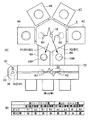
以下に、本発明に係る搬送システムの搬送位置合わせ方法及び処理システムの一実施例を添付図面に基づいて詳述する。図1は本発明方法を実施する搬送システムを含む処理システムの一例を示す概略構成図である。
【0021】
まず、上記処理システムについて説明する。図1に示すように、この処理システム(搬送システム)2は、複数、例えば4つの処理装置4A、4B、4C、4Dと、真空圧雰囲気の略六角形状の共通搬送室6と、ロードロック機能を有する第1及び第2ロードロック室8A、8Bと、大気圧雰囲気の細長い導入側搬送室10とを主に有している。
具体的には、略六角形状の上記共通搬送室6の4辺に上記各処理装置4A〜4Dが接合され、他側の2つの辺に、上記第1及び第2ロードロック室8A、8Bがそれぞれ接合される。そして、この第1及び第2ロードロック室8A、8Bに、上記導入側搬送室10が共通に接続される。
【0022】
上記共通搬送室6と上記4つの各処理装置4A〜4Dとの間及び上記共通搬送室6と上記第1及び第2ロードロック室8A、8Bとの間は、それぞれ気密に開閉可能になされたゲートバルブG1〜G4及びG5、G6が介在して接合されて、クラスタツール化されており、必要に応じて共通搬送室6内と連通可能になされている。また、上記第1及び第2各ロードロック室8A、8Bと上記導入側搬送室10との間にも、それぞれ気密に開閉可能になされたゲートバルブG7、G8が介在されている。
【0023】
上記4つの処理装置4A〜4D内には、それぞれ被処理体としての半導体ウエハを載置するサセプタ12A〜12Dが設けられており、被処理体である半導体ウエハWに対して同種の、或いは異種の処理を施すようになっている。そして、この共通搬送室6内においては、上記2つの各ロードロック室8A、8B及び4つの各処理装置4A〜4Dにアクセスできる位置に、屈伸及び旋回可能になされた多関節アームよりなる第2搬送機構14が設けられており、これは、互いに反対方向へ独立して屈伸できる2つのピックB1、B2を有しており、一度に2枚のウエハを取り扱うことができるようになっている。尚、上記第2搬送機構14として1つのみのピックを有しているものも用いることができる。
【0024】
上記導入側搬送室10は、横長の箱体により形成されており、この横長の一側には、被処理体である半導体ウエハを導入するための1つ乃至複数の、図示例では3つの搬入口16A、16B、16Cが設けられる。そして、この各搬入口16A〜16Cに対応させて、導入ポート18A、18B、18Cがそれぞれ設けられ、ここにそれぞれ1つずつカセット容器20を載置できるようになっている。各カセット容器20には、複数枚、例えば25枚のウエハWを等ピッチで多段に載置して収容できるようになっている。
【0025】
この導入側搬送室10内には、ウエハWをその長手方向に沿って搬送するための導入側搬送機構である第1搬送機構22が設けられる。この第1搬送機構22は、導入側搬送室10内の中心部を長さ方向に沿って延びるように設けた案内レール24上にスライド移動可能に支持されている。この案内レール24には、移動機構として例えばエンコーダを有するリニアモータが内蔵されており、このリニアモータを駆動することにより上記第1搬送機構22は案内レール24に沿って移動することになる。
【0026】
また、導入側搬送室10の一端には、ウエハの位置合わせを行なう位置合わせ機構としてのオリエンタ26が設けられ、更に、導入側搬送室10の長手方向の途中には、前記2つのロードロック室8A、8Bがそれぞれ開閉可能になされた前記ゲートバルブG7、G8を介して設けられる。
上記オリエンタ26は、駆動モータ(図示せず)によって回転される回転台28を有しており、この上にウエハWを載置した状態で回転するようになっている。この回転台28の外周には、ウエハWの周縁部を検出するための光学センサ30が設けられ、これによりウエハWの位置決め切り欠き、例えばノッチやオリエンテーションフラットの位置方向やウエハWの中心の位置ずれ量を検出できるようになっている。
【0027】
また、上記第1搬送機構22は、上下2段に配置された多関節形状になされた2つの搬送アーム32、34を有している。この各搬送アーム32、34の先端にはそれぞれ2股状になされたピックA1、A2を取り付けており、このピックA1、A2上にそれぞれウエハWを直接的に保持するようになっている。従って、各搬送アーム32、34は、この中心より半径方向へ屈伸自在になされており、また、各搬送アーム32、34の屈伸動作は個別に制御可能になされている。上記搬送アーム32、34の各回転軸は、それぞれ基台36に対して同軸状に回転可能に連結されており、例えば基台36に対する旋回方向へ一体的に回転できるようになっている。尚、ここで上記ピックA1、A2は2つではなく、1つのみ設ける場合もある。
【0028】
また、上記第1及び第2ロードロック室8A、8B内には、ウエハWを一時的に載置するための載置台38A、38Bがそれぞれ設置されている。各載置台38A、38Bには、ウエハの受け渡しのために昇降可能になされたリフトピン(図示せず)が設けられている。そして、この処理システム2の動作全体の制御、例えば各搬送機構14、22やオリエンタ26等の動作制御は、例えばマイクロコンピュータ等よりなる制御部40により行われる。
【0029】
次に、先に説明した図1に示す処理システム2を用いて行う実際の位置合わせ方法(ティーチング操作)の第1の実施形態について説明する。
ここでは、各処理装置4A〜4Dの各サセプタ12A〜12Dに対する位置合わせを行う前に、共通搬送室6とオリエンタ26との間で取り得る全ての搬送経路に関する位置合わせを行い、どの搬送経路を経由しても各サセプタ12A〜12D上の同一ポイントに高い位置合わせ精度で搬送できるようにする。この場合、同一場所を搬送機構14、22の相異なるピックでアクセスする場合は、搬送経路は異なるものとする。
まず、図2〜図8は本発明方法による位置合わせ方法(ティーチング操作)の主要部の経路工程を示す図であり、各図には処理システムの模式図に加えて各ピックと各ロードロック室との間の搬送位置座標の確定状況が併せて記載されている。図9、図10は本発明方法の位置合わせ方法を示す工程図である。この位置合わせ方法で用いる位置合わせ用のダミー基板は、前述したように被処理体(前述した被搬送物に対応)である半導体ウエハと直径が同一寸法で厚さも略同じようになされた透明板よりなり、この表面には例えばこのダミー基板をピックで適正な位置で保持した場合にピックが位置すべき場所に予め輪郭等の目印が形成されている。ピック上にダミー基板を適正な位置で保持させる際には、この目印がピックの輪郭と一致するように視認しつつ手で載置して保持させるようになっている。
【0030】
まず、第1工程としてこの処理システム2の全てのピック、すなわち第1搬送機構22の両ピックA1、A2及び第2搬送機構14の両ピックB1、B2のラフティーチングを行う。すなわち粗い位置精度で搬送位置座標を仮決定する(S1)。
このラフティーチングでは、自動移動とマニュアル移動とを適宜組み合わせながら、例えばマニュアル移動ではパルスモータのパルス数を制御しながら印加することによりピックを僅かずつ動かして、上記各ピックA1、A2、B1、B2がアクセスする全ての場所(ポイント)に対して搬送位置座標を仮決定しておく。この搬送位置座標は、当然のこととして、制御部40(図1参照)に記憶されている。このラフティーチング操作では、ピック上に保持されるダミー基板が、各室の内壁等と干渉或いは衝突しない程度の粗い精度で良く、このラフティーチング操作で例えば±2mm以内程度の粗い位置精度でもって搬送位置座標が仮決定される。尚、搬送システムの製造誤差が小さい場合等には、搬送システムの設計数値から搬送位置座標を算出し、これを仮に決定された搬送位置座標とする。
【0031】
ここで仮決定される搬送位置座標は、例えばピックA1、A2のオリエンタ26に対するアクセスポイント、第1及び第2ロードロック室8A、8Bに対する各アクセスポイント、導入ポート18A〜18Cに対する各アクセスポイント及びピックB1、B2の第1及び第2ロードロック室8A、8Bに対する各アクセスポイント、各処理装置4A〜4Dに対する各アクセスポイントである。
【0032】
次に、第2工程に移る。この第2工程では、まず、上記各ピックA1、A2に適正に位置合わせしつつダミー基板DWを支持させ、これを自動でオリエンタ26へ搬送してこの回転台28へ移載する。そして、このダミー基板DWを載置させたまま回転台28を回転することにより光学センサ30でその偏心量を読み取ることによって位置ずれ量を検出する。この時読み取った位置ずれ量に基づいて、すなわちこの位置ずれ量を相殺するように上記ピックの仮決定の搬送位置座標を補正し、これを確定させる(S2)。この操作は、上記両ピックA1、A2に対して個別に行って両ピックA1、A2のオリエンタ26に対する搬送位置座標を確定する。これにより、今後、各ピックA1、A2に適正な位置に支持させたダミー基板DWをオリエンタ26に自動で搬送してこれに移載すると、ダミー基板DWをこの中心が回転台28の中心に一致した状態で移載することが可能となる。
【0033】
次に、第3工程へ移る。この第3工程では、第2搬送機構14のピックB1、B2の第1及び/或いは第2ロードロック室(中継部)8A、8Bに対する搬送位置座標を確定する(S3)。ここでは、図2に示すようにピックB2の第1ロードロック室8Aに対する搬送位置座標と、ピックB1の第1及び第2ロードロック室8A、8Bに対する搬送位置座標を確定し、ピックB2の第2ロードロック室に対する搬送位置座標は仮決定の状態としておく。尚、図2〜図7中において”仮”は搬送位置座標が仮決定にある状態を指し、”決”は搬送位置座標が確定された状態を指す。
【0034】
まず、この第3工程では、一方のピックB2に適正に位置合わせしつつダミー基板DWを支持させ、これを図2(A)中の矢印X1に示すようにマニュアルで第1ロードロック室8Aの載置台38Aまで搬送し、ある程度の位置精度でもって(高い位置精度でなくてもよい)このダミー基板DWを載置台38Aの略中心位置に載置できるようにその搬送座標位置を確定する。これにより、ピックB2の第1ロードロック室8Aの載置台38Aに対するアクセス時の搬送位置座標が確定する。尚、載置台38A上にはダミー基板DWがある程度位置ずれした状態で載置される場合が生ずる。しかし、載置台38Aは、最終目的場所である処理装置4A〜4Dのサセプタ12A〜12Dにウエハを搬送するための中継場所に過ぎず、ダミー基板が最終目的場所の適正な位置で支持されればよいので、載置台38A上におけるダミー基板DWの位置ずれは問題としない。また、仮決定された搬送位置座標が許容範囲内の精度をもっていれば、仮決定された搬送位置座標をそのまま確定する。この考え方は、載置台38Bに関しても同様である。
【0035】
次に、他方のピックB1に適正に位置合わせしつつダミー基板DWを支持させ、これを図2(A)中の矢印X2に示すようにマニュアルで第2ロードロック室8Bの載置台38Bまで搬送し、ある程度の位置精度でもって(高い位置精度でなくてもよい)このダミー基板DWを載置台38Bの略中心位置に載置できるようにその搬送位置座標を確定する。これにより、ピックB1の第2ロードロック室8Bの載置台38Bに対するアクセス時の搬送位置座標が確定する。
次に、この他方のピックB1に適正に位置合わせされて支持されているダミー基板DWを、図2(A)中の矢印X1に示すようにマニュアルで第1ロードロック室8Aの載置台38Aまで搬送し、ある程度の位置精度でもって(高い位置精度でなくてもよい)このダミー基板DWを載置台38Aの略中心位置に載置できるようにその搬送位置座標を確定する。これにより、ピックB1の第1ロードロック室8Aの載置台38Aに対するアクセス時の搬送位置座標が確定する。
尚、上記各ピックB1、B2と各ロードロック室8A、8Bとの間の搬送位置座標の確定順序は上記順序に限定されず、どのような順序でもよい。本実施例では、次の第4工程の操作を考慮して、最後にピックB1の第1ロードロック室8Aの載置台38Aに対する搬送位置座標を決定した。
【0036】
次に、第4工程へ移る。この第4工程では第1ロードロック室8A内のダミー基板DWをオリエンタ26へ自動で搬送する(S4)。具体的には、先の第3工程で、ピックB1を用いてダミー基板DWを第1ロードロック室8Aの載置台38A上にある程度の位置精度で載置したが、ここでは図3に示すようにこの載置台38A上のダミー基板DWを第1搬送機構22の一方のピック、例えばピックA2でアクセスして取りに行き、これを矢印X3に示す搬送経路に沿ってオリエンタ26まで搬送して移載する。ここで注意すべき点は、上記矢印X3に示す搬送経路には仮決定の搬送位置座標としてピックA2の第1ロードロック室8Aの載置台38Aに対するアクセスポイントが1つ含まれている点である。
【0037】
次に、第5工程へ移る。この第5工程では、上記オリエンタ26に移載したダミー基板DWの位置ずれ量を求め、この位置ずれ量に基づいて、すなわち、この位置ずれ量を相殺するように上記ピックA2の載置台38Aに対する仮決定の搬送位置座標を補正し、これを確定する(S5)。これにより、ピックA2の第1ロードロック室8Aの載置台38Aに対する搬送位置座標が確定することになる。尚、図3〜図7中の”補”は、仮決定の搬送位置座標を補正して確定されたアクセスポイントを示す。
【0038】
次に、第6工程へ移る。この第6工程では図4に示すように上記オリエンタ26に載置されているダミー基板DWを、上記位置ずれ量をキャンセルするようにピックA2で取りに行き、これを矢印X4で示す搬送経路に沿って自動で搬送して第1ロードロック室8A内の載置台38A上に載置する。ここではダミー基板DWは、先に載置台38A上に位置決めされた位置に正確に載置されることになる。次に、この載置台38A上のダミー基板DWをピックA1で自動で受け取りに行き、これを矢印X5で示す搬送経路に沿ってオリエンタ26まで搬送して移載する(S6)。この時、注意すべき点は上記矢印X4及びX5で示す搬送経路には仮決定の搬送位置座標としてピックA1の第1ロードロック室8Aの載置台38Aに対するアクセスポイントが1つ含まれている点である。
次に、第7工程へ移る。この第7工程では、上記オリエンタ26に移載したダミー基板DWの位置ずれ量を求め、この位置ずれ量に基づいて、すなわち、この位置ずれ量を相殺するように上記ピックA1の載置台38Aに対する仮決定の搬送位置座標を補正し、これを確定する(S7)。これにより、ピックA1の第1ロードロック室8Aの載置台38Aに対する搬送位置座標が確定することになる。
【0039】
尚、この第6工程及び第7工程におけるピックA1、A2の使用の順序は逆にしてもよく、例えば矢印X4で示す搬送経路の時にピックA1を用い、矢印X5で示す搬送経路の時にピックA2を用いてもよい。
以上の操作により、オリエンタ26上のダミー基板DWをピックA1、或いはA2を用い、第1ロードロック室8Aの載置台38A上に自動で載置した場合、先の第3工程で載置台38A上にてダミー基板DWを位置合わせした場所に再現性良く、つまり同一の位置に高い精度で載置できることになる。
【0040】
次に、第8工程へ移る。この第8工程では図5に示すように、上記オリエンタ26に載置されているダミー基板DWをその位置ずれ量をキャンセルするようにピックA1、或いはA2で自動で取りに行き、これを矢印X6に示す搬送経路に沿って自動で搬送して第1ロードロック室8A内の載置台38A上に移載する。
そして、次に、この載置台38A上のダミー基板DWを第2搬送機構14のピックB1で自動で取りに行き、これを矢印X7に示す搬送経路に沿って自動で搬送して第2ロードロック室8Bの載置台38B上に移載する(S8)。
【0041】
次に、第9工程へ移る。この第9工程では図5に示すように、上記載置台38B上のダミー基板DWを第1搬送機構22のピックA2で取りに行き、これを矢印X8に示す搬送経路に沿って自動で搬送してオリエンタ26へ搬送して移載する(S9)。ここで注意すべき点は、上記矢印X6、X7及びX8で示す搬送経路には仮決定の搬送位置座標としてピックA2の第2ロードロック室8Bの載置台38Bに対するアクセスポイントが1つ含まれている点である。
次に、第10工程へ移る。この第10工程では図5に示すように、上記オリエンタ26に移載したダミー基板DWの位置ずれ量を求め、この位置ずれ量に基づいて、すなわち、この位置ずれ量を相殺するように上記ピックA2の載置台38Bに対する仮決定の搬送位置座標を補正し、これを確定する(S10)。これにより、ピックA2の第2ロードロック室8Bの載置台38Bに対する搬送位置座標が確定することになる。
【0042】
次に、第11工程へ移る。この第11工程では図6に示すように上記オリエンタ26に載置されているダミー基板DWを、その位置ずれ量をキャンセルするようにピックA2で取りに行き、これを矢印X9で示す搬送経路に沿って自動で搬送して第2ロードロック室8B内の載置台38B上に載置する。ここではダミー基板DWは、先に図5(A)で示す載置台38B上に位置決めされた位置に正確に載置されることになる。次に、この載置台38B上のダミー基板DWをピックA1で自動で受け取りに行き、これを矢印X10で示す搬送経路に沿ってオリエンタ26まで搬送して移載する(S11)。この時、注意すべき点は上記矢印X9及びX10で示す搬送経路には仮決定の搬送位置座標としてピックA1の第2ロードロック室8Bの載置台38Bに対するアクセスポイントが1つ含まれている点である。
次に、第12工程へ移る。この第12工程では、上記オリエンタ26に移載したダミー基板DWの位置ずれ量を求め、この位置ずれ量に基づいて、すなわち、この位置ずれ量を相殺するように上記ピックA1の載置台38Bに対する仮決定の搬送位置座標を補正し、これを確定する(S12)。これにより、ピックA1の第2ロードロック室8Bの載置台38Bに対する搬送位置座標が確定することになる。
【0043】
尚、この第11工程及び第12工程におけるピックA1、A2の使用の順序は逆にしてもよく、例えば矢印X9で示す搬送経路の時にピックA1を用い、矢印X10で示す搬送経路の時にピックA2を用いてもよい。
以上の操作により、オリエンタ26上のダミー基板DWをピックA1、或いはA2を用い、第2ロードロック室8Bの載置台38B上に自動で載置した場合、先の第3工程で載置台38B上にてダミー基板DWを位置合わせした場所に再現性良く位置精度が高い状態で載置できることになる。
【0044】
次に、第13工程へ移る。この第13工程では図7に示すように、上記オリエンタ26に載置されているダミー基板DWをその位置ずれ量をキャンセルするようにピックA1、或いはA2で自動で取りに行き、これを矢印X11に示す搬送経路に沿って自動で搬送して第1ロードロック室8A内の載置台38A上に移載する。
そして、次に、この載置台38A上のダミー基板DWを第2搬送機構14のピックB2で自動で取りに行き、これを矢印X12に示す搬送経路に沿って自動で搬送して第2ロードロック室8Bの載置台38B上に移載する(S13)。
【0045】
次に、第14工程へ移る。この第14工程では図7に示すように、上記載置台38B上のダミー基板DWを第1搬送機構22のピックA1、或いはA2で取りに行き、これを矢印X13に示す搬送経路に沿って自動で搬送してオリエンタ26へ搬送して移載する(S14)。ここで注意すべき点は、上記矢印X11、X12及びX13で示す搬送経路には仮決定の搬送位置座標としてピックB2の第2ロードロック室8Bの載置台38Bに対するアクセスポイントが1つ含まれている点である。
次に、第15工程へ移る。この第15工程では、上記オリエンタ26に移載したダミー基板DWの位置ずれ量を求め、この位置ずれ量に基づいて、すなわち、この位置ずれ量を相殺するように上記ピックB2の載置台38Bに対する仮決定の搬送位置座標を補正し、これを確定する(S15)。これにより、ピックB2の第2ロードロック室8Bの載置台38Bに対する搬送位置座標が確定することになる。
【0046】
上記の各工程により、図7(B)に示すように、第1及び第2ロードロック室8A、8Bに対する各ピックA1、A2、B1、B2の全てのアクセスポイントの搬送位置座標は確定することになる。この結果、オリエンタ26上のダミー基板DWをピックB1、B2に搬送する場合、どのような搬送経路、すなわちピックA1、A2のどちらを用いても、また、第1及び第2ロードロック室8A、8Bのどちらを通っても、ピックB1、B2は、各ピック上の同じ位置でダミー基板DWを保持して搬送することができる。
【0047】
次に、第16工程に移る。この第16工程では図8に示すように、オリエンタ26上に載置されているダミー基板DWをその位置ずれ量をキャンセルするように自動で搬出し、これを例えば図8中の矢印X20に示す搬送経路に沿って処理装置4A内のサセプタ12Aまで自動で搬送してこれを移載する(S16)。この時、第2搬送機構14の両ピックB1、B2の内、いずれか一方のピック、例えばピックB1を用いてサセプタ12Aにダミー基板DWを移載する。尚、ピックB1までのダミー基板DWの搬送経路は問わない。
【0048】
次に、第17工程に移る。この第17工程では図8に示すように、サセプタ12A上のダミー基板DWを他方のピックB2で自動で取りに行き、これを矢印X21に示す搬送経路に沿ってオリエンタ26まで自動で搬送し、これを移載する(S17)。
次に、第18工程に移る。この第18工程では図8に示すように、上記オリエンタ26に移載したダミー基板DWの位置ずれ量を求め、この位置ずれ量に基づいて、すなわちこの位置ずれ量を相殺するように、いずれか一方のピック、例えばピックB2の仮決定の搬送位置座標を補正し、これを確定する(S18)。この場合、他方のピックB1の仮決定の搬送位置座標はそのまま搬送位置座標として確定することになる。尚、ここではピックB1とB2の立場を逆にして補正するようにしてもよいし、または求められた位置ずれ量を按分して両者を補正するようにしてもよい。
これにより、両ピックB1、B2のサセプタ12Aに対するアクセスポイントを同じになるように設定することができる。すなわち、ピックB1、B2のいずれを用いた場合であっても、ダミー基板DWをサセプタ12A上の同一ポイントに載置することができる。尚、この場合、サセプタ12Aの中心とダミー基板DWの中心が一致するとは限らない。
【0049】
次に、第19工程に移る。この第19工程では上記したステップS16〜S18の各工程を、他の各処理装置4B〜4Dに対しても同様に行うことにより、各ピックB1、B2の各サセプタ12A〜12Dに対する搬送位置座標を確定することができる(S19)。これにより、各サセプタ12A〜12D上にダミー基板DW、すなわち半導体ウエハを自動で同じ位置に再現性よく正確に載置することが可能となる。
これにより、実際の処理時にカセット容器20から取り出したウエハを各サセプタ12A〜12D上に載置する場合、どのような搬送径路を通っても各サセプタ12A〜12D上の同一位置に再現性良く載置することができる。また、第4工程〜第19工程が人手を介することなく全て自動で行われるので、ティーチング作業のスループットを高めることができる。
上記の例では、第16〜第19工程を第15工程の終了後に行う場合について説明した。しかし、第16〜第19工程は、第1、第2ロードロック室8A,8 Bの少なくとも一方に対する第2搬送機構の2つのピックの搬送位置座標及び当該ロードロック室に対する第1搬送機構の少なくとも一方のピックの搬送位置座標が確定した後であれば、第15工程が完了していなくても行うことができる。
【0050】
尚、上記処理装置に対する位置合わせ方法では、各サセプタ12A〜12Dの中心とダミー基板DWの中心位置とが一致するとは限らないが、実際の処理装置、例えばプラズマ処理装置等においては、サセプタの物理的な中心位置が必ずしも反応の中心位置と一致するとは限らず、装置やプロセス条件等によっては、複数枚の半導体ウエハを処理する毎に、ウエハの処理の面内均一性を確認してこれをフィードバックすることにより、反応中心とウエハ中心とが一致するようにサセプタ上におけるウエハの載置位置を適宜位置調整することが行われている。この場合には、サセプタの中心にウエハの中心位置を一致させて載置することは要求されず、サセプタ上の同じ位置に再現性良くウエハを載置することが要求される。
【0051】
次に、各処理装置4A〜4Dの各サセプタ12A〜12Dの中心とダミー基板DWの中心位置とを一致させる位置合わせ方法について説明する。この位置合わせ方法は、上記の第16〜第19工程に代えて行なう。まず、第15工程終了後にダミー基板DWを1つの処理装置、例えば処理装置4Aのサセプタ12A上に手を用いて適正に位置合わせしつつ載置させる。
【0052】
次に、このサセプタ12A上にダミー基板DWを一方のピック、例えばピックB1で自動で取りに行ってこれを処理装置4Aの外へ搬出し、更に、このダミー基板DWをオリエンタ26まで搬送し、移載する。この時のダミー基板DWの搬送経路はどの経路を用いてもよい。
次に、上記オリエンタ26に移載したダミー基板DWの位置ずれ量を求め、この位置ずれ量に基づいて、すなわち、この位置ずれ量を相殺するように上記ピックB1の処理装置4Aのサセプタ12Aに対する粗い位置精度の搬送位置座標を補正し、これを確定する。これにより、ピックB1の処理装置4Aのサセプタ12Aに対する搬送位置座標が高い位置精度で確定することになる。
【0053】
次に、このオリエンタ26上のダミー基板DWをその位置ずれ量をキャンセルするように搬出して上記ピックB1まで自動で搬送し、これを先の処理装置4Aのサセプタ12A上に載置する。この時点で、上記ピックB1のサセプタ12Aに対する搬送位置座標は既に高い位置精度で確定されているので、ダミー基板DWはその中心がサセプタ12Aの中心に一致するように載置されることになる。
次に、このサセプタ12A上のダミー基板DWを他方のピックB2で自動で取りに行って搬出し、これを自動でオリエンタ26へ搬送して移載する。この時の搬送経路は問わない。
次に、上記オリエンタ26に移載したダミー基板DWの位置ずれ量を求め、この位置ずれ量に基づいて、すなわち、この位置ずれ量を相殺するように上記ピックB2の処理装置4Aのサセプタ12Aに対する仮決定の搬送位置座標を補正し、これを確定する。これにより、ピックB2の処理装置4Aのサセプタ12Aに対する搬送位置座標が高い位置精度で確定することになる。
【0054】
次に、上記した各工程を、他の各処理装置4B〜4Dに対しても同様に行うことにより、各ピックB1、B2の各サセプタ12A〜12Dに対する搬送位置座標を高い位置精度で確定することができる。これにより、各サセプタ12A〜12D上にダミー基板DW、すなわち半導体ウエハを自動で適正な位置に正確に載置することが可能となる。
【0055】
次に、第1搬送機構22の両ピックA1、A2の各導入ポート18A〜18Cに対する位置合わせ方法について説明する。まず、透明なカセット容器20を用意し、このカセット容器20(図1参照)の一部、例えば最下段にダミー基板DWを手で位置合わせしつつ適正な位置に収容し、このカセット容器20を1つの導入ポート、例えば導入ポート18A上の適正な位置に位置合わせしつつ載置する。そして、一方のピック、例えばピックA1をマニュアルで操作して上記カセット容器20内のダミー基板DWを適正な場所で保持できるように位置合わせし、この時のピックA1の座標を搬送位置座標として確定する。
【0056】
そして、他方のピックA2に対しても上記したと同様な操作を行う。このピックA1、A2の高さ方向の位置合わせに関しては、カセット容器内のウエハの存否を調べるマッピング操作の結果に基づいて制御されることになる。
そして、上述したようなピックA1、A2の位置合わせ操作を、他の導入ポート18B、18Cに対しても同様に行うことになる。
【0057】
以上で本発明の第1の実施形態について説明をしたが、本発明は以下に述べる実施形態にも適用できる。
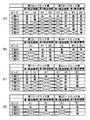
次に、第2の実施形態について説明する。第1の実施形態の第3工程の“決”、“仮”の状態は図2(B)に示されるものに限定されるものではなく、例えば図11(A)の工程A1に示されるものでもよい。工程A1における第2ロードロック室8Bに対するピックA1の搬送位置座標の確定は、仮に決定された載置台38Bの搬送位置座標にダミー基板DWを載置し、これをオリエンタ26に搬送し、ダミー基板DWの位置ずれ量を求め、この位置ずれ量に基き仮に決定された搬送位置座標を補正することにより行なわれる。
【0058】
ティーチングの各工程の動作は第1の実施形態と同様であるので、図11(A)の工程A2〜A6について簡単に説明する。まず、第1実施形態の第4〜第7工程と同様にして第1ロードロック室に対するピックA1及びA2の搬送位置座標が確定される(工程A2、A3)。
次に、オリエンタ26上のダミー基板DWをピックA1で第2ロードロック室8Bに搬送し、次にピックA2でオリエンタ26に移載してダミー基板DWの位置ずれ量を求め、この位置ずれ量に基き第2ロードロック室8Bに対するピックA2の搬送位置座標を確定する(工程A4)。
次に、オリエンタ26上のダミー基板DWをピックA1で第1ロードロック室8Aに搬送し、次にピックB1で第2ロードロック室8Bに搬送し、次にピックA1でオリエンタ26に移載してダミー基板DWの位置ずれ量を求め、この位置ずれ量に基き第2ロードロック室8Bに対するピックB1の搬送位置座標を確定する(工程A5)。第2ロードロック室8Bに対するピックB2の搬送位置座標も同様にして確定する(工程A6)。
【0059】
次に、第3の実施形態について図11(B)を用いて説明する。第1実施形態との相違は、第1搬送機構22のピックが1つだけであることである。第1、第 2の実施形態と同様にして各ピックの“決”、“仮”が行われ、ダミー基板DWは第2ロードロック室8B内の載置台38Bに載置されている(工程B1)。
まず、ダミー基板DWをピックA1でオリエンタ26に移載し、ダミー基板DWの位置ずれ量を求め、この位置ずれ量に基き第2ロードロック室8Bに対するピックA1の搬送位置座標を確定する(工程B2)。
次に、ダミー基板DWをピックA1で第1ロードロック室8Aに搬送し、次にピックB1で第2ロードロック室8Bに搬送し、次にピックA1でオリエンタ26に移載してダミー基板DWの位置ずれ量を求め、この位置ずれ量に基き第1ロードロック室8Aに対するピックB1の搬送位置座標を確定する(工程B3)。第1ロードロック室8Aに対するピックB2の搬送位置座標も同様にして確定する(工程B4)。
【0060】
次に、第4の実施形態について図11(C)を用いて説明する。第1実施形態との相違は、第2搬送機構14のピックが1つだけであることである。第1、第 2実施形態と同様にして各ピックの“決”、“仮”が行われ、ダミー基板DWは第1ロードロック室8A内の載置台38Aに載置されている(工程C1)。
まず、第1実施形態の第4〜第7工程と同様にして第1ロードロック室に対するピックA1及びA2の搬送位置座標が確定される(工程C2、C3)。次に、オリエンタ26上のダミー基板DWをピックA1で第1ロードロック室8Aに搬送し、次にピックB1により第2ロードロック室8Bに搬送し、次にピックA1でオリエンタ26に移載してダミー基板DWの位置ずれ量を求め、この位置ずれ量に基き第2ロードロック室8Bに対するピックB1の搬送位置座標を確定する(工程C4)。次に、ダミー基板DWをピックA1で第2ロードロック室8Bに搬送し、次にピックA2でオリエンタ26に移載してダミー基板DWの位置ずれ量を求め、この位置ずれ量に基き第2ロードロック室8Bに対するピックA2の搬送位置座標を確定する(工程C5)。
【0061】
次に、第5の実施形態について図11(D)を用いて説明する。第1実施形態との相違は、第1、第2搬送機構22、14のピックが共に1つだけであることである。第1、第2実施形態と同様にして各ピックの“決”、“仮”が行われ、 ダミー基板DWは第1ロードロック室8A内の載置台38AのピックB1の仮に決定された搬送位置座標に載置されている(工程D1)。
まず、ダミー基板DWをピックA1でオリエンタ26に移載し、ダミー基板DWの位置ずれ量を求め、この位置ずれ量に基き第1ロードロック室8Aに対するピックB1の搬送位置座標を確定する(工程D2)。
次に、ダミー基板DWをピックA1で第1ロードロック室8Aに搬送し、次にピックB1で第2ロードロック室8Bに搬送し、次にピックA1でオリエンタ26に移載してダミー基板DWの位置ずれ量を求め、この位置ずれ量に基き第2ロードロック室8Bに対するピックB1の搬送位置座標を確定する(工程D3)。
【0062】
次に、第6の実施形態について説明する。上記実施例にあっては、共通搬送室6を1つ設けた場合の処理システムについて説明したが、この処理システムの形態はどのようなものでもよい。
例えば図12は処理システムの変形例を示す概略構成図である。ここでは、先の共通搬送室6に半導体ウエハを載置することができるバッファ載置台50を介してもう1つの略六角形状の共通搬送室52を連結させて設けている。
この場合、前段の共通搬送室6には2つの処理装置4A、4Dが連設され、他方の後段の共通搬送室52には4つの処理装置4E、4F、4G、4Hがそれぞれ連結されている。そして、各処理装置4E〜4H内にはそれぞれサセプタ12E〜12Hが設置されている。また、この後段の共通搬送室52内には前記第2搬送機構6と同様な構成の第3搬送機構54が設けられると共に、この第3搬送機構54は2つのピックC1、C2を有している。
この場合、前段と後段の共通搬送室6、52間のウエハの搬送は上記バッファ載置台50を介して行う。
【0063】
さて、図12に示すような処理システムにおいて位置合わせを行う場合には、前段の共通搬送室6、第1及び第2ロードロック室8A、8Bに関しては前述したと同様に行い、そして、バッファ載置台50に対しても、他の処理装置、例えば処理装置4Aに対して行ったと同様な操作を行う。
そして、第3搬送機構54のピックC1、C2のバッファ載置台50に対する搬送位置座標を確定するには、これらのピックC1、C2に手でダミー基板DWを適正に位置合わせしつつ保持させ、これをバッファ載置台50にマニュアルで適正な場所に載置させるようにしてそれぞれ搬送位置座標を確定する。
【0064】
次に、オリエンタ26からダミー基板DWを搬送してこれを一方のピック、例えばピックC1を用いて処理装置4E内へ搬入して移載し、次に、このダミー基板DWを他方のピックC2を用いて取り出し、これをオリエンタ26まで搬送し、その位置ずれ量を求める。そして、この位置ずれ量を相殺するようにピックC1、C2のいずれか一方または両方の仮決定の搬送位置座標を補正して確定する。そして、このような操作を他の全ての処理装置4F〜4Hに対して行えばよい。
ここでは、ロードロック室が2つである場合を例にとって説明したが、これに限定されず、3つ以上である場合にも本発明方法を適用できるのは勿論である。また、被処理体として半導体ウエハを例にとって説明したが、これに限定されず、ガラス基板、LCD基板等の場合にも本発明方法を適用できるのは勿論である。
【0065】
【発明の効果】
以上説明したように、本発明の搬送システムの搬送位置合わせ方法及び処理システムによれば次のように優れた作用効果を発揮することができる。
被搬送物の搬送すべき位置として粗い精度で決定されていた搬送位置座標を、位置合わせ機構を用いてその位置ずれ量を求めて補正することにより搬送位置座標を1つずつ確定するようにしたので、位置決め精度の高いティーチング操作を迅速に行うことができる。また、オペレータにとって負担の大きいマニュアルによる位置合わせ操作を行う箇所が少なくて済むので、その分、オペレータの負担を大幅に低減することができる。
【図面の簡単な説明】
【図1】本発明方法を実施する搬送システムを含む処理システムの一例を示す概略構成図である。
【図2】本発明方法による位置合わせ方法(ティーチング操作)の主要部の経路工程を示す図である。
【図3】本発明方法による位置合わせ方法(ティーチング操作)の主要部の経路工程を示す図である。
【図4】本発明方法による位置合わせ方法(ティーチング操作)の主要部の経路工程を示す図である。
【図5】本発明方法による位置合わせ方法(ティーチング操作)の主要部の経路工程を示す図である。
【図6】本発明方法による位置合わせ方法(ティーチング操作)の主要部の経路工程を示す図である。
【図7】本発明方法による位置合わせ方法(ティーチング操作)の主要部の経路工程を示す図である。
【図8】本発明方法による位置合わせ方法(ティーチング操作)の経路工程を示す図である。
【図9】本発明方法の位置合わせ方法を示す工程図である。
【図10】本発明方法の位置合わせ方法を示す工程図である。
【図11】本発明方法の他の位置合わせ方法を示す工程表である。
【図12】処理システムの変形例を示す概略構成図である。
【符号の説明】
2 処理システム
4A〜4D 処理装置(処理部)
8A 第1ロードロック室(中継部、載置部)
8B 第2ロードロック室(中継部、載置部)
10 導入側搬送室
12A〜12D サセプタ(載置部)
14 第2搬送機構
18A〜18C 導入ポート
22 第1搬送機構
26 オリエンタ(位置合わせ機構)
40 制御部
A1,A2,B1,B2 ピック
DW ダミー基板(位置合わせ用基板)[0001]
BACKGROUND OF THE INVENTION
The present invention relates to a positioning method of a transfer system for transferring an object to be processed such as a semiconductor wafer. And processing system About.
[0002]
[Prior art]
Generally, in order to manufacture a semiconductor integrated circuit, various processes such as film formation, etching, oxidation, and diffusion are performed on a wafer. In order to improve throughput and yield by miniaturization and high integration of a semiconductor integrated circuit, a plurality of processing apparatuses performing the same process or a plurality of processing apparatuses performing different processes are connected through a common transfer chamber. A so-called clustered processing system apparatus which is coupled to each other and enables continuous processing of various processes without exposing the wafer to the atmosphere is disclosed in Patent Document 1.
[0003]
In this type of processing system, for example, a semiconductor wafer is taken out from a cassette container installed at an introduction port of an object to be processed provided in the previous stage of the processing system by using a transfer mechanism, and this is taken into an introduction side transfer chamber of the processing system. After the wafer is aligned by an alignment mechanism, the wafer is loaded into a load lock chamber that can be evacuated, and the wafer is further connected to a vacuum in which a plurality of vacuum processing apparatuses are connected to the surroundings. The wafer is carried into a common transfer chamber in an atmosphere by using another transfer mechanism, and the wafer is sequentially introduced into each vacuum processing apparatus with the common transfer chamber as a center so that the processing is continuously performed. Then, the processed wafer is accommodated in the original cassette container through the original path, for example.
By the way, as described above, this type of processing system has one or a plurality of transfer mechanisms therein, and wafer transfer and transfer are automatically performed by these transfer mechanisms.
[0004]
This transport mechanism has one or two picks that can be bent, swung, and raised and lowered, for example, and directly holds the wafer with this pick and moves it horizontally to the transport position to move the wafer to a predetermined position. It is supposed to be transported up to.
In this case, it is necessary not only to prevent the picking or holding wafer from interfering with or colliding with other members during the operation of the transfer mechanism, but also to properly hold the wafer placed at a certain place. In addition, it is necessary to transport the wafer to a target position and deliver it to an appropriate place with high accuracy, for example, with high positional accuracy within ± 0.20 mm.
[0005]
For this reason, when the apparatus is assembled or when a large apparatus is remodeled, the operation of the transfer mechanism is controlled at an important position such as a place where the wafer W is transferred in the pick movement path of the transfer mechanism. A so-called teaching operation is performed in which a control unit such as a computer memorizes the conveyance position coordinates.
This teaching includes, for example, the positional relationship between the transport mechanism and the cassette container, the positional relationship between the loading table of the load lock chamber and the pick, the positional relationship between the pick and the alignment mechanism, and the positional relationship between the pick and the susceptor of each vacuum processing apparatus. In almost all cases for transferring a wafer, that is, for each place (point) where the pick accesses, the transfer position coordinates are stored. All drive systems have built-in encoders for specifying the drive position, and the drive system includes a pulse motor, for example, to control the number of pulses, thereby accurately controlling the amount of movement. Of course you can.
[0006]
A conventional conveying system teaching method in a clustered processing system is disclosed in
First, before performing a teaching operation with high position accuracy, the transport position coordinates are provisionally determined in advance with rough accuracy. This is fine enough to prevent the wafer from colliding with the inner wall or the like even if the wafer is automatically transferred. For example, the transfer position coordinates are temporarily determined with a transfer error of about ± 2 mm.
[0007]
Next, the above-described dummy substrate is placed at an appropriate position with high positional accuracy while being manually aligned with a transfer position such as on a placing table in the load lock chamber or on a susceptor in the vacuum processing chamber. Then, the dummy substrate is transported to an orienter that is a positioning mechanism by driving the pick to rotate, bend and stretch, and the misalignment amount is detected by the orienter. By correcting the coordinates of the transport position temporarily determined based on the amount of positional deviation, the transport position coordinates are stored in the control unit and determined. Then, the teaching operation as described above is performed for each individual pick over all the places where the pick accesses.
[0008]
[Patent Document 1]
JP 2000-208589 A
[Patent Document 2]
Japanese Patent Laid-Open No. 2000-127069
[0009]
[Problems to be solved by the invention]
By the way, in the teaching operation as described above, since the operator must carefully perform the alignment for every place accessed by each pick while manually observing the pick, it takes a long time for the teaching operation. In addition to this, there is a problem that it is a heavy burden on the operator. In addition, as a result of performing the above-described manual operation over all the places where the picks access and for each individual pick, when the wafer taken out from the cassette is transferred onto the susceptor of the processing chamber, the transfer path through which the wafer passes is determined. There is also a problem that the position of the wafer placed on the susceptor slightly varies.
[0010]
The present invention has been devised to pay attention to the above problems and to effectively solve them. It is an object of the present invention to correct a high-accuracy conveyance position coordinate by correcting a coarse conveyance position coordinate with a coarse alignment accuracy, which is temporarily determined by so-called rough teaching, one by one using an alignment mechanism such as an orienter. As a result, it is possible to reduce the number of places where the operator manually adjusts with high positional accuracy, to perform the teaching operation quickly, and high accuracy at the same position on the susceptor without depending on the transfer path through which the wafer passes. Method for positioning a transport system that can be mounted with And processing system Is to provide.
[0011]
[Means for Solving the Problems]
The invention according to claim 1 includes an alignment mechanism that detects a positional deviation amount of the center position of the mounted object to be transported, and first and second relay units for relaying the object to be transported during transportation. At least one pick for holding the object to be conveyed, and having at least one pick for holding the object to be conveyed, and a first conveying mechanism accessible to the alignment mechanism and the first and second relay parts. And transporting the object to be transported of each pick of each transport mechanism in a transport position adjusting method of a transport system having a second transport mechanism accessible to the first and second relay units. Tentatively determining the transport position coordinates with coarse accuracy, a first determination step for determining the transport position coordinates of each pick of the first transport mechanism with respect to the alignment mechanism, and the respective transport with respect to other than the alignment mechanism mechanism A second determining step for determining a part of the transport position coordinates of the transport position coordinates of each pick, and a transport object for alignment through a transport path that passes through one point of the transport position coordinates that has been temporarily determined. A third determination step for determining the amount of positional deviation based on the amount of positional deviation, and determining the provisionally determined conveyance position coordinates, and the provisionally determined conveyance position. And a fourth confirmation step in which the third confirmation step is repeated until all the coordinates are confirmed.
[0012]
Thus, after temporarily determining the transfer position coordinates of the point to which the object is to be transferred with rough position accuracy and determining some transfer position coordinates with a predetermined accuracy, Since the object to be conveyed is conveyed to the alignment mechanism via the conveyance path passing through one point, and the position deviation amount is determined and corrected, the conveyance position coordinates are sequentially determined one by one. It is possible to reduce teaching operations with predetermined position accuracy or high position accuracy by manual operation. In addition, it is possible to indirectly determine the transfer position coordinate related to the second transfer mechanism that cannot directly access the alignment mechanism by using the fixed transfer position coordinate related to the first transfer mechanism. The first and second transfer mechanisms and the relay unit here are, for example, a transfer mechanism provided in an atmospheric transfer chamber in a cluster system, a transfer mechanism provided in a vacuum common transfer chamber, and a load lock provided between both transfer chambers. It corresponds to each room.
[0013]
In this case, for example, as defined in
In this way, the transported object is transported along a path that circulates in the forward direction or the reverse direction through the positioning mechanism and the first and second relay units, and the temporarily determined transport position coordinates are sequentially determined. Therefore, even if the object to be transported is transported to either the first or second relay section by the first transport mechanism, or is transported by any pick of the first transport mechanism, Each pick of the two transport mechanism can hold the object to be transported in the first and second relay sections at the same place on the pick.
[0014]
In this case, for example, as defined in
[0015]
In this case, for example, as defined in claim 4, the transport system further includes a processing unit for processing the transported object disposed at a position accessible by the second transport mechanism, and The two transport mechanism has two picks, and the transport position coordinates of two picks of the second transport mechanism with respect to at least one relay unit and the transport position coordinates of at least one pick of the first transport mechanism with respect to the relay unit are determined. Later, the step of transporting the object to be aligned to the transport position coordinates temporarily determined by the first pick with respect to the processing unit by the first pick of the second transport mechanism, and the object to be aligned for alignment Unloading from the transport position coordinates temporarily determined for the second pick with respect to the processing unit by the second pick of the second transport mechanism and further transporting to the alignment mechanism; A positional deviation amount of the object for alignment is obtained by an alignment mechanism, and based on the positional deviation amount, the conveyance position coordinates of either one or both of the second conveyance mechanisms with respect to the processing unit are corrected, And determining the transport position coordinates of the two picks.
Therefore, when the object to be transported is further transported to, for example, the processing device of the cluster system through the first transport mechanism, the first and second relay units, and the second transport mechanism, the processing device etc. The transferred object can be transferred to the same place.
[0016]
In this case, for example, as defined in
Accordingly, the transported object stored in the storage unit is taken out by the first transport mechanism, and is transferred to, for example, a processing apparatus of the cluster system via the first transport mechanism, the first and second relay units, and the second transport mechanism. In the case of further transport, the transported object can be transferred to the same place such as a processing apparatus even if the transport path is different.
[0017]
According to a sixth aspect of the present invention, there is provided an alignment mechanism for detecting a positional deviation amount of the center position of the placed object to be conveyed, and for placing the object to be conveyed at the time of conveyance. The relay section of In a transport position alignment method of a transport system having a transport mechanism having two picks for holding the transported object, the transport position coordinates of each pick of the transport mechanism when transporting the transported object with coarse accuracy. Temporarily determining and determining the transport position coordinates of each pick of the transport mechanism relative to the alignment mechanism A first determination step and the relay unit A step of placing the object to be aligned at a normal position, transporting the object to be aligned to the alignment mechanism by the first pick of the conveyance mechanism, and the object to be aligned by the alignment mechanism. Obtain the amount of misalignment of the conveyed product, and based on this misalignment amount, In the relay section Determine the transport position coordinates of the first pick of the transport mechanism The second confirmation step The object to be aligned placed on the alignment mechanism is moved forward by either pick of the transfer mechanism. Carry to the relay section Sending process, The above-mentioned mounted on the relay unit A step of transporting the object to be aligned to the alignment mechanism by the other pick of the transport mechanism, and a positional deviation amount of the object to be aligned for alignment is obtained by the registration mechanism, and based on this positional deviation amount. Before To the relay section And a step of determining the transport position coordinates of the second pick of the transport mechanism.
[0018]
In this way, the first and second picks of the transport mechanism serve as the parts to be transported. (Relay part) When accessing, the transport position coordinates of one pick relative to the placement unit are determined using the alignment mechanism, and the transport position coordinates of the other pick are determined using the determined transport position coordinates. Whichever pick is used, the object to be transported can be placed at the same position on the placement portion. For example, a mounting table in a load lock chamber in a cluster system, a susceptor in a processing apparatus, and the like correspond to the mounting unit. In addition, the operation of placing the object to be conveyed at the normal position of the placement unit may be performed manually or by transfer by another conveyance mechanism.
[0019]
In this case, for example, as defined in
The invention defined in
[0020]
DETAILED DESCRIPTION OF THE INVENTION
In the following, the transfer position adjusting method of the transfer system according to the present invention And processing system One embodiment will be described in detail with reference to the accompanying drawings. FIG. 1 is a schematic configuration diagram showing an example of a processing system including a transport system for carrying out the method of the present invention.
[0021]
First, the processing system will be described. As shown in FIG. 1, this processing system (transfer system) 2 includes a plurality of, for example, four
Specifically, the
[0022]
The
[0023]
In each of the four
[0024]
The introduction-
[0025]
In the introduction-
[0026]
Further, an
The
[0027]
The
[0028]
In addition, in the first and second
[0029]
Next, a first embodiment of an actual alignment method (teaching operation) performed using the
Here, before performing alignment with respect to each susceptor 12A-12D of each
First, FIGS. 2 to 8 are views showing the route process of the main part of the alignment method (teaching operation) according to the method of the present invention. Each figure includes each pick and each load lock chamber in addition to the schematic diagram of the processing system. The confirmation status of the transfer position coordinates between the two is also described. 9 and 10 are process diagrams showing the alignment method of the method of the present invention. As described above, the alignment dummy substrate used in this alignment method is a transparent plate having the same diameter and the same thickness as the semiconductor wafer as the object to be processed (corresponding to the object to be transferred). In this surface, for example, when the dummy substrate is held at an appropriate position by a pick, a mark such as a contour is formed in advance at a position where the pick is to be located. When the dummy substrate is held at an appropriate position on the pick, the mark is visually placed so as to coincide with the outline of the pick and placed and held by hand.
[0030]
First, as a first step, rough picking is performed on all picks of the
In this rough teaching, the pick is moved little by little while applying an appropriate combination of automatic movement and manual movement, for example, while controlling the number of pulses of the pulse motor in manual movement, and the picks A1, A2, B1, B2 The transport position coordinates are provisionally determined for all the locations (points) accessed by. As a matter of course, the transport position coordinates are stored in the control unit 40 (see FIG. 1). In this rough teaching operation, the dummy substrate held on the pick may have a rough accuracy so that it does not interfere with or collide with the inner wall of each chamber, etc., and this rough teaching operation carries with a rough positional accuracy of, for example, about ± 2 mm. Position coordinates are provisionally determined. When the manufacturing error of the transport system is small, the transport position coordinates are calculated from the design values of the transport system, and are set as the temporarily determined transport position coordinates.
[0031]
The transport position coordinates temporarily determined here are, for example, an access point for the
[0032]
Next, the process proceeds to the second step. In this second step, first, the dummy substrate DW is supported while properly aligning with each of the picks A1 and A2, and this is automatically conveyed to the
[0033]
Next, the process proceeds to the third step. In this third step, the transfer position coordinates for the first and / or second load lock chambers (relay units) 8A, 8B of the picks B1, B2 of the
[0034]
First, in the third step, the dummy substrate DW is supported while being properly aligned with one pick B2, and this is manually set in the first
[0035]
Next, the dummy substrate DW is supported while properly aligning with the other pick B1, and this is manually transferred to the mounting table 38B of the second
Next, the dummy substrate DW that is properly aligned and supported by the other pick B1 is manually moved to the mounting table 38A of the first
The order of determining the transfer position coordinates between the picks B1 and B2 and the
[0036]
Next, the process proceeds to the fourth step. In this fourth step, the dummy substrate DW in the first
[0037]
Next, the process proceeds to the fifth step. In the fifth step, the amount of positional deviation of the dummy substrate DW transferred to the
[0038]
Next, the process proceeds to the sixth step. In this sixth step, as shown in FIG. 4, the dummy substrate DW placed on the
Next, the process proceeds to the seventh step. In this seventh step, the positional deviation amount of the dummy substrate DW transferred to the
[0039]
The order of use of the picks A1 and A2 in the sixth process and the seventh process may be reversed. For example, the pick A1 is used when the transport path is indicated by the arrow X4, and the pick A2 is used when the transport path is indicated by the arrow X5. May be used.
With the above operation, when the dummy substrate DW on the
[0040]
Next, the process proceeds to the eighth step. In the eighth step, as shown in FIG. 5, the dummy substrate DW placed on the
Then, the dummy substrate DW on the mounting table 38A is automatically picked up by the pick B1 of the
[0041]
Next, the process proceeds to the ninth step. In the ninth step, as shown in FIG. 5, the dummy substrate DW on the mounting table 38B is picked up by the pick A2 of the
Next, the process proceeds to the tenth step. In the tenth step, as shown in FIG. 5, the positional deviation amount of the dummy substrate DW transferred to the
[0042]
Next, the process proceeds to the eleventh step. In this eleventh step, as shown in FIG. 6, the dummy substrate DW placed on the
Next, the process proceeds to the twelfth process. In the twelfth step, the positional deviation amount of the dummy substrate DW transferred to the
[0043]
The order of use of the picks A1 and A2 in the eleventh step and the twelfth step may be reversed. For example, the pick A1 is used for the transport route indicated by the arrow X9, and the pick A2 is used for the transport route indicated by the arrow X10. May be used.
By the above operation, when the dummy substrate DW on the
[0044]
Next, the process proceeds to the thirteenth step. In the thirteenth step, as shown in FIG. 7, the dummy substrate DW placed on the
Next, the dummy substrate DW on the mounting table 38A is automatically picked up by the pick B2 of the
[0045]
Next, the process proceeds to the 14th step. In the fourteenth step, as shown in FIG. 7, the dummy substrate DW on the mounting table 38B is picked up by the pick A1 or A2 of the
Next, the process proceeds to the fifteenth process. In this fifteenth step, the amount of positional deviation of the dummy substrate DW transferred to the
[0046]
As shown in FIG. 7B, the transfer position coordinates of all the access points of the picks A1, A2, B1, and B2 with respect to the first and second
[0047]
Next, the process proceeds to the sixteenth step. In the sixteenth step, as shown in FIG. 8, the dummy substrate DW placed on the
[0048]
Next, the process moves to the 17th step. In this seventeenth step, as shown in FIG. 8, the dummy substrate DW on the
Next, the process proceeds to the 18th step. In this eighteenth step, as shown in FIG. 8, the amount of positional deviation of the dummy substrate DW transferred to the
Thereby, the access points for the
[0049]
Next, it moves to the 19th step. In the nineteenth step, the above-described steps S16 to S18 are similarly performed on the
As a result, when a wafer taken out from the
In the above example, the case where the 16th to 19th steps are performed after the end of the 15th step has been described. However, the sixteenth to nineteenth steps include the transfer position coordinates of the two picks of the second transfer mechanism with respect to at least one of the first and second
[0050]
In the alignment method for the processing apparatus, the center of each of the
[0051]
Next, an alignment method for matching the centers of the
[0052]
Next, the dummy substrate DW is automatically picked up by one pick, for example, pick B1, on the
Next, the positional deviation amount of the dummy substrate DW transferred to the
[0053]
Next, the dummy substrate DW on the
Next, the dummy substrate DW on the
Next, the positional deviation amount of the dummy substrate DW transferred to the
[0054]
Next, the above-described steps are similarly performed on the
[0055]
Next, an alignment method for the
[0056]
The same operation as described above is performed for the other pick A2. The alignment of the picks A1 and A2 in the height direction is controlled based on the result of a mapping operation for examining the presence or absence of a wafer in the cassette container.
Then, the positioning operation of the picks A1 and A2 as described above is similarly performed on the
[0057]
Although the first embodiment of the present invention has been described above, the present invention can also be applied to the embodiments described below.
Next, a second embodiment will be described. The “determined” and “provisional” states in the third step of the first embodiment are not limited to those shown in FIG. 2B, for example, those shown in step A1 in FIG. But you can. In the step A1, the transfer position coordinates of the pick A1 with respect to the second
[0058]
Since the operation of each teaching step is the same as in the first embodiment, steps A2 to A6 in FIG. First, similarly to the fourth to seventh steps of the first embodiment, the transfer position coordinates of the picks A1 and A2 with respect to the first load lock chamber are determined (steps A2 and A3).
Next, the dummy substrate DW on the
Next, the dummy substrate DW on the
[0059]
Next, a third embodiment will be described with reference to FIG. The difference from the first embodiment is that there is only one pick of the
First, the dummy substrate DW is transferred to the
Next, the dummy substrate DW is transported to the first
[0060]
Next, a fourth embodiment will be described with reference to FIG. The difference from the first embodiment is that the
First, similarly to the fourth to seventh steps of the first embodiment, the transfer position coordinates of the picks A1 and A2 with respect to the first load lock chamber are determined (steps C2 and C3). Next, the dummy substrate DW on the
[0061]
Next, a fifth embodiment will be described with reference to FIG. The difference from the first embodiment is that there is only one pick for each of the first and
First, the dummy substrate DW is transferred to the
Next, the dummy substrate DW is transported to the first
[0062]
Next, a sixth embodiment will be described. In the above embodiment, the processing system in which one
For example, FIG. 12 is a schematic configuration diagram showing a modification of the processing system. Here, another common hexagonal
In this case, two
In this case, wafer transfer between the front and rear
[0063]
When the alignment is performed in the processing system as shown in FIG. 12, the
In order to determine the transport position coordinates of the picks C1 and C2 of the third transport mechanism 54 with respect to the buffer mounting table 50, the picks C1 and C2 are held by appropriately aligning and holding the dummy substrate DW by hand. Are respectively placed on an appropriate place on the buffer mounting table 50 to determine the transport position coordinates.
[0064]
Next, the dummy substrate DW is transported from the
Here, the case where there are two load lock chambers has been described as an example. However, the present invention is not limited to this, and it is needless to say that the method of the present invention can be applied even when there are three or more load lock chambers. Although the semiconductor wafer has been described as an example of the object to be processed, the present invention is not limited to this, and it is needless to say that the method of the present invention can be applied to a glass substrate, an LCD substrate, or the like.
[0065]
【The invention's effect】
As described above, the conveyance position alignment method and processing system of the conveyance system of the present invention. To According to this, the following excellent effects can be exhibited.
The transport position coordinates determined with coarse accuracy as the position to be transported of the object to be transported are determined and corrected one by one by obtaining and correcting the positional deviation amount using the alignment mechanism. Therefore, teaching operation with high positioning accuracy can be performed quickly. In addition, since there are few places for manual alignment operations that are burdensome for the operator, the burden on the operator can be greatly reduced.
[Brief description of the drawings]
FIG. 1 is a schematic configuration diagram showing an example of a processing system including a transfer system that implements a method of the present invention.
FIG. 2 is a diagram showing a path process of a main part of an alignment method (teaching operation) according to the method of the present invention.
FIG. 3 is a diagram showing a path process of a main part of an alignment method (teaching operation) according to the method of the present invention.
FIG. 4 is a diagram showing a path process of a main part of an alignment method (teaching operation) according to the method of the present invention.
FIG. 5 is a diagram showing a path process of a main part of an alignment method (teaching operation) according to the method of the present invention.
FIG. 6 is a diagram showing a path process of a main part of an alignment method (teaching operation) according to the method of the present invention.
FIG. 7 is a diagram showing a path process of a main part of an alignment method (teaching operation) according to the method of the present invention.
FIG. 8 is a diagram showing a path process of an alignment method (teaching operation) according to the method of the present invention.
FIG. 9 is a process diagram showing an alignment method of the method of the present invention.
FIG. 10 is a process diagram showing an alignment method of the method of the present invention.
FIG. 11 is a process chart showing another alignment method of the method of the present invention.
FIG. 12 is a schematic configuration diagram showing a modification of the processing system.
[Explanation of symbols]
2 Processing system
4A to 4D processing device (processing unit)
8A 1st load lock chamber (relay part, placement part)
8B Second load lock chamber (relay part, placement part)
10 Introduction side transfer chamber
12A-12D susceptor (mounting part)
14 Second transport mechanism
18A-18C introduction port
22 First transport mechanism
26 Oriental (alignment mechanism)
40 Control unit
A1, A2, B1, B2 pick
DW dummy board (positioning board)
Claims (8)
前記各搬送機構の各ピックの、前記被搬送物を搬送するときの搬送位置座標を粗い精度で仮に決定する工程と、
前記位置合わせ機構に対する前記第1搬送機構の各ピックの搬送位置座標を確定する第1確定工程と、
前記位置合わせ機構以外に対する前記各搬送機構の各ピックの搬送位置座標の内の一部の搬送位置座標を確定する第2確定工程と、
位置合わせ用搬送物を、仮に決定されている搬送位置座標のポイントを1つ通る搬送経路を経由して前記位置合わせ機構へ搬送して、その位置ずれ量を求め、この位置ずれ量に基づいて前記仮に決定されている搬送位置座標を確定する第3確定工程と、
前記仮に決定されている搬送位置座標が全て確定されるまで前記第3確定工程を繰り返して行う第4確定工程と、
を有することを特徴とする搬送システムの搬送位置合わせ方法。A positioning mechanism for detecting the amount of misalignment of the center position of the object to be transported, first and second relay parts for relaying the object to be transported during transport, and a pick for holding the object to be transported And at least one pick for holding the object to be transported, and the first transport mechanism accessible to the positioning mechanism and the first and second relay parts, and the first In the transport position adjusting method of the transport system having the second transport mechanism accessible to the second relay unit,
Tentatively determining the transport position coordinates of each pick of each transport mechanism when transporting the object to be transported with coarse accuracy;
A first determination step of determining a transfer position coordinate of each pick of the first transfer mechanism with respect to the alignment mechanism;
A second determination step of determining a part of the transport position coordinates of the transport position coordinates of each pick of each of the transport mechanisms with respect to other than the alignment mechanism;
The alignment object is conveyed to the alignment mechanism via a conveyance path that passes through one point of the conveyance position coordinates that has been temporarily determined, and the positional deviation amount is obtained. Based on the positional deviation amount, A third determination step for determining the provisionally determined transport position coordinates;
A fourth determination step that repeats the third determination step until all the transport position coordinates that are temporarily determined are determined;
A transport position adjusting method for a transport system, comprising:
少なくとも一方の中継部に対する第2搬送機構の2つのピックの搬送位置座標及び当該中継部に対する第1搬送機構の少なくとも一方のピックの搬送位置座標が確定した後に、前記位置合わせ用被搬送物を前記第2搬送機構の第1ピックにより前記処理部に対する前記第1ピックの仮に決定された搬送位置座標に搬送する工程と、
この位置合わせ用被搬送物を前記第2搬送機構の第2ピックにより前記処理部に対する前記第2ピックの仮に決定された搬送位置座標から搬出し、更に前記位置合わせ機構に搬送する工程と、
前記位置合わせ機構により前記位置合わせ用被搬送物の位置ずれ量を求め、この位置ずれ量に基いて前記処理部に対する前記第2搬送機構のいずれか一方または両方のピックの搬送位置座標を補正し、且つ前記両ピックの搬送位置座標を確定する工程と、
を有することを特徴とする請求項1乃至3のいずれか一項に記載の搬送システムの搬送位置合わせ方法。The transport system further includes a processing unit for processing the transported object disposed at a position accessible by the second transport mechanism, and the second transport mechanism has two picks,
After the transport position coordinates of the two picks of the second transport mechanism with respect to at least one relay section and the transport position coordinates of at least one pick of the first transport mechanism with respect to the relay section are determined, the transport object for alignment is Transporting to the transport position coordinates temporarily determined by the first pick for the processing unit by the first pick of the second transport mechanism;
A step of unloading the object for alignment from the conveyance position coordinate temporarily determined by the second pick with respect to the processing unit by the second pick of the second transport mechanism, and further transporting it to the alignment mechanism;
The positional adjustment mechanism obtains a positional deviation amount of the object to be aligned, and corrects the conveyance position coordinates of one or both picks of the second conveyance mechanism with respect to the processing unit based on the positional deviation amount. And determining the transfer position coordinates of the two picks;
Conveying alignment method of claims 1 to 3 transport system of placing serial to any one characterized by having a.
前記収納部に収納された前記位置合せ用被搬送物に対する前記第1搬送機構の各ピックの搬送位置座標を確定する工程を更に有することを特徴とする請求項4に記載の搬送システムの搬送位置合わせ方法。The transport system further includes a storage unit for storing the transported object disposed at a position accessible by the first transport mechanism,
5. The transport position of the transport system according to claim 4, further comprising a step of determining a transport position coordinate of each pick of the first transport mechanism with respect to the object to be aligned stored in the storage unit. How to match.
前記搬送機構の各ピックの、前記被搬送物を搬送するときの搬送位置座標を粗い精度で仮に決定する工程と、
前記位置合わせ機構に対する前記搬送機構の各ピックの搬送位置座標を確定する第1確定工程と、
前記中継部の正規位置に位置合わせ用被搬送物を載置し、この位置合わせ用被搬送物を前記搬送機構の第1ピックにより前記位置合わせ機構に搬送する工程と、
前記位置合わせ機構により前記位置合わせ用被搬送物の位置ずれ量を求め、この位置ずれ量に基いて前記中継部に対する前記搬送機構の第1ピックの搬送位置座標を確定する第2確定工程と、
前記位置合わせ機構に載置されている前記位置合わせ用被搬送物を前記搬送機構のいずれか一方のピックにより前記中継部に搬送する工程と、
前記中継部に載置されている前記位置合わせ用被搬送物を前記搬送機構の他方のピックにより前記位置合わせ機構に搬送する工程と、
前記位置合わせ機構により前記位置合わせ用被搬送物の位置ずれ量を求め、この位置ずれ量に基いて前記中継部に対する前記搬送機構の第2ピックの搬送位置座標を確定する工程と、
を有することを特徴とする搬送システムの搬送位置合わせ方法。An alignment mechanism for detecting the positional shift of the center position of the placed objects to be conveyed, wherein the relay section for placing at conveying the conveying object, two picks for holding a pre-Symbol transferred object In a transport position alignment method of a transport system having a transport mechanism,
Tentatively determining the transport position coordinates of each pick of the transport mechanism when transporting the transported object with coarse accuracy;
A first determination step of determining a transfer position coordinate of each pick of the transfer mechanism with respect to the alignment mechanism;
Before SL is placed into regular position alignment transported object relay unit, a step of conveying the alignment carried object to the alignment mechanism by the first pick of the transport mechanism,
Obtains the positional displacement amount of the positioning the conveyed object by the alignment mechanism, a second confirmation step of determining the first pick transfer position coordinates of said transport mechanism against based on the positional deviation amount before SL relay unit And
A step of feeding transportable prior SL relay unit by said alignment transported object which is placed on the positioning mechanism either picks the transport mechanism,
A step of conveying to the alignment mechanism by the other pick of the transport mechanism in front Symbol alignment transported object placed on the said relay unit,
Obtains the positional displacement amount of the positioning the conveyed object by the alignment mechanism, the step of determining a second pick transfer position coordinates of said transport mechanism against to the relay unit based on the positional deviation amount,
A transport position adjusting method for a transport system, comprising:
前記処理装置に共通に接続される共通搬送室と、
載置された前記被処理体の中心位置の位置ずれ量を検出する位置合わせ機構と、
前記被処理体を搬送時に中継するために前記共通搬送室に接続される第1、第2中継部と、
前記被処理体を保持するピックを少なくとも1つ有し、且つ前記位置合わせ機構及び前記第1、第2中継部にアクセス可能な第1搬送機構と、
前記共通搬送室内に設けられて、前記被処理体を保持するピックを少なくとも1つ有し、且つ前記第1、第2中継部と前記各処理装置とにアクセス可能な第2搬送機構と、
処理システムの動作の制御を行なう制御部と、
を有する処理システムにおいて、
前記制御部は、前記各搬送機構の各ピックの、前記被処理体を搬送するときの搬送位置座標を粗い精度で仮に決定する工程と、前記位置合わせ機構に対する前記第1搬送機構の各ピックの搬送位置座標を確定する第1確定工程と、前記位置合わせ機構以外に対する前記各搬送機構の各ピックの搬送位置座標の内の一部の搬送位置座標を確定する第2確定工程と、位置合わせ用搬送物を、仮に決定されている搬送位置座標のポイントを1つ通る搬送経路を経由して前記位置合わせ機構へ搬送して、その位置ずれ量を求め、この位置ずれ量に基づいて前記仮に決定されている搬送位置座標を確定する第3確定工程と、前記仮に決定されている搬送位置座標が全て確定されるまで前記第3確定工程を繰り返して行う第4確定工程とを行なうように制御することを特徴とする処理システム。A plurality of processing devices for performing predetermined processing on the object to be processed;
A common transfer chamber commonly connected to the processing apparatus;
An alignment mechanism for detecting a displacement amount of the center position of the object to be processed;
First and second relay units connected to the common transfer chamber to relay the object to be processed during transfer;
A first transport mechanism having at least one pick for holding the object to be processed, and capable of accessing the alignment mechanism and the first and second relay sections;
A second transport mechanism provided in the common transport chamber, having at least one pick for holding the object to be processed, and accessible to the first and second relay units and the processing devices;
A control unit for controlling the operation of the processing system;
In a processing system having
The control unit tentatively determines a transport position coordinate of each pick of each transport mechanism when transporting the object to be processed with rough accuracy, and each pick of the first transport mechanism with respect to the alignment mechanism. A first determination step for determining a transfer position coordinate; a second determination step for determining a partial transfer position coordinate among transfer position coordinates of each pick of each of the transfer mechanisms other than the alignment mechanism; and for alignment The transported object is transported to the alignment mechanism via a transport path that passes through one point of the transport position coordinate that has been provisionally determined, and the positional deviation amount is obtained, and the provisional determination is made based on the positional deviation amount. A third determination step for determining the transport position coordinates that have been determined, and a fourth determination step that repeats the third determination step until all the transport position coordinates that have been temporarily determined are determined. Processing system characterized by.
Priority Applications (5)
| Application Number | Priority Date | Filing Date | Title |
|---|---|---|---|
| JP2002344693A JP4239572B2 (en) | 2002-11-27 | 2002-11-27 | Transport position adjusting method and processing system of transport system |
| KR1020057009369A KR100641430B1 (en) | 2002-11-27 | 2003-11-27 | Delivery position-aligning method for transportation system |
| PCT/JP2003/015183 WO2004048048A1 (en) | 2002-11-27 | 2003-11-27 | Delivery position-aligning method for transportation system |
| CNB2003801044416A CN100336634C (en) | 2002-11-27 | 2003-11-27 | Delivery position aligning method for use in a transfer system |
| US11/138,421 US7129147B2 (en) | 2002-11-27 | 2005-05-27 | Delivery position aligning method for use in a transfer system and a processing system employing the method |
Applications Claiming Priority (1)
| Application Number | Priority Date | Filing Date | Title |
|---|---|---|---|
| JP2002344693A JP4239572B2 (en) | 2002-11-27 | 2002-11-27 | Transport position adjusting method and processing system of transport system |
Publications (3)
| Publication Number | Publication Date |
|---|---|
| JP2004174669A JP2004174669A (en) | 2004-06-24 |
| JP2004174669A5 JP2004174669A5 (en) | 2005-09-29 |
| JP4239572B2 true JP4239572B2 (en) | 2009-03-18 |
Family
ID=32375962
Family Applications (1)
| Application Number | Title | Priority Date | Filing Date |
|---|---|---|---|
| JP2002344693A Expired - Fee Related JP4239572B2 (en) | 2002-11-27 | 2002-11-27 | Transport position adjusting method and processing system of transport system |
Country Status (5)
| Country | Link |
|---|---|
| US (1) | US7129147B2 (en) |
| JP (1) | JP4239572B2 (en) |
| KR (1) | KR100641430B1 (en) |
| CN (1) | CN100336634C (en) |
| WO (1) | WO2004048048A1 (en) |
Families Citing this family (24)
| Publication number | Priority date | Publication date | Assignee | Title |
|---|---|---|---|---|
| JP2005262367A (en) * | 2004-03-18 | 2005-09-29 | Tokyo Electron Ltd | Carrying dislocation confirming method of carrying robot and processing system |
| JP4468159B2 (en) * | 2004-12-24 | 2010-05-26 | 東京エレクトロン株式会社 | Substrate processing apparatus and transfer position alignment method thereof |
| US7361920B2 (en) | 2004-12-24 | 2008-04-22 | Tokyo Electron Limited | Substrate processing apparatus and transfer positioning method thereof |
| JP4841183B2 (en) * | 2005-06-28 | 2011-12-21 | 東京エレクトロン株式会社 | Substrate processing apparatus, transfer apparatus, and control method of transfer apparatus |
| JP4925650B2 (en) * | 2005-11-28 | 2012-05-09 | 東京エレクトロン株式会社 | Substrate processing equipment |
| JP2007251090A (en) | 2006-03-20 | 2007-09-27 | Tokyo Electron Ltd | Carrying position adjustment method of vacuum processor, vacuum processor and computer storage medium |
| US20070259457A1 (en) * | 2006-05-04 | 2007-11-08 | Texas Instruments | Optical endpoint detection of planarization |
| JP5030542B2 (en) * | 2006-11-10 | 2012-09-19 | 株式会社日立ハイテクノロジーズ | Vacuum processing equipment |
| JP2008173744A (en) * | 2007-01-22 | 2008-07-31 | Tokyo Electron Ltd | Conveying position alignment method for conveying system |
| JP4616873B2 (en) * | 2007-09-28 | 2011-01-19 | 東京エレクトロン株式会社 | Semiconductor manufacturing apparatus, substrate holding method, and program |
| US8185242B2 (en) * | 2008-05-07 | 2012-05-22 | Lam Research Corporation | Dynamic alignment of wafers using compensation values obtained through a series of wafer movements |
| JP5675416B2 (en) * | 2011-02-17 | 2015-02-25 | 東京エレクトロン株式会社 | Method for conveying object to be processed and apparatus for processing object to be processed |
| JP2013045817A (en) * | 2011-08-23 | 2013-03-04 | Hitachi High-Technologies Corp | Vacuum processing apparatus and vacuum processing method |
| JP5854741B2 (en) * | 2011-10-04 | 2016-02-09 | 株式会社アルバック | Substrate processing equipment |
| JP6094148B2 (en) | 2012-10-29 | 2017-03-15 | 東京エレクトロン株式会社 | Substrate processing equipment |
| JP6422695B2 (en) * | 2014-07-18 | 2018-11-14 | 株式会社Screenホールディングス | Substrate processing apparatus and substrate processing method |
| CN106449466A (en) * | 2015-08-11 | 2017-02-22 | 中微半导体设备(上海)有限公司 | Substrate processing system |
| US10707107B2 (en) | 2015-12-16 | 2020-07-07 | Kla-Tencor Corporation | Adaptive alignment methods and systems |
| JP6779636B2 (en) * | 2016-03-11 | 2020-11-04 | 株式会社Screenホールディングス | Board processing equipment |
| JP6298109B2 (en) * | 2016-07-08 | 2018-03-20 | キヤノントッキ株式会社 | Substrate processing apparatus and alignment method |
| JP7097691B2 (en) * | 2017-12-06 | 2022-07-08 | 東京エレクトロン株式会社 | Teaching method |
| JP7246256B2 (en) * | 2019-05-29 | 2023-03-27 | 東京エレクトロン株式会社 | Conveying method and conveying system |
| JP7367439B2 (en) * | 2019-10-03 | 2023-10-24 | 株式会社ニデック | Eyeglass lens periphery processing system and eyeglass lens periphery processing program |
| US11759954B2 (en) * | 2020-03-17 | 2023-09-19 | Applied Materials, Inc. | Calibration of an electronics processing system |
Family Cites Families (11)
| Publication number | Priority date | Publication date | Assignee | Title |
|---|---|---|---|---|
| US5274434A (en) * | 1990-04-02 | 1993-12-28 | Hitachi, Ltd. | Method and apparatus for inspecting foreign particles on real time basis in semiconductor mass production line |
| JPH0917809A (en) * | 1995-06-30 | 1997-01-17 | Sumitomo Kinzoku Electro Device:Kk | Method and apparatus for manufacturing semiconductor ceramic package |
| US6432744B1 (en) * | 1997-11-20 | 2002-08-13 | Texas Instruments Incorporated | Wafer-scale assembly of chip-size packages |
| US6730541B2 (en) * | 1997-11-20 | 2004-05-04 | Texas Instruments Incorporated | Wafer-scale assembly of chip-size packages |
| JPH11207668A (en) * | 1998-01-20 | 1999-08-03 | Sankyo Seiki Mfg Co Ltd | Teaching method for robot |
| US6068954A (en) * | 1998-09-01 | 2000-05-30 | Micron Technology, Inc. | Semiconductor wafer alignment methods |
| JP4674705B2 (en) * | 1998-10-27 | 2011-04-20 | 東京エレクトロン株式会社 | Transport position adjusting method and transport system of transport system |
| JP2000208589A (en) * | 1998-11-09 | 2000-07-28 | Tokyo Electron Ltd | Apparatus for processing |
| JP2001202123A (en) * | 2000-01-18 | 2001-07-27 | Sony Corp | Method for teaching carrier robot |
| JP4576694B2 (en) * | 2000-10-11 | 2010-11-10 | 東京エレクトロン株式会社 | Method for aligning transfer position of object processing system and object processing system |
| US6716723B2 (en) * | 2002-06-05 | 2004-04-06 | Intel Corporation | Wafer cutting using laser marking |
-
2002
- 2002-11-27 JP JP2002344693A patent/JP4239572B2/en not_active Expired - Fee Related
-
2003
- 2003-11-27 CN CNB2003801044416A patent/CN100336634C/en not_active Expired - Fee Related
- 2003-11-27 WO PCT/JP2003/015183 patent/WO2004048048A1/en active Application Filing
- 2003-11-27 KR KR1020057009369A patent/KR100641430B1/en active IP Right Grant
-
2005
- 2005-05-27 US US11/138,421 patent/US7129147B2/en not_active Expired - Lifetime
Also Published As
| Publication number | Publication date |
|---|---|
| WO2004048048A1 (en) | 2004-06-10 |
| KR100641430B1 (en) | 2006-11-01 |
| KR20050086778A (en) | 2005-08-30 |
| CN100336634C (en) | 2007-09-12 |
| JP2004174669A (en) | 2004-06-24 |
| US20050255609A1 (en) | 2005-11-17 |
| CN1717302A (en) | 2006-01-04 |
| US7129147B2 (en) | 2006-10-31 |
Similar Documents
| Publication | Publication Date | Title |
|---|---|---|
| JP4239572B2 (en) | Transport position adjusting method and processing system of transport system | |
| JP4697192B2 (en) | Position shift detection device and processing system using the same | |
| JP6040757B2 (en) | Positioning method of transport mechanism, method of calculating displacement amount of object to be processed, and correcting method of teaching data of transport mechanism | |
| JP4576694B2 (en) | Method for aligning transfer position of object processing system and object processing system | |
| JP4892225B2 (en) | Vacuum processing method, vacuum transfer apparatus, and semiconductor processing apparatus | |
| KR100627782B1 (en) | Treatment subject receiving vessel body, and treating system | |
| US20100008688A1 (en) | Method for aligning transfer position of transfer system | |
| JP4254116B2 (en) | Substrate for alignment | |
| US7167805B2 (en) | Device for correcting reference position for transfer mechanism, and correction method | |
| WO2005091355A1 (en) | Method for detecting transfer shift of transfer mechanism and semiconductor processing equipment | |
| JP2006351883A (en) | Substrate conveyance mechanism and processing system | |
| CN115552583A (en) | Wafer conveying device and wafer conveying method | |
| JPH06314729A (en) | Vacuum processing apparatus | |
| JP2002151568A (en) | Treating system and transfer method of object to be treated | |
| KR100742026B1 (en) | Semiconductor processing system and method for transferring workpiece | |
| JP2002237507A (en) | Processing system, and method for conveying element to be processed of the processing system | |
| JP4207530B2 (en) | Conveyance mechanism for workpieces | |
| JP3928527B2 (en) | Teaching method and substrate processing system | |
| JP2014075397A (en) | Positioning method of transfer mechanism | |
| US20050220582A1 (en) | Teaching method and processing system | |
| US20230230862A1 (en) | Substrate transport method and substrate processing system |
Legal Events
| Date | Code | Title | Description |
|---|---|---|---|
| A521 | Request for written amendment filed |
Free format text: JAPANESE INTERMEDIATE CODE: A523 Effective date: 20050509 |
|
| A621 | Written request for application examination |
Free format text: JAPANESE INTERMEDIATE CODE: A621 Effective date: 20050509 |
|
| A131 | Notification of reasons for refusal |
Free format text: JAPANESE INTERMEDIATE CODE: A131 Effective date: 20080729 |
|
| A521 | Request for written amendment filed |
Free format text: JAPANESE INTERMEDIATE CODE: A523 Effective date: 20080916 |
|
| TRDD | Decision of grant or rejection written | ||
| A01 | Written decision to grant a patent or to grant a registration (utility model) |
Free format text: JAPANESE INTERMEDIATE CODE: A01 Effective date: 20081202 |
|
| A01 | Written decision to grant a patent or to grant a registration (utility model) |
Free format text: JAPANESE INTERMEDIATE CODE: A01 |
|
| A61 | First payment of annual fees (during grant procedure) |
Free format text: JAPANESE INTERMEDIATE CODE: A61 Effective date: 20081215 |
|
| FPAY | Renewal fee payment (event date is renewal date of database) |
Free format text: PAYMENT UNTIL: 20120109 Year of fee payment: 3 |
|
| R150 | Certificate of patent or registration of utility model |
Ref document number: 4239572 Country of ref document: JP Free format text: JAPANESE INTERMEDIATE CODE: R150 Free format text: JAPANESE INTERMEDIATE CODE: R150 |
|
| FPAY | Renewal fee payment (event date is renewal date of database) |
Free format text: PAYMENT UNTIL: 20150109 Year of fee payment: 6 |
|
| R250 | Receipt of annual fees |
Free format text: JAPANESE INTERMEDIATE CODE: R250 |
|
| R250 | Receipt of annual fees |
Free format text: JAPANESE INTERMEDIATE CODE: R250 |
|
| R250 | Receipt of annual fees |
Free format text: JAPANESE INTERMEDIATE CODE: R250 |
|
| R250 | Receipt of annual fees |
Free format text: JAPANESE INTERMEDIATE CODE: R250 |
|
| LAPS | Cancellation because of no payment of annual fees |