JP4237888B2 - Guide rail mechanism in seat track slide device - Google Patents
Guide rail mechanism in seat track slide device Download PDFInfo
- Publication number
- JP4237888B2 JP4237888B2 JP24181499A JP24181499A JP4237888B2 JP 4237888 B2 JP4237888 B2 JP 4237888B2 JP 24181499 A JP24181499 A JP 24181499A JP 24181499 A JP24181499 A JP 24181499A JP 4237888 B2 JP4237888 B2 JP 4237888B2
- Authority
- JP
- Japan
- Prior art keywords
- stopper
- path
- upper rail
- rail
- rolling element
- Prior art date
- Legal status (The legal status is an assumption and is not a legal conclusion. Google has not performed a legal analysis and makes no representation as to the accuracy of the status listed.)
- Expired - Fee Related
Links
Images


Description
【0001】
【発明の属する技術分野】
この発明は、車両用シートトラックスライド装置において、ロアレールに対しアッパレールを移動可能に支持するガイドを備えたガイドレール機構に関するものである。
【0002】
【従来の技術】
図6〜7で概略的に示すように、従来、シートトラックスライド装置のガイドレール機構Mのガイド17においては、ロアレール3とアッパレール5との間で前後方向Aへ延びる経路41において、前後方向Aに対し直交する左右方向Bの全体にわたり延びる前側ころ29と後側ころ30とが、前後方向Aへ互いに離間して配設され、ロアレール3には前側ロアストッパ部33と左右両中間ロアストッパ部34と左右両中間ロアストッパ部37と後側ロアストッパ部38とが前後方向Aへ配設されて突設されているとともに、アッパレール5には左右両前側アッパストッパ部35と左右両中間アッパストッパ部36と左右両中間アッパストッパ部39と左右両後側アッパストッパ部40とが前後方向Aへ配設されて突設されている。前側ころ29は、前側ロアストッパ部33と左右両中間ロアストッパ部34との間、左右両前側アッパストッパ部35と左右両中間アッパストッパ部36との間で、前後方向Aへ移動する。また、後側ころ30は、左右両中間ロアストッパ部37と後側ロアストッパ部38との間、左右両中間アッパストッパ部39と左右両後側アッパストッパ部40との間で、前側ころ29に対し前後方向Aへ離間して移動する。
【0003】
【発明が解決しようとする課題】
前記経路41は、ロアレール3及びアッパレール5において前後方向Aの両側で区分され、前側ころ29が移動する前側経路41aと、後側ころ30が移動する後側経路41bとからなる。そのため、ロアレール3及びアッパレール5をできる限り短く設定する場合、アッパレール5の最後退状態Pにおける前側後退ストッパ(左右両中間ロアストッパ部34、左右両前側アッパストッパ部35)の位置と、アッパレール5の最前進状態Qにおける後側前進ストッパ(左右両中間ロアストッパ部37、左右両後側アッパストッパ部40)の位置とを、できる限り前後方向Aで互いに接近させた状態にせざるを得ない。しかし、その状態で、アッパレール5の移動ストロークLを増大させる場合には、ロアレール3及びアッパレール5を延長しなければならない。
【0004】
本発明は、アッパレールの移動ストロークについて、ロアレール及びアッパレールを延長させることなく、増大させることを目的にしている。
【0005】
【課題を解決するための手段】
後記実施形態の図面(図1〜3に示す第一実施形態、図4〜5に示す第二実施形態)の符号を援用して本発明を説明する。
【0006】
請求項1の発明にかかるシートトラックスライド装置は、第一実施形態及び第二実施形態に対応し、車体のフロア(2)に固定されるロアレール(3)と、シート(4)に固定されるアッパレール(5)と、このロアレール(3)に対しアッパレール(5)を移動可能に支持するガイド(17)とを備え、アッパレール(5)の移動方向である前後方向(A)で、アッパレール(5)がロアレール(3)から前方へ突出する最前進状態(Q)と、アッパレール(5)がロアレール(3)から後方へ突出する最後退状態(P)とを取り得る。このシートトラックスライド装置におけるガイドレール機構(M)は、下記のように構成されている。
【0007】
前記ガイド(17)にあっては、前後方向(A)に対し直交する左右方向(B)の両側で区分された内側経路(31)と外側経路(32)とのうち、一方の経路(32)で前後方向(A)へ移動する前側転動体(29)と、他方の経路(31)において前側転動体(29)に対し前後方向(A)へ離間して移動する後側転動体(30)とを備えている。アッパレール(5)の前進を阻止する前進ストッパ(33,36,37,40)と、アッパレール(5)の後退を阻止する後退ストッパ(34,35,38,39)とを設けている。前記内側経路(31)と前記外側経路(32)とを前記左右方向(B)の両側で互いに離間して並設している。
アッパレール(5)の最後退状態(P)とアッパレール(5)の最前進状態(Q)との間で、この内側経路(31)と外側経路(32)とのうち、一方の経路(32)にある前側転動体(29)の移動範囲(S29)と、他方の経路(31)にある後側転動体(30)の移動範囲(S30)とを左右方向(B)で互いにラップさせている。
【0008】
請求項2の発明にかかるシートトラックスライド装置は、第一実施形態及び第二実施形態に対応し、車体のフロア(2)に固定されるロアレール(3)と、シート(4)に固定されるアッパレール(5)と、このロアレール(3)に対しアッパレール(5)を移動可能に支持するガイド(17)とを備え、アッパレール(5)の移動方向である前後方向(A)で、アッパレール(5)がロアレール(3)から前方へ突出する最前進状態(Q)と、アッパレール(5)がロアレール(3)から後方へ突出する最後退状態(P)とを取り得る。このシートトラックスライド装置におけるガイドレール機構(M)は、下記のように構成されている。
前記ガイド(17)にあっては、前後方向(A)に対し直交する左右方向(B)の両側で区分された内側経路(31)と外側経路(32)とのうち、一方の経路(32)で前後方向(A)へ移動する前側転動体(29)と、他方の経路(31)において前側転動体(29)に対し前後方向(A)へ離間して移動する後側転動体(30)とを備えている。
アッパレール(5)の前進を阻止する前進ストッパは、アッパレール(5)の最前進状態(Q)で、前側転動体(29)の前進を阻止する前側前進ストッパ(33,36)と、後側転動体(30)の前進を阻止する後側前進ストッパ(37,40)である。アッパレール(5)の後退を阻止する後退ストッパは、アッパレール(5)の最後退状態(P)で、前側転動体(29)の後退を阻止する前側後退ストッパ(34,35)と、後側転動体(30)の後退を阻止する後側後退ストッパ(38,39)である。アッパレール(5)の最後退状態(P)における前側後退ストッパ(34,35)の位置と、アッパレール(5)の最前進状態(Q)における後側前進ストッパ(37,40)の位置とが、前後方向(A)へ互いに離間するずれ(W)を持つように設定して、そのずれ(W)により、内側経路(31)の端部と外側経路(32)の端部とがラップ部(31a,32a)により左右方向(B)の両側で互いに離間して並設される。
【0009】
請求項3の発明は、第二実施形態に対応し、請求項2の発明に下記の構成を追加している。
内側経路(31)と外側経路(32)とのうち、一方の経路(32)で移動する前側転動体(29)は、一方の経路(32)を通って前側前進ストッパ(33,36)及び前側後退ストッパ(34,35)に当接し得る係止部(29a)のほかに、後側前進ストッパ(37)及び後側後退ストッパ(39)との当接を回避して他方の経路(31)を通る案内部(29b)を有している。内側経路(31)と外側経路(32)とのうち、他方の経路(31)で移動する後側転動体(30)は、他方の経路(31)を通って後側前進ストッパ(37,40)及び後側後退ストッパ(38,39)に当接し得る係止部(30a)のほかに、前側後退ストッパ(34)及び前側前進ストッパ(36)との当接を回避して一方の経路(32)を通る案内部(30b)を有している。
【0010】
【発明の実施の形態】
〔第一実施形態〕
まず、本発明の第一実施形態にかかる車両用シートトラックスライド装置を図1〜3を参照して説明する。
【0011】
<車両用シートトラックスライド装置の概略>
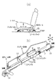
図1(a)に概略的に示すように、シートトラック1として、車体のフロア2には一対のロアレール3が固定されているとともに、シート4には一対のアッパレール5が固定され、両アッパレール5は、両ロアレール3に嵌入され、図2に示すガイドレール機構M(後で詳述)により移動可能に支持されている。
【0012】
図1(b)に概略的に示すように、一方のロアレール3において、ロアレール本体6の下側には複数のロック孔7(ロック部)がアッパレール5の移動方向A(前後方向)に沿って並設されている。
【0013】
一方のアッパレール5において、アッパレール本体8にはロックブラケット9とハンドルサポート10とが取着されている。このロックブラケット9には一対の軸支部9aが二股状に形成されている。このロックブラケット9の両軸支部9a及びハンドルサポート10にはハンドル11が回動可能に挿嵌されている。このハンドル11は、ロック位置とロック解除位置との間で回動し、ねじりコイルばね12の弾性力により常にロック位置で保持されている。
【0014】
ロックレバー13(ロック部材)は、前記ロックブラケット9の両軸支部9a間でハンドル11の外周に固着されてハンドル11とともに回動する。ロック状態では、このロックレバー13が前記ロアレール本体6のロック孔7に係入されるため、アッパレール本体8がロアレール本体6に対し移動不能になる。
【0015】
前記ハンドル11をねじりコイルばね12の弾性力に抗してロック位置からロック解除位置まで回動操作すると、ロックレバー13もロック解除位置になってロック孔7から抜ける。従って、ロック解除状態となり、アッパレール本体8をシート4とともにロアレール本体6に対し移動させることができる。シート4を位置決めした後、ハンドル11を離すと、ハンドル11がねじりコイルばね12の弾性力によりロック位置へ回動し、ロックレバー13もロック位置になってロック孔7に係入される。
【0016】
図1(b)に示すロアレール3において、ロアレール本体6の前後両端部下側には、それぞれ、前記ロアレール本体6をフロア2に固定するための前側ロアブラケット14及び後側ロアブラケット15が取着されている。
【0017】
前記ロアレール本体6に取着された前記前後両ロアブラケット14,15は、前記フロア2上に設けられたブラケット16に対し固定されている。
<図2に示す前記ガイドレール機構M>
このガイドレール機構Mは、前記ロアレール3の本体6に対しアッパレール5の本体8を移動可能に支持する一対のガイド17を前後両側に備えている。
【0018】
この前後両ガイド17の本体18は、前記ロアレール本体6の底壁19と前記アッパレール本体8の底壁20との間に介在された底壁21と、前記ロアレール本体6の左右両側壁22と前記アッパレール本体8の左右両側壁23との間に介在された左右両側壁24とを備えている。
【0019】
前記ガイド本体18の底壁21には、前記ロアレール本体6の底壁19及び前記アッパレール本体8の底壁20に支持される底壁受圧案内部25(後で詳述)が設けられている。前記ガイド本体18の左右両側壁24には、前記ロアレール本体6の左右両側壁22及び前記アッパレール本体8の左右両側壁23に支持される側壁受圧案内部26が設けられている。この左右両側壁受圧案内部26においては、前後両球体27が支持されている。
【0020】
<前記底壁受圧案内部25>
図2(a)に示す前側ガイド17の底壁受圧案内部25と、図2(b)に示す後側ガイド17の底壁受圧案内部25とにおいて、ガイド本体18の底壁21に開孔28が形成され、この開孔28にはころ29,30(転動体)が嵌め込まれている。このころ29,30は、開孔28の上下方向へ突出し、ロアレール本体6の底壁19及びアッパレール本体8の底壁20に当接して支持され、アッパレール5の移動方向Aへ転動するように回転する。
【0021】
ロアレール本体6の底壁19とアッパレール本体8の底壁20との間は、前後方向Aに対し直交する左右方向Bの両側で、図3にも概略的に示すように内側経路31と外側経路32とに区分されている。
【0022】
前記外側経路32でロアレール3のロアレール本体6には、前後方向Aで配設された前側ロアストッパ部33(前側前進ストッパ)及び中間ロアストッパ部34(前側後退ストッパ)と、前後方向Aで配設された前側アッパストッパ部35(前側後退ストッパ)及び中間アッパストッパ部36(前側前進ストッパ)とが突設されている。また、前記内側経路31でアッパレール5のアッパレール本体8には、前後方向Aで配設された中間ロアストッパ部37(後側前進ストッパ)及び後側ロアストッパ部38(後側後退ストッパ)と、前後方向Aで配設された中間アッパストッパ部39(後側後退ストッパ)及び後側アッパストッパ部40(後側前進ストッパ)とが突設されている。
【0023】
前側ガイド17のころ29は、前記外側経路32において、前側ロアストッパ部33と中間ロアストッパ部34との間、前側アッパストッパ部35と中間アッパストッパ部36との間で、前後方向Aへ移動する。この前側ころ29の移動範囲S29は、ロアレール3のロアレール本体6及びアッパレール5のアッパレール本体8における外側経路32にある。
【0024】
また、後側ガイド17のころ30は、前記内側経路31において、中間ロアストッパ部37と後側ロアストッパ部38との間、中間アッパストッパ部39と後側アッパストッパ部40との間で、前側ころ29に対し前後方向Aへ離間して移動する。この後側ころ30の移動範囲S30は、ロアレール3のロアレール本体6及びアッパレール5のアッパレール本体8における内側経路31にある。
【0025】
前側ロアストッパ部33と中間ロアストッパ部34との間の距離と、前側アッパストッパ部35と中間アッパストッパ部36との間の距離と、中間ロアストッパ部37と後側ロアストッパ部38との間の距離と、中間アッパストッパ部39と後側アッパストッパ部40との間の距離とは、それぞれ、互いに等しくなっている。そのため、外側経路32における中間ロアストッパ部34の位置と内側経路31における中間ロアストッパ部37の位置とが前後方向Aへ互いに離間するずれWを持つとともに、外側経路32における中間アッパストッパ部36の位置と内側経路31における中間アッパストッパ部39の位置とが前後方向Aへ互いに離間するずれWを持つ。それらのずれWにより、ロアレール3のロアレール本体6及びアッパレール5のアッパレール本体8においてそれぞれ、内側経路31の端部(ラップ部31a)と外側経路32の端部(ラップ部32a)とが左右方向Bの両側で並設された状態になる。
【0026】
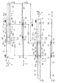
<図3(a)(b)に示すアッパレール5の最後退状態P>
この最後退状態Pでは、アッパレール5がロアレール3から後方へ突出し、前側ころ29が中間ロアストッパ部34と前側アッパストッパ部35とで挟まれた状態でそれらのストッパ部34,35に当接するとともに、後側ころ30が後側ロアストッパ部38と中間アッパストッパ部39とで挟まれた状態でそれらのストッパ部38,39に当接する。そのため、前側ころ29及び後側ころ30の後退が阻止され、ロアレール3に対するアッパレール5の後退も阻止される。
【0027】
<図3(c)(d)に示すアッパレール5の最前進状態Q>
この最前進状態Qでは、アッパレール5がロアレール3から前方へ突出し、前側ころ29が前側ロアストッパ部33と中間アッパストッパ部36とで挟まれた状態でそれらのストッパ部33,36に当接するとともに、後側ころ30が中間ロアストッパ部37と後側アッパストッパ部40とで挟まれた状態でそれらのストッパ部37,40に当接する。そのため、前側ころ29及び後側ころ30の前進が阻止され、ロアレール3に対するアッパレール5の前進も阻止される。
【0028】
<第一実施形態の特徴>
第一実施形態は下記の特徴(後記する他の技術的思想以外)を有する。
前述したように、外側経路32を通る前側ころ29と内側経路31を通る後側ころ30とに分け、アッパレール5の最前進状態Qで前側ころ29及び後側ころ30の前進を阻止するストッパ(前側ロアストッパ部33、中間アッパストッパ部36、中間ロアストッパ部37、後側アッパストッパ部40)と、アッパレール5の最後退状態Pで前側ころ29及び後側ころ30の後退を阻止するストッパ(中間ロアストッパ部34、前側アッパストッパ部35、後側ロアストッパ部38、中間アッパストッパ部39)とを設けた。そのため、アッパレール5の最後退状態Pにおける前側後退ストッパ(中間ロアストッパ部34、前側アッパストッパ部35)の位置と、アッパレール5の最前進状態Qにおける後側前進ストッパ(中間ロアストッパ部37、後側アッパストッパ部40)の位置とを前後方向Aへ互いに離間させたずれWを設定し、ロアレール3及びアッパレール5においてそれぞれ、内側経路31の端部(ラップ部31a)と外側経路32の端部(ラップ部32a)とを左右方向Bの平面上の両側で互いに離間して並設させることができる。すなわち、内側経路31と外側経路32とを左右方向Bの平面上の両側で互いに離間して並設し、アッパレール5の最後退状態Pとアッパレール5の最前進状態Qとの間で、外側経路32にある前側転動体29の移動範囲S29と、内側経路31にある後側転動体30の移動範囲S30とを左右方向Bで互いにラップさせることができる。従って、図3(a)(b)に示す最後退状態Pと図3(c)(d)に示す最前進状態Qとの間でなすアッパレール5の移動ストロークLについて、ロアレール3及びアッパレール5を延長させることなく、増大させることができる。
【0029】
〔第二実施形態〕
次に、本発明の第二実施形態にかかる車両用シートトラックスライド装置を図4〜5を参照して説明する。
【0030】
この第二実施形態では、第一実施形態において外側経路32を通る前側ころ29の形状と内側経路31を通る後側ころ30の形状とをそれぞれ変更した。この前側ころ29は、外側経路32を通って前側前進ストッパ(前側ロアストッパ部33、中間アッパストッパ部36)及び前側後退ストッパ(中間ロアストッパ部34、前側アッパストッパ部35)に当接し得る係止部29aと、内側経路31を通る案内部29bとからなる。この後側ころ30は、内側経路31を通って後側前進ストッパ(中間ロアストッパ部37、後側アッパストッパ部40)及び後側後退ストッパ(後側ロアストッパ部38、中間アッパストッパ部39)に当接し得る係止部30aと、外側経路32を通る案内部30bとからなる。さらに、この前側ころ29の案内部29bには、内側経路31を通る場合に中間ロアストッパ部37及び中間アッパストッパ部39との当接を回避する周溝状の回避部29cが設けられている。この後側ころ30の案内部30bには、外側経路32を通る場合に中間ロアストッパ部34及び中間アッパストッパ部36との当接を回避する周溝状の回避部30cが設けられている。
【0031】
このように、前側ころ29及び後側ころ30には係止部29a,30aのほかに案内部29b,30b及び回避部29c,30cを設けたので、前側ころ29及び後側ころ30の転動時に支持部分が広がってアッパレール5の安定性をより一層向上させることができる。
【0032】
〔他の実施形態〕
前記各実施形態以外にも下記*のように構成してもよい。
* 図示しないが、アッパレール5の前進を阻止する前進ストッパや、アッパレール5の後退を阻止する後退ストッパとしては、前述した前側前進ストッパ(前側ロアストッパ部33、中間アッパストッパ部36)や後側前進ストッパ(中間ロアストッパ部37、後側アッパストッパ部40)や前側後退ストッパ(中間ロアストッパ部34、前側アッパストッパ部35)や後側後退ストッパ(後側ロアストッパ部38、中間アッパストッパ部39)のほかに、アッパレール5に当接し得る別のストッパ手段をロアレール3等に設ける。この場合、前記ストッパ手段がアッパレール5の前進及び後退を阻止する機能を持ち、上記各ストッパ部33,34,35,36,37,38,39,40は前側ころ29及び後側ころ30の抜止め機能を果たす。
【0033】
* 図示しないが、内側経路31及び外側経路32を含む複数の経路に分けることも可能であり、その場合には転動体としてのころも各経路ごとに設ける。
* 図示しないが、ガイド17の底壁受圧案内部25において、転動体としてのころ29,30を球体に変更する。
【0034】
〔他の技術的思想〕
前記各実施形態から把握できる技術的思想(請求項以外)を記載する。
(イ) 請求項2または請求項3において、前側前進ストッパ及び前側後退ストッパは、それぞれ、前側転動体(前側ころ29)に当接し得るようにロアレール3に設けたロアストッパ部33,34とアッパレール5に設けたアッパストッパ部35,36とを有し、後側前進ストッパ及び後側後退ストッパは、それぞれ、後側転動体(後側ころ30)に当接し得るようにロアレール3に設けたロアストッパ部37,38とアッパレール5に設けたアッパストッパ部39,40とを有している。従って、前側前進ストッパ及び前側後退ストッパを簡単な構造のもとで形成することができる。
【0035】
(ロ) 請求項3において、内側経路31と外側経路32とのうち、一方の経路32で移動する前側転動体(前側ころ29)の案内部29bは、他方の経路31を通る場合に後側前進ストッパ(中間ロアストッパ部37)及び後側後退ストッパ(中間アッパストッパ部39)との当接を回避する回避部29cを有し、他方の経路31で移動する後側転動体(後側ころ30)の案内部30bは、一方の経路32を通る場合に前側後退ストッパ(中間ロアストッパ部34)及び前側前進ストッパ(中間アッパストッパ部36)との当接を回避する回避部30cを有している。従って、前側転動体(前側ころ29)及び後側転動体(後側ころ30)を円滑に移動させることができる。
【0036】
(ハ) 上記(イ)において、前側転動体(前側ころ29)及び後側転動体(後側ころ30)は、それぞれ、ロアストッパ部33,34,37,38とアッパストッパ部35,36,39,40とで挟まれた状態でそれらのストッパ部33,34,35,36,37,38,39,40に当接する。従って、前側転動体(前側ころ29)及び後側転動体(後側ころ30)の移動を確実に阻止することができる。
【0037】
(ニ) 上記(イ)または上記(ハ)において、内側経路31と外側経路32とのうち、前側転動体(前側ころ29)が移動する一方の経路32には、前後方向Aで配設された前側ロアストッパ部33及び中間ロアストッパ部34と、前後方向Aで配設された前側アッパストッパ部35及び中間アッパストッパ部36とを有し、後側転動体(後側ころ30)が移動する他方の経路31には、前後方向Aで配設された中間ロアストッパ部37及び後側ロアストッパ部38と、前後方向Aで配設された中間アッパストッパ部39及び後側アッパストッパ部40とを有し、一方の経路32における中間ロアストッパ部34の位置と他方の経路31における中間ロアストッパ部37の位置とが前後方向Aへ互いに離間するずれWを持つとともに、一方の経路31における中間アッパストッパ部36の位置と他方の経路31における中間アッパストッパ部39の位置とが前後方向Aへ互いに離間するずれWを持つ。従って、簡単な構造のもとでアッパレール5の移動ストロークLを増大させることができる。
【0038】
【発明の効果】
請求項1の発明にかかるシートトラックスライド装置のガイドレール機構(M)によれば、内側経路(31)と外側経路(32)とのうち一方の経路(32)を通る前側転動体(29)と他方の経路(31)を通る後側転動体(30)とに分けるとともに、アッパレール(5)の最後退状態(P)とアッパレール(5)の最前進状態(Q)との間で、一方の経路(32)にある前側転動体(29)の移動範囲(S29)と、他方の経路(31)にある後側転動体(30)の移動範囲(S30)とを左右方向(B)で互いに離間してラップさせたので、アッパレール(5)の移動ストローク(L)を増大させることができる。
請求項2の発明にかかるシートトラックスライド装置のガイドレール機構(M)によれば、内側経路(31)と外側経路(32)とのうち一方の経路(32)を通る前側転動体(29)と他方の経路(31)を通る後側転動体(30)とに分けるとともに、アッパレール(5)の最後退状態(P)における前側後退ストッパ(34,35)の位置と、アッパレール(5)の最前進状態(Q)における後側前進ストッパ(37,40)の位置との間で設定したずれ(W)により、内側経路(31)の端部と外側経路(32)の端部とがラップ部(31a,32a)により左右方向Bの両側で互いに離間して並設されるので、アッパレール(5)の移動ストローク(L)を増大させることができる。
【0039】
請求項3の発明によれば、請求項2の発明の効果に加え、前側転動体(29)及び後側転動体(30)には係止部(29a,30a)のほかに案内部(29b,30b)を設けたので、前側転動体(29)及び後側転動体(30)の転動時に支持部分が広がってアッパレール(5)の安定性をより一層向上させることができる。
【図面の簡単な説明】
【図1】 (a)は第一実施形態においてフロア上にシートをシートトラックを介して設置した状態を示す概略側面図であり、(b)は同じくシートトラックスライド装置を示す組付け斜視図である。
【図2】 図1(b)のシートトラックスライド装置においてガイドレール機構を示す部分断面図である。
【図3】 (a)は第一実施形態においてアッパレールの最後退状態を示す概略平面図であり、(b)は同じく概略側面図であり、(c)は第一実施形態においてアッパレールの最前進状態を示す概略平面図であり、(d)は同じく概略側面図である。
【図4】 第二実施形態にかかるシートトラックスライド装置においてガイドレール機構を示す部分断面図である。
【図5】 (a)は第二実施形態においてアッパレールの最後退状態を示す概略平面図であり、(b)は同じく概略側面図であり、(c)は第二実施形態においてアッパレールの最前進状態を示す概略平面図であり、(d)は同じく概略側面図である。
【図6】 従来のシートトラックスライド装置においてガイドレール機構を示す部分断面図である。
【図7】 (a)は従来においてアッパレールの最後退状態を示す概略平面図であり、(b)は同じく概略側面図であり、(c)は従来においてアッパレールの最前進状態を示す概略平面図であり、(d)は同じく概略側面図である。
【符号の説明】
1…シートトラック、2…フロア、3…ロアレール、4…シート、5…アッパレール、17…ガイド、29…前側ころ(前側転動体)、30…後側ころ(後側転動体)、29a,30a…係止部、29b,30b…案内部、29c,30c…回避部、31…内側経路、31a…ラップ部(内側経路端部)、32…外側経路、32a…ラップ部(外側経路端部)、33…前側ロアストッパ部(前側前進ストッパ)、34…中間ロアストッパ部(前側後退ストッパ)、35…前側アッパストッパ部(前側後退ストッパ)、36…中間アッパストッパ部(前側前進ストッパ)、37…中間ロアストッパ部(後退前進ストッパ)、38…後側ロアストッパ部(後側後退ストッパ)、39…中間アッパストッパ部(後側後退ストッパ)、40…後側アッパストッパ部(後側前進ストッパ)、Q…アッパレール最前進状態、P…アッパレール最後退状態、A…前後方向(アッパレール移動方向)、B…左右方向、M…ガイドレール機構、W…ずれ、L…アッパレール移動ストローク。[0001]
BACKGROUND OF THE INVENTION
The present invention relates to a guide rail mechanism provided with a guide for movably supporting an upper rail with respect to a lower rail in a vehicle seat track slide device.
[0002]
[Prior art]
As shown schematically in FIGS. 6 to 7, conventionally, in the
[0003]
[Problems to be solved by the invention]
The
[0004]
An object of the present invention is to increase the movement stroke of the upper rail without extending the lower rail and the upper rail.
[0005]
[Means for Solving the Problems]
The present invention will be described with reference to the drawings of the following embodiments (first embodiment shown in FIGS. 1 to 3 and second embodiment shown in FIGS. 4 to 5).
[0006]
The seat track slide device according to the invention of claim 1 corresponds to the first embodiment and the second embodiment, and is fixed to the lower rail (3) fixed to the floor (2) of the vehicle body and the seat (4). An upper rail (5) and a guide (17) for movably supporting the upper rail (5) with respect to the lower rail (3) are provided, and the upper rail (5) ) Can be in the most advanced state (Q) in which it projects forward from the lower rail (3), and it can be in the last retracted state (P) in which the upper rail (5) projects backward from the lower rail (3). The guide rail mechanism (M) in the seat track slide device is configured as follows.
[0007]
In the guide (17), one of the inner path (31) and the outer path (32) divided on both sides in the left-right direction (B) orthogonal to the front-rear direction (A) (32) ) And a rear rolling element (30) that moves away from the front rolling element (29) in the longitudinal direction (A) with respect to the front rolling element (29) in the other path (31). ). A forward stopper (33, 36, 37, 40) for preventing the upper rail (5) from moving forward and a backward stopper (34, 35, 38, 39) for preventing the upper rail (5) from retracting are provided. The inner path (31)WhenThe outer path (32) on both sides in the left-right direction (B)Away from each otherIt is installed side by side.
Between the last retracted state (P) of the upper rail (5) and the most advanced state (Q) of the upper rail (5), one of the inner route (31) and the outer route (32) (32) The moving range (S29) of the front rolling element (29) in the left and the moving range (S30) of the rear rolling element (30) in the other path (31) are overlapped in the left-right direction (B). .
[0008]
The seat track slide device according to the invention of
In the guide (17), one of the inner path (31) and the outer path (32) divided on both sides in the left-right direction (B) orthogonal to the front-rear direction (A) (32) ) And a rear rolling element (30) that moves away from the front rolling element (29) in the longitudinal direction (A) with respect to the front rolling element (29) in the other path (31). ).
Prevents advance of upper rail (5)The advance stoppers prevent the advance of the front rolling elements (29) and the front advance stoppers (33, 36) and the rear rolling elements (30) in the most advanced state (Q) of the upper rail (5). Rear advance stoppers (37, 40).Prevent retraction of the upper rail (5)The reverse stoppers prevent the front rolling stoppers (34, 35) and the rear rolling elements (30) from retreating in the last retracted state (P) of the upper rail (5). It is a rear side reverse stopper (38, 39). The position of the front reverse stopper (34, 35) in the last retracted state (P) of the upper rail (5) and the position of the rear advance stopper (37, 40) in the most advanced state (Q) of the upper rail (5) are: Set to have a deviation (W) that is separated from each other in the front-rear direction (A),Due to the shift (W), the end of the inner path (31) and the end of the outer path (32) are arranged side by side on both sides in the left-right direction (B) by the wrap portions (31a, 32a). .
[0009]
The invention of
Of the inner path (31) and the outer path (32), the front rolling element (29) moving in one path (32) passes through the one path (32) and the front advance stopper (33, 36) and In addition to the locking portion (29a) that can come into contact with the front retreat stopper (34, 35), contact with the rear advance stopper (37) and the rear retreat stopper (39) is avoided, and the other path (31 ) Through the guide part (29b). Of the inner path (31) and the outer path (32), the rear rolling element (30) moving in the other path (31) passes through the other path (31) and the rear advancement stopper (37, 40). ) And the locking portion (30a) that can come into contact with the rearward reverse stopper (38, 39), and avoiding contact with the frontward reverse stopper (34) and the front forward stopper (36), 32) having a guide portion (30b) passing through.
[0010]
DETAILED DESCRIPTION OF THE INVENTION
[First embodiment]
First, a vehicle seat track slide device according to a first embodiment of the present invention will be described with reference to FIGS.
[0011]
<Outline of vehicle seat track slide device>
As schematically shown in FIG. 1A, a pair of
[0012]
As schematically shown in FIG. 1B, in one
[0013]
In one
[0014]
The lock lever 13 (lock member) is fixed to the outer periphery of the handle 11 between the shaft support portions 9 a of the lock bracket 9 and rotates together with the handle 11. In the locked state, the lock lever 13 is engaged with the lock hole 7 of the
[0015]
When the handle 11 is rotated from the locked position to the unlocked position against the elastic force of the
[0016]
In the
[0017]
The front and rear
<The guide rail mechanism M shown in FIG. 2>
The guide rail mechanism M includes a pair of
[0018]
The
[0019]
The
[0020]
<The bottom wall pressure guide
The bottom wall pressure receiving
[0021]
Between the
[0022]
In the
[0023]
The
[0024]
Further, the
[0025]
A distance between the front
[0026]
<The last retracted state P of the
In this last retracted state P, the
[0027]
<The most advanced state Q of the
In this most advanced state Q, the
[0028]
<Characteristics of the first embodiment>
The first embodiment has the following features (other than other technical ideas described later).
As described above, the
[0029]
[Second Embodiment]
Next, a vehicle seat track slide apparatus according to a second embodiment of the present invention will be described with reference to FIGS.
[0030]
In the second embodiment, the shape of the
[0031]
As described above, the
[0032]
[Other Embodiments]
In addition to the above embodiments, the following * may be used.
* Although not shown, as the forward stopper for preventing the
[0033]
* Although not shown, it can be divided into a plurality of paths including the
* Although not shown, in the bottom wall pressure receiving
[0034]
[Other technical ideas]
A technical idea (other than claims) that can be grasped from each of the embodiments will be described.
(A) In
[0035]
(B) In
[0036]
(C) In (a) above, the front rolling elements (front rollers 29) and the rear rolling elements (rear rollers 30) are respectively provided with
[0037]
(D) In (i) or (c) above, one of the
[0038]
【The invention's effect】
Invention of Claim 1According to the guide rail mechanism (M) of the seat track slide device according to the present invention, the front rolling element (29) passing through one path (32) of the inner path (31) and the outer path (32) and the other path ( 31) divided into rear rolling elements (30) passing throughIn addition, the moving range (S29) of the front rolling element (29) on one path (32) between the most retracted state (P) of the upper rail (5) and the most advanced state (Q) of the upper rail (5). ) And the movement range (S30) of the rear rolling element (30) in the other path (31) are separated and wrapped in the left-right direction (B).The movement stroke (L) of the upper rail (5) can be increased.
According to the guide rail mechanism (M) of the seat track slide device according to the second aspect of the present invention, the front rolling element (29) passing through one of the inner path (31) and the outer path (32). And the rear rolling element (30) passing through the other path (31), the position of the front reverse stopper (34, 35) in the last retracted state (P) of the upper rail (5), and the upper rail (5) The end of the inner path (31) and the end of the outer path (32) are overlapped by the deviation (W) set between the position of the rear advance stopper (37, 40) in the most advanced state (Q). Since the portions (31a, 32a) are arranged side by side on both sides in the left-right direction B, the movement stroke (L) of the upper rail (5) can be increased.
[0039]
According to the invention of
[Brief description of the drawings]
FIG. 1A is a schematic side view showing a state in which a seat is installed on a floor via a seat track in the first embodiment, and FIG. 1B is an assembled perspective view showing a seat track slide device. is there.
FIG. 2 is a partial cross-sectional view showing a guide rail mechanism in the seat track sliding device of FIG.
3A is a schematic plan view showing a state in which the upper rail is finally retracted in the first embodiment, FIG. 3B is a schematic side view, and FIG. 3C is the most advanced state of the upper rail in the first embodiment. It is a schematic plan view which shows a state, (d) is a schematic side view similarly.
FIG. 4 is a partial cross-sectional view showing a guide rail mechanism in a seat track slide device according to a second embodiment.
5A is a schematic plan view showing a state in which the upper rail is finally retracted in the second embodiment, FIG. 5B is a schematic side view, and FIG. 5C is the most advanced state of the upper rail in the second embodiment. It is a schematic plan view which shows a state, (d) is a schematic side view similarly.
FIG. 6 is a partial cross-sectional view showing a guide rail mechanism in a conventional seat track sliding apparatus.
7A is a schematic plan view showing a state in which the upper rail is retracted in the prior art, FIG. 7B is a schematic side view, and FIG. 7C is a schematic plan view showing a state in which the upper rail is most advanced in the prior art. (D) is a schematic side view of the same.
[Explanation of symbols]
DESCRIPTION OF SYMBOLS 1 ... Seat track, 2 ... Floor, 3 ... Lower rail, 4 ... Seat, 5 ... Upper rail, 17 ... Guide, 29 ... Front side roller (front side rolling element), 30 ... Rear side roller (rear side rolling element), 29a, 30a ... Locking part, 29b, 30b ... Guide part, 29c, 30c ... Avoidance part, 31 ... Inner path, 31a ... Wrap part (inner path end part), 32 ... Outer path, 32a ... Wrap part (outer path end part) , 33 ... front lower stopper (front advance stopper), 34 intermediate lower stopper (front reverse stopper), 35 upper front stopper (front reverse stopper), 36 intermediate upper stopper (front advance stopper), 37 intermediate Lower stopper part (retracting forward stopper), 38 ... rear lower stopper part (rear backward stopper), 39 ... intermediate upper stopper part (rear backward stopper), 40 ... rear upper part Stopper part (rear advance stopper), Q ... Upper rail most advanced state, P ... Upper rail last retracted state, A ... Front / rear direction (upper rail movement direction), B ... Left / Right direction, M ... Guide rail mechanism, W ... Shift, L ... Upper rail travel stroke.
Claims (3)
前記ガイド(17)にあっては、前後方向(A)に対し直交する左右方向(B)の両側で区分された内側経路(31)と外側経路(32)とのうち、一方の経路(32)で前後方向(A)へ移動する前側転動体(29)と、他方の経路(31)において前側転動体(29)に対し前後方向(A)へ離間して移動する後側転動体(30)とを備え、
アッパレール(5)の前進を阻止する前進ストッパ(33,36,37,40)と、アッパレール(5)の後退を阻止する後退ストッパ(34,35,38,39)とを設け、
前記内側経路(31)と前記外側経路(32)とを前記左右方向(B)の両側で互いに離間して並設し、アッパレール(5)の最後退状態(P)とアッパレール(5)の最前進状態(Q)との間で、この内側経路(31)と外側経路(32)とのうち、一方の経路(32)にある前側転動体(29)の移動範囲(S29)と、他方の経路(31)にある後側転動体(30)の移動範囲(S30)とを左右方向(B)で互いにラップさせた
ことを特徴とするシートトラックスライド装置におけるガイドレール機構。A lower rail (3) fixed to the floor (2) of the vehicle body, an upper rail (5) fixed to the seat (4), and a guide (17) for supporting the upper rail (5) movably with respect to the lower rail (3) ), In the front-rear direction (A), which is the direction of movement of the upper rail (5), the upper rail (5) projects forward from the lower rail (3) and the upper rail (5) is lower rail (5). 3) In the seat track slide device capable of taking the last retracted state (P) protruding backward from
In the guide (17), one of the inner path (31) and the outer path (32) divided on both sides in the left-right direction (B) orthogonal to the front-rear direction (A) (32) ) And a rear rolling element (30) that moves away from the front rolling element (29) in the longitudinal direction (A) with respect to the front rolling element (29) in the other path (31). )
A forward stopper (33, 36, 37, 40) for preventing the upper rail (5) from moving forward, and a backward stopper (34, 35, 38, 39) for preventing the upper rail (5) from moving backward;
The inner path (31) and the outer path (32) are spaced apart from each other on both sides in the left-right direction (B), and the rearmost state (P) of the upper rail (5) and the upper rail (5) Between the forward state (Q), the movement range (S29) of the front rolling element (29) in one of the inner paths (31) and the outer path (32) and the other path (32). The guide rail mechanism in the seat track slide device, wherein the moving range (S30) of the rear rolling element (30) on the path (31) is overlapped with each other in the left-right direction (B) .
前記ガイド(17)にあっては、前後方向(A)に対し直交する左右方向(B)の両側で区分された内側経路(31)と外側経路(32)とのうち、一方の経路(32)で前後方向(A)へ移動する前側転動体(29)と、他方の経路(31)において前側転動体(29)に対し前後方向(A)へ離間して移動する後側転動体(30)とを備え、
アッパレール(5)の前進を阻止する前進ストッパは、アッパレール(5)の最前進状態(Q)で、前側転動体(29)の前進を阻止する前側前進ストッパ(33,36)と、後側転動体(30)の前進を阻止する後側前進ストッパ(37,40)であり、
アッパレール(5)の後退を阻止する後退ストッパは、アッパレール(5)の最後退状態(P)で、前側転動体(29)の後退を阻止する前側後退ストッパ(34,35)と、後側転動体(30)の後退を阻止する後側後退ストッパ(38,39)であり、
アッパレール(5)の最後退状態(P)における前側後退ストッパ(34,35)の位置と、アッパレール(5)の最前進状態(Q)における後側前進ストッパ(37,40)の位置とが、前後方向(A)へ互いに離間するずれ(W)を持つように設定して、そのずれ(W)により、内側経路(31)の端部と外側経路(32)の端部とがラップ部(31a,32a)により左右方向(B)の両側で互いに離間して並設される
ことを特徴とするシートトラックスライド装置におけるガイドレール機構。 A lower rail (3) fixed to the floor (2) of the vehicle body, an upper rail (5) fixed to the seat (4), and a guide (17) for supporting the upper rail (5) movably with respect to the lower rail (3) ), In the front-rear direction (A), which is the direction of movement of the upper rail (5), the upper rail (5) projects forward from the lower rail (3) and the upper rail (5) is lower rail (5). 3) In the seat track slide device capable of taking the last retracted state (P) protruding backward from
In the guide (17), one of the inner path (31) and the outer path (32) divided on both sides in the left-right direction (B) orthogonal to the front-rear direction (A) (32) ) And a rear rolling element (30) that moves away from the front rolling element (29) in the longitudinal direction (A) with respect to the front rolling element (29) in the other path (31). )
The forward stopper that prevents the upper rail (5) from moving forward is the most advanced state (Q) of the upper rail (5), and the front advance stopper (33, 36) that blocks the forward rolling element (29) from moving forward, A rear advance stopper (37, 40) for preventing the moving body (30) from moving forward;
The retraction stopper for preventing the upper rail (5) from retreating is the front retraction stopper (34, 35) for preventing the front rolling element (29) from retreating in the last retreat state (P) of the upper rail (5). A rear reverse stopper (38, 39) for preventing the moving body (30) from moving backward;
The position of the front reverse stopper (34, 35) in the last retracted state (P) of the upper rail (5) and the position of the rear advance stopper (37, 40) in the most advanced state (Q) of the upper rail (5) are: It is set so as to have a shift (W) that is separated from each other in the front-rear direction (A), and the shift (W) causes the end of the inner path (31) and the end of the outer path (32) to overlap with each other. 31a, 32a) by the lateral direction (B) the guide rail mechanism in the feature and be Resid over preparative track slide device <br/> be arranged apart from each other on both sides of.
内側経路(31)と外側経路(32)とのうち、他方の経路(31)で移動する後側転動体(30)は、他方の経路(31)を通って後側前進ストッパ(37,40)及び後側後退ストッパ(38,39)に当接し得る係止部(30a)のほかに、前側後退ストッパ(34)及び前側前進ストッパ(36)との当接を回避して一方の経路(32)を通る案内部(30b)を有する
ことを特徴とする請求項2に記載のシートトラックスライド装置におけるガイドレール機構。Of the inner path (31) and the outer path (32), the front rolling element (29) moving in one path (32) passes through the one path (32) and the front advance stopper (33, 36) and In addition to the locking portion (29a) that can come into contact with the front retreat stopper (34, 35), contact with the rear advance stopper (37) and the rear retreat stopper (39) is avoided, and the other path (31 ) Through the guide (29b)
Of the inner path (31) and the outer path (32), the rear rolling element (30) moving in the other path (31) passes through the other path (31) and the rear advancement stopper (37, 40). ) And the locking portion (30a) that can come into contact with the rearward reverse stopper (38, 39), and avoiding contact with the frontward reverse stopper (34) and the front forward stopper (36), 32. The guide rail mechanism in the seat track slide device according to claim 2, further comprising a guide portion (30b) passing through 32).
Priority Applications (1)
| Application Number | Priority Date | Filing Date | Title |
|---|---|---|---|
| JP24181499A JP4237888B2 (en) | 1999-08-27 | 1999-08-27 | Guide rail mechanism in seat track slide device |
Applications Claiming Priority (1)
| Application Number | Priority Date | Filing Date | Title |
|---|---|---|---|
| JP24181499A JP4237888B2 (en) | 1999-08-27 | 1999-08-27 | Guide rail mechanism in seat track slide device |
Publications (3)
| Publication Number | Publication Date |
|---|---|
| JP2001063409A JP2001063409A (en) | 2001-03-13 |
| JP2001063409A5 JP2001063409A5 (en) | 2006-10-05 |
| JP4237888B2 true JP4237888B2 (en) | 2009-03-11 |
Family
ID=17079905
Family Applications (1)
| Application Number | Title | Priority Date | Filing Date |
|---|---|---|---|
| JP24181499A Expired - Fee Related JP4237888B2 (en) | 1999-08-27 | 1999-08-27 | Guide rail mechanism in seat track slide device |
Country Status (1)
| Country | Link |
|---|---|
| JP (1) | JP4237888B2 (en) |
Families Citing this family (1)
| Publication number | Priority date | Publication date | Assignee | Title |
|---|---|---|---|---|
| JP5516590B2 (en) * | 2009-09-10 | 2014-06-11 | トヨタ自動車株式会社 | Vehicle seat |
-
1999
- 1999-08-27 JP JP24181499A patent/JP4237888B2/en not_active Expired - Fee Related
Also Published As
| Publication number | Publication date |
|---|---|
| JP2001063409A (en) | 2001-03-13 |
Similar Documents
| Publication | Publication Date | Title |
|---|---|---|
| JP5889551B2 (en) | baby carriage | |
| US9120400B2 (en) | Positively engaged locking mechanism for a vehicle seat | |
| KR101194914B1 (en) | Mono leg transformer seat | |
| US7850242B2 (en) | Vehicle seats | |
| JP3670610B2 (en) | Cover device for automobile trunk room | |
| CN103562002A (en) | Vehicle seat | |
| CN102343838A (en) | Seat slide apparatus for vehicle | |
| JP2006008028A (en) | Vehicle seat device | |
| JP5795397B2 (en) | Electric manual release sheet | |
| JP4237888B2 (en) | Guide rail mechanism in seat track slide device | |
| CN109890656B (en) | Headrest moving device | |
| US20200238871A1 (en) | Headrest | |
| JP3696709B2 (en) | Automotive seat | |
| KR102001505B1 (en) | Seat rail for vehicle | |
| KR101805410B1 (en) | Single Memory Easy Entry System | |
| JP7283340B2 (en) | small electric vehicle | |
| JP2008285098A (en) | Seat slide device for vehicle | |
| JP7235945B2 (en) | seat rail device | |
| KR102586269B1 (en) | Locking apparatus of seat rail for vehicle | |
| US7000991B2 (en) | Vehicular seat | |
| JP4500934B2 (en) | Seat rotating slide device | |
| JP3216555B2 (en) | Vehicle seat slide device | |
| KR100507306B1 (en) | Long-Slide Locking Structure of Seat for Automobile | |
| JP3815390B2 (en) | Vehicle seat | |
| JP3811792B2 (en) | Seat walk-in device |
Legal Events
| Date | Code | Title | Description |
|---|---|---|---|
| A521 | Written amendment |
Free format text: JAPANESE INTERMEDIATE CODE: A523 Effective date: 20060823 |
|
| A621 | Written request for application examination |
Free format text: JAPANESE INTERMEDIATE CODE: A621 Effective date: 20060823 |
|
| A977 | Report on retrieval |
Free format text: JAPANESE INTERMEDIATE CODE: A971007 Effective date: 20080912 |
|
| A131 | Notification of reasons for refusal |
Free format text: JAPANESE INTERMEDIATE CODE: A131 Effective date: 20080924 |
|
| A521 | Written amendment |
Free format text: JAPANESE INTERMEDIATE CODE: A523 Effective date: 20081105 |
|
| TRDD | Decision of grant or rejection written | ||
| A01 | Written decision to grant a patent or to grant a registration (utility model) |
Free format text: JAPANESE INTERMEDIATE CODE: A01 Effective date: 20081202 |
|
| A01 | Written decision to grant a patent or to grant a registration (utility model) |
Free format text: JAPANESE INTERMEDIATE CODE: A01 |
|
| A61 | First payment of annual fees (during grant procedure) |
Free format text: JAPANESE INTERMEDIATE CODE: A61 Effective date: 20081219 |
|
| R150 | Certificate of patent or registration of utility model |
Free format text: JAPANESE INTERMEDIATE CODE: R150 |
|
| FPAY | Renewal fee payment (event date is renewal date of database) |
Free format text: PAYMENT UNTIL: 20111226 Year of fee payment: 3 |
|
| FPAY | Renewal fee payment (event date is renewal date of database) |
Free format text: PAYMENT UNTIL: 20141226 Year of fee payment: 6 |
|
| LAPS | Cancellation because of no payment of annual fees | ||
| S111 | Request for change of ownership or part of ownership |
Free format text: JAPANESE INTERMEDIATE CODE: R313113 |
|
| R360 | Written notification for declining of transfer of rights |
Free format text: JAPANESE INTERMEDIATE CODE: R360 |
|
| R360 | Written notification for declining of transfer of rights |
Free format text: JAPANESE INTERMEDIATE CODE: R360 |
|
| R371 | Transfer withdrawn |
Free format text: JAPANESE INTERMEDIATE CODE: R371 |