JP4237690B2 - Pneumatic tire - Google Patents
Pneumatic tire Download PDFInfo
- Publication number
- JP4237690B2 JP4237690B2 JP2004312753A JP2004312753A JP4237690B2 JP 4237690 B2 JP4237690 B2 JP 4237690B2 JP 2004312753 A JP2004312753 A JP 2004312753A JP 2004312753 A JP2004312753 A JP 2004312753A JP 4237690 B2 JP4237690 B2 JP 4237690B2
- Authority
- JP
- Japan
- Prior art keywords
- zigzag
- siping
- displacement
- length direction
- block
- Prior art date
- Legal status (The legal status is an assumption and is not a legal conclusion. Google has not performed a legal analysis and makes no representation as to the accuracy of the status listed.)
- Active
Links
Images


Classifications
-
- B—PERFORMING OPERATIONS; TRANSPORTING
- B60—VEHICLES IN GENERAL
- B60C—VEHICLE TYRES; TYRE INFLATION; TYRE CHANGING; CONNECTING VALVES TO INFLATABLE ELASTIC BODIES IN GENERAL; DEVICES OR ARRANGEMENTS RELATED TO TYRES
- B60C11/00—Tyre tread bands; Tread patterns; Anti-skid inserts
- B60C11/03—Tread patterns
- B60C11/0306—Patterns comprising block rows or discontinuous ribs
-
- B—PERFORMING OPERATIONS; TRANSPORTING
- B60—VEHICLES IN GENERAL
- B60C—VEHICLE TYRES; TYRE INFLATION; TYRE CHANGING; CONNECTING VALVES TO INFLATABLE ELASTIC BODIES IN GENERAL; DEVICES OR ARRANGEMENTS RELATED TO TYRES
- B60C11/00—Tyre tread bands; Tread patterns; Anti-skid inserts
- B60C11/03—Tread patterns
- B60C11/12—Tread patterns characterised by the use of narrow slits or incisions, e.g. sipes
- B60C11/1204—Tread patterns characterised by the use of narrow slits or incisions, e.g. sipes with special shape of the sipe
- B60C11/1218—Three-dimensional shape with regard to depth and extending direction
-
- B—PERFORMING OPERATIONS; TRANSPORTING
- B29—WORKING OF PLASTICS; WORKING OF SUBSTANCES IN A PLASTIC STATE IN GENERAL
- B29D—PRODUCING PARTICULAR ARTICLES FROM PLASTICS OR FROM SUBSTANCES IN A PLASTIC STATE
- B29D30/00—Producing pneumatic or solid tyres or parts thereof
- B29D30/06—Pneumatic tyres or parts thereof (e.g. produced by casting, moulding, compression moulding, injection moulding, centrifugal casting)
- B29D30/0601—Vulcanising tyres; Vulcanising presses for tyres
- B29D30/0606—Vulcanising moulds not integral with vulcanising presses
- B29D2030/0607—Constructional features of the moulds
- B29D2030/0613—Means, e.g. sipes or blade-like elements, for forming narrow recesses in the tyres, e.g. cuts or incisions for winter tyres
-
- B—PERFORMING OPERATIONS; TRANSPORTING
- B60—VEHICLES IN GENERAL
- B60C—VEHICLE TYRES; TYRE INFLATION; TYRE CHANGING; CONNECTING VALVES TO INFLATABLE ELASTIC BODIES IN GENERAL; DEVICES OR ARRANGEMENTS RELATED TO TYRES
- B60C11/00—Tyre tread bands; Tread patterns; Anti-skid inserts
- B60C11/03—Tread patterns
- B60C11/12—Tread patterns characterised by the use of narrow slits or incisions, e.g. sipes
- B60C11/1204—Tread patterns characterised by the use of narrow slits or incisions, e.g. sipes with special shape of the sipe
- B60C2011/1213—Tread patterns characterised by the use of narrow slits or incisions, e.g. sipes with special shape of the sipe sinusoidal or zigzag at the tread surface
-
- Y—GENERAL TAGGING OF NEW TECHNOLOGICAL DEVELOPMENTS; GENERAL TAGGING OF CROSS-SECTIONAL TECHNOLOGIES SPANNING OVER SEVERAL SECTIONS OF THE IPC; TECHNICAL SUBJECTS COVERED BY FORMER USPC CROSS-REFERENCE ART COLLECTIONS [XRACs] AND DIGESTS
- Y10—TECHNICAL SUBJECTS COVERED BY FORMER USPC
- Y10S—TECHNICAL SUBJECTS COVERED BY FORMER USPC CROSS-REFERENCE ART COLLECTIONS [XRACs] AND DIGESTS
- Y10S152/00—Resilient tires and wheels
- Y10S152/03—Slits in threads
-
- Y—GENERAL TAGGING OF NEW TECHNOLOGICAL DEVELOPMENTS; GENERAL TAGGING OF CROSS-SECTIONAL TECHNOLOGIES SPANNING OVER SEVERAL SECTIONS OF THE IPC; TECHNICAL SUBJECTS COVERED BY FORMER USPC CROSS-REFERENCE ART COLLECTIONS [XRACs] AND DIGESTS
- Y10—TECHNICAL SUBJECTS COVERED BY FORMER USPC
- Y10S—TECHNICAL SUBJECTS COVERED BY FORMER USPC CROSS-REFERENCE ART COLLECTIONS [XRACs] AND DIGESTS
- Y10S152/00—Resilient tires and wheels
- Y10S152/902—Non-directional tread pattern having no circumferential rib and having blocks defined by circumferential grooves and transverse grooves
Description
本発明は、氷雪路面での走行に適したスタッドレスタイヤとして好適であり、ブロックに複数のサイピングを並設した空気入りタイヤに関する。 The present invention relates to a pneumatic tire that is suitable as a studless tire suitable for traveling on an icy and snowy road surface, and in which a plurality of sipings are arranged in parallel on a block.
空気入りタイヤにおいては、氷雪路面での走行性を向上させるため、トレッド部に設けたブロックに多数のサイピングを形成し、そのエッジによる路面引っ掻き力(エッジ効果)を増大させることが有効と考えられている。しかし、サイピングの形成数を増加させると、ブロックに大きな倒れ込みが生じてエッジ効果が有効に機能しなくなるなど、氷上性能の向上に限界をもたらしている。 In pneumatic tires, it is considered effective to increase the road surface scratching force (edge effect) by forming a large number of sipings on the block provided in the tread part in order to improve the running performance on icy and snowy road surfaces. ing. However, when the number of sipings formed is increased, there is a limit in improving the performance on ice, for example, a large collapse occurs in the block and the edge effect does not function effectively.
そこで本出願人は、このようなブロックの過度の倒れ込みを防止すべく、図9に示す如き構造(便宜上、三浦折り構造という)のサイピングを、特許文献1において提案している。 Therefore, the present applicant has proposed a siping having a structure as shown in FIG. 9 (referred to as a “Miura folding structure” for the sake of convenience) in order to prevent such an excessive collapse of the block.
この三浦折り構造のサイピングaは、ブロック表面で開口するサイピングaの開口縁形状bがジグザグ部b1を有するとともに、前記ブロック表面からサイピング底に向かうに従い、前記ジグザグ部b1が、そのジグザグ形状を維持しながらサイピングの長さ方向の一方側、他方側に変位するものである。このようなサイピングaは、その壁面cが、平行四辺形を組み合わせた3次元的凹凸の立体曲面をなし、向き合う壁面の凹凸が互いに噛み合うことにより、ブロックの倒れ込みを効果的に防止しうる。 In the siping a having the Miura fold structure, the opening edge shape b of the siping a that opens on the block surface has a zigzag portion b1, and the zigzag portion b1 maintains its zigzag shape as it goes from the block surface to the bottom of the siping. However, it is displaced to one side and the other side in the length direction of the siping. In such a siping a, the wall surface c forms a three-dimensional uneven surface with a combination of parallelograms, and the recesses and protrusions of the facing wall surfaces mesh with each other, thereby effectively preventing the block from falling down.
しかも前記サイピングaは、各深さ位置においてジグザグ形状が同一であるため、タイヤ加硫金型におけるサイピング形成用ナイフブレードのタイヤからの抜けがある程度容易であり、タイヤの製造効率の低下を抑えうるとともに、ナイフブレードの曲がり等の損傷抑制にも貢献できる。 Moreover, since the siping a has the same zigzag shape at each depth position, it is easy to remove the siping forming knife blade from the tire in the tire vulcanization mold to some extent, and it is possible to suppress a decrease in tire manufacturing efficiency. At the same time, it can contribute to suppression of damage such as bending of the knife blade.
本発明者は、このような利点をさらに向上させるべく、前記三浦折り構造のサイピングにおいて、サイピングの長さ方向の変位量、及び長さ方向と直角方向の変位量が、ブロック剛性、及びナイフブレードの抜け性や曲がり等にどの様な影響を与えるかにつき鋭意解析をすることにより、本件発明を完成した。 In order to further improve such advantages, the present inventor, in the siping of the Miura fold structure, the displacement amount in the longitudinal direction of the siping and the displacement amount in the direction perpendicular to the longitudinal direction are the block rigidity and the knife blade. The present invention has been completed by earnestly analyzing how it affects the looseness and bending of the sheet.
すなわち本発明は、前記三浦折り構造のサイピングの改良に係わり、ブロック倒れ込みの抑制効果を高く確保しながら、ナイフブレードのタイヤからの抜けをさらに円滑化することができ、タイヤの製造効率を高めるとともに、ナイフブレードへの曲げや損傷の抑制効果をより向上しうる空気入りタイヤを提供することを目的としている。 That is, the present invention relates to an improvement in the siping of the Miura fold structure, and while ensuring a high effect of suppressing the block collapse, it is possible to further facilitate the removal of the knife blade from the tire and to increase the manufacturing efficiency of the tire. An object of the present invention is to provide a pneumatic tire that can further improve the effect of suppressing bending and damage to a knife blade.
本発明のうち請求項1記載の発明は、トレッド溝により区画され、かつ複数のサイピングが並設されたブロックを有する空気入りタイヤであって、
前記サイピングは、ブロック表面で開口する開口縁形状において、山谷を繰り返してジグザグ状にのびるジグザグ部を有し、かつサイピングの深さ方向においては、前記開口縁形状を実質的に保持しつつ、前記ジグザグ部がサイピングの長さ方向の一端側に変位するジグザグ変位部と、他端側に変位するジグザグ変位部とが交互に繰り返すとともに、
ブロック表面側のジグザグ変位部の前記長さ方向と直角方向の変位量をW1、サイピング底側のジグザグ変位部の前記長さ方向と直角方向の変位量をW3、及びその間に配される中間のジグザグ変位部の前記長さ方向と直角方向の変位量をW2としたとき、次式を充足することを特徴としている。
W1≧W2
0.7×W2≧W3>0
The invention according to claim 1 of the present invention is a pneumatic tire having a block partitioned by a tread groove and provided with a plurality of sipings arranged in parallel,
The siping has a zigzag portion that repeats peaks and valleys in an opening edge shape that opens on the block surface, and extends substantially in the depth direction of the siping while substantially maintaining the opening edge shape. A zigzag displacement portion in which the zigzag portion is displaced to one end side in the length direction of the siping and a zigzag displacement portion to be displaced to the other end side are alternately repeated,
The displacement amount in the direction perpendicular to the length direction of the zigzag displacement portion on the block surface side is W1, the displacement amount in the direction perpendicular to the length direction of the zigzag displacement portion on the siping bottom side is W3, and the intermediate amount disposed therebetween When the amount of displacement of the zigzag displacement portion in the direction perpendicular to the length direction is W2, the following equation is satisfied.
W1 ≧ W2
0.7 × W2 ≧ W3> 0
又請求項の発明では、前記サイピングは、前記表面側のジグザグ変位部の前記長さ方向の変位量をL1、前記中間のジグザグ変位部の前記長さ方向の変位量をL2、及び前記サイピング底側のジグザグ変位部の前記長さ方向の変位量をL3としたとき、次式を充足することを特徴としている。
L1≧L2
0.7×L2≧L3>0
In the invention of claim 1, the siping includes a displacement amount in the length direction of the zigzag displacement portion on the surface side as L1, a displacement amount in the length direction of the intermediate zigzag displacement portion as L2, and the siping bottom. When the displacement amount in the length direction of the zigzag displacement portion on the side is L3, the following equation is satisfied.
L1 ≧ L2
0.7 × L2 ≧ L3> 0
又請求項3の発明では、前記サイピングは、前記長さ方向と直交する垂直断面において、ブロック表面での上点と、サイピング底での下点との間の、前記長さ方向と直角方向の距離Waを、前記変位量W1の70%以下としたことを特徴としている。 According to a third aspect of the present invention, the siping is perpendicular to the longitudinal direction between the upper point on the block surface and the lower point on the siping bottom in a vertical cross section orthogonal to the length direction. The distance Wa is 70% or less of the displacement amount W1.
又請求項4の発明では、前記サイピングは、各ジグザグ変位部の前記深さ方向の距離Kが互いに等しいことを特徴としている。
In the invention of
叙上の如く本発明は構成しているため、ブロック倒れ込みの抑制効果を高く確保しながら、ナイフブレードのタイヤからの抜けをさらに円滑化することができ、タイヤの製造効率を高めるとともに、ナイフブレードへの曲げや損傷の抑制効果をより向上しうる。 As described above, since the present invention is configured, it is possible to further facilitate the removal of the knife blade from the tire while ensuring a high effect of suppressing the block collapse. The effect of suppressing bending and damage can be further improved.
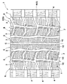
以下、本発明の実施の一形態を、図示例とともに説明する。図1は、本発明の空気入りタイヤが、乗用車用のスタッドレスタイヤである場合のトレッドパターンを説明する展開図である。 Hereinafter, an embodiment of the present invention will be described with reference to the drawings. FIG. 1 is a development view illustrating a tread pattern when the pneumatic tire of the present invention is a studless tire for a passenger car.
図1において、空気入りタイヤ1は、トレッド部2に、タイヤ周方向にのびる複数本の縦主溝3と、この縦主溝3と交わる向きにのびる横主溝4とからなるトレッド溝5を具え、これにより、トレッド部2を、タイヤ赤道Cを挟む例えば2本のリブ6、6と、その両外側に形成されかつブロック7がタイヤ周方向に隔置される例えば各2本のブロック列8とに区画している。なおトレッドパターンとしては、本例の如きリブ・ブロックパターンの他、ブロックパターンであっても良い。トレッド溝5としては、排水性能を向上するために溝幅を3.5mm以上とするのが好ましい。
In FIG. 1, a pneumatic tire 1 has a
そして前記ブロック7は、トレッド面であるブロック表面Sに複数のサイピング10を並設したサイピング付きブロックを含んで構成される。本例では、ブロック7の全てがサイピング付きブロックからなるものを例示しており、又前記リブ6にも複数のサイピング10を並設している。
The
前記サイピング10は、図2(A)に示すように、ブロック表面Sで開口する開口縁形状Jにおいて、ブロック表面S上の基準線Xを挟んで山谷を繰り返してジグザグ状にのびるジグザグ部11を有する。前記基準線Xは、ジグザグの振幅中心であって、氷路面での駆動、制動力の向上の観点から、該基準線Xのタイヤ軸方向に対する角度θを20°以下に設定するのが好ましい。本例では、前記基準線Xが直線状をなす好ましい場合を例示しているが、図2(B)の如く、円弧状の曲線であっても良く、係る場合には、前記基準線Xのうち、ジグザグ部11を通る線分の両端を結ぶ直線のタイヤ軸方向に対する角度θを20°以下とする。
As shown in FIG. 2 (A), the
又サイピング10が「並設」されるとは、前記基準線Xが互いに平行に配される、或いは隣合う基準線X、X間の角度が5°以下の略平行な状態を含む。又サイピング10として、本例では、ジグザグ部11の一端側、他端側に、基準線Xに沿って直線状(基準線X自体が円弧状の場合は円弧状)にのびる延長部13を縁設したものを例示しているが、この延長部13は要求により排除できる。又サイピング10として、その両端がブロック7のタイヤ軸方向側壁で開口する両側オープンタイプのものを例示しているが、一方のみが開口する片側オープンタイプであっても良く、又双方を閉口させたクローズタイプであっても良い。
Moreover, the simplification of the
又前記ジグザグ部11のジグザグ形状としては、本例の如く、直線を用いた例えば鋸歯状等の折れ線状のもの、或いは曲線を用いた例えば正弦波状等の波線状のものが採用しうる。しかし、ブロック剛性の観点、及びタイヤ加硫金型におけるサイピング形成用ナイフブレードの曲げ剛性を大きく確保する等の観点から、ジグザグ形状として折れ線状のものを採用し、かつその折れ曲がりのコーナを小円弧とするのが好ましい。
As the zigzag shape of the
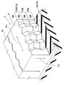
次に、図3にサイピング10の壁面14の斜視図を、又図4に壁面14の平面図及び正面図を示す。図3,4に示すように、前記サイピング10は、その深さ方向Ffにおいては、前記ジグザグ部11のジグザグ形状を実質的に保持しつつ、前記ジグザグ部11が長さ方向Fnの一端側に変位するジグザグ変位部15Aと、他端側に変位するジグザグ変位部15Bとを交互に繰り返して形成される。
Next, FIG. 3 shows a perspective view of the
言い換えると、図5に、前記図3、4の各深さ位置Q1〜Q4におけるブロック表面Sと平行な面でのサイピング形状を略示するように、ジグザグ部11のジグザグ形状は、各深さ位置Q1〜Q4において同一であり、かつジグザグ部11は、ブロック表面Sからの深さが増すにつれて、長さ方向Fnの一方側/他方側に変位が変化する。前記ジグザグ変位部15A,15Bを総称するとき、ジグザグ変位部15という。このときジグザグ部11の長さ方向Fnへの変位の割合は、各ジグザグ変位部15内では一定であり、従って、各ジグザグ変位部15内においては、ジグザグ部11の山/谷の稜線Pa、Pbは、互いに平行な傾斜直線として現れる。
In other words, in FIG. 5, the zigzag shape of the
又サイピング10は、ブロック表面S側となる最も上方のジグザグ変位部15Uと、サイピング底Bo側となる最も下方のジグザグ変位部15Lと、その間に配される1つ以上の中間のジグザグ変位部15Mとからなる合計3つ以上のジグザグ変位部15によって構成される。
The
このように構成する前記サイピング10は、前記図3の如く、壁面14が3次元的な凹凸を有する立体曲面として形成される。従って、対向する壁面14、14が、凹部と凸部とで互いに噛み合って支え合い、ブロック7の倒れ込みを効果的に抑制できる。その結果、接地面積の減少に伴う粘着摩擦力の低下を抑えうるとともに、エッジによる路面引っ掻き力(エッジ効果)が強くなり、氷上性能を向上しうる。
The
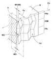
そして本発明では、図6、7図に示すように、前記ブロック表面S側のジグザグ変位部15Uの前記長さ方向Fnと直角方向Fv(便宜上、以下に振幅方向Fvという)の変位量をW1、サイピング底Bo側のジグザグ変位部15Lの前記振幅方向Fvの変位量をW3、及び前記中間のジグザグ変位部15Mの前記振幅方向Fvの変位量をW2としたとき、次式(1)、(2)を充足している。
W1≧W2 −−−−(1)
0.7×W2≧W3>0 −−−−(2)
In the present invention, as shown in FIGS. 6 and 7, the displacement amount of the
W1 ≧ W2 ---- (1)
0.7 × W2 ≧ W3> 0 ---- (2)
なお前記振幅方向Fvの変位量Wとは、前記図4の如く、ブロック表面Sにおけるジグザグ部11の山の頂点又は谷の底点(本例では山の頂点)を通り、前記長さ方向Fnと直交する垂直断面T(ブロック表面Sと直角)における、各ジグザグ変位部15U、15M、15Lの振幅方向Fvの変位量Wで定義される。又「変位量W2」は、前記中間のジグザグ変位部15Mが複数ある場合には、各中間のジグザグ変位部15Mの変位量Wの平均値を採用する。
The displacement amount W in the amplitude direction Fv is, as shown in FIG. 4, passing through the peak of the
前記式(1)、(2)が意味するところは、サイピング底Boに近いジグザグ変位部15ほど、振幅方向Fvの変位量Wが小さく、しかも最も下方のジグザグ変位部15Lの変位量W3は、中間のジグザグ変位部15Mの変位量W2の0.7倍以下とすることである。
The expressions (1) and (2) mean that the
ここで、サイピング底Bo側のジグザグ変位部15Lにおいては、ブロック7に外力が作用した際のサイピング壁面14同士の接触圧が、他のジグザグ変位部15U、15Mに比して著しく低く、変位量Wの大小に係わらず、ブロック倒れ込み抑制への寄与率が小さい。一方、このサイピング底Bo側のジグザグ変位部15Lは、トレッド補強コード層(例えばバンド層、ベルト層)やトレッドベースゴム層など剛性の高い部分に近く、かつブロック表面Sからの距離が大であることから、サイピング形成用ナイフブレードのタイヤからの抜き取り性や曲げ性等に与える影響が大きい。従って、ジグザグ変位部15U〜15Lにおいて、前記式(1)、(2)を充足させることにより、ブロック倒れ込み抑制効果を最大限に発揮しながら、ナイフブレードのタイヤからの抜き取りをより円滑化でき、タイヤの製造効率を高めるとともに、ナイフブレードへの曲げや損傷を効果的に抑制しうる。なお最も下方のジグザグ変位部15Lの変位量W3を0とすると、中間のジグザグ変位部15Mにおけるブロック倒れ込み抑制効果が低下する場合があり、W3は0以上、好ましくは0より大、さらに好ましくはW2の5%以上である。
Here, in the
上記作用効果を発揮するために、前記ジグザグ変位部15を、少なくとも3つ以上、例えば3〜5つ形成する。又上記作用効果をより高めるためには、前記変位量W1を変位量W2より大、さらには変位量W2は変位量W1の70%以上とするのが好ましく、特には80%以上、最も好ましくは90%以上とする。又前記変位量W3を、前記変位量W2の50%以下、さらには20%以下とするのも好ましい。又中間のジグザグ変位部15Mが複数ある場合には、深さ方向Ffに隣り合う2つの中間のジグザグ変位部15Mにおいて、浅い側を15Ma、深い側を15Mbとしたときの各変位量W2a、W2bを、W2a≧W2bとするのが好ましい。なお変位量W1自体の寸法は特に規制されないが、乗用車用タイヤの場合1.0〜1.8mmが一般的である。
In order to exert the above-described effects, at least three
次に、前記振幅方向Fvの変位量Wの変化は、ジグザグ変位部15の長さ方向Fnの変位量Lを変化させることによって達成できる。即ち本例では、前記表面側のジグザグ変位部15Uの前記長さ方向Fnの変位量をL1、中間のジグザグ変位部15Mの前記長さ方向Fnの変位量をL2、サイピング底側のジグザグ変位部15Lの前記長さ方向Fnの変位量をL3としたとき、次式(3)、(4)を充足させている。
L1≧L2 −−−−(3)
0.7×L2≧L3>0 −−−−(4)
Next, the change in the displacement amount W in the amplitude direction Fv can be achieved by changing the displacement amount L in the length direction Fn of the
L1 ≧ L2 ---- (3)
0.7 × L2 ≧ L3> 0 ---- (4)
これにより、前記(1)、(2)とすることができる。なお変位量L1を変位量L2より大、さらには変位量L2は変位量L1の70%以上とするのが好ましく、特には80%以上、最も好ましくは90%以上とする。又前記変位量L3を、前記変位量L2の50%以下、さらには20%以下とするのも好ましい。さらに変位量L3は、変位量L2の5%以上であることが好ましい。なお変位量L2は、変位量W2と同様、中間のジグザグ変位部15Mが複数ある場合には、各中間のジグザグ変位部15Mの変位量Lの平均値を採用する。
Thereby, it can be set as said (1) and (2). The displacement amount L1 is larger than the displacement amount L2, and the displacement amount L2 is preferably 70% or more, particularly 80% or more, and most preferably 90% or more of the displacement amount L1 . The displacement L3 is preferably 50% or less, more preferably 20% or less of the displacement L2. Furthermore, the displacement amount L3 is preferably 5% or more of the displacement amount L2. Similarly to the displacement amount W2, when there are a plurality of intermediate
又サイピング10では、前記図6,7の如く、ブロック表面Sにおけるジグザグ部11の山の頂点又は谷の底点(本例では山の頂点)を通り、前記長さ方向Fnと直交する垂直断面T(ブロック表面Sと直角)において、ブロック表面Sでの上点j1と、サイピング底Boでの下点j2との間の、前記振幅方向Fvの距離Waを、前記変位量W1の70%以下に設定している。
In the
これは、タイヤを加硫成形する際、図8の如く、ナイフブレード20は、その先端20eから生タイヤのトレッドゴム21内に埋入される。このとき、ナイフブレード20の根元部分には、前記距離Waに比例した曲げモーメントMが作用する。従って、前記距離Waを、変位量W1の70%以下、さらに好ましくは50%以下に低く設定することにより、曲げモーメントMを減じることができ、タイヤからの抜き取り時だけでなく埋入時におけるナイフブレードへの曲げなどの損傷を防止しうる。
This is because, when the tire is vulcanized, the
なお前記サイピング10では、ブロック7の剛性の均一化、並びにナイフブレード20を抜き取る際の内部応力の均一化を図るために、各ジグザグ変位部15の前記深さ方向Ffの距離K1〜K3(図4に示す)を互いに等しく設定するのが好ましい。
In the
以上、本発明の特に好ましい実施形態について詳述したが、本発明は図示の実施形態に限定されることなく、種々の態様に変形して実施しうる。 As mentioned above, although especially preferable embodiment of this invention was explained in full detail, this invention is not limited to embodiment of illustration, It can deform | transform and implement in a various aspect.
矩形ブロックを用いた4本のブロック列からなるブロックパターンを有する乗用車用スタッドレスタイヤ(サイズ195/65R15)を表1の仕様に基づき製造し、各ブロックのブロック剛性、及びナイフブレードの抜き抵抗を測定した。なお前記矩形ブロックは、サイズが15mm(タイヤ軸方向巾)×20mm(タイヤ周方向長さ)×10mm(高さ)であり、各ブロック表面に0.3mm(サイピング巾)×9.0mm(サイピング深さ)の3次元サイプを、4本等間隔で形成している。なお、ブロック表面での開口縁形状は、各タイヤとも同形状であり、ジグザグ形状のジグザグ振幅は1.3mm、ジグザグピッチは3.6mmとしている。 Manufactured a studless tire for passenger cars (size 195 / 65R15) with a block pattern consisting of four block rows using rectangular blocks, based on the specifications in Table 1, and measured the block rigidity of each block and the knife blade punching resistance. did. The rectangular block has a size of 15 mm (width in the tire axial direction) × 20 mm (length in the tire circumferential direction) × 10 mm (height), and 0.3 mm (siping width) × 9.0 mm (sipeing) on each block surface. Three (3) depth sipe are formed at equal intervals. The opening edge shape on the block surface is the same for each tire, and the zigzag amplitude of the zigzag shape is 1.3 mm and the zigzag pitch is 3.6 mm.
(1)ブロック剛性;
試供タイヤに正規内圧を充填し、ブロック表面に0.0274kgf/mm2 の縦荷重を負荷した状態で、路面をタイヤ周方向に0mmから3.0mmまで変位させるとともに、そのときの反力を測定した。ブロック剛性は、3.0mm変位時の反力を変位(3.0mm)除した値とし、従来例を100とした指数で表示している。値が大なほど剛性が高い。
(1) Block rigidity;
Displace the road surface from 0 mm to 3.0 mm in the tire circumferential direction with the test tire filled with normal internal pressure and a vertical load of 0.0274 kgf / mm 2 on the block surface, and measure the reaction force at that time did. The block stiffness is a value obtained by dividing the reaction force at the time of 3.0 mm displacement by displacement (3.0 mm), and is displayed as an index with the conventional example being 100. The greater the value, the higher the rigidity.
(2)ナイフブレードの抜き抵抗:
生のブロックにナイフブレードをセットして加硫し、その後ナイフブレードをブロック表面と垂直に引っ張り、ナイフブレードが抜けるまでの引っ張り力の最大値を、従来例を100とした指数で表示している。値が小なほど抵抗が低い。
(2) Knife blade pulling resistance:
The knife blade is set on a raw block and vulcanized, and then the knife blade is pulled perpendicular to the block surface, and the maximum value of the pulling force until the knife blade comes off is displayed as an index with the conventional example being 100. . The smaller the value, the lower the resistance.

表の如く実施例のものは、従来例と同様の高いブロック剛性を確保しながら、ブレードの抜き抵抗を大巾に低減しうるのが確認できる。 As shown in the table, it can be confirmed that in the embodiment, the blade pulling resistance can be greatly reduced while securing the same high block rigidity as in the conventional example.
5 トレッド溝
10 サイピング
7 ブロック
11 ジグザグ部
15U、15M、15L、15 ジグザグ変位部
Ff 深さ方向
Fn 長さ方向
J 開口縁形状
S ブロック表面
5 Tread
Claims (4)
前記サイピングは、ブロック表面で開口する開口縁形状において、山谷を繰り返してジグザグ状にのびるジグザグ部を有し、かつサイピングの深さ方向においては、前記開口縁形状を実質的に保持しつつ、前記ジグザグ部がサイピングの長さ方向の一端側に変位するジグザグ変位部と、他端側に変位するジグザグ変位部とが交互に繰り返すとともに、
ブロック表面側のジグザグ変位部の前記長さ方向と直角方向の変位量をW1、サイピング底側のジグザグ変位部の前記長さ方向と直角方向の変位量をW3、及びその間に配される中間のジグザグ変位部の前記長さ方向と直角方向の変位量をW2としたとき、次式を充足することを特徴とする空気入りタイヤ。
W1≧W2
0.7×W2≧W3>0 A pneumatic tire having a block defined by a tread groove and provided with a plurality of sipings arranged side by side,
The siping has a zigzag portion that repeats peaks and valleys in an opening edge shape that opens on the block surface, and extends substantially in the depth direction of the siping while substantially maintaining the opening edge shape. A zigzag displacement portion where the zigzag portion is displaced to one end side in the length direction of the siping and a zigzag displacement portion displaced to the other end side are alternately repeated,
The displacement amount in the direction perpendicular to the length direction of the zigzag displacement portion on the block surface side is W1, the displacement amount in the direction perpendicular to the length direction of the zigzag displacement portion on the siping bottom side is W3, and the intermediate amount disposed therebetween A pneumatic tire characterized by satisfying the following expression, where W2 is a displacement amount of the zigzag displacement portion in the direction perpendicular to the length direction.
W1 ≧ W2
0.7 × W2 ≧ W3> 0
L1≧L2
0.7×L2≧L3>0 The siping includes L1 as a displacement amount in the length direction of the zigzag displacement portion on the surface side, L2 as a displacement amount in the length direction of the intermediate zigzag displacement portion, and the zigzag displacement portion on the siping bottom side. The pneumatic tire according to claim 1, wherein the following expression is satisfied when the amount of displacement in the length direction is L3.
L1 ≧ L2
0.7 × L2 ≧ L3> 0
Priority Applications (4)
| Application Number | Priority Date | Filing Date | Title |
|---|---|---|---|
| JP2004312753A JP4237690B2 (en) | 2004-10-27 | 2004-10-27 | Pneumatic tire |
| EP05023315A EP1652695B1 (en) | 2004-10-27 | 2005-10-25 | Pneumatic tire |
| US11/258,064 US7334619B2 (en) | 2004-10-27 | 2005-10-26 | Pneumatic tire with blocks having zigzag sipes |
| CN200510114786.0A CN100532141C (en) | 2004-10-27 | 2005-10-27 | Pneumatic tire |
Applications Claiming Priority (1)
| Application Number | Priority Date | Filing Date | Title |
|---|---|---|---|
| JP2004312753A JP4237690B2 (en) | 2004-10-27 | 2004-10-27 | Pneumatic tire |
Publications (3)
| Publication Number | Publication Date |
|---|---|
| JP2006123647A JP2006123647A (en) | 2006-05-18 |
| JP2006123647A5 JP2006123647A5 (en) | 2007-01-18 |
| JP4237690B2 true JP4237690B2 (en) | 2009-03-11 |
Family
ID=35276055
Family Applications (1)
| Application Number | Title | Priority Date | Filing Date |
|---|---|---|---|
| JP2004312753A Active JP4237690B2 (en) | 2004-10-27 | 2004-10-27 | Pneumatic tire |
Country Status (4)
| Country | Link |
|---|---|
| US (1) | US7334619B2 (en) |
| EP (1) | EP1652695B1 (en) |
| JP (1) | JP4237690B2 (en) |
| CN (1) | CN100532141C (en) |
Families Citing this family (21)
| Publication number | Priority date | Publication date | Assignee | Title |
|---|---|---|---|---|
| JP4138688B2 (en) * | 2004-03-25 | 2008-08-27 | 住友ゴム工業株式会社 | Pneumatic tire |
| JP4516415B2 (en) * | 2004-12-08 | 2010-08-04 | 住友ゴム工業株式会社 | Pneumatic tire |
| JP5129470B2 (en) * | 2006-08-24 | 2013-01-30 | 住友ゴム工業株式会社 | Pneumatic tire |
| JP4315985B2 (en) * | 2007-02-07 | 2009-08-19 | 東洋ゴム工業株式会社 | Pneumatic tire |
| JP4223064B2 (en) * | 2007-06-12 | 2009-02-12 | 横浜ゴム株式会社 | Pneumatic tire |
| US20090000713A1 (en) * | 2007-06-27 | 2009-01-01 | Bridgestone Firestone North American Tire, Llc | Tire including segmented sipes |
| JP4217266B1 (en) * | 2007-08-07 | 2009-01-28 | 住友ゴム工業株式会社 | Pneumatic tire |
| JP5012357B2 (en) * | 2007-09-20 | 2012-08-29 | 横浜ゴム株式会社 | Pneumatic tire |
| JP5491695B2 (en) * | 2007-12-03 | 2014-05-14 | 住友ゴム工業株式会社 | Heavy duty tire |
| JP4688903B2 (en) * | 2008-06-06 | 2011-05-25 | 東洋ゴム工業株式会社 | Pneumatic tire |
| JP4397956B1 (en) * | 2008-07-02 | 2010-01-13 | 横浜ゴム株式会社 | Pneumatic tire |
| JP4442709B2 (en) * | 2008-09-12 | 2010-03-31 | 横浜ゴム株式会社 | Pneumatic tire |
| FR2939361A1 (en) * | 2008-12-05 | 2010-06-11 | Michelin Soc Tech | TIRE TREAD WITH INCLUSIONS WITH PROTUBERANCES |
| JP5834695B2 (en) * | 2011-09-26 | 2015-12-24 | 横浜ゴム株式会社 | studless tire |
| JP5557821B2 (en) * | 2011-10-13 | 2014-07-23 | 株式会社ブリヂストン | Pneumatic tire |
| JP5629286B2 (en) | 2012-05-15 | 2014-11-19 | 住友ゴム工業株式会社 | Pneumatic tire |
| NL2009980C2 (en) * | 2012-12-13 | 2014-06-16 | Ct Voor Tech Informatica B V | A method of producing glass products from glass product material and an assembly for performing said method. |
| JP5870047B2 (en) * | 2013-01-08 | 2016-02-24 | 住友ゴム工業株式会社 | Pneumatic tire |
| US9655454B2 (en) | 2013-08-16 | 2017-05-23 | Aaron DeJule | System usable in articles to facilitate relative movement between parts thereof |
| KR20150138435A (en) * | 2014-05-07 | 2015-12-10 | 한국타이어 주식회사 | Pneumatic tire |
| JP6329010B2 (en) * | 2014-06-13 | 2018-05-23 | 株式会社ブリヂストン | Pneumatic tire |
Family Cites Families (14)
| Publication number | Priority date | Publication date | Assignee | Title |
|---|---|---|---|---|
| FR2612129B1 (en) * | 1987-03-10 | 1989-09-29 | Michelin & Cie | TREAD FOR RADIAL TIRES OF WHICH THE RELATED ELEMENTS ARE INCORPORATED WITH BROKEN OR CORRUGATED LINE TRACKS IN THE SENSE OF THEIR DEPTHS |
| AT401160B (en) * | 1991-05-21 | 1996-07-25 | Semperit Ag | TIRES WITH A TREAD |
| FR2703002B1 (en) * | 1993-03-25 | 1995-06-02 | Michelin & Cie | Tread for radial tire having elements in relief provided with incisions. |
| FR2722144B1 (en) * | 1994-07-05 | 1996-09-27 | Michelin & Cie | TIRE TREAD |
| JP4188437B2 (en) * | 1997-08-06 | 2008-11-26 | 住友ゴム工業株式会社 | Car tire with sipe |
| JP2000177329A (en) * | 1998-12-14 | 2000-06-27 | Ohtsu Tire & Rubber Co Ltd :The | Tire tread |
| EP1233872B1 (en) * | 1999-11-30 | 2004-07-14 | PIRELLI PNEUMATICI Società per Azioni | Multipurpose tyre for a motor vehicle |
| JP3504632B2 (en) * | 2001-04-27 | 2004-03-08 | 東洋ゴム工業株式会社 | Pneumatic tire |
| JP3648179B2 (en) * | 2001-07-18 | 2005-05-18 | 住友ゴム工業株式会社 | Pneumatic tire and its vulcanization mold |
| JP2004203128A (en) * | 2002-12-24 | 2004-07-22 | Sumitomo Rubber Ind Ltd | Pneumatic tire and its manufacturing method |
| ATE546304T1 (en) * | 2003-09-29 | 2012-03-15 | Yokohama Rubber Co Ltd | TIRE |
| JP3898692B2 (en) * | 2003-12-03 | 2007-03-28 | 住友ゴム工業株式会社 | Pneumatic tire |
| JP4330455B2 (en) * | 2004-01-09 | 2009-09-16 | 住友ゴム工業株式会社 | Pneumatic tire |
| JP4138688B2 (en) * | 2004-03-25 | 2008-08-27 | 住友ゴム工業株式会社 | Pneumatic tire |
-
2004
- 2004-10-27 JP JP2004312753A patent/JP4237690B2/en active Active
-
2005
- 2005-10-25 EP EP05023315A patent/EP1652695B1/en active Active
- 2005-10-26 US US11/258,064 patent/US7334619B2/en active Active
- 2005-10-27 CN CN200510114786.0A patent/CN100532141C/en not_active Expired - Fee Related
Also Published As
| Publication number | Publication date |
|---|---|
| US20060086445A1 (en) | 2006-04-27 |
| EP1652695A1 (en) | 2006-05-03 |
| CN1765642A (en) | 2006-05-03 |
| EP1652695B1 (en) | 2011-06-22 |
| JP2006123647A (en) | 2006-05-18 |
| CN100532141C (en) | 2009-08-26 |
| US7334619B2 (en) | 2008-02-26 |
Similar Documents
| Publication | Publication Date | Title |
|---|---|---|
| JP4237690B2 (en) | Pneumatic tire | |
| JP3648179B2 (en) | Pneumatic tire and its vulcanization mold | |
| JP5261783B2 (en) | Pneumatic tire | |
| JP6106183B2 (en) | Pneumatic tire | |
| JP5603966B2 (en) | tire | |
| JP4446077B2 (en) | Pneumatic tire | |
| KR101857830B1 (en) | Pneumatic tire | |
| EP1555142B1 (en) | Pneumatic tire | |
| JP4404922B2 (en) | Pneumatic tire | |
| US20050211354A1 (en) | Pneumatic tire | |
| JP4318148B2 (en) | Pneumatic tire | |
| JP4589680B2 (en) | Pneumatic tire | |
| JP4516415B2 (en) | Pneumatic tire | |
| JP6371726B2 (en) | Pneumatic tire | |
| JP4740301B2 (en) | Pneumatic tire | |
| JP2009012648A (en) | Pneumatic radial tire | |
| JP4628151B2 (en) | Pneumatic tire | |
| JP4688903B2 (en) | Pneumatic tire | |
| JP5388118B2 (en) | tire | |
| JP5108645B2 (en) | Pneumatic tire | |
| JP4787352B2 (en) | Pneumatic tire | |
| JP6185696B2 (en) | Pneumatic tire | |
| JP2006035933A (en) | Pneumatic tire | |
| JP2013244811A (en) | Pneumatic tire | |
| JP5894450B2 (en) | Pneumatic tire |
Legal Events
| Date | Code | Title | Description |
|---|---|---|---|
| A521 | Request for written amendment filed |
Free format text: JAPANESE INTERMEDIATE CODE: A523 Effective date: 20061122 |
|
| A977 | Report on retrieval |
Free format text: JAPANESE INTERMEDIATE CODE: A971007 Effective date: 20081114 |
|
| TRDD | Decision of grant or rejection written | ||
| A01 | Written decision to grant a patent or to grant a registration (utility model) |
Free format text: JAPANESE INTERMEDIATE CODE: A01 Effective date: 20081209 |
|
| A01 | Written decision to grant a patent or to grant a registration (utility model) |
Free format text: JAPANESE INTERMEDIATE CODE: A01 |
|
| A61 | First payment of annual fees (during grant procedure) |
Free format text: JAPANESE INTERMEDIATE CODE: A61 Effective date: 20081218 |
|
| R150 | Certificate of patent or registration of utility model |
Ref document number: 4237690 Country of ref document: JP Free format text: JAPANESE INTERMEDIATE CODE: R150 Free format text: JAPANESE INTERMEDIATE CODE: R150 |
|
| FPAY | Renewal fee payment (event date is renewal date of database) |
Free format text: PAYMENT UNTIL: 20111226 Year of fee payment: 3 |
|
| FPAY | Renewal fee payment (event date is renewal date of database) |
Free format text: PAYMENT UNTIL: 20111226 Year of fee payment: 3 |
|
| FPAY | Renewal fee payment (event date is renewal date of database) |
Free format text: PAYMENT UNTIL: 20121226 Year of fee payment: 4 |
|
| R250 | Receipt of annual fees |
Free format text: JAPANESE INTERMEDIATE CODE: R250 |
|
| FPAY | Renewal fee payment (event date is renewal date of database) |
Free format text: PAYMENT UNTIL: 20121226 Year of fee payment: 4 |
|
| FPAY | Renewal fee payment (event date is renewal date of database) |
Free format text: PAYMENT UNTIL: 20131226 Year of fee payment: 5 |
|
| R250 | Receipt of annual fees |
Free format text: JAPANESE INTERMEDIATE CODE: R250 |
|
| R250 | Receipt of annual fees |
Free format text: JAPANESE INTERMEDIATE CODE: R250 |
|
| R250 | Receipt of annual fees |
Free format text: JAPANESE INTERMEDIATE CODE: R250 |
|
| R250 | Receipt of annual fees |
Free format text: JAPANESE INTERMEDIATE CODE: R250 |
|
| R250 | Receipt of annual fees |
Free format text: JAPANESE INTERMEDIATE CODE: R250 |
|
| R250 | Receipt of annual fees |
Free format text: JAPANESE INTERMEDIATE CODE: R250 |
|
| R250 | Receipt of annual fees |
Free format text: JAPANESE INTERMEDIATE CODE: R250 |
|
| R250 | Receipt of annual fees |
Free format text: JAPANESE INTERMEDIATE CODE: R250 |
|
| R250 | Receipt of annual fees |
Free format text: JAPANESE INTERMEDIATE CODE: R250 |
|
| R250 | Receipt of annual fees |
Free format text: JAPANESE INTERMEDIATE CODE: R250 |
|
| R250 | Receipt of annual fees |
Free format text: JAPANESE INTERMEDIATE CODE: R250 |