JP4236443B2 - Clean air generator - Google Patents
Clean air generator Download PDFInfo
- Publication number
- JP4236443B2 JP4236443B2 JP2002307181A JP2002307181A JP4236443B2 JP 4236443 B2 JP4236443 B2 JP 4236443B2 JP 2002307181 A JP2002307181 A JP 2002307181A JP 2002307181 A JP2002307181 A JP 2002307181A JP 4236443 B2 JP4236443 B2 JP 4236443B2
- Authority
- JP
- Japan
- Prior art keywords
- air
- dew point
- low dew
- regeneration
- point air
- Prior art date
- Legal status (The legal status is an assumption and is not a legal conclusion. Google has not performed a legal analysis and makes no representation as to the accuracy of the status listed.)
- Expired - Fee Related
Links
Images


Classifications
-
- F—MECHANICAL ENGINEERING; LIGHTING; HEATING; WEAPONS; BLASTING
- F24—HEATING; RANGES; VENTILATING
- F24F—AIR-CONDITIONING; AIR-HUMIDIFICATION; VENTILATION; USE OF AIR CURRENTS FOR SCREENING
- F24F3/00—Air-conditioning systems in which conditioned primary air is supplied from one or more central stations to distributing units in the rooms or spaces where it may receive secondary treatment; Apparatus specially designed for such systems
- F24F3/12—Air-conditioning systems in which conditioned primary air is supplied from one or more central stations to distributing units in the rooms or spaces where it may receive secondary treatment; Apparatus specially designed for such systems characterised by the treatment of the air otherwise than by heating and cooling
- F24F3/14—Air-conditioning systems in which conditioned primary air is supplied from one or more central stations to distributing units in the rooms or spaces where it may receive secondary treatment; Apparatus specially designed for such systems characterised by the treatment of the air otherwise than by heating and cooling by humidification; by dehumidification
- F24F3/1411—Air-conditioning systems in which conditioned primary air is supplied from one or more central stations to distributing units in the rooms or spaces where it may receive secondary treatment; Apparatus specially designed for such systems characterised by the treatment of the air otherwise than by heating and cooling by humidification; by dehumidification by absorbing or adsorbing water, e.g. using an hygroscopic desiccant
- F24F3/1423—Air-conditioning systems in which conditioned primary air is supplied from one or more central stations to distributing units in the rooms or spaces where it may receive secondary treatment; Apparatus specially designed for such systems characterised by the treatment of the air otherwise than by heating and cooling by humidification; by dehumidification by absorbing or adsorbing water, e.g. using an hygroscopic desiccant with a moving bed of solid desiccants, e.g. a rotary wheel supporting solid desiccants
-
- F—MECHANICAL ENGINEERING; LIGHTING; HEATING; WEAPONS; BLASTING
- F24—HEATING; RANGES; VENTILATING
- F24F—AIR-CONDITIONING; AIR-HUMIDIFICATION; VENTILATION; USE OF AIR CURRENTS FOR SCREENING
- F24F2203/00—Devices or apparatus used for air treatment
- F24F2203/10—Rotary wheel
- F24F2203/1032—Desiccant wheel
-
- F—MECHANICAL ENGINEERING; LIGHTING; HEATING; WEAPONS; BLASTING
- F24—HEATING; RANGES; VENTILATING
- F24F—AIR-CONDITIONING; AIR-HUMIDIFICATION; VENTILATION; USE OF AIR CURRENTS FOR SCREENING
- F24F2203/00—Devices or apparatus used for air treatment
- F24F2203/10—Rotary wheel
- F24F2203/1056—Rotary wheel comprising a reheater
-
- F—MECHANICAL ENGINEERING; LIGHTING; HEATING; WEAPONS; BLASTING
- F24—HEATING; RANGES; VENTILATING
- F24F—AIR-CONDITIONING; AIR-HUMIDIFICATION; VENTILATION; USE OF AIR CURRENTS FOR SCREENING
- F24F2203/00—Devices or apparatus used for air treatment
- F24F2203/10—Rotary wheel
- F24F2203/1068—Rotary wheel comprising one rotor
-
- F—MECHANICAL ENGINEERING; LIGHTING; HEATING; WEAPONS; BLASTING
- F24—HEATING; RANGES; VENTILATING
- F24F—AIR-CONDITIONING; AIR-HUMIDIFICATION; VENTILATION; USE OF AIR CURRENTS FOR SCREENING
- F24F2203/00—Devices or apparatus used for air treatment
- F24F2203/10—Rotary wheel
- F24F2203/1076—Rotary wheel comprising three rotors
-
- F—MECHANICAL ENGINEERING; LIGHTING; HEATING; WEAPONS; BLASTING
- F24—HEATING; RANGES; VENTILATING
- F24F—AIR-CONDITIONING; AIR-HUMIDIFICATION; VENTILATION; USE OF AIR CURRENTS FOR SCREENING
- F24F2203/00—Devices or apparatus used for air treatment
- F24F2203/10—Rotary wheel
- F24F2203/1084—Rotary wheel comprising two flow rotor segments
-
- F—MECHANICAL ENGINEERING; LIGHTING; HEATING; WEAPONS; BLASTING
- F24—HEATING; RANGES; VENTILATING
- F24F—AIR-CONDITIONING; AIR-HUMIDIFICATION; VENTILATION; USE OF AIR CURRENTS FOR SCREENING
- F24F2203/00—Devices or apparatus used for air treatment
- F24F2203/10—Rotary wheel
- F24F2203/1088—Rotary wheel comprising three flow rotor segments
Description
【0001】
【発明の属する技術分野】
本発明は、クリーンルームに供給することができる清浄な空気を生成する装置に関し、特に、半導体や液晶素子等の電子部品、電子材料等の製品を製造するためのクリーンルームにおける汚染物質及びその前駆物質が除かれた清浄な空気を生成する装置に関する。
【0002】
【従来の技術】
清浄空気の生成方法及び生成装置としては、シリカゲル又は金属ケイ酸塩を有する回転自在なロータを有する乾式減湿装置を三段直列に系統接続し、一段目の乾式減湿装置で減湿処理した空気を二段目の乾式減湿装置で減湿処理し、二段目の乾式減湿装置で処理した空気をさらに三段目の乾式減湿装置で減湿処理する方法、及びこのような手段を有する装置が知られている。さらにこのような方法及び装置によれば、アンモニア、塩化水素、窒素酸化物、硫黄酸化物等の無機ガス成分の汚染物質を空気中から吸着し、出口濃度で1ppb以下まで除去することが知られている(例えば、特許文献1参照。)。
【0003】
【特許文献1】
特開2001−38137号公報
【0004】
【発明が解決しようとする課題】
無機ガス成分の汚染物質の測定では、インピンジャーによって前記汚染物質を捕集し、これを測定する方法が一般に行われている。この方法では、水に溶けない物質や水に溶けにくい物質は捕集されず、測定されない。このような非水溶性の物質や難水溶性の物質の中には、これらの物質同士が気相中で反応し、又はこれらの物質と水とが気相中で反応して前記汚染物質を形成する物質(前駆物質)がある。
【0005】
一方、半導体製品や医薬品等の製造現場として利用されるクリーンルームでは、製品の種類や状態、及びクリーンルームでの作業工程等によっては、前記前駆物質が前述した気相で反応し、前記汚染物質を形成することがある。
【0006】
本発明は、前記事項に鑑みなされたものであり、空気中の汚染物質及びその前駆物質が除かれた清浄な低露点空気を生成する装置を提供することを課題とする。
【0007】
【課題を解決するための手段】
ガス状の無機化合物には、水に溶けやすい物質又は水と反応しやすい物質が多い。このような物質は、活性炭等の吸着剤を有するケミカルフィルタや、空気に水を噴霧するケミカルワッシャ等の公知の手段を用いて有効に除去することが可能である。しかしながら、ガス状の無機化合物には、水に溶けにくい物質もある。そして水に溶けにくい物質は、この物質同士が反応して、水に溶けやすい物質になり、この物質と水との反応により汚染物質を生成することがある。
【0008】
例えば、窒素酸化物には、一酸化窒素のように水に溶けにくい物質がある。しかしながら、一酸化窒素は、下記化学反応式(1)に示すように、オゾンと反応して二酸化窒素を生成する。生成した二酸化窒素は、下記化学反応式(2)に示すように、水と反応して硝酸と一酸化窒素を生成する。硝酸は、クリーンルーム内における半導体製品の製造では汚染物質とされている。
【0009】
【化1】
NO+O3→NO2+O2 (1)
【0010】
【化2】
3NO2+H2O→2HNO3+NO (2)
【0011】
半導体製品の製造に用いられるクリーンルームでは、クリーンルーム内で行われる工程等によっては、例えば電子線の照射のように、反応を進行させるための十分なエネルギーが存在する環境が形成されることがあり、前記の化学反応がクリーンルーム内で進行することがある。したがって、前記クリーンルームにおいて製品の歩留まりを上げるためには、水及び汚染物質に加えて、一酸化窒素、二酸化窒素及びオゾンのように汚染物質を生成し得る物質も除かれた空気を供給することが重要である。
【0012】
本発明は、クリーンルームにおいて汚染物質となり得る空気中の極性分子を吸着する吸着剤に、殆ど水分を含まない低露点空気を供給し、極性分子を含む空気からでは吸着剤に通常吸着されない前記極性分子(汚染物質)の前駆物質を吸着剤によって吸着又は除去し、クリーンルーム等の清浄空間で汚染物質が発生しにくい低露点空気を生成する装置である。
【0013】
すなわち本発明は、汚染物質の前駆物質が除かれた低露点空気を生成する装置であって、低露点空気供給手段と、低露点空気から汚染物質の前駆物質を除去する除去手段とを有し、低露点空気供給手段は、除去手段に低露点空気を供給する手段であり、除去手段は、空気中の極性分子を吸着する吸着剤を、低露点空気供給手段から供給される低露点空気に接触する位置に有する手段である清浄空気生成装置である。
【0014】
一般に、有機及び無機の極性分子は、低露点空気の生成時における空気中からの水分の除去に伴い除去される。したがって、前記構成によれば、低露点空気に含まれる前記前駆物質に吸着剤が作用し、吸着又は分解等の現象により前駆物質が低露点空気から除去又は無害化され、汚染物質及びその前駆物質が除かれた清浄な低露点空気を生成することが可能となる。
【0015】
前記低露点空気供給手段は、前記除去手段に低露点空気を供給する手段である。このような低露点空気供給手段には、従来より知られている種々の手段を用いることができる。このような低露点空気供給手段としては、例えば外気等の空気から低露点空気を生成して供給する手段や、容器に収容している低露点空気を供給する手段等が用いられる。
【0016】
前記前駆物質の低露点空気からの除去率は、低露点空気の露点温度の低さに比例して高まる傾向にある。したがって、本発明において、除去手段に供給する低露点空気の露点温度は、前記前駆物質の種類や達成したい除去率に応じて適宜設定することが可能であるが、前記低露点空気供給手段は、露点温度が−80℃以下の低露点空気を供給する手段であることが、前記前駆物質を低露点空気から効率よく除去する上で好ましい。
【0017】
低露点空気を生成して供給する手段としては、空気中から水分を除去することにより低露点空気を生成する公知の装置を用いることができる。このような装置としては、例えば、空気を圧縮する圧縮機と、圧縮空気を減湿用吸着剤によって減湿する吸着式減湿機とを有する減湿装置や、空気を圧縮する圧縮機と、圧縮空気を中空糸膜等の分離膜によって減湿する膜式減湿機とを有する減湿装置や、前述した乾式減湿装置を三段直列に系統接続した乾式減湿システム等が挙げられる。本発明では、公知の減湿用吸着剤によって空気中の水分を吸着して除去し、低露点空気を生成する手段を用いることが、汚染物質の前駆物質を低露点空気から効率よく除去する上で好ましい。
【0018】
容器に収容している低露点空気を供給する手段としては、例えば、低露点空気を収容するボンベ等が挙げられる。
【0019】
前記除去手段は、汚染物質の前駆物質を低露点空気から除去する手段であり、空気中の極性分子を吸着する吸着剤を、低露点空気供給手段から供給される低露点空気に接触する位置に有する。前記除去手段は、公知のケミカルフィルタのように、処理すべき空気の通気路に固定して配置される除去手段であっても良いが、吸着と吸着剤の吸着能力の再生とを繰り返し行うことができる除去手段であることが、前記前駆物質を低露点空気から効率よく、また連続して除去する上で好ましい。
【0020】
このような除去手段としては、特に限定されないが、例えば、通気性を有し移動自在に設けられる吸着部材と、この吸着部材を通過する空気に接触する位置にある前記吸着剤と、吸着部材に対して低露点空気を供給する低露点空気供給部と、吸着部材に対して吸着剤の吸着能力を再生するために吸着部材を加熱する加熱部とを有し、吸着部材は、低露点空気供給部と加熱部とにまたがって移動する除去手段が挙げられる。
【0021】
前記吸着部材は、通気性を有し移動自在に設けることが可能な部材であれば、従来より知られている種々の部材を用いることができる。また前記吸着部材の材料は特に限定されない。このような吸着部材としては、例えば、セラミックペーパやシリカの焼成体で形成されているハニカム構造体、セラミックペーパやグラスクロスで形成されている無端ベルト等が挙げられる。本発明では、前記吸着部材は、円柱形に形成された吸着ロータであることが、前記前駆物質を低露点空気から効率よく、また連続して除去する上でより好ましい。
【0022】
前記吸着部材を移動自在に設ける手段は、吸着部材の形態に応じた適当な手段であれば特に限定されない。このような手段としては、例えば吸着部材がロータである場合は、このロータに回転運動を伝達するギアやベルト等の動力伝達手段を有するモータが挙げられ、例えば吸着部材が無端ベルトである場合は、この無端ベルトを軸支し回転駆動する駆動用プーリ等が挙げられる。このような手段を用い、かつ後述する低露点空気供給部及び加熱部の配置、又は低露点空気供給部及び加熱部に対する定着部材の配置を適当に行うことにより、低露点空気供給部と加熱部とにまたがって吸着部材を移動させることができる。
【0023】
前記低露点空気供給部は、吸着部材に対して低露点空気を供給する部材でありこのような部材であれば特に限定されない。このような低露点空気供給部は、吸着部材の形態に応じて適宜設けることができる。このような低露点空気供給部は、例えばケーシングやチャンバ、及び必要に応じてこれらの内部を仕切る仕切り板等の部材によって構成される。
【0024】
前記加熱部は、吸着部材に対して吸着剤の吸着能力を再生するために吸着部材を加熱する部材であり、このような部材であれば特に限定されない。このような加熱部は、吸着部材の形態に応じて適宜設けることができる。このような加熱部としては、例えば吸着部材に対して加熱された空気である再生用空気を供給する再生用空気供給部や、吸着部材を加熱するヒータ等が挙げられる。再生用空気供給部は、前述した低露点空気供給部と同様に構成することができる。
【0025】
また、前記加熱部を有する除去手段は、加熱された吸着部材が低露点空気供給部に移動する前に、吸着部材に対して冷却用の空気を供給する冷却用空気供給部を有することが好ましい。このような構成によれば、汚染物質の前駆物質を効率よく吸着する上で好ましい。冷却用の空気には、除去手段を通過した低露点空気や、クリーンルームからの還気等の空気を用いることができる。また冷却用空気供給部は、前述した低露点空気供給部と同様に構成することができる。
【0026】
前記吸着剤は、空気中の極性分子を吸着する吸着剤であれば特に限定されない。このような吸着剤としては、従来より知られている種々の吸着剤を用いることができる。このような吸着剤としては、例えば活性炭、シリカゲル、アルミナ、ゼオライト、及び金属ケイ酸塩等が挙げられる。本発明では、前記吸着剤は、シリカゲル、ゼオライト、及び金属ケイ酸塩の中から選択される一種又は二種以上であることが、汚染物質の前駆物質を低露点空気から除去する上で好ましい。前記吸着剤は、汚染物質の前駆物質の種類に応じて選択することが可能であり、例えば吸着剤がシリカゲル又は金属ケイ酸塩の中から選択される一種又は二種以上であると、後述する二酸化窒素、一酸化窒素及びオゾンを一括して低露点空気から除去する上で好ましく、吸着剤がゼオライトであると、オゾンを低露点空気から除去する上で好ましい。
【0027】
本発明の清浄空気生成装置の構成要素は、前述した構成要素のみに限定されない。本発明の清浄空気生成装置は、生成する清浄空気の用途や所望の性状等の必要に応じて、さらなる構成要素を有していても良い。このような他の構成要素としては、例えば前記除去手段で前記前駆物質が除去された低露点空気の露点温度を下げるための減湿装置や、低露点空気等の空気から塵埃等の粒子状の汚染物質を除去するHEPAフィルタ等の空気浄化手段や、低露点空気等の空気の乾球温度を調整する加熱コイルや冷却コイル等の温度調整手段や、ファン等の送風手段、バタフライ弁や自動弁等の流量調整手段等が挙げられる。
【0033】
【発明の実施の形態】
<第一の実施の形態>
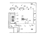
本実施の形態は、半導体製品を製造するためのクリーンルームに本発明を適用した形態である。半導体製品を製造するためのクリーンルームは、図1に示すように、パネル101及びファンフィルタユニット102によって形成される天井と、通気性を有するグレイチング床103によって形成される床と、パネル104によって形成される壁とによって形成されている。クリーンルームの天井裏には上部チャンバ105が形成され、クリーンルームの床下には下部チャンバ106が形成され、クリーンルームの壁の裏側には上部チャンバ105及び下部チャンバ106を接続するリターンチャンバ107が形成されている。
【0034】
ファンフィルタユニット102は、上部チャンバ105の空気をファンによってフィルタに通し、クリーンルームに供給するユニットである。上部チャンバ105の空気は、ファンフィルタユニット102のフィルタを通ってクリーンルームに供給される。クリーンルームに供給された空気は、グレイチング床103を通過して下部チャンバ106に送られる。下部チャンバに送られた空気は、下部チャンバ106からリターンチャンバ107を通って上部チャンバ105に送られる。図1に示すクリーンルームは、このような空気の循環が行われる循環式のクリーンルームである。
【0035】
前記クリーンルームには、シリコンウエハの製造装置108と、これに隣接するハンドリングチャンバ109とが設けられている。ハンドリングチャンバ109は、シリコンウエハの製造装置108からシリコンウエハを受け取るための開閉自在な第一の扉110と、これに対向する位置に設けられる開閉自在な第二の扉111と、第一の扉110及び第二の扉111を介してシリコンウエハを搬送するためのハンドリングアーム112と、ハンドリングチャンバ109内の空気を前記クリーンルームに排気するための差圧排気口113とを有する。
【0036】
ハンドリングチャンバ109の第二の扉111の外側には、ウエハ搬送ボックス114が気密にかつ自在に接続することができる。ハンドリングアーム112は、シリコンウエハの製造装置108からウエハ搬送ボックス114にシリコンウエハを搬送する装置である。ウエハ搬送ボックス114は、このボックスを把持するアームを有する搬送車115によって搬送される。なお差圧排気口113は、例えば前記クリーンルームに対してハンドリングチャンバ109内が正圧である場合に開口する差圧ダンパを有し、ハンドリングチャンバ109内に前記クリーンルームからの空気の流入を防ぐ排気口である。
【0037】
下部チャンバ106には、清浄空気生成装置1が設けられている。清浄空気生成装置1は、サプライダクト116を介してハンドリングチャンバ109に接続されている。清浄空気生成装置1は、下部チャンバ106から空気を取り入れることができ、この空気と別系統から供給される空気とから清浄空気を生成し、サプライダクト116を通じてハンドリングチャンバ109に清浄空気を供給する装置である。
【0038】
清浄空気生成装置1は、図2に示すように、低露点空気供給手段2と、低露点空気から汚染物質の前駆物質を除去する除去手段3とを有する。
【0039】
低露点空気供給手段2は、前述した乾式減湿システムと同様に構成されている。すなわち低露点空気供給手段2は、シリカゲル又は金属ケイ酸塩を有する回転自在な第一及び第二のロータ4、5と、第一及び第二のロータ4、5に処理空気を順次供給するための処理空気の通気路7と、第二のロータから第一のロータ5、4に再生用空気を順次供給するための再生用空気の通気路8と、第一から第二のロータ4、5のそれぞれのロータに冷却用空気を供給するための冷却用空気の通気路9、10と、処理空気の通気路7において第一及び第二のロータ4、5のそれぞれのロータよりも上流側の処理空気の通気路7にクリーンルームの下部チャンバ106から取り入れた空気を供給する還気用の通気路12とを有する。なお、この実施の形態では、差圧ダンパを介して低露点空気がクリーンルーム内に間接的に供給される。
【0040】
冷却用空気の通気路9は、処理空気の通気路7において第一のロータ4よりも下流側の処理空気の通気路7から分岐し、第一のロータ4を通って、第一のロータ4よりも上流側の処理空気の通気路7に接続される通気路である。冷却用空気の通気路10は、処理空気の通気路7において第二のロータ5よりも上流側の処理空気の通気路7から分岐し、第二のロータ5を通って、再生用空気の通気路8において第二のロータ5よりも上流側の再生用空気の通気路8に接続される通気路である。還気用の通気路12は、三つに分岐し、処理空気の通気路7において各ロータよりも上流側の処理空気の通気路7のそれぞれ接続される通気路である。
【0041】
処理空気の通気路7において各ロータよりも上流側の処理空気の通気路7には、処理空気を冷却するための冷却コイル(C)がそれぞれ設けられている。また、再生用空気の通気路8において各ロータよりも上流側の再生用空気の通気路8には、再生用空気を加熱するための加熱コイル(H)がそれぞれ設けられている。また、各通気路には、バルブ(V)及びファン(F)が必要に応じて適宜設けられている。
【0042】
除去手段3は、図2及び図3に示すように、吸着ロータ13と、吸着ロータ13に対して低露点空気を供給する低露点空気供給部14と、吸着ロータ13に対して再生用空気を供給する再生用空気供給部15とを有する。低露点空気供給部14は、低露点空気供給手段2からの処理空気の通気路7に接続され、再生用空気供給部15は、吸着ロータ13よりも下流側の処理空気の通気路7から分岐した通気路である再生用空気の通気路8に接続されている。除去手段3における再生用空気の通気路8には、吸着ロータ13を通過する前の再生用空気の通気路8中の空気を加熱するための加熱コイルH4が設けられている。また、除去手段3における処理空気の通気路7及び再生用空気の通気路8には、それぞれファンF7、F8が設けられている。
【0043】
吸着ロータ13は、通気性を有し円柱形に形成されたロータであり、例えばセラミックの焼成によって形成され、円柱形の軸方向に延びる多数の通気孔を有するハニカム構造体である。吸着ロータ13の前記通気孔の表面には、シリカゲル、ゼオライト、金属ケイ酸塩等から選ばれる吸着剤が担持されている。吸着剤は、例えば前記吸着剤の粒子を水に分散させた分散液に、前記ハニカム構造体を浸漬した後にこれを焼成することによって吸着ロータ13に担持される。
【0044】
低露点空気供給部14と再生用空気供給部15は、図3に示すように、有底の円筒体の内側を仕切り板によって縦に二つに仕切り、仕切られたそれぞれの底部に開口部を設けたケーシング16によって構成され、このケーシング16を、前記円筒体の内部を吸着ロータ13に向けて吸着ロータ13の端面にそれぞれ配置することにより形成されている。
【0045】
低露点空気供給手段2では、第一及び第二のロータ4、5は、それぞれ、処理空気の通気路7、再生用空気の通気路8及びそれぞれの冷却用空気の通気路にまたがって移動するように回転し、かつ処理空気の通気路7から再生用空気の通気路8を経て冷却用空気の通気路に向かう方向に回転する。低露点空気供給手段2では、処理空気は、各ロータを通過するたびに、空気中の水分及び水に溶けやすい有機化合物及び無機物質が除去され、第二のロータ5を通過した後では、露点温度が−80℃程度の低露点空気となる。
【0046】
除去手段3では、低露点空気供給手段2から供給される低露点空気が吸着ロータ13を通過するときに、低露点空気中の一酸化窒素、二酸化窒素、及びオゾン等の比較的極性の低い物質に前記吸着剤が作用する。吸着剤は、これらの物質を吸着又は分解し、これらの物質を低露点空気から除去する。このように、清浄空気生成装置1によれば、前記の物質が除去された清浄な低露点空気を連続して生成することができる。
【0047】
前述した清浄空気生成装置において、除去手段3の吸着剤として金属ケイ酸塩を用いたときの窒素酸化物濃度の変化及び除去率を表1に示す。水に溶けやすい窒素酸化物はインピンジャー法で測定し、その他の窒素酸化物は、化学発光法分析計(日本サーモエレクトロン社製、Model 42C−TL、及びModel 17C)を用いて測定した(乾式法)。
【0048】
【表1】

表1からわかるように、低露点空気中に含まれる、水に溶けやすい窒素酸化物は、その他の窒素酸化物に比べてその量が非常に少なく、全体の1/100程度である。この結果より、汚染物質を生成し得る物質の量としては、水に溶けやすい窒素酸化物に比べてその他の窒素酸化物の方がはるかに多いことがわかる。したがって、乾式法で測定されるような水に溶けにくい窒素酸化物を除去することは、窒素酸化物から生成され得る汚染物質のクリーンルームでの発生を防止する上で、非常に有効であることがわかる。
【0050】
また前述した清浄空気生成装置において、除去手段3の吸着剤として金属ケイ酸塩を用いたときのオゾン濃度の変化及び除去率を表2に示す。表2に示すように、前記清浄空気生成装置によれば、外気の98%以上のオゾンが除去された低露点空気を生成することができる。
【0051】
【表2】
一酸化窒素や二酸化窒素等の窒素酸化物やオゾンが空気中から除去される理由としては、露点温度が−80℃以下の低露点空気には、水や前記極性分子のように、前記吸着剤に優先的に吸着される物質がほとんど含まれていないので、前記窒素酸化物やオゾンのように、通常では吸着剤が作用しにくい物質に吸着剤が作用するためと考えられる。
【0053】
本実施の形態では、このように窒素酸化物及びオゾンが除去された低露点空気が図1に示すハンドリングチャンバ109に供給される。前記化学反応式(1)に示したように、窒素酸化物、オゾン、及び水が存在する場合では、汚染物質である硝酸が生成することがあり得るが、本実施の形態では、窒素酸化物、オゾン、及び水が除去された低露点空気が生成されることから、ハンドリングチャンバ109内での汚染物質の発生を防止することができる。
【0054】
また窒素酸化物及びオゾンは、強い酸化力を有することが知られているが、本実施の形態によれば、これらの物質が除去された低露点空気が生成されることから、ハンドリングチャンバ109内におけるこれらの物質の影響(例えばシリコンウエハでの酸化膜の生成等)をより小さくすることができる。
【0055】
本発明の実施の形態の他の適用例を示す。
図4は、本発明の実施の形態の清浄空気生成装置を、クリーンルーム中に設けられたシリコンウエハの保管庫に適用した例を示す。図4に示すクリーンルームは、シリコンウエハの製造装置108及びハンドリングチャンバ109に代えてシリコンウエハの保管庫117が設けられていること、清浄空気生成装置1はサプライダクト116を介してシリコンウエハの保管庫117に清浄な低露点空気を供給すること、シリコンウエハの保管庫117と清浄空気生成装置1とはリターンダクト118で接続されていること、及び清浄空気生成装置1の還気用の通気路12にはリターンダクト118からの還気が供給されること以外は、図1に示すクリーンルームと同じ構成である。
【0056】
シリコンウエハの保管庫117は、前述した第二の扉111と同じ構造の第三の扉119を有する。また、シリコンウエハの保管庫117には、供給される空気から粒子状の汚染物質を除去するためのフィルタ(f)等が必要に応じて設けられる。
【0057】
シリコンウエハの保管庫117には、窒素酸化物及びオゾンが除去された清浄な低露点空気が清浄空気生成装置1から供給される。また、シリコンウエハの保管庫117の空気は、差圧排気口113及びリターンダクト118を介して清浄空気生成装置1に戻される。
【0058】
前述したように、窒素酸化物及びオゾンは強い酸化力を有している。前記適用例のように、シリコンウエハがより長時間空気と接触する環境に本発明の実施の形態を適用すると、シリコンウエハでの酸化膜の生成のような、半導体製品への上記物質の悪影響を抑制する上でより一層効果的である。
【0059】
<参考例>
本参考例の清浄空気生成装置は、図5に示すように、低露点空気供給手段20と、除去手段30と、後処理装置40とを有する。
【0060】
低露点空気供給手段20は、処理すべき空気を圧縮する圧縮機21と、圧縮された空気を収容する空気タンク22と、圧縮された空気から水分を除去する減湿装置23と、圧縮機21、空気タンク22、及び減湿装置23を順次接続する処理空気の通気路7と、減湿装置23を通過する再生用空気の通気路8とを有する。処理空気の通気路7には、例えば圧縮前の空気から粒子状の汚染物質を除去するためのフィルタ(f2)や、空気タンク22に収容する前の空気を冷却するための冷却コイル(C4)等が適宜設けられている。
【0061】
減湿装置23は、空気中の水分を吸着するゼオライト等の吸着剤が充填されている第一の吸着塔24及び第二の吸着塔25と、二つのバルブV7、V8を有し処理空気の通気路7においてこれらの吸着塔の入り口同士を接続する通気路aと、二つのバルブV9、V10を有し処理空気の通気路7においてこれらの吸着塔の出口同士を接続する通気路bと、バルブV7及びバルブV8よりもそれぞれの吸着塔寄りの通気路a同士を接続する通気路cと、バルブV9及びバルブV10よりもそれぞれの吸着塔寄りの通気路b同士を接続する通気路dとを有する。通気路cは二つのバルブV11、V12を有し、通気路dは二つのバルブV13、V14を有する。
【0062】
減湿装置23において、空気タンク23側では、バルブV7とV8との間の通気路aと処理空気の通気路7とが接続されており、バルブ11とV12との間の通気路cと再生用空気の通気路8とが接続されている。また、減湿装置23において、除去手段30側では、バルブV9とV10との間の通気路bと処理空気の通気路7とが接続されており、バルブV13とV14との間の通気路dと再生用空気の通気路8とが接続されている。
【0063】
除去手段30は、再生用空気の通気路8において吸着ロータ13よりも上流側で一部が分岐し吸着ロータ13を介して吸着ロータ13よりも下流側の再生用空気の通気路8に接続される冷却用空気の通気路31を有すること、冷却用空気供給部(図示せず)が吸着ロータ13のケーシングに設けられていること、及び吸着ロータ13は低露点空気供給部から再生用空気供給部を経て冷却用空気供給部に向かう回転方向で回転すること以外は、前述した除去手段3と同様に構成されている。なお、冷却用空気供給部は、図3に示す低露点空気供給部や再生用空気供給部と同様に、仕切り板によって構成される。
【0064】
後処理装置40には、空気中の粒子状の物質を除去するフィルタ(f3)を有する装置や、空気中に含まれる有機物質を空気中から除去するためのオイルセパレータが用いられる。
【0065】
低露点空気供給手段20では、圧縮機21によって圧縮された空気は、必要に応じて冷却コイルC4で冷却されて空気タンク22に収容される。空気タンク22に収容された圧縮空気は、減湿装置23において第一の吸着塔24又は第二の吸着塔25に送られる。吸着塔では、吸着塔に収容されている吸着剤によって、吸着塔に送られた圧縮空気から水分が吸着され除去される。
【0066】
減湿装置23において、第一の吸着塔24によって前記圧縮空気から水分を除去する場合では、バルブV7及びV9を開き、バルブV8、V11、V13、及びV10を閉じる。また第一の吸着塔24を運転しながら第二の吸着塔25の吸着能力を再生する場合では、バルブV14及びV12を開き、第二の吸着塔25に再生用空気の通気路8の空気を通し、第二の吸着塔25に収容された吸着剤の吸着能力を再生する。なお、再生用空気の再生力を高めるために、除去手段30と通気路dとの間の再生用空気の通気路8に加熱コイル等の空気の加熱手段を設けても良い。
【0067】
同様に、第二の吸着塔25によって前記圧縮空気から水分を除去する場合では、バルブV8及びV10を開き、バルブV7、V12、V14、及びV9を閉じる。また第二の吸着塔25を運転しながら第一の吸着塔24の吸着能力を再生する場合では、バルブV13及びV11を開き、第一の吸着塔24に収容された吸着剤の吸着能力を再生する。このように、空気タンク22に収容された圧縮空気を第一の吸着塔24又は第二の吸着塔25に通すことによって、露点温度が−80℃程度の低露点空気が生成する。
【0068】
低露点空気供給手段20で生成した低露点空気は、必要に応じて冷却コイルC5によって冷却され、低露点空気供給部に供給され、吸着ロータ13を通る。前記低露点空気は、吸着ロータ13を通過することによって、低露点空気中に含まれる一酸化窒素及び二酸化窒素等の窒素酸化物、及びオゾンが低露点空気から除去され、これらの物質が除かれた清浄な低露点空気となる。
【0069】
吸着ロータ13を通過した低露点空気は、一部は後処理装置40に送られ、一部は再生用空気の通気路8に送られる。後処理装置40に送られた低露点空気は、さらに前記ハンドリングチャンバや前記シリコンウエハの保管庫等の供給先に供給される。
【0070】
再生用空気の通気路8に送られた低露点空気は、一部は加熱コイルH4に送られ、一部は冷却用空気の通気路31に送られる。加熱コイルH4に送られた低露点空気は、加熱され、再生用空気供給部に供給され、吸着ロータ13を通過する。これにより、吸着ロータ13の吸着剤に吸着された物質が吸着剤から放出され、又は吸着剤表面で分解され、前記吸着剤の吸着能力が再生する。
【0071】
再生用空気供給部で加熱された吸着ロータ13の一部分が吸着ロータ13の回転によって冷却用空気供給部に移動しており、冷却用空気の通気路31に送られた低露点空気は、この部分を通過する。これにより、加熱された吸着ロータ13が冷却され、低露点空気供給部における吸着剤の吸着効率がより一層向上する。吸着ロータ13を通過した冷却用の低露点空気は、冷却後に、ヒータH4で加熱され吸着ロータ13を再生した後の再生用の低露点空気と合流する。合流した低露点空気は、前述したように、第一の吸着塔24又は第二の吸着塔25に送られ、吸着塔に収容されている吸着剤の吸着能力を再生する。
【0072】
本実施の形態によれば、圧縮空気から水分を除去するための二つの吸着塔を有し、これらの吸着塔のそれぞれに対して、処理すべき空気の供給と再生用空気の供給とを自在に切り替えられる低露点空気供給手段20を用いることから、低露点の圧縮空気を連続して生成することができ、かつこの低露点の圧縮空気から、一酸化窒素や二酸化窒素等の窒素酸化物やオゾン等の汚染物質の前駆物質を連続して除去することができるので、前記前駆物質が除去された清浄な低露点空気を連続して生成することができる。
【0073】
また、本参考例では、吸着剤の吸着能力の再生時に加熱された吸着ロータ13を冷却した後に、前記前駆物質の除去に再び用いることから、前記前駆物質の除去効率を向上させる上でより一層効果的である。
【0074】
<第二の実施の形態>
本実施の形態の清浄空気生成装置は、図6に示すように、減湿装置23に代えて膜式減湿装置51を用いる以外は、参考例と同様に構成されている。
【0075】
膜式減湿装置51は、例えば、円筒形の容器と、この容器に収容される中空糸膜の束と、前記容器に収容された中空糸膜の中空部分に圧縮空気を供給するための圧縮空気の通気口と、前記容器と前記中空糸膜との隙間に再生用空気を供給するための再生用空気の通気口とを有する。前記圧縮空気の通気口には、処理空気の通気路7が接続されており、前記再生用空気の通気口には、再生用空気の通気路8が、処理空気の通気路7の外周を取り巻くように接続されている。なお、処理空気の通気路7と再生用空気の通気路8は、前記中空部分における圧縮空気の流れ方向と前記容器内における再生用空気の流れ方向が逆方向になるように接続されている。
【0076】
前記圧縮空気の通気口から、空気タンク22からの圧縮空気を前記中空糸膜に通すと、高分子材料で形成されている中空糸膜は水蒸気を透過させやすく空気を透過させにくい性質を有することから、圧縮空気の水分は中空糸膜の外側に透過する。中空糸膜を透過した水分は、吸着ロータ13における吸着剤の再生に用いられた低露点空気に吸収され、前記容器から排出される。このように、前記中空糸膜に圧縮空気を通すことによって、露点温度が−80℃程度の低露点空気が連続して生成される。
【0077】
なお、前記中空糸膜による水分の透過の効率をより向上させるために、吸着ロータ13と膜式減湿装置51との間の再生用空気の通気路8に冷却コイル等の空気の冷却手段を設けても良い。
【0078】
本実施の形態によれば、膜式減湿装置51を用いて圧縮空気から水分を除去することから、簡単な構成で低露点の圧縮空気を連続して生成することができ、かつこの低露点の圧縮空気から、一酸化窒素や二酸化窒素等の窒素酸化物やオゾン等の汚染物質の前駆物質を連続して除去することができるので、前記前駆物質が除去された清浄な低露点空気を簡単な構成で連続して生成することができる。
【0079】
また、本実施の形態では、吸着剤の吸着能力の再生時に加熱された吸着ロータ13を冷却した後に、前記前駆物質の除去に再び用いることから、前記前駆物質の除去効率を向上させる上でより一層効果的である。
【0080】
【発明の効果】
本発明の清浄空気生成装置は、汚染物質の前駆物質が除かれた低露点空気を生成する装置であって、低露点空気供給手段と、低露点空気から汚染物質の前駆物質を除去する除去手段とを有し、低露点空気供給手段は、除去手段に低露点空気を供給する手段であり、除去手段は、空気中の極性分子を吸着する吸着剤を、低露点空気供給手段から供給される低露点空気に接触する位置に有する手段であることから、空気中の汚染物質及びその前駆物質が除かれた清浄な低露点空気を生成することができる。
【0081】
また、本発明では、低露点空気供給手段は、露点温度が−80℃以下の低露点空気を供給する手段であると、前記前駆物質を低露点空気から効率よく除去する上でより一層効果的である。
【0082】
また、本発明では、除去手段は、通気性を有し移動自在に設けられる吸着部材と、この吸着部材を通過する空気に接触する位置にある吸着剤と、吸着部材に対して低露点空気を供給する低露点空気供給部と、吸着部材に対して吸着剤の吸着能力を再生するために吸着部材を加熱する加熱部とを有し、吸着部材は、低露点空気供給部と加熱部とにまたがって移動すると、前記前駆物質を低露点空気から効率よく、かつ連続して除去する上でより一層効果的であり、吸着部材は円柱形に形成された吸着ロータであるとさらに一層効果的である。
【0083】
また、本発明では、吸着剤は、シリカゲル、ゼオライト、及び金属ケイ酸塩の中から選択される一種又は二種以上であると、汚染物質及びその前駆物質が除去された清浄な低露点空気を生成する上でより一層効果的である。
【図面の簡単な説明】
【図1】本発明の一実施の形態の清浄空気生成装置を、シリコンウエハを製造するためのクリーンルームに適用したときの構成を示す図である。
【図2】本発明の一実施の形態の清浄空気生成装置の構成を示す図である。
【図3】図2に示す清浄空気生成装置の吸着手段3の構成の要部を示す図である。
【図4】本発明の一実施の形態の清浄空気生成装置を、シリコンウエハを製造するためのクリーンルームに適用したときの他の構成を示す図である。
【図5】参考例の清浄空気生成装置の構成を示す図である。
【図6】本発明の他の実施の形態の清浄空気生成装置の構成を示す図である。[0001]
BACKGROUND OF THE INVENTION
The present invention provides a device for producing clean air that can be supplied to a clean room. In place In particular, a device that generates clean air from which contaminants and their precursors are removed in a clean room for manufacturing electronic parts such as semiconductors and liquid crystal elements, and products such as electronic materials. In place Related.
[0002]
[Prior art]
As a method and an apparatus for generating clean air, dry dehumidifiers having a rotatable rotor having silica gel or metal silicate were connected in series in three stages, and dehumidified by the first dry dehumidifier. A method of dehumidifying the air with the second-stage dry dehumidifier, and further dehumidifying the air treated with the second-stage dry dehumidifier with the third-stage dry dehumidifier, and such means Devices having the following are known: Further, according to such a method and apparatus, it is known that pollutants of inorganic gas components such as ammonia, hydrogen chloride, nitrogen oxides, sulfur oxides are adsorbed from the air and removed at an outlet concentration of 1 ppb or less. (For example, refer to Patent Document 1).
[0003]
[Patent Document 1]
JP 2001-38137 A
[0004]
[Problems to be solved by the invention]
In the measurement of contaminants of inorganic gas components, a method is generally used in which the contaminants are collected by an impinger and measured. In this method, substances that are not soluble in water and substances that are difficult to dissolve in water are not collected and measured. Among such water-insoluble substances and poorly water-soluble substances, these substances react with each other in the gas phase, or these substances and water react with each other in the gas phase, thereby removing the contaminants. There are substances to form (precursors).
[0005]
On the other hand, in a clean room used as a manufacturing site for semiconductor products, pharmaceuticals, etc., depending on the type and state of the product and the work process in the clean room, the precursor reacts in the aforementioned gas phase to form the pollutant. There are things to do.
[0006]
The present invention has been made in view of the above matters, and is a device that generates clean low dew point air from which contaminants in air and precursors thereof are removed. Place The issue is to provide.
[0007]
[Means for Solving the Problems]
Many gaseous inorganic compounds are easily dissolved in water or react easily with water. Such a substance can be effectively removed using a known means such as a chemical filter having an adsorbent such as activated carbon or a chemical washer that sprays water on the air. However, some gaseous inorganic compounds are difficult to dissolve in water. A substance that is hardly soluble in water reacts with each other to become a substance that is easily soluble in water, and the reaction between this substance and water may generate a contaminant.
[0008]
For example, nitrogen oxides include substances that are difficult to dissolve in water, such as nitric oxide. However, nitric oxide reacts with ozone to generate nitrogen dioxide as shown in chemical reaction formula (1) below. The generated nitrogen dioxide reacts with water to generate nitric acid and nitric oxide as shown in chemical reaction formula (2) below. Nitric acid is regarded as a contaminant in the manufacture of semiconductor products in a clean room.
[0009]
[Chemical 1]
NO + O Three → NO 2 + O 2 (1)
[0010]
[Chemical formula 2]
3NO 2 + H 2 O → 2HNO Three + NO (2)
[0011]
In a clean room used for the manufacture of semiconductor products, depending on the processes performed in the clean room, an environment where there is sufficient energy to advance the reaction, such as electron beam irradiation, may be formed, The chemical reaction may proceed in a clean room. Therefore, in order to increase the yield of products in the clean room, in addition to water and pollutants, air that is free of substances that can generate pollutants such as nitrogen monoxide, nitrogen dioxide, and ozone is supplied. is important.
[0012]
The present invention supplies low dew point air containing almost no moisture to an adsorbent that adsorbs polar molecules in the air that can become pollutants in a clean room, and the polar molecules that are not normally adsorbed by the adsorbent from air containing polar molecules. A device that adsorbs or removes (pollutant) precursors with an adsorbent and generates low dew point air that is unlikely to generate pollutants in a clean space such as a clean room. In place is there.
[0013]
That is, the present invention is an apparatus for generating low dew point air from which contaminant precursors have been removed, and includes low dew point air supply means and removal means for removing contaminant precursors from low dew point air. The low dew point air supply means is a means for supplying low dew point air to the removal means, and the removal means supplies the adsorbent that adsorbs polar molecules in the air to the low dew point air supply means from the low dew point air supply means. It is the clean air production | generation apparatus which is a means to have in the position which contacts.
[0014]
Generally, organic and inorganic polar molecules are removed along with the removal of moisture from the air during the generation of low dew point air. Therefore, according to the above configuration, the adsorbent acts on the precursor contained in the low dew point air, and the precursor is removed or detoxified from the low dew point air by a phenomenon such as adsorption or decomposition. It is possible to generate clean low dew point air from which air is removed.
[0015]
The low dew point air supply means is means for supplying low dew point air to the removal means. As such low dew point air supply means, various conventionally known means can be used. As such low dew point air supply means, for example, means for generating and supplying low dew point air from air such as outside air, means for supplying low dew point air accommodated in a container, and the like are used.
[0016]
The removal rate of the precursor from the low dew point air tends to increase in proportion to the low dew point temperature of the low dew point air. Therefore, in the present invention, the dew point temperature of the low dew point air supplied to the removing means can be appropriately set according to the type of the precursor and the removal rate to be achieved, but the low dew point air supplying means A means for supplying low dew point air having a dew point temperature of −80 ° C. or lower is preferable for efficiently removing the precursor from the low dew point air.
[0017]
As a means for generating and supplying low dew point air, a known device that generates low dew point air by removing moisture from the air can be used. As such a device, for example, a dehumidifying device having a compressor that compresses air and an adsorption-type dehumidifier that dehumidifies compressed air with a dehumidifying adsorbent, a compressor that compresses air, Examples thereof include a dehumidifying device having a membrane type dehumidifier that dehumidifies compressed air by a separation membrane such as a hollow fiber membrane, and a dry dehumidifying system in which the above-described dry dehumidifying devices are connected in series in three stages. In the present invention, it is possible to efficiently remove the contaminant precursor from the low dew point air by using a means for adsorbing and removing moisture in the air by a known dehumidifying adsorbent and generating low dew point air. Is preferable.
[0018]
Examples of means for supplying the low dew point air accommodated in the container include a cylinder for accommodating the low dew point air.
[0019]
The removing means is a means for removing the contaminant precursor from the low dew point air, and the adsorbent that adsorbs polar molecules in the air is brought into contact with the low dew point air supplied from the low dew point air supply means. Have. The removing means may be a removing means that is fixedly disposed in the air passage to be treated, as in a known chemical filter, but repeatedly performs adsorption and regeneration of the adsorption capacity of the adsorbent. It is preferable to remove the precursor from the low dew point air efficiently and continuously.
[0020]
Such a removing means is not particularly limited, but for example, an adsorbing member that is air permeable and movably provided, the adsorbent that is in contact with the air passing through the adsorbing member, and the adsorbing member A low dew point air supply unit that supplies low dew point air and a heating unit that heats the adsorption member to regenerate the adsorption capacity of the adsorbent with respect to the adsorption member. Removal means that moves across the heating section and the heating section.
[0021]
As the adsorbing member, various members conventionally known can be used as long as the adsorbing member has air permeability and can be provided movably. The material of the adsorption member is not particularly limited. Examples of such an adsorbing member include a honeycomb structure formed of ceramic paper or a fired body of silica, an endless belt formed of ceramic paper or glass cloth, and the like. In the present invention, it is more preferable that the adsorbing member is an adsorbing rotor formed in a cylindrical shape in order to efficiently and continuously remove the precursor from low dew point air.
[0022]
The means for movably providing the adsorption member is not particularly limited as long as it is an appropriate means according to the form of the adsorption member. As such means, for example, when the suction member is a rotor, a motor having power transmission means such as a gear and a belt that transmits rotational motion to the rotor can be cited. For example, when the suction member is an endless belt And a driving pulley that pivotally supports the endless belt. By using such means and appropriately arranging the low dew point air supply unit and the heating unit, which will be described later, or arranging the fixing member with respect to the low dew point air supply unit and the heating unit, the low dew point air supply unit and the heating unit are arranged. The adsorption member can be moved across the two.
[0023]
The said low dew point air supply part is a member which supplies low dew point air with respect to an adsorption member, If it is such a member, it will not specifically limit. Such a low dew point air supply part can be appropriately provided according to the form of the adsorbing member. Such a low dew point air supply part is comprised by members, such as a partition plate which partitions off these inside, for example as needed, such as a casing and a chamber.
[0024]
The heating unit is a member that heats the adsorption member in order to regenerate the adsorption capability of the adsorbent with respect to the adsorption member, and is not particularly limited as long as it is such a member. Such a heating unit can be appropriately provided according to the form of the adsorption member. Examples of such a heating unit include a regeneration air supply unit that supplies regeneration air that is air heated to the adsorption member, and a heater that heats the adsorption member. The regeneration air supply unit can be configured in the same manner as the low dew point air supply unit described above.
[0025]
Moreover, it is preferable that the removal means which has the said heating part has a cooling air supply part which supplies the air for cooling with respect to an adsorption member, before the heated adsorption member moves to a low dew point air supply part. . Such a configuration is preferable for efficiently adsorbing the contaminant precursor. As the cooling air, low dew point air that has passed through the removing means or air such as return air from a clean room can be used. The cooling air supply unit can be configured in the same manner as the low dew point air supply unit described above.
[0026]
The adsorbent is not particularly limited as long as it is an adsorbent that adsorbs polar molecules in the air. As such an adsorbent, conventionally known various adsorbents can be used. Examples of such an adsorbent include activated carbon, silica gel, alumina, zeolite, and metal silicate. In the present invention, the adsorbent is preferably one or more selected from silica gel, zeolite, and metal silicate in order to remove the pollutant precursor from the low dew point air. The adsorbent can be selected according to the type of contaminant precursor. For example, it will be described later that the adsorbent is one or more selected from silica gel or metal silicate. Nitrogen dioxide, nitric oxide and ozone are preferably removed from the low dew point air at once, and the adsorbent is preferably zeolite from the viewpoint of removing ozone from the low dew point air.
[0027]
The components of the clean air generator of the present invention are not limited to the components described above. The clean air generating apparatus of the present invention may have additional components as required for the purpose of use of the clean air to be generated and desired properties. Such other components include, for example, a dehumidifying device for lowering the dew point temperature of the low dew point air from which the precursor has been removed by the removing means, and particulates such as dust from air such as the low dew point air. Air purification means such as HEPA filters that remove pollutants, temperature adjustment means such as heating and cooling coils that adjust the dry bulb temperature of air such as low dew point air, air blowing means such as fans, butterfly valves and automatic valves And a flow rate adjusting means such as
[0033]
DETAILED DESCRIPTION OF THE INVENTION
<First embodiment>
In the present embodiment, the present invention is applied to a clean room for manufacturing semiconductor products. As shown in FIG. 1, a clean room for manufacturing a semiconductor product is formed by a ceiling formed by a
[0034]
The
[0035]
The clean room is provided with a silicon
[0036]
A
[0037]
The
[0038]
As shown in FIG. 2, the clean air generating apparatus 1 includes a low dew point
[0039]
The low dew point air supply means 2 is configured similarly to the dry dehumidification system described above. That is, the low dew point air supply means 2 sequentially supplies process air to the rotatable first and
[0040]
The cooling air ventilation path 9 branches from the processing
[0041]
A cooling coil (C) for cooling the processing air is provided in the processing
[0042]
As shown in FIGS. 2 and 3, the removing unit 3 includes an
[0043]
The
[0044]
As shown in FIG. 3, the low dew point
[0045]
In the low dew point air supply means 2, the first and
[0046]
In the removing means 3, when the low dew point air supplied from the low dew point air supply means 2 passes through the
[0047]
Table 1 shows changes in nitrogen oxide concentration and removal rate when metal silicate is used as the adsorbent of the removing means 3 in the above-described clean air generating apparatus. Nitrogen oxides easily soluble in water were measured by the impinger method, and other nitrogen oxides were measured using a chemiluminescence analyzer (manufactured by Nippon Thermo Electron, Model 42C-TL and Model 17C) Law).
[0048]
[Table 1]
As can be seen from Table 1, the amount of nitrogen oxides contained in the low dew point air that is soluble in water is very small compared to other nitrogen oxides, which is about 1/100 of the total. From this result, it can be seen that the amount of substances that can generate pollutants is much larger in other nitrogen oxides than in nitrogen oxides that are easily soluble in water. Therefore, removing nitrogen oxides that are hardly soluble in water as measured by the dry method is very effective in preventing the generation of contaminants that can be generated from nitrogen oxides in a clean room. Recognize.
[0050]
Table 2 shows the change in ozone concentration and the removal rate when metal silicate is used as the adsorbent of the removing means 3 in the above-described clean air generating apparatus. As shown in Table 2, according to the clean air generator, low dew point air from which 98% or more of ozone from the outside air has been removed can be generated.
[0051]
[Table 2]
The reason why nitrogen oxides such as nitrogen monoxide and nitrogen dioxide and ozone are removed from the air is that, in low dew point air with a dew point temperature of −80 ° C. or lower, the adsorbent, like water or the polar molecule, This is presumably because the adsorbent acts on substances that are difficult to act on normally, such as nitrogen oxides and ozone.
[0053]
In this embodiment, the low dew point air from which nitrogen oxides and ozone have been removed is supplied to the
[0054]
Nitrogen oxides and ozone are known to have a strong oxidizing power. However, according to the present embodiment, low dew point air from which these substances are removed is generated. The influence (for example, the production | generation of the oxide film in a silicon wafer) of these substances in can be made smaller.
[0055]
Another application example of the embodiment of the present invention will be described.
FIG. 4 shows an example in which the clean air generation apparatus according to the embodiment of the present invention is applied to a silicon wafer storage provided in a clean room. In the clean room shown in FIG. 4, a
[0056]
The
[0057]
A clean low dew point air from which nitrogen oxides and ozone are removed is supplied from the clean air generator 1 to the
[0058]
As described above, nitrogen oxides and ozone have a strong oxidizing power. When the embodiment of the present invention is applied to an environment in which a silicon wafer is in contact with air for a longer time as in the above application example, the adverse effect of the substance on the semiconductor product, such as formation of an oxide film on the silicon wafer, is reduced. It is more effective in suppressing.
[0059]
< Reference example >
Book Reference example As shown in FIG. 5, the clean air generation apparatus includes a low dew point air supply means 20, a removal means 30, and a
[0060]
The low dew point air supply means 20 includes a
[0061]
The
[0062]
In the
[0063]
The removing means 30 is partially branched upstream of the
[0064]
As the
[0065]
In the low dew point air supply means 20, the air compressed by the
[0066]
In the
[0067]
Similarly, when moisture is removed from the compressed air by the
[0068]
The low dew point air generated by the low dew point air supply means 20 is cooled by the cooling coil C5 as necessary, supplied to the low dew point air supply unit, and passes through the
[0069]
Part of the low dew point air that has passed through the
[0070]
A part of the low dew point air sent to the regeneration
[0071]
A part of the
[0072]
According to the present embodiment, there are two adsorption towers for removing moisture from the compressed air, and the supply of air to be treated and the supply of regeneration air can be freely performed for each of these adsorption towers. The low dew point air supply means 20 can be used to continuously generate low dew point compressed air, and from this low dew point compressed air, nitrogen oxides such as nitrogen monoxide and nitrogen dioxide, Since contaminant precursors such as ozone can be continuously removed, clean low dew point air from which the precursors have been removed can be continuously generated.
[0073]
Also book Reference example Then, after the
[0074]
<No. two Embodiment>
As shown in FIG. 6, the clean air generation device of the present embodiment is configured by using a
[0075]
The membrane
[0076]
When compressed air from the
[0077]
In order to further improve the efficiency of moisture permeation through the hollow fiber membrane, an air cooling means such as a cooling coil is provided in the
[0078]
According to the present embodiment, the moisture is removed from the compressed air using the membrane
[0079]
Further, in the present embodiment, after the
[0080]
【The invention's effect】
The clean air generating apparatus of the present invention is an apparatus for generating low dew point air from which contaminant precursors have been removed, including low dew point air supply means and removal means for removing contaminant precursors from the low dew point air. The low dew point air supply means is means for supplying low dew point air to the removal means, and the removal means is supplied with an adsorbent that adsorbs polar molecules in the air from the low dew point air supply means. Since it is a means having a position in contact with the low dew point air, it is possible to generate clean low dew point air from which contaminants and precursors in the air are removed.
[0081]
In the present invention, when the low dew point air supply means is a means for supplying low dew point air having a dew point temperature of −80 ° C. or lower, it is more effective in efficiently removing the precursor from the low dew point air. It is.
[0082]
Further, in the present invention, the removing means has a breathable adsorption member provided so as to be movable, an adsorbent located in contact with the air passing through the adsorption member, and low dew point air to the adsorption member. A low dew point air supply unit to supply, and a heating unit for heating the adsorption member to regenerate the adsorption capacity of the adsorbent to the adsorption member. The adsorption member is divided into a low dew point air supply unit and a heating unit. When moved across, it is more effective in removing the precursor from the low dew point air efficiently and continuously, and it is even more effective if the adsorption member is an adsorption rotor formed in a cylindrical shape. is there.
[0083]
In the present invention, when the adsorbent is one or more selected from silica gel, zeolite, and metal silicate, clean low dew point air from which contaminants and precursors thereof are removed is used. It is much more effective in producing.
[Brief description of the drawings]
FIG. 1 is a diagram showing a configuration when a clean air generation apparatus according to an embodiment of the present invention is applied to a clean room for manufacturing a silicon wafer.
FIG. 2 is a diagram showing a configuration of a clean air generation apparatus according to an embodiment of the present invention.
FIG. 3 is a diagram showing a main part of the configuration of the adsorbing means 3 of the clean air generating device shown in FIG. 2;
FIG. 4 is a diagram showing another configuration when the clean air generating apparatus of one embodiment of the present invention is applied to a clean room for manufacturing a silicon wafer.
[Figure 5] Reference example It is a figure which shows the structure of a clean air production | generation apparatus.
FIG. 6 is a diagram showing a configuration of a clean air generation device according to another embodiment of the present invention.
Claims (2)
前記低露点空気供給手段は、前記除去手段に露点温度が−80℃以下の低露点空気を原料として供給する手段であり、
前記除去手段は、空気中の極性分子を吸着する吸着剤を、前記低露点空気供給手段から供給される低露点空気に接触する位置に有する手段であり、
前記低露点空気供給手段は、処理すべき空気を圧縮する圧縮機と、圧縮された空気を収容する空気タンクと、圧縮された空気から水分を除去する膜式減湿装置と、前記圧縮機、前記空気タンク、及び前記膜式減湿装置を順次接続する処理空気の通気路と、前記膜式減湿装置を通過する再生用空気の通気路とを有し、
前記膜式減湿装置は、円筒形の容器と、前記容器に収容される中空糸膜の束と、前記容器に収容された中空糸膜の中空部分に圧縮空気を供給するための圧縮空気の通気口と、前記容器と前記中空糸膜との隙間に再生用空気を供給するための再生用空気の通気口とを有し、
前記除去手段から排出された前記低露点空気は、ハンドリングチャンバやシリコンウェハの保管庫等の供給先に供給され、差圧ダンパを介して前記クリーンルーム内に間接的に供給される、清浄空気生成装置。An apparatus for generating low dew point air from which contaminant precursors have been removed and supplying the air to a clean space, comprising low dew point air supply means and removal means for removing contaminant precursors from low dew point air. And
The low dew point air supply means is means for supplying low dew point air having a dew point temperature of −80 ° C. or less as a raw material to the removing means,
The removing means is a means having an adsorbent that adsorbs polar molecules in the air at a position in contact with the low dew point air supplied from the low dew point air supply means,
The low dew point air supply means includes: a compressor that compresses air to be processed; an air tank that stores the compressed air; a membrane dehumidifier that removes moisture from the compressed air; and the compressor, An air passage for processing air that sequentially connects the air tank and the membrane type dehumidifying device, and an air passage for regeneration air that passes through the membrane type dehumidifying device,
The membrane type dehumidifier includes a cylindrical container, a bundle of hollow fiber membranes accommodated in the container, and compressed air for supplying compressed air to a hollow portion of the hollow fiber membrane accommodated in the container. A ventilation hole, and a regeneration air ventilation hole for supplying regeneration air to the gap between the container and the hollow fiber membrane,
The low dew point air discharged from the removing means is supplied to a supply destination such as a handling chamber or a silicon wafer storage, and is indirectly supplied into the clean room via a differential pressure damper. .
前記低露点空気供給手段は、前記除去手段に露点温度が−80℃以下の低露点空気を原料として供給する手段であり、
前記除去手段は、空気中の極性分子を吸着する吸着剤を、前記低露点空気供給手段から供給される低露点空気に接触する位置に有する手段であり、
前記低露点空気供給手段は、処理すべき空気を圧縮する圧縮機と、圧縮された空気を収容する空気タンクと、圧縮された空気から水分を除去する膜式減湿装置と、前記圧縮機、前記空気タンク、及び前記膜式減湿装置を順次接続する処理空気の通気路と、前記膜式減湿装置を通過する再生用空気の通気路とを有し、
前記膜式減湿装置は、円筒形の容器と、前記容器に収容される中空糸膜の束と、前記容器に収容された中空糸膜の中空部分に圧縮空気を供給するための圧縮空気の通気口と、前記容器と前記中空糸膜との隙間に再生用空気を供給するための再生用空気の通気口とを有する、
清浄空気生成装置。An apparatus for generating low dew point air from which contaminant precursors have been removed and supplying the air to a clean space, comprising low dew point air supply means and removal means for removing contaminant precursors from low dew point air. And
The low dew point air supply means is means for supplying low dew point air having a dew point temperature of −80 ° C. or less as a raw material to the removing means,
The removing means is a means having an adsorbent that adsorbs polar molecules in the air at a position in contact with the low dew point air supplied from the low dew point air supply means,
The low dew point air supply means includes: a compressor that compresses air to be processed; an air tank that stores the compressed air; a membrane dehumidifier that removes moisture from the compressed air; and the compressor, An air passage for processing air that sequentially connects the air tank and the membrane type dehumidifying device, and an air passage for regeneration air that passes through the membrane type dehumidifying device,
The membrane type dehumidifier includes a cylindrical container, a bundle of hollow fiber membranes accommodated in the container, and compressed air for supplying compressed air to a hollow portion of the hollow fiber membrane accommodated in the container. A ventilation hole, and a regeneration air ventilation hole for supplying regeneration air to a gap between the container and the hollow fiber membrane,
Clean air generator.
Priority Applications (1)
| Application Number | Priority Date | Filing Date | Title |
|---|---|---|---|
| JP2002307181A JP4236443B2 (en) | 2002-10-22 | 2002-10-22 | Clean air generator |
Applications Claiming Priority (1)
| Application Number | Priority Date | Filing Date | Title |
|---|---|---|---|
| JP2002307181A JP4236443B2 (en) | 2002-10-22 | 2002-10-22 | Clean air generator |
Publications (2)
| Publication Number | Publication Date |
|---|---|
| JP2004141721A JP2004141721A (en) | 2004-05-20 |
| JP4236443B2 true JP4236443B2 (en) | 2009-03-11 |
Family
ID=32453718
Family Applications (1)
| Application Number | Title | Priority Date | Filing Date |
|---|---|---|---|
| JP2002307181A Expired - Fee Related JP4236443B2 (en) | 2002-10-22 | 2002-10-22 | Clean air generator |
Country Status (1)
| Country | Link |
|---|---|
| JP (1) | JP4236443B2 (en) |
Families Citing this family (3)
| Publication number | Priority date | Publication date | Assignee | Title |
|---|---|---|---|---|
| JP2006261055A (en) * | 2005-03-18 | 2006-09-28 | Sharp Corp | Manufacturing method for organic electro-luminescence display and apparatus for manufacturing organic electro-luminescence display |
| JP2007122914A (en) | 2005-10-25 | 2007-05-17 | Sharp Corp | Manufacturing method of organic electroluminescence display and manufacturing apparatus used therefor |
| JP2009121762A (en) * | 2007-11-15 | 2009-06-04 | Atsuo Nozaki | Circulation type ventilation system |
-
2002
- 2002-10-22 JP JP2002307181A patent/JP4236443B2/en not_active Expired - Fee Related
Also Published As
| Publication number | Publication date |
|---|---|
| JP2004141721A (en) | 2004-05-20 |
Similar Documents
| Publication | Publication Date | Title |
|---|---|---|
| KR101549358B1 (en) | Energy efficient air cleaning system | |
| JPH0775714A (en) | Organic solvent vapor adsorption apparatus | |
| KR20070118604A (en) | The system of treating odor and hazardrous gas with rotary regenerative heat exchanger and its apparatus | |
| JP4334688B2 (en) | Clean air manufacturing method and supply system | |
| JPH01199621A (en) | Adsorber for gas having very low concentration | |
| EP1231439B1 (en) | Clean room | |
| CN115151765A (en) | Method for reducing volatile organic compounds and carbon dioxide in living and working spaces | |
| JP2009090979A (en) | Small desiccant air conditioner | |
| JP2012011343A (en) | Apparatus for generating low dew point air | |
| JP4990443B2 (en) | Dehumidifying device and dehumidifying method | |
| JP4236443B2 (en) | Clean air generator | |
| JP4867786B2 (en) | Low dew point compressed air production equipment | |
| JP2009138976A (en) | Method of preparing air of ultrahigh purity from clean room exhaust air | |
| JP2004176978A (en) | Cleaning/air-conditioning method of air supplied to semiconductor manufacturing device and air cleaning/air-conditioning unit of semiconductor manufacturing device | |
| JP4523146B2 (en) | Organic solvent vapor processing equipment | |
| JP2015150519A (en) | waste water treatment system | |
| JP2004160444A (en) | Dry air feeding device and treatment apparatus | |
| JP4664459B2 (en) | Clean room system | |
| JP2021133323A (en) | Gas separation recovery device | |
| KR20170024279A (en) | Apparatus for removing noxious gas and offensive odor | |
| JP2009083851A (en) | Small desiccant air conditioner | |
| JP2004512208A (en) | Method and apparatus for removing harmful impurities from air | |
| JP2653300B2 (en) | Deodorizing device | |
| JP3538725B2 (en) | Exhaust gas treatment equipment | |
| TWI816980B (en) | Drying room for gas replacement |
Legal Events
| Date | Code | Title | Description |
|---|---|---|---|
| A621 | Written request for application examination |
Free format text: JAPANESE INTERMEDIATE CODE: A621 Effective date: 20050913 |
|
| A977 | Report on retrieval |
Free format text: JAPANESE INTERMEDIATE CODE: A971007 Effective date: 20070411 |
|
| A131 | Notification of reasons for refusal |
Free format text: JAPANESE INTERMEDIATE CODE: A131 Effective date: 20070417 |
|
| A521 | Request for written amendment filed |
Free format text: JAPANESE INTERMEDIATE CODE: A523 Effective date: 20070618 |
|
| A131 | Notification of reasons for refusal |
Free format text: JAPANESE INTERMEDIATE CODE: A131 Effective date: 20080902 |
|
| A521 | Request for written amendment filed |
Free format text: JAPANESE INTERMEDIATE CODE: A523 Effective date: 20081031 |
|
| TRDD | Decision of grant or rejection written | ||
| A01 | Written decision to grant a patent or to grant a registration (utility model) |
Free format text: JAPANESE INTERMEDIATE CODE: A01 Effective date: 20081202 |
|
| A01 | Written decision to grant a patent or to grant a registration (utility model) |
Free format text: JAPANESE INTERMEDIATE CODE: A01 |
|
| A61 | First payment of annual fees (during grant procedure) |
Free format text: JAPANESE INTERMEDIATE CODE: A61 Effective date: 20081216 |
|
| R150 | Certificate of patent or registration of utility model |
Ref document number: 4236443 Country of ref document: JP Free format text: JAPANESE INTERMEDIATE CODE: R150 Free format text: JAPANESE INTERMEDIATE CODE: R150 |
|
| FPAY | Renewal fee payment (event date is renewal date of database) |
Free format text: PAYMENT UNTIL: 20111226 Year of fee payment: 3 |
|
| FPAY | Renewal fee payment (event date is renewal date of database) |
Free format text: PAYMENT UNTIL: 20111226 Year of fee payment: 3 |
|
| FPAY | Renewal fee payment (event date is renewal date of database) |
Free format text: PAYMENT UNTIL: 20121226 Year of fee payment: 4 |
|
| FPAY | Renewal fee payment (event date is renewal date of database) |
Free format text: PAYMENT UNTIL: 20121226 Year of fee payment: 4 |
|
| FPAY | Renewal fee payment (event date is renewal date of database) |
Free format text: PAYMENT UNTIL: 20131226 Year of fee payment: 5 |
|
| LAPS | Cancellation because of no payment of annual fees |