JP4236345B2 - Stereo microscope - Google Patents
Stereo microscope Download PDFInfo
- Publication number
- JP4236345B2 JP4236345B2 JP23812199A JP23812199A JP4236345B2 JP 4236345 B2 JP4236345 B2 JP 4236345B2 JP 23812199 A JP23812199 A JP 23812199A JP 23812199 A JP23812199 A JP 23812199A JP 4236345 B2 JP4236345 B2 JP 4236345B2
- Authority
- JP
- Japan
- Prior art keywords
- optical system
- image
- imaging
- eyepiece
- eyes
- Prior art date
- Legal status (The legal status is an assumption and is not a legal conclusion. Google has not performed a legal analysis and makes no representation as to the accuracy of the status listed.)
- Expired - Fee Related
Links
Images


Description
【0001】
【発明が属する技術分野】
本発明は、物体の像を拡大して立体的に観察できる実体顕微鏡や立体内視鏡などの光学装置に関する。
【0002】
【従来の技術】
実体顕微鏡は、小さい物を拡大して立体的に見る装置である。これを利用して、精密な作業、特に、手術に利用して手術の成功率を上げることに貢献している。精密な作業をするために倍率が高く、物体を様々な方向から見ることが要求される。見る方向を大きく変えるときは実体顕微鏡を動かせば良く、例えば、図8(特開昭63−296746号公報)に示されているように、一点を固定して見る方向を変えるスタンドが考案されている。これにより、観察物の前に障害物(例えば、作業装置や術部に関係ない血管など)により十分に観察物体を見ることが出来ない場合に、見る方向を変えることが出来るようになった。しかし、この例では、少し方向を変えて見るにも、足を使って鏡体を動かすフットスイッチを操作することになり、作業者の負担が増えて疲労を軽減することにはならないと言う問題があった。また、図9(特開平5−107481号公報)に示されているように、実体顕微鏡の光学系を一本にして眼幅より大きい射出瞳径を作って対応する方法が考えられた。しかし、この光学系では、倍率を高くすると射出瞳径が小さくなるため、五倍程度しか倍率が上がらず、作業者が要求する五倍以上の倍率を実現するのは難しい。また、特開平8−304707号公報に開示されているように、焦点面に拡散板を入れる方法や、視差のある二つの画像を撮影してモニターに表示し拡大観察する方法も考えられているが、射出瞳径を大きくして覗き易くするだけで、物体側での観察方向を変えるものではない。
【0003】
また、実体顕微鏡は、両眼の視差による像を与えて観察物体を立体的に把握するが、この両眼視差による画像から立体把握できない人がいる。これらの人は、左右の目の視力が大きく違い殆ど片目で見ている場合や、両眼視差による立体把握を習得していない人である。このような人の場合、物体を見る方向を多少変えて観察することにより、立体的な把握をしている場合が多い。これらの人は、頭を動かして、物体側の見る方向が変わる実体顕微鏡が望まれている。
【0004】
【発明が解決しようとする課題】
本発明は、上記の如き従来の有する問題点に鑑みてなされたものであり、その目的とするところは、観察者の頭の動きにより物体側の観察方向が変わる実体顕微鏡を提供するものである。
【0005】
【課題を解決するための手段】
上記目的を達成するために、本発明による実体顕微鏡は、左右の視差のある画像を撮影する撮影光学系と、その画像を画像表示手段に表示して左右の眼で観察する接眼光学系からなる実体顕微鏡において、観察者の目を光軸に垂直な面内で動かす事により、物体側で観察する方向を変えた同一倍率の画像を観察できるようにした事を特徴としている。
又、本発明による実体顕微鏡は、前記撮影光学系が三つ以上の結像光学系から成っていて各結像光学系の光軸が物体付近で同一平面上にあり、接眼光学系の各画像の光軸が観察者の覗く位置でも同一平面であり、前記撮影光学系の観察方向と接眼光学系の覗く位置が対応するように構成したことを特徴としている。
又、本発明による実体顕微鏡は、前記撮影光学系が四つの撮影光学系から成り、各撮影光学系の光軸を結ぶ形状が長方形になり、その撮影画像の間の視差の画像を作って、観察者が目を動かした時の像と同方向の画像が見られるように表示することを特徴としている。
又、本発明による実体顕微鏡は、撮影光学系が少なくとも一対の結像光学系を含み、接眼光学系は観察者の目の位置を検出する手段を有していて、観察者の目の位置に対応して前記一対の結像光学系を動かして観察方向を変えることが出来るようにしたことを特徴としている。
又、本発明による実体顕微鏡は、撮影光学系が三つ以上の互いに分離された撮影光束を含む一つの対物レンズを含み、前記各光束中に連動して変倍を行い得る変倍系を夫々設けたことを特徴としている。
又、本発明による実体顕微鏡は、撮影光学系が、物体からの光束をアフォーカル光束にする一つの対物レンズと、該対物レンズと同軸の一つのアフォーカル変倍光学系と、該アフォーカル変倍系の光軸を含む面内に光軸のある三つの結像光学系とを備えていることを特徴としている。
又、本発明による実体顕微鏡は、撮影光学系の撮影画像と同数の画像表示手段を有し、該画像表示手段に表示された各画像を接眼光学系の入射瞳位置に一致させ、該接眼光学系の射出瞳位置に前記各画像の投影光学系の瞳が横に並び且つ物体を見る方向と一致するようにしたことを特徴としている。
又、本発明による実体顕微鏡は、接眼光学系に、マイクロレンズの焦点位置に画像表示素子が二次元的に配置された画像表示装置を用いたことを特徴としている。
又、本発明による実体顕微鏡は、接眼光学系に、目の位置を検出してその位置情報から左右の像を作りその像を左右の目で観察できるようにする手段を設けたことを特徴としている。
又、本発明による実体顕微鏡は、撮影光学系が、対物レンズと該対物レンズと同軸の一つのアフォーカル変倍系とを更に含み、一対の結像光学系の光軸間隔が変えられるようになっていることを特徴としている。
更に、本発明による実体顕微鏡は、接眼光学系が左右一対の接眼レンズを含み、該一対の接眼レンズの射出瞳径が夫々15mm以上であることを特徴としている。
【0006】
【発明の実施の形態】
以下、本発明の実施の形態を図示した実施例に基づき説明する。
実施例1
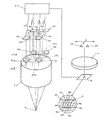
図1は本発明による実体顕微鏡の第1実施例の全体構成を示す図である。図中、0は物体、1は物体0からの光束をアフォーカル光束にする対物レンズ、2は各光軸が同一面内にあるように配置された三組のアフォーカル変倍レンズ、3は各アフォーカル変倍レンズ2の光軸上に配置された結像レンズで、これら三組の光学系は、対物レンズ1を射出した光束を左側光束と中央光束と右側光束とに分ける役割を果たしていて、各倍率は略等しくなるように設計されている。4L,4M,4Rは左側光束,中央光束,右側光束の各結像面に設置された撮像素子、5L,5M,5Rは左側撮像素子4L,中央撮像素子4M,右側撮像素子4Rに夫々接続された撮像データ処理回路、6L,6M,6Rは各撮像データ処理回路5L,5M,5Rに夫々接続された画像表示装置、7L,7M,7Rは各画像表示装置6L,6M,6Rに対応するように配置されたコリメータレンズ、8L,8Rは左側コリメータレンズ7Lと右側コリメータレンズ7Rに夫々対応して配置され各射出面が開口絞り(瞳と共役の位置)になるように設計された合成プリズム、9は表示光学系結像レンズ、10は結像点、11は左右共通の接眼レンズ、12L,12Rは観察者の左右の目である。
【0007】
第1実施例は上記のように構成されているから、物体0から発した光束は、対物レンズ1によりアフォーカルな光束にされ、三組のアフォーカルレンズ2と結像レンズ3により左側光束と中央光束と右側光束とに分割されて、左側撮像素子4Lと中央撮像素子4Mと右側撮像素子4R上に夫々結像される。各撮像素子4L,4M,4Rからの撮像データは、各撮像データ処理回路5L,5M,5Rに送られ、ホワイトバランス等必要な画像処理を施された後に各画像表示装置6L,6M,6Rに送られ、夫々の像を表示する。かくして表示された各像は、コリメータレンズ7R,7M,7Lにより夫々アフォーカル光束にされ、合成プリズム8R,8Lにより合成されて、表示光学系結像レンズ9により結像点10に結像され、この像は接眼レンズ11により拡大観察される。この場合、目を紙面内で中央光束の光軸に垂直な方向(矢印方向)に動かすことにより、三方向の像を観察することが出来る。この三方向の像の内二つを左右それぞれの目で見れば、立体観察が可能である。
【0008】
この実施例によれば、各結像光学系の光軸が物体付近で同一平面内にあり、接眼光学系の各画像の対応する光軸が観察者の覗く位置でも同一平面内であり、撮影光学系の観察方向と接眼光学系の覗く位置とが対応するように構成されているから、一般的な実体顕微鏡のように眼幅調整の必要がなく、従って目の位置の制限が減り、より自由な姿勢で観察することが出来る。また、融像による立体視が出来ない人でも、覗く位置を変えることで観察方向が変えられることを利用して、立体的な把握の手助けが出来る。また、観察方向を変更することが出来るので、障害物を避けて目的の対象物を観察できると云う利点もある。また、撮影光学系の鏡体と表示光学系の鏡筒とは電気的に連結されているだけであるから、作業者の覗き易い位置に配置することができると云う利点もある。更に、物体面への作業が遠隔操作で出来る場合、観察者も対象物から離れて作業できると云う利点がある。
【0009】
実施例2
図2は本発明による実体顕微鏡の第2実施例の全体構成を示す図である。図中13は可変作動距離対物レンズ(この対物レンズは、作動距離を変えるためにレンズ系の一部を動かすことができ、これにより鏡体全体を動かさずに焦点合わせが出来るので作業位置が前後に変わる対象物には有利に使用することができ、以下可変WD対物レンズと云う)。14は可変WD対物レンズ13と同軸のアフォーカル変倍系、15a,15b,15c,15d,15eは分割された光束の同一の平面内にある五本の光軸上に夫々配置された結像レンズ、16a,16b,16c,16d,16eは結像レンズ15a,15b,15c,15d,15eの各結像点に配置された撮像素子、17は各撮像素子16a,16b,16c,16d,16eで得られた画像データを処理する電気処理回路、18は表示画素の近くにレンチキュラーレンズ19が設置されていて曲面がある方向に目を動かすと見える像が変わるように構成されたレンチキュラー表示素子、20a,20b,20c,20d,20eはレンチキュラーレンズ19の一つの曲面に対応してその曲面の焦点位置に結像するように配置された表示画素、21はレンチキュラー表示素子18を観察するための接眼レンズである。結像レンズ15a,15b,15c,15d,15eは、各レンズの開口が瞳位置で光束を分割し、各光束は物体面で一致せしめられるようになっている。なお、表示画素20a,20b,20c,20d,20eは、観察者が左に見る位置を変えると物体側で左の画像が見えるように配置されている。
【0010】
第2実施例は上記のように構成されているから、物体0から発した光束は、可変WD対物レンズ13とアフォーカル変倍系14を透過してアフォーカル光束にされ、結像レンズ15a,15b,15c,15d,15eにより五つの光束に分割されて、対応する撮像素子16a,16b,16c,16d,16e上に夫々結像せしめられる。かくして得られた五つの撮像データは電気処理回路17で処理され、この処理データはレンチキュラー表示素子18へ送られて画像として表示され、その画像は接眼レンズ21により拡大観察される。
【0011】
この実施例では、観察者の目12L,12Rをレンチキュラー19の曲面のある方向に動かした場合、左目12Lが表示画面20bを、右眼12Rが表示画素20dを見るようにすると使用感は良い。人が接眼レンズ21のように一つのレンズを覗く場合中央に頭を置くので、表示画素20bが作る瞳の範囲と表示画素20dが作る瞳の範囲に、眼幅の大きい人も眼幅の小さい人も入る。従って、表示画素の一つの瞳位置で占める範囲が最小眼幅の人よりも小さく、表示画素三つ分の瞳位置で占める範囲が最大眼幅の人より大きいことが必要条件である。表示画素のレンチキュラーレンズ19の曲面の方向の間隔をD、レンチキュラーレンズ19の曲面の焦点距離をfr、接眼レンズ21の焦点距離をfとしたとき、25≦D×(f/fr)≦55なる条件を満足すると良い。しかし、この場合、眼幅最大の人や最小の人は少し頭を動かすだけで観察像が変わるので疲れ易くなる。これを避けるため、片側で5mmの余裕をとれば良いので、35≦D×(f/fr)≦45なる条件を満足するようにすると、より良い観察が可能となる。
【0012】
また、この実施例では、アフォーカル変倍系14で変倍すると観察範囲が倍率に比例して大きくなるが、視差が小さくて画像が立体的に見えなくなったり、視差が大きくなり過ぎて融像ができなくなったりしない範囲で変倍するのが良い。この実施例は、第1実施例に比べて、変倍部の変更が少なく、倍率による観察像の差が発生しにくく、而も観察し易い実体顕微鏡を作り易いと云う利点がある。また、像をより自然に見せるため光束の分割数を増やすことも可能である。また、本実施例によれば、覗く位置を変えることで観察方向が変えられることを利用して立体的な把握の手助けができ、障害物を避けて目的の対象物を観察できる効果が第1実施例の場合よりも大きい。
【0013】
この実施例においても、第1実施例と同様、撮影光学系が三つ以上の結像光学系から成っていて、各結像光学系の光軸が物体付近で同一平面内にあり、接眼光学系の各画像の対応する光軸も観察者の覗く位置において同一平面内にあって、撮影光学系の観察方向と接眼光学系の覗く位置とが対応するように構成されている。この撮影光学系は、焦点合わせと、変倍と、撮影面に結像させる機能とを持っている。そして左右の焦点合わせは、各撮影光学系の光束を総て透過させる対物レンズ13を設けて、この対物レンズ全体または構成レンズの一部を動かすことにより行うようになっているため、撮影光学系を支持するスタンドに微動機構を設ける必要がなくなり、架台を軽量化することが出来る。また、変倍レンズも各像に共通の一つの変倍系を用いているので、変倍時の像の左右差を減らすことが出来る。また、画像表示手段としてレンチキュラー表示素子を用いたので、表示装置を小型に構成することが出来る。
【0014】
実施例3
図3は本発明による実体顕微鏡の第3実施例の全体構成を示す図である。図中、22は物体0からの光束をアフォーカル光束で射出することができ、構成レンズの一部を動かすか又は構成レンズの交換、挿脱、変形などにより物体0までの距離や倍率を変えることが出来る対物光学系、23a,23c,23g,23iは各開口絞りの中心を通る光軸を結ぶ形状が長方形になるように各開口に合わせて配置された結像レンズ、23b,23d,23e,23f,23hは結像レンズ23a,23c,23g,23iの各中間位置に配置された結像レンズ、24a,24b,24c,24d,24e,24f,24g,24h,24iは結像レンズ23a,23b,23c,23d,23e,23f,23g,23h,23iの結像点に夫々配置された撮像素子、25は撮像素子24a,24b,24c,24d,24e,24f,24g,24h,24iで撮影された各画像データを受けてホワイトバランスなどの画像処理を加える電気処理回路、26は一つの絵素(表示画素)が一つのマイクロレンズ27と九つの表示画素28a,28b,28c,28d,28e,28f,28g,28h,28iとから成り一つのマイクロレンズ27で九つの表示画素28a,28b,28c,28d,28e,28f,28g,28h,28iの光束を各方向へ射出し得るマイクロレンズ表示装置、29は接眼レンズである。なお、マイクロレンズ表示装置26により表示される画像は接眼レンズ29を介して観察者が覗く位置を変えると、同じ方向から見た物体0の画像が見られるように配置されている。
【0015】
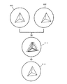
第3実施例は上記のように構成されているから、物体0から発した光束は、対物レンズ系22でアフォーカルな光束にされ、各結像レンズ23a,23b,23c,23d,23e,23f,23g,23h,23iを介して各撮像素子24a,24b,24c,24d,24e,24f,24g,24h,24i上に結像される。今、図3に示すように四つの結像レンズ23a,23c,23g,23iと、対応する四つの撮像素子24a,24c,24g,24iが使用されているものとすると、電気処理回路25ではホワイトバランスなどの画像処理に加えて撮像素子24a,24c,24g,24iで撮影された中間の視差の画像が作られる。この場合、二つの画像が多少視差の違う像であれば二つの画像の対応点は取り易く、その対応点の中間にその点が来ると云う方法で中間像が作られる。これを図4を参照して説明する。撮影された左目用画像60Lと右目用画像60Rを重ねると、合成画像61のようになる。この合成画像61の内一点鎖線図示のものが左目の画像であり、破線図示のものが右目画像であるが、これらの画像の中間点をとると、実線図示の画像となる。この実線図示の画像が中間画像62となる。かくして得られる中間画像62は、結像レンズ23a,23c,23g,23iの各中間位置に結像レンズ23b,23d,23e,23f,23h(破線図示)を配置し、これに対応して撮像素子24a,24c,24g,24iの各中間位置に配置される撮像素子24b,24d,24e,24f,24h(破線図示)により夫々撮影されて得られる画像と同じである。電気処理回路25において、このようにして得られた画像データは、マイクロレンズ表示装置26により表示されるべきデータに変換され、マイクロレンズ表示装置26へ転送される。マイクロレンズ表示装置26により表示された画像は接眼レンズ29により拡大して観察される。
【0016】
この実施例によれば、上記説明から明らかなように、中間像を作って分割数を増やすことにより、比較的少数の撮像光学系を用いても、接眼レンズを介して実際に観察物体を見ているような状態に近付けることが出来る。また、第1実施例及び第2実施例では目を動かして像の変わる方向が一次元であったのに対して、本実施例では、目を二次元的に動かしても像が変わると云う特徴を有する。従って、障害物を避けて観察するのには有効であり、また、直角方向から観察しても立体的に像を見ることができる。また、複数の観察者による観察にも対応することが出来る。
【0017】
実施例4
図5は本発明による実体顕微鏡の第4実施例の全体構成を示す図である。図中30は物体0からの光束をアフォーカル光束にする対物レンズ、31は対物レンズ30と同軸のアフォーカル変倍系、32はアフォーカル変倍系31の射出光軸に対し垂直な平面内で動くことができ左右一体の結像レンズ33L,33Rと該結像レンズ33L,33Rの各結像点に配置されたCCDなどの撮像素子34L,34Rとを内蔵した撮影鏡筒、35は撮像素子34L,34Rに接続された電気処理回路、36は電気処理回路35の出力端に接続されていて交互に並べられた複数の右目用表示素子38R及び左目用表示素子38Lと、隣接する一対の右目用表示素子38Rと左目用表示素子38L上に焦点が来るように配置されたレンチキラーレンズ37とを含む表示素子、39は表示装置36上に表示された像を拡大観察するための接眼レンズ、40は接眼レンズ39に隣接配置された光源、41は接眼レンズ39に隣接して配置されていて観察者の目12L,12Rによる光源40からの反射光を集光する集光レンズ42と集光された前記反射光を受光する位置センサー43とを含む目位置検出系、44は位置センサー43の出力による目の動きに従って撮影鏡筒32の移動を制御する制御回路である。なお、レンチキュラーレンズ37の隣接する曲面間の間隔は、右目用表示素子38Rと左目用表示素子38Lとを合わせた長さと略等しくなるように設計されている。
【0018】
本実施例は上記のように構成されているから、物体0から発した光束は対物レンズ30及びアフォーカル変倍系31を透過して撮影鏡筒32より撮影され、この撮影された像は電気処理回路35において表示装置36で観察できるように処理されて、表示装置36へ送られる。かくして表示装置36により表示された画像は接眼レンズ39により拡大して観察される。この場合、撮影鏡筒32は、目位置検出系41と制御回路44を介し目の動きに従って動かされる。
【0019】
本実施例では、観察者の目の位置の検出を二次元的に行うことにより、第1実施例や第2実施例とは異なり、左右の目を結ぶ方向(左右方向)だけでなく、この方向に対し垂直の方向にも撮影鏡筒32を動かすことが出来る。また、既述の実施例では、目の動きに対する物体側の方向の変化は一定であるのに対して、本実施例では制御回路44に目の動きに対する撮影鏡筒32の動きの比を適誼設定することにより、観察者の使い勝手の良いようにすることが出来る。また、アフォーカル変倍系31の倍率に比例して観察者の目の動きに対する物体側の観察方向の動きは大きくなるが、制御回路44により、物体側の倍率変化に対する観察方向の変化を小さくするように処理することが出来る。アフォーカル変倍系31の倍率がβ1からβ2に変化したとき、目の移動量に対する撮影鏡筒32の移動量の比がK1からK2に変化したとすると、K2=K1×(β1/β2)なる関係がある。
【0020】
この場合、立体感も同様に変化するので、立体感を一定に保つために、左右の光軸間隔を変えるようにすれば良く、こうすることにより倍率範囲を広げることが出来る。即ち、上記式においてK1,K2を光軸間隔とし、それに連動して倍率を変化させるようにすれば良い。しかし、これは、物体側の立体角(左右の光軸のなす角)が1度から15度の間であれば多くの人の場合問題ない。立体角が小さいと立体感が小さくて立体的に見えず、大き過ぎると融像できないためである。この立体角の範囲での変倍であれば、撮影鏡筒32の光軸の間隔を変えなくても問題はない。また、特に自然に見るためには立体角は2度から10度の間であると良い。
【0021】
また、アフォーカル変倍系31と撮影鏡筒32の間にビームスプリッターを入れることにより光学像を観察することが出来るような鏡筒を用いれば、同一倍率の光学像を簡単に得ることができ、電気系の故障時に対応させることが出来る。また、第1及び第2実施例を左右方向の像作成に用い、上下方向の像作成にのみ本実施を用いるようにすることにより、左右の像の視差以外のズレを小さくすることができ且つ調整の簡単な光学系を得ることが出来る。また、表示光学系は左右方向に5mm移動することができるようにすれば、目を左右に振ることにより像の観察方向が変わる効果が出て来る。眼幅は75mmあれば殆どの人をカバーできるので、表示幅で80mm以上あれば良い。
【0022】
実施例5
図6は本発明による実体顕微鏡の第5実施例の全体構成を示す図である。図中45は物体0からの光束をアフォーカル光束にする可変WD対物レンズ、46は可変WD対物レンズ45の光軸に対し垂直な面内で移動可能に構成されていて、左右一対のアフォーカル変倍系47L,47Rと一対の結像レンズ48L,48Rと一対の撮影系49L,49Rを内蔵した撮影鏡筒,50L,50Rは撮影系49L,49Rに夫々接続されていて撮影鏡筒46で撮影したデータを処理する左右の電気処理回路、51L,51Rは電気処理回路50L,50Rの各出力端に接続された左右の画像表示装置、52L,52Rは画像表示装置51L,51Rに表示された画像を拡大観察するための左右一対の接眼レンズ、53は接眼レンズ52Lと52Rの中間に配置された光源、54L,54Rは接眼レンズ52L,52Rに夫々隣接配置されている光源53から出射して観察者の左右の目12L,12Rで夫々反射した光を集光するための集光レンズ、55L,55Rは集光レンズ54L,54Rで集光された光を夫々受光する位置センサー、56は位置センサー55L,55Rの各出力端に接続されていて位置センサー55L,55Rからの出力に応じて撮影鏡筒46の位置を制御することの出来る制御回路である。
【0023】
本実施例は上記のように構成されているから、物体0から発した光束は、可変WD対物レンズ45によりアフォーカルな光束にされ、撮影鏡筒46により左右の目で観察されるべき像が撮影される。撮影鏡筒46で撮影された像データは電気処理回路50L,50Rにより夫々処理され、左右の画像表示装置51L,51R上に画像として表示される。これらの画像は左右一対の接眼レンズ52L,52Rを介して観察者により拡大観察される。この場合、光源53から発した光は、観察者の左右の目12L,12Rにより反射され、夫々集光レンズ54L,54Rを介して位置センサー55L,55Rに達する。かくして各位置センサー55L,55Rからの出力は制御回路56で処理されて撮影鏡筒46の駆動装置へ出力され、その結果、撮影鏡筒46は観察者の目12L,12Rの位置に連動して同じ方向に動かされる。
【0024】
この実施例では、アフォーカル変倍系47L,47Rと結像レンズ48L,48Rは分離しなくても良いが、撮影系49L,49RとしてCCDなど種々の撮像面積を有する撮影素子があるので、それに対応するのに結像レンズのみの変更で済むようにするため実施例のような構成にするのが良い。また、光源53としては、作業に気にならないように目に見えない赤外光を使用すると云う意味で、赤外ランプを用いるのが良い。また、本実施例の場合、目の移動に対する物体の観察方向の変化は、第4実施例とは異なり倍率によらず一定である。また、接眼レンズ52L,52Rの射出瞳は、左右の瞳間隔を65mmにして、直径10mm以上であると眼幅調整が不要になり、目の移動による効果が感じられるのは瞳径が15mm以上の場合である。瞳径が20mm以上になると、目の移動による物体側の変化を細かく調整できるようになり使い易くなる。
【0025】
実施例6
図7は本発明による実体顕微鏡の第6実施例の全体構成を示す図である。図中、63は物体0からの光束をアフォーカル光束で射出することができ構成レンズの一部を動かすか又は構成レンズの交換、挿脱、変更などにより物体0までの距離や倍率を変えることが出来る対物光学系、64a,64b,64c,64dは対物光学系63の後に各開口絞りの中心を通る光軸を結ぶ形状が長方形になるように各開口に合わせて配置された結像レンズ、65a,65b,65c,65dは結像レンズ64a,64b,64c,64dの結像点に夫々配置された撮像素子、66L,66Rは結像レンズ64a,64b,64c,64dと同様に構成配置された左右の仮想結像レンズ、67L,67Rは仮想結像レンズ66L,66Rの結像点に夫々配置された仮想撮像素子、68は撮像素子65a,65b,65c,65dで撮影された各画像データを受けてホワイトバランスなどの画像処理を加えて各撮像素子65a,65b,65c,65dで撮影した中間の視差のある二つの画像を作る電気処理回路、69L,69Rは電気処理回路68の出力端に接続されていてここで作られた画像を表示するための左右の画像表示装置、70L,70Rは画像表示装置69L,69Rに表示された画像を拡大観察するための左右の接眼レンズ、71は接眼レンズ70L,70Rの中間に配置された好ましくは赤外ランプ等の光源、72L,72Rは接眼レンズ70L,70Rに夫々隣接配置されていて光源71から出射して観察者の左右の目12L,12Rで夫々反射した光を集光するための集光レンズ、73L,73Rは集光レンズ72L,72Rで集光された光を夫々受光する位置センサー、74は位置センサー73L,73Rの各出力端に接続されていて位置センサー73L,73Rからの出力を電気処理回路68へ入力させる検出回路、75は左右の仮想結像レンズ66L,66Rと仮想撮像素子67L,67Rとを含む仮想鏡筒(破線図示)である。
【0026】
本実施例は上記のように構成されているから、物体0から発した光束は対物光学系63でアフォーカルな光束にされ、各結像レンズ64a,64b,64c,64dを介して各撮像素子65a,65b,65c,65d上に結像される。電気処理回路68は各撮像素子65a,65b,65c,65dから入力した各画像信号に基づき視差のある二つの画像信号を作成し、これを出力して画像表示手段69L,69Rに夫々左右視差のある画像を表示させる。この画像は接眼レンズ70L,70Rを介して拡大観察される。この場合の画像は、仮想鏡筒75を介して得られる画像と同じであり、この画像を作る位置は観察者の覗いている位置に対応するようにされる。観察中、光源71を発した光は観察者の左右の目12L,12Rで夫々反射され、各反射光は集光レンズ72L,72Rを介して位置センサー73L,73Rにより感知され、検出回路74で処理される。かくして得られた位置情報は電気処理回路68に入力され、ここで、目の位置に連動して同じ方向に仮想鏡筒75を動かしたのと同じ画像信号が作成される。これにより、接眼レンズ70L,70Rを覗く位置を変えると、物体を見る方向が変えられる。なお、撮像素子65a,65b,65c,65dで撮影した中間の視差のある二つの画像を作る場合、得られた四つの画像が多少視差の違う像であれば各画像の対応点は取り易く、その対応点の特定の比でその点を取ると云う方法で中間像を作れば良い。
【0027】
この実施例は、動く部分が少ないので故障しにくいと云う特徴を有し、また、中間像を作る場合目の動きと物体の撮影方向の比を設定することにより、頭の移動に対する像の方向変化を観察者の好みに合わせることが出来ると云う利点がある。また、画像の立体感は仮想結像レンズ66L,66Rの光軸間隔で決まるので、画像を作成する場合この光軸間隔を変えることにより立体感を調整することが出来る。
【0028】
以上実施例では何れも実体顕微鏡を対象に説明したが、本発明は、立体内視鏡装置や双眼鏡装置など撮影系と撮影した画像を表示する接眼光学系を備えた各種の立体観察装置に適用することが出来る。
【0029】
以上説明したように、本発明による実体顕微鏡は、特許請求の範囲に記載した特徴のほか下記の特徴も有する。
【0030】
(1)前記撮影光学系が三つ以上の結像光学系から成っていて各結像光学系の光軸が物体付近で同一平面上にあり、接眼光学系の各画像の光軸が観察者の覗く位置でも同一平面であり、前記撮影光学系の観察方向と接眼光学系の覗く位置が対応するように構成したことを特徴とする請求項1に記載の実体顕微鏡。
【0031】
(2)前記撮影光学系が四つの撮影光学系から成り、各撮影光学系の光軸を結ぶ形状が長方形になり、その撮影画像の間の視差の画像を作って、観察者が目を動かした時の像と同方向の画像が見られるように表示することを特徴とする請求項1に記載の実体顕微鏡。
【0032】
(3)撮影光学系が少なくとも一対の結像光学系を含み、接眼光学系は観察者の目の位置を検出する手段を有していて、観察者の目の位置に対応して前記一対の結像光学系を動かして観察方向を変えることが出来るようにしたことを特徴とする請求項1に記載の実体顕微鏡。
【0033】
(4)撮影光学系が三つ以上の互いに分離された撮影光束を含む一つの対物レンズを含み、前記各光束中に連動して変倍を行い得る変倍系を夫々設けたことを特徴とする上記(1)に記載の実体顕微鏡。
【0034】
(5)撮影光学系が、物体からの光束をアフォーカル光束にする一つの対物レンズと、該対物レンズと同軸の一つのアフォーカル変倍光学系と、該アフォーカル変倍系の光軸を含む面内に光軸のある三つの結像光学系とを備えていることを特徴とする上記(1)に記載の実体顕微鏡。
【0035】
(6)撮影光学系の撮影画像と同数の画像表示手段を有し、該画像表示手段に表示された各画像を接眼光学系の入射瞳位置に一致させ、該接眼光学系の射出瞳位置に前記各画像の投影光学系の瞳が横に並び且つ物体を見る方向と一致するようにしたことを特徴とする上記(1)に記載の実体顕微鏡。
【0036】
(7)接眼光学系に、マイクロレンズの焦点位置に画像表示素子が二次元的に配置された画像表示装置を用いたことを特徴とする上記(2)に記載の実体顕微鏡。
【0037】
(8)接眼光学系に、目の位置を検出してその位置情報から左右の像を作りその像を左右の目で観察できるようにする手段を設けたことを特徴とする上記(2)に記載の実体顕微鏡。
【0038】
(9)撮影光学系が、対物レンズと該対物レンズと同軸の一つのアフォーカル変倍系とを更に含み、一対の結像光学系の光軸間隔が変えられるようになっていることを特徴とする上記(3)に記載の実体顕微鏡。
【0039】
(10)接眼光学系が左右一対の接眼レンズを含み、該一対の接眼レンズの射出瞳径が夫々15mm以上であることを特徴とする上記(3)に記載の実体顕微鏡。
【0040】
【発明の効果】
上述の如く本発明によれば、観察者が顕微鏡を動かすことなしに観察方向を変えることができ、その結果障害物により見えない部分を顕微鏡を動かすことなしに見えるようにすることが出来る、便利な実体顕微鏡を提供することが出来る。また、本発明によれば、目の動きに従って像が動くので、両眼視差に加えて運動視差が得られ、観察物体の三次元的な把握が容易な実体顕微鏡を提供することが出来る。
【図面の簡単な説明】
【図1】本発明の第1実施例の全体構成を示す図である。
【図2】本発明の第2実施例の全体構成を示す図である。
【図3】本発明の第3実施例の全体構成を示す図である。
【図4】第3実施例において中間画像を作る方法を示す図である。
【図5】本発明の第4実施例の全体構成を示す図である。
【図6】本発明の第5実施例の全体構成を示す図である。
【図7】本発明の第6実施例の全体構成を示す図である。
【図8】実体顕微鏡の従来例の斜視図である。
【図9】従来の実体顕微鏡に用いられている光学系の全体構成の一例を示す図である。
【符号の説明】
0 物体
1,13,30,45 対物レンズ
2 アフォーカル変倍レンズ
3,15a〜15d,23a〜23i,33L,33R,48L,48R,64a〜64d,66L,66R 結像レンズ
4L,4R,4M,16a〜16e,24a,24i,34L,34R,65a〜65d,67L,67R 撮像素子
5L,5M,5R 撮像データ処理回路
17,25,35,50L,50R,68 電気処理回路
6L,6M,6R,51L,51R,69L,69R 画像表示装置
7L,7M,7R コリメータレンズ
8L,8R 合成プリズム
9 表示光学系結像レンズ
10 結像点
11,21,29,39,52L,52R,70L,70R 接眼レンズ
12L,12R 観察者の目
14,31,47L,47R アフォーカル変倍系
18 レンチキュラー表示素子
19 レンチキュラーレンズ
20a〜20e,28a〜28i 表示画素
22,63 対物光学系
26 マイクロレンズ表示装置
27 マイクロレンズ
32,46,75 撮影鏡筒
37 レンチキュラーレンズ
38L,38R 表示素子
40,53,71 光源
41 目位置検出系
42,54L,54R,72L,72R 集光レンズ
43,55L,55R,73L,73R 位置センサー
44,56 制御回路
49L,49R 撮影系
74 検出回路
75 仮想鏡筒[0001]
[Technical field to which the invention belongs]
The present invention relates to an optical apparatus such as a stereomicroscope and a stereoscopic endoscope that can stereoscopically observe an image of an object.
[0002]
[Prior art]
A stereomicroscope is a device that magnifies a small object and views it stereoscopically. By using this, it contributes to increasing the success rate of surgery using precision work, especially surgery. In order to perform precise work, the magnification is high, and it is required to see the object from various directions. To change the viewing direction greatly, it is only necessary to move the stereomicroscope. For example, as shown in FIG. 8 (Japanese Patent Laid-Open No. 63-296746), a stand has been devised to change the viewing direction by fixing one point. Yes. As a result, the viewing direction can be changed when the observation object cannot be sufficiently viewed by an obstacle (for example, a blood vessel not related to a working device or an operation part) before the observation object. However, in this example, even if you change the direction slightly, you will be operating a foot switch that moves the mirror using your feet, which increases the burden on the operator and does not reduce fatigue was there. Further, as shown in FIG. 9 (Japanese Patent Application Laid-Open No. 5-107481), a method has been conceived in which an exit pupil diameter larger than the eye width is created by using a single stereomicroscope optical system. However, in this optical system, when the magnification is increased, the exit pupil diameter is reduced. Therefore, the magnification is increased only about 5 times, and it is difficult to realize the magnification of 5 times or more required by the operator. Further, as disclosed in Japanese Patent Application Laid-Open No. 8-304707, a method of putting a diffuser plate in the focal plane and a method of taking two images with parallax, displaying them on a monitor, and magnifying them are also considered. However, it does not change the observation direction on the object side simply by increasing the exit pupil diameter to make it easier to look into.
[0003]
In addition, the stereoscopic microscope gives an image based on binocular parallax and grasps an observation object in three dimensions, but there are people who cannot grasp the three-dimensional figure from the image based on binocular parallax. These persons are persons who have a large difference in visual acuity between the left and right eyes, and who have not mastered stereoscopic grasping with binocular parallax. In many cases, such a person grasps in a three-dimensional manner by observing the object in a slightly different direction. These people want a stereomicroscope that moves their heads and changes the viewing direction on the object side.
[0004]
[Problems to be solved by the invention]
The present invention has been made in view of the conventional problems as described above, and an object of the present invention is to provide a stereomicroscope in which the observation direction on the object side changes according to the movement of the observer's head. .
[0005]
[Means for Solving the Problems]
In order to achieve the above object, a stereomicroscope according to the present invention includes an imaging optical system that captures an image with left and right parallax, and an eyepiece optical system that displays the image on an image display means and observes with the left and right eyes. The stereomicroscope is characterized in that images of the same magnification can be observed by changing the direction of observation on the object side by moving the observer's eye in a plane perpendicular to the optical axis.
In the stereomicroscope according to the present invention, the imaging optical system includes three or more imaging optical systems, and the optical axes of the imaging optical systems are on the same plane near the object. The optical axis is the same plane even when viewed by an observer, and the observation direction of the photographing optical system and the position of the eyepiece optical system correspond to each other.
Further, in the stereomicroscope according to the present invention, the photographing optical system is composed of four photographing optical systems, the shape connecting the optical axes of the photographing optical systems is rectangular, and a parallax image between the photographed images is created, It is characterized by displaying so that an image in the same direction as the image when the observer moves his eyes can be seen.
Further, in the stereomicroscope according to the present invention, the photographing optical system includes at least a pair of imaging optical systems, and the eyepiece optical system has a means for detecting the position of the observer's eyes. Correspondingly, the viewing direction can be changed by moving the pair of imaging optical systems.
In addition, the stereomicroscope according to the present invention includes a zooming system in which the shooting optical system includes three or more objective lenses including shooting light beams separated from each other and can perform zooming in conjunction with each of the light beams. It is characterized by providing.
In addition, the stereomicroscope according to the present invention includes an objective lens that converts a light beam from an object into an afocal beam, a single afocal variable magnification optical system that is coaxial with the objective lens, and the afocal lens. And three imaging optical systems having an optical axis in a plane including the optical axis of the double system.
In addition, the stereomicroscope according to the present invention has the same number of image display means as the number of images taken by the photographing optical system, and matches each image displayed on the image display means with the entrance pupil position of the eyepiece optical system. It is characterized in that the pupils of the projection optical system of each image are aligned horizontally at the exit pupil position of the system and coincide with the direction of viewing the object.
The stereomicroscope according to the present invention is characterized in that an image display device in which an image display element is two-dimensionally arranged at the focal position of a microlens is used as an eyepiece optical system.
In addition, the stereomicroscope according to the present invention is characterized in that the eyepiece optical system is provided with means for detecting the position of the eyes and creating left and right images from the position information so that the images can be observed with the left and right eyes. Yes.
In the stereomicroscope according to the present invention, the photographing optical system further includes an objective lens and a single afocal variable magnification system coaxial with the objective lens so that the optical axis interval of the pair of imaging optical systems can be changed. It is characterized by becoming.
Furthermore, the stereomicroscope according to the present invention is characterized in that the eyepiece optical system includes a pair of left and right eyepiece lenses, and the exit pupil diameter of each of the pair of eyepiece lenses is 15 mm or more.
[0006]
DETAILED DESCRIPTION OF THE INVENTION
Hereinafter, embodiments of the present invention will be described based on illustrated examples.
Example 1
FIG. 1 is a diagram showing an overall configuration of a first embodiment of a stereomicroscope according to the present invention. In the figure, 0 is an object, 1 is an objective lens that converts a light beam from the
[0007]
Since the first embodiment is configured as described above, the light beam emitted from the
[0008]
According to this embodiment, the optical axis of each imaging optical system is in the same plane in the vicinity of the object, and the corresponding optical axis of each image in the eyepiece optical system is also in the same plane even at the position where the observer peeks. Since the observation direction of the optical system and the viewing position of the eyepiece optical system correspond to each other, there is no need to adjust the eye width as in a general stereomicroscope, thus reducing the restriction on the position of the eye. It can be observed in any posture. Further, even a person who cannot perform stereoscopic viewing by fusion can assist in grasping a stereoscopic view by utilizing the fact that the observation direction can be changed by changing the peeping position. In addition, since the observation direction can be changed, there is an advantage that a target object can be observed while avoiding an obstacle. Further, since the lens body of the photographing optical system and the lens barrel of the display optical system are merely electrically connected, there is an advantage that it can be arranged at a position where the operator can easily look into. Furthermore, when the work on the object surface can be performed remotely, there is an advantage that the observer can work away from the object.
[0009]
Example 2
FIG. 2 is a diagram showing the overall configuration of a second embodiment of the stereomicroscope according to the present invention. In the figure, reference numeral 13 denotes a variable working distance objective lens (this objective lens can move a part of the lens system in order to change the working distance, so that focusing can be performed without moving the entire body, so that the working position can be moved back and forth. It can be advantageously used for objects that change to the following, and is hereinafter referred to as a variable WD objective lens). Reference numeral 14 denotes an afocal variable magnification system that is coaxial with the variable WD
[0010]
Since the second embodiment is configured as described above, the light beam emitted from the
[0011]
In this embodiment, when the observer's
[0012]
In this embodiment, when the magnification is changed by the afocal zooming system 14, the observation range is increased in proportion to the magnification. However, the parallax is small and the image cannot be viewed stereoscopically, or the parallax becomes too large and the fusion is performed. It is better to change the magnification as long as you can not. Compared with the first embodiment, this embodiment has the advantage that the change of the zooming portion is less, the difference in the observation image due to the magnification hardly occurs, and a stereomicroscope that is easy to observe can be easily made. It is also possible to increase the number of light beam divisions in order to make the image appear more natural. In addition, according to the present embodiment, it is possible to assist in three-dimensional grasping by utilizing the fact that the observation direction can be changed by changing the peeping position, and the first effect is that the target object can be observed while avoiding obstacles. It is larger than the case of the embodiment.
[0013]
In this embodiment, as in the first embodiment, the photographing optical system is composed of three or more imaging optical systems, and the optical axes of the imaging optical systems are in the same plane near the object. The corresponding optical axis of each image in the system is also in the same plane at the position where the observer looks, and the observation direction of the photographing optical system and the position where the eyepiece optical system looks are configured to correspond to each other. This photographing optical system has functions of focusing, zooming, and forming an image on a photographing surface. The left and right focusing is performed by providing an objective lens 13 that transmits all the light beams of each photographing optical system and moving the entire objective lens or a part of the constituent lenses. It is not necessary to provide a fine movement mechanism on the stand that supports the frame, and the weight of the gantry can be reduced. Further, since the variable magnification lens also uses a single variable magnification system common to each image, the left-right difference of the image at the time of variable magnification can be reduced. Further, since the lenticular display element is used as the image display means, the display device can be made compact.
[0014]
Example 3
FIG. 3 is a diagram showing the overall configuration of a third embodiment of the stereomicroscope according to the present invention. In the figure,
[0015]
Since the third embodiment is configured as described above, the light beam emitted from the
[0016]
According to this embodiment, as is clear from the above description, an intermediate image is formed and the number of divisions is increased, so that even when a relatively small number of imaging optical systems are used, the observation object is actually viewed through the eyepiece. You can get closer to the state. In addition, in the first and second embodiments, the direction in which the image changes when the eyes are moved is one-dimensional, but in this embodiment, the image changes even if the eyes are moved two-dimensionally. Has characteristics. Therefore, it is effective for observing while avoiding obstacles, and a three-dimensional image can be seen even when viewed from a right angle direction. Moreover, it can respond to observation by a plurality of observers.
[0017]
Example 4
FIG. 5 is a diagram showing the overall configuration of a fourth embodiment of a stereomicroscope according to the present invention. In the figure, 30 is an objective lens that converts the light beam from the
[0018]
Since the present embodiment is configured as described above, the light beam emitted from the
[0019]
In the present embodiment, the position of the observer's eyes is detected two-dimensionally, so that unlike the first and second embodiments, not only the direction of connecting the left and right eyes (left and right direction), but also this The
[0020]
In this case, the stereoscopic effect changes in the same manner. Therefore, in order to keep the stereoscopic effect constant, the distance between the left and right optical axes may be changed, and the magnification range can be widened. That is, in the above equation, K1 and K2 may be set as the optical axis interval, and the magnification may be changed in conjunction therewith. However, this is not a problem for many people if the solid angle on the object side (angle formed by the left and right optical axes) is between 1 and 15 degrees. This is because if the solid angle is small, the stereoscopic effect is small and it does not look three-dimensional, and if it is too large, it cannot be fused. As long as the magnification is varied within the range of the solid angle, there is no problem even if the interval between the optical axes of the imaging barrels 32 is not changed. Moreover, in order to see naturally especially, it is good that the solid angle is between 2 degrees and 10 degrees.
[0021]
If a lens barrel that can observe an optical image by inserting a beam splitter between the afocal zoom system 31 and the
[0022]
Example 5
FIG. 6 is a diagram showing an overall configuration of a fifth embodiment of the stereomicroscope according to the present invention. In the figure, 45 is a variable WD objective lens that converts the light beam from the
[0023]
Since the present embodiment is configured as described above, the light beam emitted from the
[0024]
In this embodiment, the
[0025]
Example 6
FIG. 7 is a diagram showing the overall configuration of a sixth embodiment of the stereomicroscope according to the present invention. In the figure,
[0026]
Since the present embodiment is configured as described above, the light beam emitted from the
[0027]
This embodiment has a feature that it is difficult to break down because there are few moving parts, and in the case of creating an intermediate image, the direction of the image with respect to the movement of the head is set by setting the ratio of the eye movement to the shooting direction of the object. There is an advantage that the change can be adapted to the preference of the observer. In addition, since the stereoscopic effect of the image is determined by the optical axis interval of the
[0028]
In the above embodiments, the stereomicroscope has been described as an object. However, the present invention is applicable to various stereoscopic observation apparatuses including an imaging system such as a stereoscopic endoscope apparatus and a binocular apparatus and an eyepiece optical system that displays a captured image. I can do it.
[0029]
As described above, the stereomicroscope according to the present invention has the following features in addition to the features described in the claims.
[0030]
(1) The photographing optical system includes three or more imaging optical systems, and the optical axes of the imaging optical systems are on the same plane near the object, and the optical axes of the images of the eyepiece optical system are observers. 2. The stereomicroscope according to
[0031]
(2) The photographic optical system is composed of four photographic optical systems, and the shape connecting the optical axes of the photographic optical systems is a rectangle, creating parallax images between the photographic images, and the observer moves his eyes. The stereomicroscope according to
[0032]
(3) The photographing optical system includes at least a pair of imaging optical systems, and the eyepiece optical system has means for detecting the position of the eyes of the observer, and the pair of eyes corresponds to the positions of the eyes of the observer. 2. The stereomicroscope according to
[0033]
(4) The photographic optical system includes one objective lens including three or more mutually separated photographic light beams, and is provided with a variable power system capable of performing variable power in conjunction with each of the light beams. The stereomicroscope according to (1) above.
[0034]
(5) The photographing optical system has one objective lens that converts the light beam from the object into an afocal light beam, one afocal variable power optical system that is coaxial with the objective lens, and the optical axis of the afocal variable power system. The stereomicroscope according to (1) above, further comprising three imaging optical systems having an optical axis in a plane to be included.
[0035]
(6) It has the same number of image display means as the photographic images of the photographic optical system, and each image displayed on the image display means is made to coincide with the entrance pupil position of the eyepiece optical system, and the exit pupil position of the eyepiece optical system is The stereomicroscope according to (1) above, wherein the pupils of the projection optical system of each image are arranged side by side and coincide with the direction of viewing the object.
[0036]
(7) The stereomicroscope according to (2) above, wherein an image display device in which image display elements are two-dimensionally arranged at the focal position of the microlens is used for the eyepiece optical system.
[0037]
(8) The above (2) is characterized in that the eyepiece optical system is provided with means for detecting the position of the eyes and creating left and right images from the position information so that the images can be observed with the left and right eyes. The described stereomicroscope.
[0038]
(9) The photographic optical system further includes an objective lens and one afocal variable magnification system coaxial with the objective lens, and the optical axis interval of the pair of imaging optical systems can be changed. The stereomicroscope according to (3) above.
[0039]
(10) The stereomicroscope according to (3) above, wherein the eyepiece optical system includes a pair of left and right eyepieces, and each of the pair of eyepieces has an exit pupil diameter of 15 mm or more.
[0040]
【The invention's effect】
As described above, according to the present invention, the observer can change the observation direction without moving the microscope, and as a result, a portion that cannot be seen by an obstacle can be seen without moving the microscope. A stereo microscope can be provided. Further, according to the present invention, since the image moves according to the movement of the eyes, a motion parallax can be obtained in addition to the binocular parallax, and a stereoscopic microscope that can easily grasp the observation object in three dimensions can be provided.
[Brief description of the drawings]
FIG. 1 is a diagram showing an overall configuration of a first embodiment of the present invention.
FIG. 2 is a diagram showing an overall configuration of a second embodiment of the present invention.
FIG. 3 is a diagram showing an overall configuration of a third embodiment of the present invention.
FIG. 4 is a diagram illustrating a method of creating an intermediate image in the third embodiment.
FIG. 5 is a diagram showing an overall configuration of a fourth embodiment of the present invention.
FIG. 6 is a diagram showing an overall configuration of a fifth embodiment of the present invention.
FIG. 7 is a diagram showing an overall configuration of a sixth embodiment of the present invention.
FIG. 8 is a perspective view of a conventional example of a stereomicroscope.
FIG. 9 is a diagram showing an example of the entire configuration of an optical system used in a conventional stereomicroscope.
[Explanation of symbols]
0 object
1,13,30,45 Objective lens
2 Afocal magnification lens
3, 15a-15d, 23a-23i, 33L, 33R, 48L, 48R, 64a-64d, 66L, 66R Imaging lens
4L, 4R, 4M, 16a to 16e, 24a, 24i, 34L, 34R, 65a to 65d, 67L, 67R
5L, 5M, 5R imaging data processing circuit
17, 25, 35, 50L, 50R, 68 Electric processing circuit
6L, 6M, 6R, 51L, 51R, 69L, 69R Image display device
7L, 7M, 7R collimator lens
8L, 8R composite prism
9 Display optical system imaging lens
10 Imaging point
11, 21, 29, 39, 52L, 52R, 70L, 70R eyepiece
12L, 12R Eyes of the observer
14, 31, 47L, 47R Afocal magnification system
18 Lenticular display element
19 Lenticular lens
20a-20e, 28a-28i Display pixels
22, 63 Objective optical system
26 Microlens display device
27 Microlens
32, 46, 75
37 Lenticular lens
38L, 38R Display element
40, 53, 71 Light source
41 Eye position detection system
42, 54L, 54R, 72L, 72R condenser lens
43, 55L, 55R, 73L, 73R Position sensor
44, 56 Control circuit
49L, 49R shooting system
74 Detection circuit
75 Virtual barrel
Claims (11)
Priority Applications (1)
| Application Number | Priority Date | Filing Date | Title |
|---|---|---|---|
| JP23812199A JP4236345B2 (en) | 1999-08-25 | 1999-08-25 | Stereo microscope |
Applications Claiming Priority (1)
| Application Number | Priority Date | Filing Date | Title |
|---|---|---|---|
| JP23812199A JP4236345B2 (en) | 1999-08-25 | 1999-08-25 | Stereo microscope |
Publications (3)
| Publication Number | Publication Date |
|---|---|
| JP2001066513A JP2001066513A (en) | 2001-03-16 |
| JP2001066513A5 JP2001066513A5 (en) | 2005-12-02 |
| JP4236345B2 true JP4236345B2 (en) | 2009-03-11 |
Family
ID=17025501
Family Applications (1)
| Application Number | Title | Priority Date | Filing Date |
|---|---|---|---|
| JP23812199A Expired - Fee Related JP4236345B2 (en) | 1999-08-25 | 1999-08-25 | Stereo microscope |
Country Status (1)
| Country | Link |
|---|---|
| JP (1) | JP4236345B2 (en) |
Families Citing this family (9)
| Publication number | Priority date | Publication date | Assignee | Title |
|---|---|---|---|---|
| JP4508569B2 (en) * | 2003-07-29 | 2010-07-21 | オリンパス株式会社 | Binocular stereoscopic observation device, electronic image stereoscopic microscope, electronic image stereoscopic observation device, electronic image observation device |
| JP4523356B2 (en) * | 2004-08-05 | 2010-08-11 | オリンパス株式会社 | Stereoscopic image observation device |
| JP2007133064A (en) * | 2005-11-09 | 2007-05-31 | Olympus Medical Systems Corp | Surgical microscope |
| WO2010071140A1 (en) * | 2008-12-19 | 2010-06-24 | 株式会社ニコン | Microscope device |
| JP2013238789A (en) * | 2012-05-16 | 2013-11-28 | Olympus Corp | Observation unit and microscope system having the same |
| JP5730339B2 (en) | 2013-01-25 | 2015-06-10 | 富士フイルム株式会社 | Stereoscopic endoscope device |
| JP5946777B2 (en) * | 2013-01-25 | 2016-07-06 | 富士フイルム株式会社 | Stereo imaging device |
| KR101476820B1 (en) * | 2014-04-07 | 2014-12-29 | 주식회사 썸텍 | 3D video microscope |
| JP2017029333A (en) * | 2015-07-31 | 2017-02-09 | 株式会社トプコン | Ophthalmologic microscope |
-
1999
- 1999-08-25 JP JP23812199A patent/JP4236345B2/en not_active Expired - Fee Related
Also Published As
| Publication number | Publication date |
|---|---|
| JP2001066513A (en) | 2001-03-16 |
Similar Documents
| Publication | Publication Date | Title |
|---|---|---|
| US7298393B2 (en) | Stereo-observation system | |
| US7768702B2 (en) | Medical stereo observation system | |
| JP5965726B2 (en) | Stereoscopic endoscope device | |
| JP4245750B2 (en) | Stereoscopic observation device | |
| JP3984907B2 (en) | Image observation system | |
| JP4398352B2 (en) | Medical stereoscopic imaging device | |
| JP2006208407A (en) | Microscopic system for observing stereoscopic picture | |
| JP3283084B2 (en) | Stereoscopic rigid endoscope | |
| JP4508569B2 (en) | Binocular stereoscopic observation device, electronic image stereoscopic microscope, electronic image stereoscopic observation device, electronic image observation device | |
| JP3464197B2 (en) | Stereoscopic display device, endoscope and microscope using the same | |
| JP4236345B2 (en) | Stereo microscope | |
| EP0577268A1 (en) | Optical system | |
| US20100259820A1 (en) | Stereoscopic image display | |
| JP2003222804A (en) | Optical viewing apparatus and stereoscopic image input optical system used for the same | |
| JP4727356B2 (en) | Medical stereoscopic observation device | |
| JP4343509B2 (en) | Stereo microscope | |
| JP2002085330A (en) | Stereoscopic endoscope device | |
| JPH08191462A (en) | Stereoscopic video reproducing device and stereoscopic image pickup device | |
| JP2001066513A5 (en) | ||
| JPH0836134A (en) | Stereoscopic image pickup device | |
| JP2008292513A (en) | Variable power optical system | |
| JPH07163517A (en) | Stereoscopic endoscope | |
| JP3226361B2 (en) | Stereoscopic rigid endoscope | |
| JP3429529B2 (en) | Surgical microscope | |
| JP4609844B2 (en) | Stereoscopic fundus camera |
Legal Events
| Date | Code | Title | Description |
|---|---|---|---|
| A521 | Written amendment |
Free format text: JAPANESE INTERMEDIATE CODE: A523 Effective date: 20051018 |
|
| A621 | Written request for application examination |
Free format text: JAPANESE INTERMEDIATE CODE: A621 Effective date: 20051018 |
|
| TRDD | Decision of grant or rejection written | ||
| A01 | Written decision to grant a patent or to grant a registration (utility model) |
Free format text: JAPANESE INTERMEDIATE CODE: A01 Effective date: 20081125 |
|
| A01 | Written decision to grant a patent or to grant a registration (utility model) |
Free format text: JAPANESE INTERMEDIATE CODE: A01 |
|
| A61 | First payment of annual fees (during grant procedure) |
Free format text: JAPANESE INTERMEDIATE CODE: A61 Effective date: 20081216 |
|
| FPAY | Renewal fee payment (event date is renewal date of database) |
Free format text: PAYMENT UNTIL: 20111226 Year of fee payment: 3 |
|
| FPAY | Renewal fee payment (event date is renewal date of database) |
Free format text: PAYMENT UNTIL: 20111226 Year of fee payment: 3 |
|
| FPAY | Renewal fee payment (event date is renewal date of database) |
Free format text: PAYMENT UNTIL: 20121226 Year of fee payment: 4 |
|
| FPAY | Renewal fee payment (event date is renewal date of database) |
Free format text: PAYMENT UNTIL: 20131226 Year of fee payment: 5 |
|
| LAPS | Cancellation because of no payment of annual fees |