JP4523356B2 - Stereoscopic image observation device - Google Patents
Stereoscopic image observation device Download PDFInfo
- Publication number
- JP4523356B2 JP4523356B2 JP2004229472A JP2004229472A JP4523356B2 JP 4523356 B2 JP4523356 B2 JP 4523356B2 JP 2004229472 A JP2004229472 A JP 2004229472A JP 2004229472 A JP2004229472 A JP 2004229472A JP 4523356 B2 JP4523356 B2 JP 4523356B2
- Authority
- JP
- Japan
- Prior art keywords
- image
- observation
- stereoscopic
- mirror body
- stereoscopic image
- Prior art date
- Legal status (The legal status is an assumption and is not a legal conclusion. Google has not performed a legal analysis and makes no representation as to the accuracy of the status listed.)
- Expired - Fee Related
Links
Images


Description
この発明は、例えば外科手術等に用いられ、術部を立体観察するための立体画像観察装置に関する。 The present invention relates to a stereoscopic image observation apparatus that is used in, for example, a surgical operation or the like and stereoscopically observes an operation part.
例えば特許文献1には、変倍光学系を含む単一の対物光学系と、その対物光学系に複数の瞳を設定する接眼光学系とを有する観察装置に関する技術が開示されている。接眼光学系は3つの撮像素子を備えている。1つの撮像素子を共有化し、共有された1つの撮像素子を一方のモニタの移動に伴って移動させて、3つの撮像素子で2方向からの立体観察像を鏡体に取り付けられた2つのモニタに映し出す。 For example, Patent Document 1 discloses a technique related to an observation apparatus having a single objective optical system including a variable magnification optical system and an eyepiece optical system that sets a plurality of pupils in the objective optical system. The eyepiece optical system includes three image sensors. Two monitors in which one image sensor is shared, one shared image sensor is moved along with the movement of one monitor, and three-dimensional observation images from two directions are attached to the mirror by three image sensors. To project.
特許文献2には、鏡体に対して助手が観察する位置に応じて3つの光束を撮像する撮像手段のうち、所定の2つの撮像手段からの画像をフェイスマウントディスプレーのそれぞれのファインダーに表示して立体観察可能な観察装置に関する技術が開示されている。
特許文献1に開示された観察装置では、共有された1つの撮像素子を一方のモニタ(表示装置)の移動に伴って移動させるため、鏡体に対する表示装置の取り付け位置が限定されてしまう。このため、手術スタイルに応じて鏡体や表示装置を配置する場合に制限が生じ、結果として術者に無理な姿勢を強いることとなってしまう。そうすると、術者に疲労が溜まり易くなる。 In the observation apparatus disclosed in Patent Document 1, since one shared image sensor is moved along with the movement of one monitor (display apparatus), the attachment position of the display apparatus with respect to the mirror body is limited. For this reason, restrictions arise when arranging a mirror and a display device according to the surgical style, and as a result, the surgeon is forced to take an unreasonable posture. If it does so, it will become easy to accumulate fatigue to an operator.
特許文献2に開示された観察装置では、電子画像を生成する撮像素子に入射される左右1対の観察光軸を含む平面と、ファインダーに表示される画像の向き(回転方向)とにズレが生じる。そのため、撮像素子による術部の立体観察時の左右視差の方向と、ファインダーに表示される観察画像の向き(回転方向)とにズレがある。したがって、実際には立体観察のための左右の観察像の融像を行なうことが困難である。 In the observation apparatus disclosed in Patent Document 2, there is a difference between a plane including a pair of left and right observation optical axes incident on an image sensor that generates an electronic image, and the orientation (rotation direction) of the image displayed on the viewfinder. Arise. For this reason, there is a difference between the direction of left and right parallax during stereoscopic observation of the surgical site by the image sensor and the direction (rotation direction) of the observation image displayed on the viewfinder. Therefore, in practice, it is difficult to fuse the left and right observation images for stereoscopic observation.
この発明は、このような課題を解決するためになされたものであり、その目的とするところは、鏡体を不用意に大型化することなく、観察者の観察姿勢に対応した自然な像の向きで観察可能な立体画像観察装置を提供することにある。 The present invention has been made to solve such a problem, and the object of the present invention is to provide a natural image corresponding to the observation posture of the observer without inadvertently increasing the size of the mirror. An object of the present invention is to provide a stereoscopic image observation apparatus that can be observed in a direction.
上記課題を解決するために、この発明の立体画像観察装置は、4つの観察光学系による光束を各々撮像するための4つの撮像手段と、前記撮像手段による所定の1対の画像を立体表示するための立体画像表示手段とを有し、前記4つの観察光学系のうち、3つは互いにその距離が等しくなる位置に配置されて光軸中心が略正三角形を構成するとともに、残る1つの観察光学系が任意の頂点から略正三角形を2分する線分方向に、前記略正三角形の一辺と略等距離離間した位置に配置されている。 To solve the above problem, the three-dimensional image observation apparatus of the present invention, three-dimensionally displays four imaging means for each image the light beam by four observation optical system, an image of a predetermined pair by said image pickup means 3 of the four observation optical systems are arranged at positions where the distances are equal to each other, the center of the optical axis forms a substantially equilateral triangle, and the remaining one observation The optical system is arranged in a line segment direction that bisects a substantially equilateral triangle from an arbitrary vertex at a position that is substantially equidistant from one side of the substantially equilateral triangle .
上記課題を解決するために、この発明の立体画像観察装置は、鏡体と、前記鏡体に設けられ、少なくとも4つの観察光学系による光束を各々撮像するための、前記観察光学系の数に対応した数を有する撮像手段と、前記撮像手段による所定の1対の画像を立体表示するための立体画像表示手段とを有し、前記観察光学系は、前記観察光学系の数よりも1つ少ない観察光学系の数の頂点を有する略正多角形の頂点にそれぞれ光軸中心を備え、残りの1つの観察光学系が前記略正多角形の互いに隣接する任意の頂点間を結ぶ線分に対して直交し、かつ、前記線分を2分する線分方向に、前記略正多角形の一辺と略等距離離間した位置に配置されている。 In order to solve the above-described problems, a stereoscopic image observation apparatus according to the present invention is provided with a mirror body and the number of the observation optical systems provided on the mirror body for imaging light beams from at least four observation optical systems. Imaging means having a corresponding number, and stereoscopic image display means for stereoscopically displaying a predetermined pair of images by the imaging means, wherein the observation optical system is one more than the number of the observation optical systems Each of the vertexes of a substantially regular polygon having a small number of observation optical systems has an optical axis center, and the remaining one observation optical system is a line segment connecting arbitrary adjacent vertices of the substantially regular polygon. They are arranged at positions that are orthogonal to each other and that are approximately equidistant from one side of the substantially regular polygon in a line segment direction that bisects the line segment .
また、好ましくは、前記鏡体及び前記立体画像表示機構の相対位置を検出する位置検出手段をさらに備えている。 Preferably, the apparatus further includes position detection means for detecting a relative position between the mirror body and the stereoscopic image display mechanism .
また、好ましくは、前記立体画像表示手段は、左眼用および右眼用の画像が分離して表示される左眼用表示部および右眼用表示部を備えている。 Preferably, the stereoscopic image display means includes a left-eye display unit and a right-eye display unit on which left-eye and right-eye images are displayed separately .
この発明によれば、鏡体を不用意に大型化することなく、観察姿勢に対応した自然な像の向きで観察可能な立体画像観察装置を提供することができる。 According to the present invention, it is possible to provide a stereoscopic image observation apparatus that allows observation in a natural image orientation corresponding to the observation posture without inadvertently increasing the size of the mirror body.
以下、図面を参照しながらこの発明を実施するための最良の形態(以下、実施の形態という)について説明する。 The best mode for carrying out the present invention (hereinafter referred to as an embodiment) will be described below with reference to the drawings.
第1の実施の形態について図1ないし図7を用いて説明する。 A first embodiment will be described with reference to FIGS.
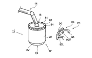
図1に示すように、この実施の形態に係る手術用立体観察装置10は、例えば術部等を観察するための鏡体12と、鏡体12を空間内の任意の位置に位置決め可能な支持アーム14とを備えている。支持アーム14は、例えば部屋の天井(図示せず)などに一端が支持され、他端が鏡体12に支持されている。すなわち、支持アーム14の他端部は、接続部16によって鏡体12に連結されている。
As shown in FIG. 1, the
鏡体12は、鏡体本体(ハウジング)22と、この鏡体本体22内に設けられた観察光学系24と、鏡体本体22の外周に配設された画像表示装置26とを備えている。この鏡体本体22は、天井側に向けられる一端部が閉塞され、術部側に向けられる他端部が開口された円筒状に形成されている。鏡体本体22の一端部には接続部16が配設され、支持アーム14に連結されている。
The
次に、手術用立体観察装置10の観察光学系24の構成について説明する。
Next, the configuration of the observation
図2に示すように、鏡体本体22には、対物レンズ(対物光学系)32と、第1ないし第5の鏡体内光学系34a−34eとが観察光学系24として配設されている。対物レンズ32は、鏡体本体22の他端部に配設され、鏡体本体22の内部を閉塞している。第1ないし第5の鏡体内光学系34a−34eは、対物レンズ32と鏡体本体22の一端部との間に配設されている。
As shown in FIG. 2, the
第1の鏡体内光学系34aは、第1のズーム光学系36aと、第1の結像レンズ38aと、第1の撮像素子40aとを対物レンズ32と鏡体本体22の一端部との間で対物レンズ32側から鏡体本体22の一端部側に向かって順次備えている。これら第1のズーム光学系36a、第1の結像レンズ38aおよび第1の撮像素子40aは、共通の第1の光軸Oaを光軸中心として配設されている。このため、対物レンズ32から鏡体本体22内に入射された光束は、第1のズーム光学系36aによって拡大され、第1の結像レンズ38aによって第1の撮像素子40aの撮像面に結像される。
The first lens body
第2の鏡体内光学系34bは、第2のズーム光学系36bと、第2の結像レンズ38bと、第2の撮像素子40bとを第1の鏡体内光学系34aに並設された状態で備えている。第3の鏡体内光学系34cは、第3のズーム光学系36cと、第3の結像レンズ38cと、第3の撮像素子40cとを第1および第2の鏡体内光学系34a,34bにそれぞれ並設された状態で備えている。
The second in-camera
第4の鏡体内光学系34dは、第4のズーム光学系36dと、第4の結像レンズ38dと、第4の撮像素子40dとを第1ないし第3の鏡体内光学系34a−34cにそれぞれ並設された状態で備えている。第5の鏡体内光学系34eは、第5のズーム光学系36eと、第5の結像レンズ38eと、第5の撮像素子40eとを第1ないし第4の鏡体内光学系34a−34dにそれぞれ並設された状態で備えている。
The fourth lens
第2の鏡体内光学系34bは共通の第2の光軸Obを光軸中心として配設され、第3の鏡体内光学系34cは共通の第3の光軸Ocを光軸中心として配設され、第4の鏡体内光学系34dは共通の第4の光軸Odを光軸中心として配設され、第5の鏡体内光学系34eは共通の第5の光軸Oeを光軸中心として配設されている。すなわち、鏡体12は、第1ないし第5の光軸Oa−Oeを光軸中心とする5本の光束を撮像可能に第1ないし第5の鏡体内光学系34a−34eを備えている。
The second lens
図3に示すように、第1ないし第5の光軸Oa−Oeは、対物レンズ32の中心軸Oからそれぞれ等距離離間した位置に配置されている。第1ないし第5の光軸Oa−Oeは、互いに隣接する光軸中心と等距離離間した位置に配置されている。例えば第1の光軸Oaは、第2の光軸Obと第5の光軸Oeと等距離離間している。第2の光軸Obは、第1の光軸Oaと第3の光軸Ocと等距離離間している。第3の光軸Ocは、第2の光軸Obと第4の光軸Odと等距離離間している。第4の光軸Odは、第3の光軸Ocと第5の光軸Oeと等距離離間している。第5の光軸Oeは、第4の光軸Odと第1の光軸Oaと等距離離間している。このように、第1ないし第5の光軸Oa−Oeは、対物レンズ32の中心軸Oを共通の中心とし、この中心軸Oに対して直交する面内で、中心軸Oから任意の距離の正五角形の頂点の位置に配置されている。
As shown in FIG. 3, the first to fifth optical axes Oa-Oe are arranged at positions spaced apart from the central axis O of the
次に、手術用立体観察装置10の画像表示装置26の構成について説明する。
Next, the configuration of the
図1および図4(A)に示すように、画像表示装置26は、第1および第2の回動部44a,44bと、第1および第2のモニタ支持部46a,46bと、第1および第2の立体モニタ48a,48bとを備えている。
As shown in FIGS. 1 and 4A, the
第1および第2の回動部44a,44bは、リング状に形成され、鏡体本体22の周囲に沿って回転可能に並設されている。これら第1および第2の回動部44a,44bの内周面には、それぞれ後述するピニオンギヤ54a,54bに対してラックとしての機能を有する第1および第2のギヤ50a,50bが形成されている。
The first and second rotating
第1のモニタ支持部46aの一端は第1の回動部44aに固定され、他端は第1のモニタ48aに固定されている。第2のモニタ支持部46bの一端は第2の回動部44bに固定され、他端は第2の立体モニタ48bに固定されている。なお、第1および第2の立体モニタ48a,48bは、それぞれレンチキュラー方式などの立体画像表示装置である。
One end of the first
図4(A)および図4(B)に示すように、第1の回動部44aの内周面に形成された第1のギヤ50aには、第1のピニオンギヤ54aが噛み合わせられている。この第1のピニオンギヤ54aは、第1のエンコーダ(移動量検出器)56のシャフト56aに固定されている。ここで、この第1のエンコーダ56は鏡体本体22と一体的に固定されている。この第1のエンコーダ56は、シャフト56aの回転量を検出し、鏡体本体22に対する第1の立体モニタ48aの相対位置を検出する検出手段としての機能を備えている。
As shown in FIGS. 4A and 4B, the
第2の回動部44bも第1の回動部44aと同様に形成されているので、第2の回動部44bの構成の説明は省略する。
Since the second
次に、この実施の形態に係る手術用立体観察装置10の第1ないし第5の鏡体内光学系34a−34eを用いて得られる画像を画像表示装置26を用いて表示するための電気的接続状態について説明する。
Next, an electrical connection for displaying an image obtained by using the first to fifth intra-camera
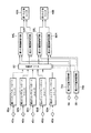
図5に示すように、第1ないし第5の撮像素子40a−40eは、対応する第1ないし第5のカメラコントロールユニット60a−60eに電気的に接続されている。第1ないし第5の撮像素子40a−40eによって撮像された信号は、対応する第1ないし第5のカメラコントロールユニット60a−60eに伝達され、それぞれ映像信号化される。
As shown in FIG. 5, the 1st thru | or 5th image pick-up
第1ないし第5のカメラコントロールユニット60a−60eは画像選択手段としての画像セレクタ62にそれぞれ電気的に接続されている。この画像セレクタ62は4つの映像出力端子(図示せず)を備えている。各映像出力端子は表示画像制御手段としての第1ないし第4の画像制御回路64L,64R,66L,66Rに電気的に接続されている。第1の画像制御回路64Lと第2の画像制御回路64Rとによって、1つの立体画像を作成し、第3の画像制御回路66Lと第4の画像制御回路66Rとによって、1つの立体画像を作成する。
The first to fifth
第1および第2の画像制御回路64L,64Rは、第1の立体モニタ48aに電気的に接続されている。このため、第1の立体モニタ48aは、第1および第2の画像制御回路64L,64Rそれぞれの画像、または、第1および第2の画像制御回路64L,64Rによって作成された立体画像を選択的に表示可能である。
The first and second
第3および第4の画像制御回路66L,66Rは、第2の立体モニタ48bに電気的に接続されている。このため、第2の立体モニタ48bは、第3および第4の画像制御回路66L,66Rそれぞれの画像、または、第3および第4の画像制御回路66L,66Rによって作成された立体画像を選択的に表示可能である。
The third and fourth
第1のエンコーダ56は、第1の回転制御回路70aに電気的に接続されている。第1の回転制御回路70aは、画像セレクタ62と、第1および第2の画像制御回路64L,64Rとに電気的に接続されている。
The
同様に第2のエンコーダ58は第2の回転制御回路70bに電気的に接続されている。第2の回転制御回路70bは、画像セレクタ62と、第3および第4の画像制御回路66L,66Rとに電気的に接続されている。
Similarly, the
次に、この実施の形態に係る手術用立体観察装置10の作用について説明する。
Next, the operation of the surgical
図示しない術者によって支持アーム14に支持された鏡体12を術部を観察する任意の位置に移動する。そうすると、鏡体12は所定の範囲内の所望の位置に配置される。
The
例えば術部から対物レンズ32によって鏡体本体22の内部に入射された光は、第1の鏡体内光学系34aでは、第1の光軸Oaを中心として第1のズーム光学系36aによって任意の倍率に拡大される。第1のズーム光学系36aによって拡大された光は、第1の結像レンズ38aで第1の撮像素子40a上に結像される。第1の撮像素子40aは、第1の撮像素子40a上で結像された像を撮像する。第1の撮像素子40aで撮像された画像は、第1の撮像素子40aから出力され、第1のカメラコントロールユニット60aに入力されて映像信号化される。
For example, the light incident on the inside of the
第2ないし第5の鏡体内光学系34b−34eでも、第2ないし第5の光軸Ob−Oeを中心とした光学像がそれぞれ第2ないし第5の撮像素子40b−40e上に結像される。第2ないし第5の撮像素子40b−40eは、第2ないし第5の撮像素子40b−40e上で結像された像をそれぞれ撮像する。第2ないし第5の撮像素子40b−40eで撮像された画像は、第2ないし第5の撮像素子40b−40eから出力され、第2ないし第5のカメラコントロールユニット60b−60eに入力されて映像信号化される。
Also in the second to fifth in-camera
第1ないし第5のカメラコントロールユニット60a−60eによって映像信号化された信号は第1ないし第5のカメラコントロールユニット60a−60eからそれぞれ出力され、画像セレクタ62に全て入力される。
The signals converted into video signals by the first to fifth
画像セレクタ62は、第1ないし第5のカメラコントロールユニット60a−60eによる映像信号を第1および第2の回転制御回路70a,70bから入力される信号に基づいて選択する。画像セレクタ62は、選択した映像信号を出力し、第1ないし第5のカメラコントロールユニット60a−60eの数(5つ)よりも少数の第1ないし第4の画像制御回路64L,64R,66L,66Rに入力される。すなわち、第1ないし第5のカメラコントロールユニット60a−60eから出力された映像信号の少なくとも1つは、画像セレクタ62で遮断される。
The
第1および第2の画像制御回路64L,64Rは、画像セレクタ62からの出力により入力された映像信号に基づいて映像を作成してその信号を出力する。第1および第2の画像制御装置64L,64Rから出力された信号は、それぞれ第1の立体モニタ48aに入力されてその映像が合成されて第1の立体モニタ48aに表示される。このため、第1の立体モニタ48aには、立体画像が表示される。
The first and second
なお、第1の立体モニタ48aは、第1および第2の画像制御回路64L,64Rによって作成された画像をそれぞれ選択的に、または同時に表示可能である。
Note that the first
同様に、第3および第4の画像制御回路66L,66Rは、画像セレクタ62からの出力により入力された映像信号に基づいて映像を作成してその信号を出力する。第3および第4の画像制御装置66L,66Rから出力された信号は、それぞれ第2の立体モニタ48bに入力されてその映像が合成されて第2の立体モニタ48bに表示される。このため、第2の立体モニタ48bには、立体画像が表示される。
Similarly, the third and fourth
なお、第2の立体モニタ48bは、第3および第4の画像制御回路66L,66Rによって作成された画像をそれぞれ選択的に、または同時に表示可能である。
The second
上述したように鏡体12を配置し、例えば術部を第1および第2の立体モニタ48a,48bで表示可能な状態で、術者の位置により、例えば第1の立体モニタ48aを術者の目の前に動かしたい場合がある。この場合、手術スタイルに応じて第1の立体モニタ48aを鏡体本体22の周りに回転させ、鏡体本体22に対する第1の立体モニタ48aの任意の位置を決める。具体的には、第1の立体モニタ48aの位置は、第1の回動部44aの鏡体本体22周りの回転によって移動する。
As described above, the
第1の回動部44aが鏡体本体22の周りに回転すると、第1の回動部44aの内周面の第1のギヤ50aが鏡体本体22の中心軸周りに移動する。第1のギヤ50aの移動は、第1のギヤ50aに噛み合わせられ、鏡体本体22に固定された第1のエンコーダ56のシャフト56aに固定されたピニオンギヤ54aの回転力に変換される。
When the first rotating
このため、このピニオンギヤ54aに回転により、第1のエンコーダ56のシャフト56aを回転させる。そうすると、第1のエンコーダ56によって第1の立体モニタ48aの鏡体本体22周りの回転量が検出される。この検出信号は、第1のエンコーダ56から出力され、第1の回転制御回路70aに入力される。第1の回転制御回路70aは、第1のエンコーダ56からの検出信号に基づいて第1の立体モニタ48aの位置を算出する。すなわち、第1のエンコーダ56による検出信号により、例えば対物レンズ32の中心軸Oに対して第1の光軸Oaからどれだけ回転した位置にあるかが第1の回転制御回路70aによって算出される。したがって、鏡体本体22に対する第1の立体モニタ48aの位置が算出される。
Therefore, the
第1の回転制御回路70aの算出信号は、第1の回転制御回路70aから出力され、画像セレクタ62と、第1および第2の画像制御回路64L,64Rとにそれぞれ入力される。このため、画像セレクタ62は、第1の立体モニタ48aの位置に基づいて第1ないし第5のカメラコントロールユニット60a−60eの映像信号のうちの2つを第1の立体モニタ48aに表示するために第1および第2の画像制御回路64L,64Rに出力する。第1および第2の画像制御回路は、第1の立体モニタ48aの位置に基づいて最適な画像が表示されるように画像セレクタ62から出力された映像信号を回転させる。
The calculation signal of the first
このため、第1および第2の画像制御回路64L,64Rによって映像が作成される。第1および第2の画像制御回路64L,64Rによって作成された映像は、第1の立体モニタ48aに出力され、第1の立体モニタ48aで例えば立体表示される。
Therefore, an image is created by the first and second
ここで、第1の立体モニタ48aを鏡体本体22の周りに回転させ、図6中に斜線で示す領域αに第1の立体モニタ48aを配置した場合について説明する。この領域αは対物レンズ32の中心軸Oから第1および第2の光軸Oa,Obに至る線分の延長線上で、鏡体本体22の周りに区切られる領域である。
Here, a case will be described in which the first
第1の回転制御回路70aの算出信号に基づいて、画像セレクタ62から第1および第2の画像制御回路64L,64Rに入力される信号が選択される。この場合、第1の画像制御回路64Lに入力される信号は第1の撮像素子40aによって撮像された信号が入力される。第2の画像制御回路64Rに入力される信号は第2の撮像素子40bによって撮像された信号が入力される。
Based on the calculation signal of the first
図7に示すように、第1の画像制御回路64Lは、第1の撮像素子40aにより撮像された画像から、第1の立体モニタ48aに表示する左側画像72Lの一部を切り出し、第1の立体モニタ48aの位置に基づいて切り出した左側画像74Lを回転させる。第2の画像制御回路64Rは、第2の撮像素子40bにより撮像された画像から、第1の立体モニタ48aに表示する右側画像72Rの一部を切り出し、第1の立体モニタ48aの位置に基づいて切り出した右側画像74Rを回転させる。第1の立体モニタ48aでは、第1および第2の画像制御回路64L,64Rによって切り出され、かつ、回転させた左側画像74Lおよび右側画像74Rを立体表示するために重ね合わせる。したがって、第1の立体モニタ48aには、第1および第2の鏡体内光学系34a,34bを用いて観察される画像74が立体表示される。
As shown in FIG. 7, the first
なお、第2の立体モニタ48bにおける画像も第1の立体モニタ48aにおける画像と同様にして作成されて表示される。第1の立体モニタ48aと第2の立体モニタ48bとが異なる位置に配置されている場合、互いに異なる画像が表示される。
The image on the second
以上説明したように、この実施の形態によれば、以下のことが言える。 As described above, according to this embodiment, the following can be said.
第1および第2の立体モニタ48a,48bを鏡体本体22の周りに回転可能に保持し、かつ、その第1および第2の立体モニタ48a,48bの鏡体本体22に対する相対位置を容易に検出可能である。そして、その相対位置に基づいて、第1および第2の立体モニタ48a,48bに表示される画像を選択し、また、その画像の向きを容易に設定することができる。
The first and second
ここでは、円筒状の鏡体本体22の中心軸と同一の中心軸を有する正五角形の頂点の位置にそれぞれ観察光学系24の第1ないし第5の光軸Oa−Oeを配置した。このため、隣接する光軸間距離と、中心軸Oに対する第1ないし第5の光軸Oa−Oeの距離とをそれぞれ一定に保つことができる。この状態で、第1の立体モニタ48aを鏡体本体22に対して回転させて術者が観察するのに最適な位置に配置した場合に、鏡体本体22に入射される立体画像を術者から術部を観察する方向と同一方向に表示させることができる。一方、第2の立体モニタ48bを鏡体本体22に対して回転させて助手が観察するのに最適な位置に配置した場合に、鏡体本体22に入射される立体画像を助手から術部を観察する方向と同一方向に表示させることができる。したがって、第1および第2の立体モニタ48a,48bを用いて術部を観察する場合に術者や助手がそれぞれ立体画像の向きを考慮することなく、観察することができる。
Here, the first to fifth optical axes Oa-Oe of the observation
したがって、鏡体12の周りに自在にモニタ48a,48bを配置することができるので、術者が術部に対して自由な位置・姿勢で、術部の拡大観察を行なうことができる。さらに、その観察画像が観察姿勢に対応した像の向きで、かつ、どの向きからも変わらぬ立体感で観察することができる。そうすると、術者の疲労軽減に効果があるとともに、手術の進行がスムーズになり、手術時間の短縮に効果がある。
Therefore, since the
次に、第2の実施の形態について図8ないし図12を用いて説明する。この実施の形態は第1の実施の形態の変形例であって、第1の実施の形態で説明した部材と同一の部材には同一の符号を付し、詳しい説明を省略する。 Next, a second embodiment will be described with reference to FIGS. This embodiment is a modification of the first embodiment. The same members as those described in the first embodiment are denoted by the same reference numerals, and detailed description thereof is omitted.
図8に示すように、この実施の形態に係る手術用立体観察装置10は、第1の実施の形態で説明した手術用立体観察装置10と同様に、鏡体12と、支持アーム14とを備えている。すなわち、支持アーム14の他端部は、接続部16によって鏡体12に連結されている。鏡体12は、鏡体本体(ハウジング)22と、この鏡体本体22内に設けられた観察光学系24と、鏡体本体22の外周に配設された画像表示装置26とを備えている。
As shown in FIG. 8, the surgical
次に、手術用立体観察装置10の観察光学系24の構成について説明する。この実施の形態に係る観察光学系24では、第1の実施の形態で説明した観察光学系24とは異なり、第1ないし第3の鏡体内光学系34a−34cのみを備えている。
Next, the configuration of the observation
図9に示すように、鏡体本体22には、対物レンズ32と、第1ないし第3の鏡体内光学系34a−34cとが観察光学系24として配設されている。すなわち、鏡体12は、第1ないし第3の光軸Oa−Ocを光軸中心とする3本の光束を撮像可能に第1ないし第3の鏡体内光学系34a−34cを備えている。
As shown in FIG. 9, the
図10に示すように、第1ないし第3の鏡体内光学系34a−34cの第1ないし第3の光軸Oa−Ocは、対物レンズ32の中心軸Oからそれぞれ等距離離間した位置に配置されている。第1ないし第3の光軸Oa−Ocは、互いに隣り合わせになる光軸と等距離離間した位置に配置されている。例えば第1の光軸Oaは、第2の光軸Obと第3の光軸Ocと等距離離間している。第2の光軸Obは、第1の光軸Oaと第3の光軸Ocと等距離離間している。このため、第1ないし第3の光軸Oa−Ocは、対物レンズ32の中心軸Oを共通の中心とした正三角形の頂点の位置に配置されている。
As shown in FIG. 10, the first to third optical axes Oa-Oc of the first to third intra-camera
鏡体本体22の内部で、第1ないし第3の光軸Oa−Ocを頂点とする正三角形の中心の位置、すなわち対物レンズ32の中心軸O上には、照明光学系76(図11参照)が配設されている。図11に示すように、照明光学系76は、図示しない照明電源に接続されて電力が供給されると発光する照明ランプ78と、この照明ランプ78の発光光を集光する集光レンズ80とを備えている。照明ランプ78は、鏡体本体22の閉塞された一端部側に配設されている。すなわち、照明ランプ78と対物レンズ32との間に集光レンズ80が配設されている。このため、照明ランプ78の発光光は、集光レンズ80を通して術部を照明可能である。
Inside the
次に、手術用立体観察装置10の画像表示装置26の構成について説明する。この実施の形態に係る画像表示装置26では、第1の実施の形態で説明した画像表示装置26とは異なり、第1および第2の回動部44a,44bが除去されている。
Next, the configuration of the
図8および図10に示すように、画像表示装置26は、第1ないし第3のモニタ支持部46a−46cと、第1ないし第3の立体モニタ48a−48cとを備えている。図10に示すように、第1ないし第3のモニタ支持部46a−46cの一端は、それぞれ鏡体本体22の外周に固定されている。第1のモニタ支持部46aの他端には、第1の立体モニタ48aが固定されている。第2のモニタ支持部46bの他端には、第2の立体モニタ48bが固定されている。第3のモニタ支持部46cの他端には、第3の立体モニタ48cが固定されている。
As shown in FIGS. 8 and 10, the
第1の立体モニタ48aの表示面は、第1の光軸Oaと第2の光軸Obとを結ぶ線分に対して平行に配置されている。同様に、第2の立体モニタ48bの表示面は、第2の光軸Obと第3の光軸Ocとを結ぶ線分に対して平行に配置されている。第3の立体モニタ48cの表示面は、第3の光軸Ocと第1の光軸Oaを結ぶ線分に対して平行に配置されている。
The display surface of the first
次に、この実施の形態に係る手術用立体観察装置10の第1ないし第3の鏡体内光学系34a−34cを用いて得られる画像を画像表示装置26を用いて表示するための電気的接続状態について説明する。
Next, an electrical connection for displaying an image obtained by using the first to third in-camera
図12に示すように、第1ないし第3の撮像素子40a−40cは、対応する第1ないし第3のカメラコントロールユニット60a−60cにそれぞれ電気的に接続されている。第1のカメラコントロールユニット60aは、第1の画像制御回路64Lおよび第6の画像制御回路68Rに電気的に接続されている。第2のカメラコントロールユニット60bは、第2の画像制御回路64Rおよび第3の画像制御回路66Lに電気的に接続されている。第3のカメラコントロールユニット60cは、第4の画像制御回路66Rおよび第5の画像制御回路68Lに電気的に接続されている。
As shown in FIG. 12, the first to
第1および第2の画像制御回路64L,64Rは、第1の立体モニタ48aに電気的に接続されている。第3および第4の画像制御回路66L,66Rは、第2の立体モニタ48bに電気的に接続されている。第5および第6の画像制御回路68L,68Rは、第3の立体モニタ48cに電気的に接続されている。
The first and second
第1の実施の形態で図5を用いて説明したブロック図の構成とは、画像セレクタ62および回転制御回路70a,70bの有無が主な相違点である。この実施の形態に係る手術用立体観察装置10では、画像セレクタ62および回転制御回路70a,70bが除去されている。
The main difference from the configuration of the block diagram described with reference to FIG. 5 in the first embodiment is the presence or absence of the
次に、この実施の形態に係る手術用立体観察装置10の作用について説明する。
Next, the operation of the surgical
照明光学系76の照明ランプ78の発光光は集光レンズ80および対物レンズ32によって適当に集光されて術部に照射される。このため、術部は、集光中心から適当な範囲内が照明される。
The light emitted from the
術部からの光は、対物レンズ32、第1ないし第3のズーム光学系36a−36c、および第1ないし第3の結像レンズ38a−38cを通して第1ないし第3の撮像素子40a−40cによってそれぞれ撮像される。
Light from the surgical site is transmitted through the
第1ないし第3の撮像素子40a−40cで撮像された画像は、第1ないし第3のカメラコントロールユニット60a−60cによって映像信号化される。第1のカメラコントロールユニット60aによる映像信号は、第1の画像制御回路64Lおよび第6の画像制御回路68Rに入力される。同様に、第2のカメラコントロールユニット60bの映像信号は第2および第3の画像制御回路64R,66Lに入力され、第3のカメラコントロールユニット60cの映像信号は第4および第5の画像制御回路66R,68Lに入力される。
Images captured by the first to
第1ないし第6の画像制御回路64L,64R,66L,66R,68L,68Rでは第1の実施の形態の図7に示す処理と同様の処理を行ない、第1ないし第3の立体モニタ48a−48cに観察像を表示する。この実施の形態では、前述した条件で配置される3本の光束を備えていることから、第1の立体モニタ48aに表示される切り出し画像との関係が一義的に決定される。
The first to sixth
前述した処理を行なった第1および第6の画像制御回路64L,68Rによる画像を切り出して、第1の立体モニタ48aに立体画像として表示される。同様に、第2および第3の画像制御回路64R,66Lの画像は第2の立体モニタ48bに立体画像として表示され、第4および第5の画像制御回路66R,68Lの画像は第3の立体モニタ48cで立体画像として表示される。もちろん、第1の立体モニタ48aは、第1の画像制御回路64Lによる画像のみを表示可能であり、第6の画像制御回路68Rによる画像のみを表示可能である。すなわち、第1の立体モニタ48aは、2つの画像を切り出して合わせた立体画像と、第1および第6の画像制御回路64L,68Rによる画像とを選択的に表示する。これは、第2および第3の立体モニタ48b,48cも同様である。
Images by the first and sixth
以上説明したように、この実施の形態によれば、以下のことが言える。 As described above, according to this embodiment, the following can be said.
立体観察可能な鏡体12周りの観察面ごとに立体モニタ、すなわち第1ないし第3の立体モニタ48a−48cが設けられているので、いちいち鏡体12に対する立体モニタ48a−48cの位置検出機構を設ける必要がなく、簡素な構成で所望の位置での立体観察を実現することができる。このため、術者が鏡体12の周りに観察角度を変えた場合でも、わざわざ立体モニタ48a−48cを鏡体12の周りに回転(移動)させる手間をなくすことができる。
Since a stereoscopic monitor, that is, the first to third
次に、第3の実施の形態について図13ないし図16を用いて説明する。この実施の形態は第1および第2の実施の形態の変形例であって、第1および第2の実施の形態で説明した部材と同一の部材には同一の符号を付し、詳しい説明を省略する。 Next, a third embodiment will be described with reference to FIGS. This embodiment is a modification of the first and second embodiments, and the same members as those described in the first and second embodiments are denoted by the same reference numerals, and detailed description will be given. Omitted.
図13に示すように、この実施の形態に係る手術用立体観察装置10は、第1の実施の形態で説明した手術用立体観察装置10と同様に、鏡体12と、支持アーム14とを備えている。すなわち、支持アーム14の他端部は、接続部16によって鏡体12に連結されている。
As shown in FIG. 13, the surgical
鏡体12は、鏡体本体(ハウジング)22と、この鏡体本体22内に設けられた観察光学系24と、鏡体本体22の一端部(閉塞部)の外縁部に並設された複数の受光素子84と、鏡体本体22に対して分離された画像表示装置26とを備えている。受光素子84は鏡体本体22の一端部の外縁部に等間隔に配置されている。これら受光素子84は、後述するFMD86の相対位置を検出する位置検出手段を構成する。
The
次に、手術用立体観察装置10の観察光学系24の構成について説明する。この実施の形態に係る観察光学系24では、第1および第2の実施の形態で説明した観察光学系24とは異なり、第1ないし第4の鏡体内光学系34a−34dを備えている。
Next, the configuration of the observation
図14に示すように、鏡体本体22には、対物レンズ32と、第1ないし第4の鏡体内光学系34a−34dとが観察光学系24として配設されている。すなわち、鏡体12は、第1ないし第4の光軸Oa−Odを光軸中心とする4本の光束を撮像可能に第1ないし第4の鏡体内光学系34a−34dを備えている。
As shown in FIG. 14, the
図15に示すように、第1ないし第3の鏡体内光学系34a−34cの第1ないし第3の光軸Oa−Ocは、第2の実施の形態で説明した第1ないし第3の鏡体内光学系34a−34cの第1ないし第3の光軸Oa−Ocと同様に配置されている。このため、第1ないし第3の光軸Oa−Ocは、対物レンズ32の中心軸Oを共通の中心とした正三角形の頂点の位置に配置されている。
As shown in FIG. 15, the first to third optical axes Oa-Oc of the first to third
第4の光軸Odは、第1ないし第3の光軸Oa−Ocによって形成される正三角形の外側に備えている。第4の光軸Odは、第1および第3の光軸Oa,Ocを結ぶ線分に対して対物レンズ32の中心に対して直交する方向に配置され、かつ、第1および第3の光軸Oa,Ocを結ぶ線分の長さと対物レンズ32の中心軸Oからの距離とが等しい位置に配置されている。すなわち、第1の光軸Oaと対物レンズ32の中心軸Oとの間、第1の光軸Oaと第4の光軸Odとの間、第2の光軸Obと対物レンズ32の中心軸Oとの間、第2の光軸Obと第4の光軸Odとの間のそれぞれの距離は等しい。
The fourth optical axis Od is provided outside the equilateral triangle formed by the first to third optical axes Oa-Oc. The fourth optical axis Od is arranged in a direction perpendicular to the center of the
次に、手術用立体観察装置10の画像表示装置26の構成について説明する。
Next, the configuration of the
図13に示すように、画像表示装置26は、術者の顔に装着して、物体の観察像を表示するフェイスマウントディスプレー(以下、FMDという)86を備えている。このFMD86は、FMD本体(FMDハウジング)88と、赤外ダイオード(IR−RED)90と、表示素子92L,92Rとを備えている。FMD本体88は、例えば眼鏡のように術者の顔面に装着される。FMD本体88は、例えばブリッジを有するフロントフレームと、術者の耳などにかけるための1対の蔓(つる)とを備えている。赤外ダイオード90は、ブリッジなどの前面に設けられ、受光素子84に向けて赤外光を発光する。表示素子92L,92Rは、FMD本体88のフロントフレームに装着され、術者の左眼および右眼にそれぞれ対応した位置に配置されている。
As shown in FIG. 13, the
次に、この実施の形態に係る手術用立体観察装置10の第1ないし第4の鏡体内光学系34a−34dを用いて得られる画像を画像表示装置26を用いて表示するための電気的接続状態について説明する。
Next, an electrical connection for displaying an image obtained using the first to fourth intra-camera
図16に示すように、第1ないし第4の撮像素子40a−40dは、対応する第1ないし第4のカメラコントロールユニット60a−60dにそれぞれ電気的に接続されている。第1ないし第4のカメラコントロールユニット60a−60dは、それぞれ画像セレクタ62に電気的に接続されている。
As shown in FIG. 16, the first to
この画像セレクタ62は2つの映像出力端子(図示せず)を備えている。各映像出力端子は表示画像制御手段としての第1および第2の画像制御回路64L,64Rに電気的に接続されている。第1の画像制御回路64Lは、FMD86の左眼用表示素子92Lに電気的に接続されている。第2の画像制御回路64Rは、FMD86の右眼用表示素子92Rに電気的に接続されている。
The
各受光素子84は、位置検出回路94に電気的に接続されている。この位置検出回路94には、図示しないメモリなどの記録手段によって受光素子84の鏡体12に対する位置と、第1ないし第4の光軸Oa,Odの位置との関係が予め記録されている。この位置検出回路94は、画像セレクタ62、第1および第2の画像制御回路64L,64Rに電気的に接続されている。
Each
次に、この実施の形態に係る手術用立体観察装置10の作用について説明する。
Next, the operation of the surgical
対物レンズ32を通して鏡体本体22内に入射された光束は第1の実施の形態に係る手術用立体観察装置10と同様に各々の撮像素子40a−40dで撮像される。各撮像素子40a−40dに電気的に接続されたカメラコントロールユニット60a−60dで映像信号化されて映像信号化される。
The light beam that has entered the
第1ないし第4のカメラコントロールユニット60a−60dによって映像信号化された信号は、第1ないし第4のカメラコントロールユニット60a−60dからそれぞれ出力され、画像セレクタ62に全て入力される。
The signals converted into video signals by the first to fourth
ここで、FMD86の赤外ダイオード90から発せられた赤外光は、FMD86を装着した術者に近接する位置の受光素子84によって受光される。受光素子84によって赤外光が受光されると、その受光素子84は、位置検出回路94にその信号を送信する。位置検出回路94は、複数の受光素子84のうち赤外光を受光した受光素子84の位置に基づいて術者の位置(赤外ダイオード90による赤外光の発光位置)を特定する。すなわち、鏡体本体22に対する各受光素子84の位置と、各光軸中心Oa−Odの位置関係とから赤外ダイオード90による発光光に対する周方向の位置が検出されて特定される。
Here, the infrared light emitted from the
画像セレクタ62は、第1ないし第4のカメラコントロールユニット60a−60dによる映像信号を位置検出回路94から入力される信号に基づいて選択する。画像セレクタ62は、選択した映像信号を出力し、第1ないし第4のカメラコントロールユニット60a−60dの数(4つ)よりも少数の第1および第2の画像制御回路64L,64Rに入力される。すなわち、第1ないし第4のカメラコントロールユニット60a−60dから出力された映像信号の少なくとも2つは、画像セレクタ62で遮断される。
The
FMD86の位置が図15に示す矢印(観察方向)D1の位置にあり、その位置が前記位置検出回路94によって検出された場合について説明する。
The case where the position of the
FMD86の赤外ダイオード90からの赤外光の向きが観察方向D1のとき、位置検出回路94からの信号によって画像セレクタ62は第3の撮像素子40cによって得られる映像信号を画像制御回路64Lに出力し、かつ第1の撮像素子40aによって得られる映像信号を画像制御回路64Rに出力する。
When the direction of the infrared light from the
画像制御回路64L,64Rでは位置検出回路94の信号に基づいて所定の画像の向きで映像信号を切り出す処理を行ない(図7参照)、FMD86の各々の表示素子92L,92Rに表示する。ここでは観察方向D1であり、図15に示す向きに撮像素子が取り付けられているので画像の向きは変えずに、表示素子92L,92Rに表示可能な大きさで切り出すのみの制御となる。
The
FMD86が観察方向D6にあるとき、位置検出回路94からの信号によって画像セレクタ62は第2の撮像素子40bによって得られる映像信号を画像制御回路64Lに出力し、かつ第3の撮像素子40cによって得られる映像信号を画像制御回路64Rに出力する。画像制御回路64L,64Rは線分Ob−Ocが画像の底面となるように画像の向きを変えて、それぞれ表示素子92L,92Rに映像信号を出力する。
When the
以下同様に、観察方向が矢印D4または矢印D8の場合には、第1および第2の撮像素子40a,40bによって得られる映像信号を、観察方向が矢印D3または矢印D7の場合には、第2および第4の撮像素子40b,40dによって得られる映像信号を選択して、切り出して対応する左右の表示素子92L,92Rに表示する。
Similarly, when the observation direction is the arrow D4 or the arrow D8, the video signals obtained by the first and
以上説明したように、この実施の形態によれば以下のことが言える。 As described above, according to this embodiment, the following can be said.
術者(FMD86)が鏡体12の周りに移動しても自動的に術者の向きにあった画像が選択されるとともに、4つの撮像素子40a−40dで例えば8方向から、立体感がほとんど変わらない観察像を得ることができる。
Even if the surgeon (FMD 86) moves around the
なお、この実施の形態では、観察像を表示する表示手段としてFMD86を用いたが、第1の実施の形態で説明したように、鏡体本体22の周方向に沿って移動可能な立体表示装置26を用いても良い。
In this embodiment, the
これまで、いくつかの実施の形態について図面を参照しながら具体的に説明したが、この発明は、上述した実施の形態に限定されるものではなく、その要旨を逸脱しない範囲で行なわれるすべての実施を含む。 Although several embodiments have been specifically described so far with reference to the drawings, the present invention is not limited to the above-described embodiments, and all the embodiments performed without departing from the scope of the invention are described. Including implementation.
上記説明によれば、下記の事項の発明が得られる。また、各項の組み合わせも可能である。 According to the above description, the following matters can be obtained. Combinations of the terms are also possible.
[付記]
(付記項1)
少なくとも3つ以上の観察光学系及び前記観察光学系による光束を各々撮像するための複数の撮像手段とを有する鏡体部と、
一対の前記光束の撮像手段による画像を表示する一つないし複数の立体画像表示手段と、
前記鏡体部及び立体画像表示手段の相対位置を検出する位置検出手段と、
を有する手術用立体画像観察装置において
前記位置検出手段の検出結果に基づいて一対の前記撮像手段による画像を選択する画像選択手段と、
前記画像選択手段に基づき表示形態を制御する表示画像制御手段と、
を有することを特徴とする手術用立体画像観察装置。
[Appendix]
(Additional item 1)
A mirror unit having at least three or more observation optical systems and a plurality of imaging means for imaging the light beams by the observation optical systems;
One or a plurality of stereoscopic image display means for displaying an image by the pair of light flux imaging means;
Position detecting means for detecting a relative position of the mirror part and the stereoscopic image display means;
An image selecting means for selecting an image by the pair of imaging means based on a detection result of the position detecting means;
Display image control means for controlling the display form based on the image selection means;
A stereoscopic image observation apparatus for surgery characterized by comprising:
(付記項2)
前記光束は光束と平行な所定の軸中心に略等距離離間し、かつ互いに隣り合わせとなる各光束との距離が等しくなるよう配置されたことを特徴とする付記項1に記載の手術用立体画像観察装置。
(Appendix 2)
The three-dimensional image for surgery according to claim 1, wherein the luminous fluxes are arranged substantially equidistantly from each other at a center of a predetermined axis parallel to the luminous flux, and are arranged such that the distances between the luminous fluxes adjacent to each other are equal. Observation device.
(付記項3)
前記立体画像表示手段は一対の所定の撮像手段に対応する数だけ設けられるとともに、
前記撮像手段による撮像画像を各々の立体画像表示手段に対応した表示形態に制御する制御手段を有すること
を特徴とする手術用立体画像観察装置。
(Additional Item 3)
The stereoscopic image display means is provided in a number corresponding to a pair of predetermined imaging means,
A surgical stereoscopic image observation apparatus, comprising: a control unit that controls a captured image obtained by the imaging unit to a display form corresponding to each stereoscopic image display unit.
(付記項4)
4つの観察光学系による光束を各々撮像するための4つの撮像手段と、
前記撮像手段による所定の一対の画像を立体表示するための立体画像表示手段と、
を有する立体画像観察装置において、
前記4つの観察光学系のうち、3つは互いにその距離が等しくなる位置に配置されて光軸中心が略正三角形を構成するとともに、
残る一つの観察光学系が任意の頂点から略正三角形を2分する線分方向に、前記略正三角形の一辺と略等距離離間した位置に配置されること
を特徴とする手術用立体画像観察装置。
(Appendix 4)
Four image pickup means for picking up images of light beams by the four observation optical systems,
Stereoscopic image display means for stereoscopically displaying a predetermined pair of images by the imaging means;
In a stereoscopic image observation apparatus having
Of the four observation optical systems, three are arranged at positions where the distances are equal to each other, and the optical axis center forms a substantially equilateral triangle,
Surgical stereoscopic image observation characterized in that the remaining one observation optical system is arranged at a position approximately equidistant from one side of the substantially equilateral triangle in a line segment direction that bisects the equilateral triangle from an arbitrary vertex. apparatus.
(付記項5)
鏡体本体と、この鏡体本体内に設けられ、前記鏡体本体内に入射される光を撮像する撮像手段をそれぞれ有する少なくとも3つの観察光学系とを有する鏡体と、
前記撮像手段で撮像された像のうち、少なくとも1対の画像を選択する画像選択手段と、
前記画像選択手段により選択された画像の表示形態を制御する表示画像制御手段と、
前記表示画像制御手段により作成された画像を立体表示可能な立体画像表示機構と
を具備することを特徴とする立体画像観察装置。
(Appendix 5)
A mirror body having a mirror body, and at least three observation optical systems provided in the mirror body and each having imaging means for imaging light incident on the mirror body;
Image selection means for selecting at least one pair of images among the images picked up by the image pickup means;
Display image control means for controlling the display form of the image selected by the image selection means;
A stereoscopic image observation apparatus, comprising: a stereoscopic image display mechanism capable of stereoscopically displaying an image created by the display image control means.
(付記項6)
前記鏡体および前記立体画像表示装置の相対位置を検出する位置検出機構をさらに具備することを特徴とする付記項5に記載の立体画像観察装置。
(Appendix 6)
6. The stereoscopic image observation apparatus according to appendix 5, further comprising a position detection mechanism that detects a relative position between the mirror body and the stereoscopic image display apparatus.
(付記項7)
前記各観察光学系は、所定の軸中心に対して略等距離離間し、かつ、互いに隣接する観察光学系に対して等距離離間した光軸を有することを特徴とする付記項5もしくは付記項6に記載の立体画像観察装置。
(Appendix 7)
Each of the observation optical systems has an optical axis that is substantially equidistant from a predetermined axis center and that is equidistant from adjacent observation optical systems. The three-dimensional image observation apparatus according to 6.
(付記項8)
前記観察光学系は、前記鏡体本体に配設され、他の観察光学系と共同して使用される対物光学系と、前記撮像手段に前記対物光学系によって入射された光を結像する結像レンズとをそれぞれさらに備えていることを特徴とする付記項5ないし付記項7のいずれか1に記載の立体画像観察装置。
(Appendix 8)
The observation optical system is disposed in the body of the mirror and is used in combination with an objective optical system that is used in cooperation with another observation optical system, and images the light incident on the imaging means by the objective optical system. The stereoscopic image observation apparatus according to any one of supplementary items 5 to 7, further comprising an image lens.
(付記項9)
前記鏡体は、筒状の鏡体本体を備え、
前記観察光学系は、前記鏡体本体の一端部の開口部に設けられた対物光学系を備え
前記観察光学系の少なくとも一部は、前記対物光学系の中心軸と同一の中心軸を有する略正多角形の頂点の位置に配置されていることを特徴とする付記項5ないし付記項8のいずれか1に記載の立体画像観察装置。
(Appendix 9)
The mirror body includes a cylindrical mirror body,
The observation optical system includes an objective optical system provided in an opening at one end of the mirror body. At least a part of the observation optical system has a central axis that is the same as the central axis of the objective optical system. The three-dimensional image observation device according to any one of supplementary items 5 to 8, wherein the stereoscopic image observation device is disposed at a vertex of a regular polygon.
(付記項10)
鏡体本体と、
前記鏡体本体に設けられ、前記鏡体本体の内部に入射される光による像を撮像するための少なくとも4つの撮像手段を有する観察光学系と、
前記観察像画像の表示形態を制御する表示画像制御手段と、
前記撮像手段により撮像された画像のうち、選択された1対の画像を立体表示可能な立体画像表示手段と
を具備し、
前記観察光学系は、前記観察光学系の数よりも1つ少ない観察光学系の数の頂点を有する略正多角形の頂点にそれぞれ光軸を備え、残りの1つの観察光学系が前記略正多角形の互いに隣接する任意の頂点間を結ぶ線分に対して直交し、かつ、前記線分を二分する線分上で前記略正多角形の中心から前記頂点間を結ぶ線分を越えた位置に配置され、前記略正多角形の一辺と略等距離離間した位置に光軸を備えていることを特徴とする立体画像観察装置。
(Appendix 10)
The body of the mirror,
An observation optical system provided in the mirror body and having at least four imaging means for capturing an image of light incident on the interior of the mirror body;
Display image control means for controlling the display form of the observation image,
A stereoscopic image display means capable of stereoscopically displaying a pair of images selected from the images captured by the imaging means;
The observation optical system includes optical axes at the vertices of substantially regular polygons each having one vertex less than the number of the observation optical systems, and the remaining one observation optical system is the substantially regular optical system. It is orthogonal to a line segment connecting arbitrary adjacent vertices of the polygon, and exceeds a line segment connecting the vertices from the center of the substantially regular polygon on a line segment that bisects the line segment. A stereoscopic image observing apparatus comprising an optical axis at a position which is disposed at a position and is spaced approximately equidistant from one side of the substantially regular polygon.
(付記項11)
前記鏡体に対する前記立体画像表示機構の相対位置を検出する位置検出手段をさらに備えていることを特徴とする付記項10に記載の立体画像観察装置。
(Appendix 11)
The stereoscopic image observation apparatus according to
(付記項12)
前記鏡体は、前記観察光学系が配設された鏡体本体と、前記立体画像表示機構が前記鏡体本体の外周に対して移動可能に設けられた移動部とを備え、
前記位置検出手段は、前記鏡体本体対して固定され、前記鏡体本体に対する前記移動部の移動量を検出する移動量検出器を備えていることを特徴とする付記項11に記載の立体画像観察装置。
(Appendix 12)
The mirror body includes a mirror body in which the observation optical system is disposed, and a moving unit in which the stereoscopic image display mechanism is provided to be movable with respect to an outer periphery of the mirror body.
The three-dimensional image according to claim 11, wherein the position detection unit includes a movement amount detector that is fixed to the mirror body and detects a movement amount of the moving unit with respect to the mirror body. Observation device.
(付記項13)
前記立体画像表示機構は、左眼用および右眼用の画像が分離して表示される左眼用表示部および右眼用表示部を備えていることを特徴とする付記項12に記載の立体画像観察装置。
(Appendix 13)
The three-dimensional image display mechanism includes a left-eye display unit and a right-eye display unit on which a left-eye image and a right-eye image are displayed separately, and the three-dimensional image display mechanism according to
(付記項14)
前記立体画像表示機構は、左眼用および右眼用の画像がそれぞれ独立して表示される少なくとも1対の表示部と、所定の方向に向かって光を出射する光出力機構とを有するフェイスマウントディスプレーを備え、
前記鏡体は、前記観察光学系が配設された鏡体本体を備え、
前記位置検出手段は、前記鏡体本体に等間隔に並設され、前記光出力機構から出射された光を検出する複数の光検出センサを備えていることを特徴とする付記項11に記載の立体画像観察装置。
(Appendix 14)
The stereoscopic image display mechanism includes a face mount having at least one pair of display units for independently displaying images for the left eye and the right eye, and a light output mechanism for emitting light in a predetermined direction. With a display,
The mirror body includes a mirror body in which the observation optical system is disposed,
(付記項15)
前記被仮出力機構は、赤外線を出射する赤外線出射機構を備え、
前記光検出センサは、任意の閾値以上の前記赤外線を検出する赤外線受光センサを備えていることを特徴とする付記項14に記載の立体画像観察装置。
(Appendix 15)
The provisional output mechanism includes an infrared emission mechanism that emits infrared rays,
15. The three-dimensional image observation apparatus according to
(付記項16)
鏡体本体と、
前記鏡体本体に設けられ、前記鏡体本体の内部に入射される光による像を撮像するための少なくとも4つの撮像手段を有する観察光学系と、
前記観察光学系により得られた画像を選択する画像選択手段と、
前記画像選択手段により選択された画像の表示形態を制御する表示画像制御手段と、
前記撮像手段により撮像された画像のうち、選択された1対の画像を立体表示可能な立体画像表示手段と
を具備し、
前記観察光学系は、前記観察光学系の数よりも1つ少ない観察光学系の数が奇数の頂点を有する略正多角形の頂点にそれぞれ光軸を備え、残りの1つの観察光学系が前記略正多角形の互いに隣接する任意の頂点間を結ぶ線分に対して対向した頂点から前記線分を二分する線分上で前記対向した頂点から前記頂点間を結ぶ線分を越えた位置に配置され、前記対向した頂点と前記頂点間を結ぶ線分の一端の頂点との間と略等距離離間した位置に光軸を備えていることを特徴とする立体画像観察装置。
(Appendix 16)
The body of the mirror,
An observation optical system provided in the mirror body and having at least four imaging means for capturing an image of light incident on the interior of the mirror body;
Image selection means for selecting an image obtained by the observation optical system;
Display image control means for controlling the display form of the image selected by the image selection means;
A stereoscopic image display means capable of stereoscopically displaying a pair of images selected from the images captured by the imaging means;
The observation optical system includes optical axes at the vertices of substantially regular polygons each having an odd number of vertices, the number of observation optical systems being one less than the number of the observation optical systems, and the remaining one observation optical system is the On a line segment that bisects the line segment from the opposite vertex to a line segment that connects between any adjacent vertices of a substantially regular polygon at a position beyond the line segment that connects the vertex from the opposite vertex. A three-dimensional image observation apparatus comprising an optical axis at a position that is arranged and spaced approximately equidistant from a vertex of one end of a line segment that connects the vertex and the opposed vertex.
(付記項17)
前記鏡体に対する前記立体画像表示機構の相対位置を検出する位置検出手段をさらに備えていることを特徴とする付記項16に記載の立体画像観察装置。
(Appendix 17)
The stereoscopic image observation apparatus according to
(付記項18)
前記鏡体は、前記観察光学系が配設された鏡体本体と、前記立体画像表示機構が前記鏡体本体の外周に対して移動可能に設けられた移動部とを備え、
前記位置検出手段は、前記鏡体本体対して固定され、前記鏡体本体に対する前記移動部の移動量を検出する移動量検出器を備えていることを特徴とする付記項17に記載の立体画像観察装置。
(Appendix 18)
The mirror body includes a mirror body in which the observation optical system is disposed, and a moving unit in which the stereoscopic image display mechanism is provided to be movable with respect to an outer periphery of the mirror body.
The three-dimensional image according to claim 17, wherein the position detection unit includes a movement amount detector fixed to the mirror body and detecting a movement amount of the moving unit with respect to the mirror body. Observation device.
(付記項19)
前記立体画像表示機構は、左眼用および右眼用の画像が分離して表示される左眼用表示部および右眼用表示部を備えていることを特徴とする付記項18に記載の立体画像観察装置。
(Appendix 19)
The three-dimensional image display mechanism includes a left-eye display unit and a right-eye display unit on which a left-eye image and a right-eye image are displayed separately, and the three-dimensional image display mechanism according to Additional Item 18, Image observation device.
(付記項20)
前記立体画像表示機構は、左眼用および右眼用の画像がそれぞれ独立して表示される少なくとも1対の表示部と、所定の方向に向かって光を出射する光出力機構とを有するフェイスマウントディスプレーを備え、
前記鏡体は、前記観察光学系が配設された鏡体本体を備え、
前記位置検出手段は、前記鏡体本体に等間隔に並設され、前記光出力機構から出射された光を検出する複数の光検出センサを備えていることを特徴とする付記項17に記載の立体画像観察装置。
(Appendix 20)
The stereoscopic image display mechanism includes a face mount having at least one pair of display units for independently displaying images for the left eye and the right eye, and a light output mechanism for emitting light in a predetermined direction. With a display,
The mirror body includes a mirror body in which the observation optical system is disposed,
Item 18. The supplementary item 17, wherein the position detection means includes a plurality of light detection sensors that are arranged in parallel to the mirror body at equal intervals and detect light emitted from the light output mechanism. Stereoscopic image observation device.
(付記項21)
前記被仮出力機構は、赤外線を出射する赤外線出射機構を備え、
前記光検出センサは、任意の閾値以上の前記赤外線を検出する赤外線受光センサを備えていることを特徴とする付記項20に記載の立体画像観察装置。
(Appendix 21)
The provisional output mechanism includes an infrared emission mechanism that emits infrared rays,
The three-dimensional image observation apparatus according to Additional Item 20, wherein the light detection sensor includes an infrared light receiving sensor that detects the infrared light having an arbitrary threshold value or more.
(付記項22)
鏡体内に配置された少なくとも3つの観察光学系でそれぞれ異なる観察像を得る工程と、
前記観察像を映像信号化する工程と、
鏡体に対して相対的に移動可能なモニタの鏡体に対する位置を検出する工程と、
前記映像信号化した観察像を前記モニタの位置に基づいて選択する工程と、
選択した観察像を切り出す工程と、
前記観察像を重ね合わせて前記モニタに表示する工程と
を具備する立体画像観察方法。
(Appendix 22)
Obtaining different observation images with at least three observation optical systems arranged in the lens body;
Converting the observation image into a video signal;
Detecting a position of the monitor relative to the mirror that is movable relative to the mirror;
Selecting the imaged observation image based on the position of the monitor;
Cutting out the selected observation image;
A method of superimposing the observed images and displaying the images on the monitor.
(付記項23)
鏡体内に配置された少なくとも3つの観察光学系でそれぞれ異なる観察像を得る工程と、
前記観察像を映像信号化する工程と、
鏡体の外側で前記観察光学系の光軸に平行に配置されたモニタに合わせて観察像を切り出す工程と、
前記観察像を重ね合わせて前記モニタに表示する工程と
を具備する立体画像観察方法。
(Appendix 23)
Obtaining different observation images with at least three observation optical systems arranged in the lens body;
Converting the observation image into a video signal;
Cutting out an observation image according to a monitor arranged outside the mirror body in parallel with the optical axis of the observation optical system;
A method of superimposing the observed images and displaying the images on the monitor.
(付記項24)
鏡体内に配置された少なくとも3つの観察光学系でそれぞれ異なる観察像を得る工程と、
前記観察像を映像信号化する工程と、
鏡体に対して相対的に移動可能なモニタの鏡体に対する位置を検出する工程と、
前記映像信号化した観察像を前記モニタの位置に基づいて選択する工程と、
選択した観察像の画像を切り出す工程と、
前記観察像を前記モニタに表示する工程と
を具備する立体画像観察方法。
(Appendix 24)
Obtaining different observation images with at least three observation optical systems arranged in the lens body;
Converting the observation image into a video signal;
Detecting a position of the monitor relative to the mirror that is movable relative to the mirror;
Selecting the imaged observation image based on the position of the monitor;
Cutting out the image of the selected observation image;
And a step of displaying the observation image on the monitor.
(付記項25)
それぞれ異なる観察像を得る少なくとも3つの観察光学系を有し、前記観察光学系のうちの少なくとも一部の前記観察光学系の光軸中心が互いに対して略等距離離間した状態で配置された鏡体と、
前記鏡体の外側に設けられ、観察像を立体表示可能な立体画像表示機構と、
前記観察像の表示形態を制御し、前記立体画像表示機構に前記観察像を立体表示可能な表示画像制御手段と
を具備することを特徴とする立体画像観察装置。
(Appendix 25)
A mirror having at least three observation optical systems for obtaining different observation images, wherein the optical axis centers of at least some of the observation optical systems are substantially equidistant from each other. Body,
A stereoscopic image display mechanism provided outside the mirror body and capable of stereoscopically displaying an observation image;
A stereoscopic image observation apparatus comprising: a display image control unit that controls a display form of the observation image and capable of stereoscopically displaying the observation image on the stereoscopic image display mechanism.
(付記項26)
前記鏡体に対する前記立体画像表示機構の相対位置を検出する位置検出手段と、
前記観察光学系により得られた観察像を前記立体画像表示機構に表示するために前記位置検出手段による検出位置に基づいて最適に選択する画像選択手段と
をさらに具備することを特徴とする付記項25に記載の立体画像観察装置。
(Appendix 26)
Position detecting means for detecting a relative position of the stereoscopic image display mechanism with respect to the mirror body;
And an image selection unit that optimally selects an observation image obtained by the observation optical system based on a detection position by the position detection unit in order to display the observation image on the stereoscopic image display mechanism. The stereoscopic image observation apparatus according to 25.
(付記項27)
前記鏡体は、筒状の鏡体本体を備え、
前記観察光学系は、前記鏡体本体の一端部の開口部に設けられた共通の対物光学系を備え、
前記観察光学系の少なくとも一部は、前記対物光学系の中心軸に対して直交する面内で、前記中心軸を中心とする略正多角形の頂点の位置に光軸をそれぞれ備えていることを特徴とする付記項25もしくは付記項26に記載の立体画像観察装置。
(Appendix 27)
The mirror body includes a cylindrical mirror body,
The observation optical system includes a common objective optical system provided at an opening at one end of the mirror body,
At least a part of the observation optical system includes an optical axis at a vertex of a substantially regular polygon centered on the central axis in a plane orthogonal to the central axis of the objective optical system. The stereoscopic image observation apparatus according to Supplementary Note 25 or
このため、対物光学系の中心軸を中心として略等距離に観察光学系を配置することができる。そうすると、例えば鏡体の外周に複数の立体画像表示機構を配置したときに容易に観察することができる。 For this reason, the observation optical system can be arranged at substantially equal distances around the central axis of the objective optical system. Then, for example, when a plurality of stereoscopic image display mechanisms are arranged on the outer periphery of the mirror body, it can be easily observed.
(付記項28)
前記立体画像表示機構は、前記略正多角形の辺の数と同じ数の表示部を備え、
前記表示部の表示面は、前記略正多角形の隣接する頂点を結ぶ線分に対してそれぞれ平行に配設されていることを特徴とする付記項27に記載の立体画像観察装置。
(Appendix 28)
The stereoscopic image display mechanism includes the same number of display units as the number of sides of the substantially regular polygon,
28. The stereoscopic image observation apparatus according to appendix 27, wherein the display surface of the display unit is arranged in parallel to a line segment connecting adjacent vertices of the substantially regular polygon.
このため、略正多角形の頂点に配置された隣接する観察光学系を用いてその頂点同士を結ぶ線分に平行に設けられた表示部を有する立体画像表示機構を用いて観察像を立体観察可能である。このとき、表示部に向かって左側および右側が自動的に規定されるので、観察像を回転等させることなく、向きをそのまま認識することができる。 For this reason, the observation image is stereoscopically observed using a stereoscopic image display mechanism having a display unit provided in parallel with a line segment connecting the vertices using adjacent observation optical systems arranged at the vertices of a substantially regular polygon. Is possible. At this time, since the left side and the right side are automatically defined toward the display unit, the orientation can be recognized as it is without rotating the observation image.
(付記項29)
前記鏡体は、筒状の鏡体本体を備え、
前記観察光学系は、前記鏡体本体の一端部の開口部に設けられた共通の対物光学系を備え、
前記鏡体本体は、前記対物光学系の中心軸上に配置された照明光学系を備えていることを特徴とする付記項25ないし付記項28のいずれか1に記載の立体画像観察装置。
(Appendix 29)
The mirror body includes a cylindrical mirror body,
The observation optical system includes a common objective optical system provided at an opening at one end of the mirror body,
The stereoscopic image observation apparatus according to any one of appendices 25 to 28, wherein the mirror body includes an illumination optical system disposed on a central axis of the objective optical system.
このため、例えば術部等を鏡体の外側から照明する必要がなく、より確実な照明を得ることができる。 For this reason, for example, it is not necessary to illuminate the surgical site or the like from the outside of the mirror body, and more reliable illumination can be obtained.
(付記項30)
前記立体画像表示機構は、左眼用および右眼用の画像がそれぞれ独立して表示される少なくとも1対の表示部と、所定の方向に向かって光を出射する光出力機構とを有するフェイスマウントディスプレーを備え、
前記鏡体は、前記観察光学系が配設された鏡体本体を備え、
前記位置検出手段は、前記鏡体本体に略等間隔に並設され、前記信号出力機構から発する信号を検出する複数の信号検出センサを備えていることを特徴とする付記項25ないし付記項27のいずれか1に記載の立体画像観察装置。
(Appendix 30)
The stereoscopic image display mechanism includes a face mount having at least one pair of display units for independently displaying images for the left eye and the right eye, and a light output mechanism for emitting light in a predetermined direction. With a display,
The mirror body includes a mirror body in which the observation optical system is disposed,
Item 25 to Item 27, wherein the position detection means includes a plurality of signal detection sensors that are arranged in parallel at substantially equal intervals on the body of the mirror and detect signals emitted from the signal output mechanism. The stereoscopic image observation device according to any one of the above.
このため、鏡体本体に対してフェイスマウントディスプレーが移動する、すなわち、術者が移動するとともに、信号出力機構による信号を検出センサで検出可能であるので、向きが最適な立体観察像を常に得ることが可能である。 For this reason, the face mount display moves with respect to the body of the mirror, that is, the operator moves, and the signal output mechanism can detect the signal by the detection sensor, so that a stereoscopic observation image with the optimum orientation is always obtained. It is possible.
(付記項31)
前記鏡体は、前記鏡体本体の外側に設けられ、前記立体画像表示機構を前記鏡体本体の外周に対して移動可能な移動部をさらに備えていることを特徴とする付記項25ないし付記項27のいずれか1に記載の立体画像観察装置。
(Appendix 31)
The mirror body further includes a moving part that is provided outside the mirror body and is capable of moving the stereoscopic image display mechanism with respect to the outer periphery of the mirror body. Item 28. The stereoscopic image observation device according to any one of Item 27.
このため、立体画像表示機構を術者に対して最適な向きに向けることができる。 For this reason, the stereoscopic image display mechanism can be oriented in an optimum direction with respect to the operator.
(付記項32)
前記立体画像表示機構は、観察像を立体表示する立体モニタを備えていることを特徴とする付記項25ないし付記項29のいずれか1に記載の立体画像観察装置。
(Appendix 32)
30. The stereoscopic image observation apparatus according to any one of supplementary items 25 to 29, wherein the stereoscopic image display mechanism includes a stereoscopic monitor that stereoscopically displays an observation image.
このため、立体モニタを用いて観察像を立体観察可能である。 For this reason, the observation image can be stereoscopically observed using the stereoscopic monitor.
(付記項33)
鏡体本体と、
前記鏡体本体に設けられ、それぞれ異なる観察像を得る少なくとも4つの観察光学系と、
前記観察像の表示形態を制御する表示画像制御手段と、
前記撮像手段により撮像された画像のうち1対の画像を立体表示可能な立体画像表示手段と
を具備し、
前記観察光学系は、前記観察光学系の数よりも少なくとも1つ少ない観察光学系の数の頂点を有する略正多角形の頂点にそれぞれ光軸を備え、残りの観察光学系が前記略正多角形の互いに隣接する任意の頂点間を結ぶ線分に対して直交し、かつ、前記線分を二分する線分上で前記略正多角形の中心から前記頂点間を結ぶ線分を越えた位置に配置され、前記略正多角形の一辺と略等距離離間した位置に光軸を備えていることを特徴とする立体画像観察装置。
(Appendix 33)
The body of the mirror,
At least four observation optical systems that are provided in the mirror body and obtain different observation images;
Display image control means for controlling the display form of the observation image;
A stereoscopic image display means capable of stereoscopically displaying a pair of images captured by the imaging means;
The observation optical system has optical axes at the vertices of substantially regular polygons each having at least one observation optical system less than the number of observation optical systems, and the remaining observation optical systems are substantially regular many. A position that is orthogonal to a line segment connecting arbitrary adjacent vertices of a square and that bisects the line segment and that exceeds the line segment connecting the vertices from the center of the substantially regular polygon. The stereoscopic image observing apparatus is provided with an optical axis at a position which is disposed at a position substantially equidistant from one side of the substantially regular polygon.
このため、略正多角形の頂点の位置を結ぶ線分に平行もしくは略平行な観察像を立体観察可能であるとともに、略正多角形の頂点の位置以外の位置に設けられた観察光学系により得られる観察像と略正多角形の頂点の位置に設けられた観察光学系により得られる観察像とにより、立体観察像を得ることができる。すなわち、鏡体を不用意に大型化することなく、鏡体周りに観察者が移動しても変わらぬ立体感で、かつ観察姿勢に対応した自然な像の向きで観察することができる。 For this reason, it is possible to stereoscopically observe an observation image parallel or substantially parallel to a line segment that connects the positions of the vertices of the substantially regular polygon, and an observation optical system provided at a position other than the position of the vertices of the approximately regular polygon A stereoscopic observation image can be obtained from the obtained observation image and the observation image obtained by the observation optical system provided at the position of the apex of the substantially regular polygon. That is, it is possible to observe with a natural image orientation corresponding to an observation posture with a three-dimensional effect that does not change even when an observer moves around the mirror without inadvertently increasing the size of the mirror.
(付記項34)
前記観察光学系により得られた観察像を選択する画像選択手段をさらに具備することを特徴とする付記項33に記載の立体画像観察装置。
(Appendix 34)
Item 34. The three-dimensional image observation apparatus according to Item 33, further comprising image selection means for selecting an observation image obtained by the observation optical system.
(付記項35)
前記鏡体本体に対する前記立体画像表示機構の相対位置を検出する位置検出手段をさらに備えていることを特徴とする付記項33もしくは付記項34に記載の立体画像観察装置。
(Appendix 35)
35. The stereoscopic image observation apparatus according to appendix 33 or appendix 34, further comprising position detection means for detecting a relative position of the stereoscopic image display mechanism with respect to the mirror body.
このため、鏡体の周りの立体画像表示機構の位置を検出可能であるので、立体画像表示機構に表示する観察像を少なくとも3つの観察光学系から最適に2つ選択することができる。 Therefore, since the position of the stereoscopic image display mechanism around the mirror can be detected, two observation images to be displayed on the stereoscopic image display mechanism can be optimally selected from at least three observation optical systems.
(付記項36)
前記立体画像表示機構は、左眼用および右眼用の画像がそれぞれ独立して表示される少なくとも1対の表示部と、所定の方向に向かって光を出射する光出力機構とを有するフェイスマウントディスプレーを備え、
前記鏡体は、前記観察光学系が配設された鏡体本体を備え、
前記位置検出手段は、前記鏡体本体に略等間隔に並設され、前記光出力機構から出射された光を検出する複数の光検出センサを備えていることを特徴とする付記項35に記載の立体画像観察装置。
(Additional Item 36)
The stereoscopic image display mechanism includes a face mount having at least one pair of display units for independently displaying images for the left eye and the right eye, and a light output mechanism for emitting light in a predetermined direction. With a display,
The mirror body includes a mirror body in which the observation optical system is disposed,
Item 35. The supplementary item 35, wherein the position detection means includes a plurality of light detection sensors that are arranged in parallel at substantially equal intervals on the body of the mirror and detect light emitted from the light output mechanism. Stereoscopic image observation apparatus.
(付記項37)
前記光出力機構は、赤外線を出射する赤外線出射機構を備え、
前記光検出センサは、所定の閾値以上の前記赤外線を検出する赤外線受光センサを備えていることを特徴とする付記項36に記載の立体画像観察装置。
(Appendix 37)
The light output mechanism includes an infrared emission mechanism that emits infrared rays,
37. The stereoscopic image observation apparatus according to appendix 36, wherein the light detection sensor includes an infrared light receiving sensor that detects the infrared light that is equal to or greater than a predetermined threshold.
(付記項38)
前記鏡体本体は、前記鏡体本体の外側に設けられ、前記立体画像表示機構を前記鏡体本体の外周に対して移動可能な移動部をさらに備えていることを特徴とする付記項33に記載の立体画像観察装置。
(Appendix 38)
Item 33. The supplementary item 33, wherein the mirror body further includes a moving unit that is provided outside the mirror body and that is capable of moving the stereoscopic image display mechanism with respect to an outer periphery of the mirror body. The three-dimensional image observation apparatus described.
(付記項39)
前記立体画像表示機構は、観察像を立体表示する立体モニタを備えていることを特徴とする付記項33に記載の立体画像観察装置。
(Appendix 39)
34. The stereoscopic image observation apparatus according to appendix 33, wherein the stereoscopic image display mechanism includes a stereoscopic monitor that stereoscopically displays an observation image.
40a…第1の撮像素子、40b…第2の撮像素子、40c…第3の撮像素子、40d…第4の撮像素子、40e…第5の撮像素子、48a…第1の立体モニタ、48b…第2の立体モニタ、56…第1のエンコーダ、58…第2のエンコーダ、60a…第1のカメラコントロールユニット、60b…第2のカメラコントロールユニット、60c…第3のカメラコントロールユニット、60d…第4のカメラコントロールユニット、60e…第5のカメラコントロールユニット、62…画像セレクタ、64L…第1の画像制御回路、64R…第2の画像制御回路、66L…第3の画像制御回路、66R…第4の画像制御回路、70a…第1の回転制御回路、70b…第2の回転制御回路
40a ... 1st image sensor, 40b ... 2nd image sensor, 40c ... 3rd image sensor, 40d ... 4th image sensor, 40e ... 5th image sensor, 48a ... 1st stereoscopic monitor, 48b ... Second
Claims (5)
前記撮像手段による所定の1対の画像を立体表示するための立体画像表示手段と
を有する立体画像観察装置において、
前記4つの観察光学系のうち、3つは互いにその距離が等しくなる位置に配置されて光軸中心が略正三角形を構成するとともに、残る1つの観察光学系が任意の頂点から略正三角形を2分する線分方向に、前記略正三角形の一辺と略等距離離間した位置に配置されることを特徴とする立体画像観察装置。 Four image pickup means for picking up images of light beams by the four observation optical systems,
A stereoscopic image observation apparatus having a stereoscopic image display means for stereoscopically displaying a predetermined pair of images by the imaging means;
Of the four observation optical systems, three are arranged at positions where the distances are equal to each other, the center of the optical axis forms a substantially equilateral triangle, and the remaining one observation optical system forms a substantially equilateral triangle from an arbitrary vertex. A stereoscopic image observation apparatus, wherein the stereoscopic image observation apparatus is disposed at a position substantially equidistant from one side of the substantially equilateral triangle in a line segment direction that bisects.
前記鏡体に設けられ、少なくとも4つの観察光学系による光束を各々撮像するための、前記観察光学系の数に対応した数を有する撮像手段と、
前記撮像手段による所定の1対の画像を立体表示するための立体画像表示手段と
を有する立体画像観察装置において、
前記観察光学系は、前記観察光学系の数よりも1つ少ない観察光学系の数の頂点を有する略正多角形の頂点にそれぞれ光軸中心を備え、残りの1つの観察光学系が前記略正多角形の互いに隣接する任意の頂点間を結ぶ線分に対して直交し、かつ、前記線分を2分する線分方向に、前記略正多角形の一辺と略等距離離間した位置に配置されることを特徴とする立体画像観察装置。 Mirror body,
An imaging means provided in the mirror body, each for imaging a light flux by at least four observation optical systems, and having a number corresponding to the number of the observation optical systems;
Stereoscopic image display means for stereoscopically displaying a predetermined pair of images by the imaging means;
In a stereoscopic image observation apparatus having
The observation optical system includes optical axis centers at the vertices of substantially regular polygons having vertices of the number of observation optical systems that is one less than the number of the observation optical systems. At a position that is orthogonal to a line segment connecting arbitrary adjacent vertices of the regular polygon and that is approximately equidistant from one side of the substantially regular polygon in a line segment direction that bisects the line segment. stereoscopic image observation apparatus characterized by being arranged.
前記位置検出手段は、前記鏡体に等間隔に並設され、前記光出力機構から出射された光を検出する複数の光検出センサを備えていることを特徴とする請求項3に記載の立体画像観察装置。 The stereoscopic image display means includes a face mount having at least a pair of display units for independently displaying images for the left eye and the right eye, and a light output mechanism for emitting light in a predetermined direction. With a display,
The three-dimensional object according to claim 3, wherein the position detection unit includes a plurality of light detection sensors that are arranged in parallel to the mirror body at equal intervals and detect light emitted from the light output mechanism. Image observation device.
Priority Applications (1)
| Application Number | Priority Date | Filing Date | Title |
|---|---|---|---|
| JP2004229472A JP4523356B2 (en) | 2004-08-05 | 2004-08-05 | Stereoscopic image observation device |
Applications Claiming Priority (1)
| Application Number | Priority Date | Filing Date | Title |
|---|---|---|---|
| JP2004229472A JP4523356B2 (en) | 2004-08-05 | 2004-08-05 | Stereoscopic image observation device |
Publications (3)
| Publication Number | Publication Date |
|---|---|
| JP2006050320A JP2006050320A (en) | 2006-02-16 |
| JP2006050320A5 JP2006050320A5 (en) | 2007-08-30 |
| JP4523356B2 true JP4523356B2 (en) | 2010-08-11 |
Family
ID=36028345
Family Applications (1)
| Application Number | Title | Priority Date | Filing Date |
|---|---|---|---|
| JP2004229472A Expired - Fee Related JP4523356B2 (en) | 2004-08-05 | 2004-08-05 | Stereoscopic image observation device |
Country Status (1)
| Country | Link |
|---|---|
| JP (1) | JP4523356B2 (en) |
Families Citing this family (3)
| Publication number | Priority date | Publication date | Assignee | Title |
|---|---|---|---|---|
| JP5621303B2 (en) * | 2009-04-17 | 2014-11-12 | ソニー株式会社 | Imaging device |
| JP6248484B2 (en) * | 2013-09-11 | 2017-12-20 | ソニー株式会社 | Stereoscopic image generation apparatus and stereoscopic image generation method |
| CN112190348A (en) * | 2020-09-23 | 2021-01-08 | 苏州速迈医疗设备有限公司 | Double operating microscope |
Citations (7)
| Publication number | Priority date | Publication date | Assignee | Title |
|---|---|---|---|---|
| JP2001066513A (en) * | 1999-08-25 | 2001-03-16 | Olympus Optical Co Ltd | Stereoscopic microscope |
| JP2001145640A (en) * | 1999-11-19 | 2001-05-29 | Olympus Optical Co Ltd | Examinee observing device |
| JP2003250812A (en) * | 2002-02-28 | 2003-09-09 | Olympus Optical Co Ltd | Stereoscopic display device for medical treatment |
| JP2003309861A (en) * | 2002-02-04 | 2003-10-31 | Carl-Zeiss-Stiftung Trading As Carl Zeiss | Stereomicroscopy method and stereomicroscopy system |
| JP2004145130A (en) * | 2002-10-25 | 2004-05-20 | Olympus Corp | Microscope device |
| JP2004188086A (en) * | 2002-12-13 | 2004-07-08 | Olympus Corp | Microscope for operation |
| JP2004198732A (en) * | 2002-12-18 | 2004-07-15 | Sony Computer Entertainment Inc | Photographic aid, method and apparatus for image processing, computer program, and recording medium with recorded program |
Family Cites Families (4)
| Publication number | Priority date | Publication date | Assignee | Title |
|---|---|---|---|---|
| JP3209543B2 (en) * | 1990-07-13 | 2001-09-17 | オリンパス光学工業株式会社 | Surgical microscope |
| JP3045201B2 (en) * | 1991-10-31 | 2000-05-29 | オリンパス光学工業株式会社 | Body observation device |
| JP3685853B2 (en) * | 1995-12-15 | 2005-08-24 | 日本放送協会 | 3D image display device |
| JPH09200715A (en) * | 1996-01-19 | 1997-07-31 | Canon Inc | Equipment, method and system for communication |
-
2004
- 2004-08-05 JP JP2004229472A patent/JP4523356B2/en not_active Expired - Fee Related
Patent Citations (7)
| Publication number | Priority date | Publication date | Assignee | Title |
|---|---|---|---|---|
| JP2001066513A (en) * | 1999-08-25 | 2001-03-16 | Olympus Optical Co Ltd | Stereoscopic microscope |
| JP2001145640A (en) * | 1999-11-19 | 2001-05-29 | Olympus Optical Co Ltd | Examinee observing device |
| JP2003309861A (en) * | 2002-02-04 | 2003-10-31 | Carl-Zeiss-Stiftung Trading As Carl Zeiss | Stereomicroscopy method and stereomicroscopy system |
| JP2003250812A (en) * | 2002-02-28 | 2003-09-09 | Olympus Optical Co Ltd | Stereoscopic display device for medical treatment |
| JP2004145130A (en) * | 2002-10-25 | 2004-05-20 | Olympus Corp | Microscope device |
| JP2004188086A (en) * | 2002-12-13 | 2004-07-08 | Olympus Corp | Microscope for operation |
| JP2004198732A (en) * | 2002-12-18 | 2004-07-15 | Sony Computer Entertainment Inc | Photographic aid, method and apparatus for image processing, computer program, and recording medium with recorded program |
Also Published As
| Publication number | Publication date |
|---|---|
| JP2006050320A (en) | 2006-02-16 |
Similar Documents
| Publication | Publication Date | Title |
|---|---|---|
| CN105764402B (en) | Stereoscopic endoscope system | |
| JP6609616B2 (en) | Quantitative 3D imaging of surgical scenes from a multiport perspective | |
| JP3580869B2 (en) | Stereoscopic endoscope | |
| JP6254186B2 (en) | Endoscope with multi-camera system for minimally invasive surgery | |
| JP4295520B2 (en) | Stereoscopic viewing method and stereoscopic viewing system | |
| US7601119B2 (en) | Remote manipulator with eyeballs | |
| JP4750175B2 (en) | Stereo optical system, and stereo measurement optical apparatus, stereo measurement apparatus, and stereo observation apparatus using the same | |
| EP2569951B1 (en) | System and method for multi-viewpoint video capture | |
| US20050148854A1 (en) | Diagnosis supporting device | |
| US9829697B2 (en) | Stereo endoscope system | |
| US20050237606A1 (en) | Apparatus & methods for creating real-time 3-D images and constructing 3-D models of an object imaged in an optical system | |
| CN109715106B (en) | Control device, control method, and medical system | |
| WO2014103193A1 (en) | Endoscopic surgery assistance system and method for controlling image | |
| JP2009528554A (en) | Three-dimensional moving image photographing device for photographing a close object | |
| EP1524540A1 (en) | Image observation apparatus | |
| EP3376276B1 (en) | Constant horizon 3d imaging system and related method | |
| JP2015126288A (en) | Adjustment jig of stereoscopic observation apparatus and stereoscopic observation system | |
| JP4383188B2 (en) | Stereoscopic observation system | |
| JP2023095970A (en) | medical observation system | |
| JP4523356B2 (en) | Stereoscopic image observation device | |
| JP3816599B2 (en) | Body cavity treatment observation system | |
| JP4727356B2 (en) | Medical stereoscopic observation device | |
| WO2018055888A1 (en) | Medical observation device and medical observation system | |
| JP2019168579A (en) | Medical observation apparatus | |
| CN107646193B (en) | Method for providing binocular stereoscopic image, transmission device, and camera unit |
Legal Events
| Date | Code | Title | Description |
|---|---|---|---|
| A521 | Request for written amendment filed |
Free format text: JAPANESE INTERMEDIATE CODE: A523 Effective date: 20070718 |
|
| A621 | Written request for application examination |
Free format text: JAPANESE INTERMEDIATE CODE: A621 Effective date: 20070718 |
|
| A977 | Report on retrieval |
Free format text: JAPANESE INTERMEDIATE CODE: A971007 Effective date: 20100106 |
|
| A131 | Notification of reasons for refusal |
Free format text: JAPANESE INTERMEDIATE CODE: A131 Effective date: 20100223 |
|
| A521 | Request for written amendment filed |
Free format text: JAPANESE INTERMEDIATE CODE: A523 Effective date: 20100426 |
|
| TRDD | Decision of grant or rejection written | ||
| A01 | Written decision to grant a patent or to grant a registration (utility model) |
Free format text: JAPANESE INTERMEDIATE CODE: A01 Effective date: 20100518 |
|
| A01 | Written decision to grant a patent or to grant a registration (utility model) |
Free format text: JAPANESE INTERMEDIATE CODE: A01 |
|
| A61 | First payment of annual fees (during grant procedure) |
Free format text: JAPANESE INTERMEDIATE CODE: A61 Effective date: 20100527 |
|
| R151 | Written notification of patent or utility model registration |
Ref document number: 4523356 Country of ref document: JP Free format text: JAPANESE INTERMEDIATE CODE: R151 |
|
| FPAY | Renewal fee payment (event date is renewal date of database) |
Free format text: PAYMENT UNTIL: 20130604 Year of fee payment: 3 |
|
| S531 | Written request for registration of change of domicile |
Free format text: JAPANESE INTERMEDIATE CODE: R313531 |
|
| R350 | Written notification of registration of transfer |
Free format text: JAPANESE INTERMEDIATE CODE: R350 |
|
| R250 | Receipt of annual fees |
Free format text: JAPANESE INTERMEDIATE CODE: R250 |
|
| R250 | Receipt of annual fees |
Free format text: JAPANESE INTERMEDIATE CODE: R250 |
|
| R250 | Receipt of annual fees |
Free format text: JAPANESE INTERMEDIATE CODE: R250 |
|
| LAPS | Cancellation because of no payment of annual fees |