JP2013238789A - Observation unit and microscope system having the same - Google Patents
Observation unit and microscope system having the same Download PDFInfo
- Publication number
- JP2013238789A JP2013238789A JP2012112810A JP2012112810A JP2013238789A JP 2013238789 A JP2013238789 A JP 2013238789A JP 2012112810 A JP2012112810 A JP 2012112810A JP 2012112810 A JP2012112810 A JP 2012112810A JP 2013238789 A JP2013238789 A JP 2013238789A
- Authority
- JP
- Japan
- Prior art keywords
- microscope
- optical system
- display element
- image
- loupe
- Prior art date
- Legal status (The legal status is an assumption and is not a legal conclusion. Google has not performed a legal analysis and makes no representation as to the accuracy of the status listed.)
- Pending
Links
Images


Classifications
-
- G—PHYSICS
- G02—OPTICS
- G02B—OPTICAL ELEMENTS, SYSTEMS OR APPARATUS
- G02B21/00—Microscopes
- G02B21/36—Microscopes arranged for photographic purposes or projection purposes or digital imaging or video purposes including associated control and data processing arrangements
- G02B21/368—Microscopes arranged for photographic purposes or projection purposes or digital imaging or video purposes including associated control and data processing arrangements details of associated display arrangements, e.g. mounting of LCD monitor
-
- G—PHYSICS
- G02—OPTICS
- G02B—OPTICAL ELEMENTS, SYSTEMS OR APPARATUS
- G02B21/00—Microscopes
- G02B21/0004—Microscopes specially adapted for specific applications
-
- G—PHYSICS
- G02—OPTICS
- G02B—OPTICAL ELEMENTS, SYSTEMS OR APPARATUS
- G02B21/00—Microscopes
- G02B21/24—Base structure
-
- G—PHYSICS
- G02—OPTICS
- G02B—OPTICAL ELEMENTS, SYSTEMS OR APPARATUS
- G02B21/00—Microscopes
- G02B21/36—Microscopes arranged for photographic purposes or projection purposes or digital imaging or video purposes including associated control and data processing arrangements
-
- G—PHYSICS
- G02—OPTICS
- G02B—OPTICAL ELEMENTS, SYSTEMS OR APPARATUS
- G02B21/00—Microscopes
- G02B21/36—Microscopes arranged for photographic purposes or projection purposes or digital imaging or video purposes including associated control and data processing arrangements
- G02B21/361—Optical details, e.g. image relay to the camera or image sensor
-
- G—PHYSICS
- G02—OPTICS
- G02B—OPTICAL ELEMENTS, SYSTEMS OR APPARATUS
- G02B21/00—Microscopes
- G02B21/36—Microscopes arranged for photographic purposes or projection purposes or digital imaging or video purposes including associated control and data processing arrangements
- G02B21/365—Control or image processing arrangements for digital or video microscopes
-
- G—PHYSICS
- G02—OPTICS
- G02B—OPTICAL ELEMENTS, SYSTEMS OR APPARATUS
- G02B25/00—Eyepieces; Magnifying glasses
- G02B25/001—Eyepieces
Abstract
Description
本発明は、観察ユニット、及びこの観察ユニットを備えた顕微鏡システムに関するものである。 The present invention relates to an observation unit and a microscope system including the observation unit.
光学顕微鏡は、もともとは、観察者が標本(標本の光学像)を肉眼で観察するための光学機器であった。しかしながら、標本の様子(色や形態等)を記録したいという要望に応えるために、静止画用カメラや動画用カメラを光学顕微鏡に付加して来た歴史がある。 The optical microscope was originally an optical instrument for an observer to observe a specimen (an optical image of the specimen) with the naked eye. However, there is a history of adding a still image camera and a moving image camera to an optical microscope in order to meet the demand for recording the state (color, form, etc.) of a specimen.
光学顕微鏡では、観察者は、双眼鏡筒(観察鏡筒)を介して標本を肉眼で観察する。そのため、双眼鏡筒には、結像レンズ系とプリズムが内蔵され、更に接眼レンズが装着されている。 In an optical microscope, an observer observes a sample with the naked eye via a binocular tube (observation tube). For this reason, the binocular tube has a built-in imaging lens system and a prism, and an eyepiece.
また、双眼鏡筒の中には、観察者の観察時の姿勢に合わせるために、アイポイントの位置を水平方向や垂直方向に移動させる機構や、観察者が接眼レンズを覗き込むときの角度(仰角)を調節する機構を備えたものもある(特許文献1、特許文献2)。
Also, in the binocular tube, there is a mechanism for moving the position of the eye point horizontally and vertically to match the observer's viewing posture, and the angle (elevation angle) when the observer looks into the eyepiece. ) Are also provided (
また、教育用途として、同じ標本を、多人数(2〜10人以上)で観察できる双眼鏡筒もある。このような鏡筒は、ディスカッション鏡筒と呼ばれる(引用文献3)。 In addition, there is a binocular tube that can observe the same specimen by a large number of people (2 to 10 or more people) for educational purposes. Such a barrel is called a discussion barrel (Cited Document 3).
また、近年、電子撮像素子と画像表示装置は、その性能の著しい向上により、肉眼で標本を観察する場合に匹敵するほどの解像力、階調を備え始めた。そこで、肉眼での観察の代わりに、モニタのような画像表示装置に標本の画像を表示し、表示された標本の画像を、観察者が観察するということが行われるようになった。このような観察を行う顕微鏡の中には、双眼鏡筒を持たない顕微鏡もある(特許文献4)。 In recent years, electronic image pickup devices and image display devices have started to have resolution and gradation comparable to those observed with the naked eye due to significant improvements in performance. Therefore, instead of observing with the naked eye, a sample image is displayed on an image display device such as a monitor, and an observer observes the displayed sample image. Some microscopes that perform such observations do not have a binocular tube (Patent Document 4).
従来の双眼鏡筒には、結像レンズ系とプリズムが内蔵され、更に接眼レンズが装着されている。このように、従来の双眼鏡筒では光学部品が多く用いられるため、光学的には、諸収差の悪化、色再現性の低下、像の明るさの低下等が生じやすい。また、構造的には、機構の複雑化、それに伴う調節箇所や調節機構の増大、費用的には、製造コストの増加が生じやすい。 A conventional binocular tube incorporates an imaging lens system and a prism, and is further equipped with an eyepiece. As described above, since many optical components are used in the conventional binocular tube, optically, various aberrations, color reproducibility, image brightness, and the like are likely to occur. In terms of structure, the mechanism tends to be complicated, and the accompanying adjustment points and adjustment mechanisms increase, and in terms of cost, manufacturing costs tend to increase.
また、特許文献1や文献2に開示された顕微鏡では、アイポイントの位置や仰角を調節するために、顕微鏡対物レンズと双眼鏡筒の間に、リレー光学系や多数のプリズムを配置する必要がある。そのため、従来の双眼鏡筒よりも、光学的、構造的、費用的な面で更に不利になる。
In the microscopes disclosed in
また、引用文献3に開示された顕微鏡においても、引用文献1、2と同様に、光学的、構造的、費用的な面で不利になる。また、双眼鏡筒の配置位置が制限されるため、観察者は窮屈な姿勢を要求される。また、ディスカッション鏡筒の代わりに、標本の画像を1つの大型表示装置に表示し、表示された画像を全員で見ることや、各人に用意したモニタで標本の画像を観察することも行われている。しかしながら、ディスカッション、あるいは教育という観点では、各人が先生である主検鏡者から遠くなってしまうので、コミュニケーションが取りづらくなる。
Further, the microscope disclosed in the cited
また、引用文献4に開示された顕微鏡では、画像表示装置の画面から観察者の目までの距離を一定に保つことが難しい。これは、観察倍率を一定に保つことが困難であることを意味する。そのため、一定の観察倍率で標本を観察する病理診断では、診断の判断を誤る恐れがある。また、大きなモニタは見やすいが、広いスペースを必要とする。また、大きなモニタでの観察では、標本を覗きこむような姿勢にならない。そのため、没入感が得られないことから、集中した観察が長時間できない可能性がある。 In the microscope disclosed in cited document 4, it is difficult to keep the distance from the screen of the image display device to the eyes of the observer constant. This means that it is difficult to keep the observation magnification constant. Therefore, in the pathological diagnosis in which the sample is observed at a constant observation magnification, there is a possibility that the diagnosis is erroneously determined. A large monitor is easy to see, but requires a large space. Also, when observing on a large monitor, the posture does not look into the specimen. For this reason, since an immersive feeling cannot be obtained, concentrated observation may not be possible for a long time.
本発明は、上記に鑑みてなされたものであって、高い光学性能を有し、観察倍率を一定に保つことができ、集中して長時間の観察が可能な顕微鏡システムを提供することを目的とする。また、移動機構や調節機構を設ける場合に、これらの機構を簡素にできる顕微鏡システムを提供することを目的とする。 The present invention has been made in view of the above, and an object of the present invention is to provide a microscope system that has high optical performance, can maintain a constant observation magnification, and can concentrate and observe for a long time. And It is another object of the present invention to provide a microscope system that can simplify these mechanisms when a moving mechanism and an adjusting mechanism are provided.
上述した課題を解決し、目的を達成するために、本発明の顕微鏡システムは、
顕微鏡と、顕微鏡と別体に設けられた観察ユニットと、を備えた顕微鏡システムであって、
顕微鏡は、顕微鏡対物レンズと、顕微鏡対物レンズを介して形成された像位置に配置された撮像素子と、撮像素子に接続された第1制御装置と、を有し、
観察ユニットは、第2制御装置と、第2制御装置に接続された表示素子と、表示素子から所定の間隔をおいて配置されたルーペ光学系と、を有し、
更に、第1制御装置と第2制御装置との間で通信を行なう通信手段を備え、
撮像素子で取得した画像を表示素子に表示することを特徴とする。
また、本発明の観察ユニットは、入力された所定の画像を表示する表示素子と、表示素子から所定の間隔をおいて配置されたルーペ光学系と、を有し、
所定の画像が、顕微鏡対物レンズを介して形成された像を撮像素子で撮像した画像であって、
以下の条件式(1A)と(1B)のいずれか一方と、条件式(2)を満足することを特徴とする。
0.9×βoc<(Ld/Li)×(250/fl)<1.1×βoc (1A)
0.9×βoc<q×(Ld/Li)×(250/fl)<1.1×βoc (1B)
20°<tan-1(Ld/(2×fl))<35° (2)
ここで、
βocは光学像を観察する際の接眼レンズの倍率、
qは中間結像レンズの倍率、
Ldは表示素子の表示範囲の対角長、
Liは撮像素子の撮像範囲の対角長、
flはルーペ光学系の焦点距離、
である。
In order to solve the above-described problems and achieve the object, the microscope system of the present invention includes:
A microscope system comprising a microscope and an observation unit provided separately from the microscope,
The microscope includes a microscope objective lens, an image sensor disposed at an image position formed through the microscope objective lens, and a first control device connected to the image sensor,
The observation unit has a second control device, a display element connected to the second control device, and a loupe optical system arranged at a predetermined interval from the display element,
Furthermore, a communication means for performing communication between the first control device and the second control device is provided,
An image acquired by the imaging element is displayed on a display element.
The observation unit of the present invention includes a display element that displays an input predetermined image, and a loupe optical system that is disposed at a predetermined interval from the display element.
The predetermined image is an image obtained by imaging an image formed through the microscope objective lens with an imaging element,
Any one of the following conditional expressions (1A) and (1B) and conditional expression (2) are satisfied.
0.9 × β oc <(L d / L i ) × (250 / fl ) <1.1 × β oc (1A)
0.9 × β oc <q × (L d / L i ) × (250 / fl ) <1.1 × β oc (1B)
20 ° <tan −1 (L d / (2 × f 1 )) <35 ° (2)
here,
β oc is the magnification of the eyepiece when observing the optical image,
q is the magnification of the intermediate imaging lens,
L d is the diagonal length of the display range of the display element,
L i is the diagonal length of the imaging range of the image sensor,
f l is the focal length of the loupe optical system,
It is.
本発明によれば、高い光学性能を有し、観察倍率を一定に保つことができ、集中して長時間の観察が可能な顕微鏡システムを提供することができる。また、移動機構や調節機構を設ける場合に、これらの機構を簡素にできる顕微鏡システムを提供することができる。 According to the present invention, it is possible to provide a microscope system that has high optical performance, can keep the observation magnification constant, and can concentrate and observe for a long time. In addition, when a moving mechanism and an adjusting mechanism are provided, a microscope system that can simplify these mechanisms can be provided.
以下に、本発明に係る顕微鏡システムの実施形態、及び、ルーペ光学系の実施例を、図面に基づいて詳細に説明する。なお、この実施形態及び実施例により、この発明が限定されるものではない。 Hereinafter, embodiments of a microscope system and examples of a loupe optical system according to the present invention will be described in detail with reference to the drawings. In addition, this invention is not limited by this embodiment and an Example.
本実施形態の顕微鏡システムは、顕微鏡と、顕微鏡と別体に設けられた観察ユニットと、を備えた顕微鏡システムであって、顕微鏡は、顕微鏡対物レンズと、顕微鏡対物レンズを介して形成された像位置に配置された撮像素子と、撮像素子に接続された第1制御装置と、を有し、観察ユニットは、第2制御装置と、第2制御装置に接続された表示素子と、表示素子から所定の間隔をおいて配置されたルーペ光学系と、を有し、更に、第1制御装置と第2制御装置との間で通信を行なう通信手段を備え、撮像素子で取得した画像を表示素子に表示することを特徴とする。 The microscope system of the present embodiment is a microscope system including a microscope and an observation unit provided separately from the microscope, and the microscope is an image formed through the microscope objective lens and the microscope objective lens. An imaging device disposed at a position, and a first control device connected to the imaging device, the observation unit comprising: a second control device; a display device connected to the second control device; and a display device And a magnifying optical system arranged at a predetermined interval, and further comprising communication means for performing communication between the first control device and the second control device, and displaying an image acquired by the image sensor. It is characterized by displaying.
以下、本実施形態の顕微鏡システムの基本構成について、第1実施形態の顕微鏡システムを例に説明する。図1は第1実施形態の顕微鏡システムの構成を示す図、図2は観察ユニットの構成を示す図である。 Hereinafter, the basic configuration of the microscope system of the present embodiment will be described using the microscope system of the first embodiment as an example. FIG. 1 is a diagram illustrating a configuration of the microscope system according to the first embodiment, and FIG. 2 is a diagram illustrating a configuration of an observation unit.
図1に示すように、顕微鏡システム100は、顕微鏡10と、観察ユニット20と、を備えている。顕微鏡10は、光源ユニット1と、ハーフミラー2と、顕微鏡対物レンズ3と、レボルバ4と、ステージ5と、結像光学系6と、ミラー7と、アフォーカル光学系8と、撮像光学系9と、撮像装置30と、を備える。また、撮像装置30は、撮像素子31と、制御装置(第1制御装置)32と、を備えている。
As shown in FIG. 1, the
光源ユニット1は、照明光を出射する。照明光は、ハーフミラー2で反射された後、顕微鏡対物レンズ3に入射する。ここで、顕微鏡対物レンズ3はレボルバ4に保持され、ステージ5の下方に位置している。また、ステージ5上には、標本が載置されている。よって、顕微鏡対物レンズ3から出射した照明光は、標本に照射される。標本からの光は、顕微鏡対物レンズ3とハーフミラー2を通過して、結像光学系6に入射する。結像光学系6から出射した光は、ミラー7で反射された後、所定の位置に集光される。この所定の位置に、標本の1次像(光学像)が形成される。
The
ミラー7で反射された光の進行方向には、観察光路LPaと撮像光路LPbが形成されている。観察光路LPaには、アフォーカル光学系8が配置され、撮像光路LPbには、撮像光学系9が配置されている。また、ミラー7とアフォーカル光学系8の間には、撮像光路LPbへ光を導くための光学素子が配置されている。
An observation optical path LPa and an imaging optical path LPb are formed in the traveling direction of the light reflected by the
後述するように、本実施形態における観察ユニット20は、顕微鏡10に対して着脱可能になっている。よって、観察ユニット20は、顕微鏡10に取り付けて使用する。また、観察ユニット20を取り外し、従来の双眼鏡筒を顕微鏡10に取り付けることで、観察者は標本の像(光学像)を肉眼で観察することができる。
As will be described later, the
また、撮像装置30を顕微鏡10に取り付けることで、標本の像を撮像することができる。そのため、撮像装置30は撮像素子31を有している。この撮像素子31としては、例えば、CCDイメージセンサや、CMOSイメージセンサがある。標本の像は、撮像素子31によって画像データ(デジタルデータ)に変換され、外部に出力される。画像データを外部に出力するために、撮像装置30は、制御装置32を有している。なお、制御装置32は撮像素子31に含まれていても良い。
Further, by attaching the
本実施形態における観察ユニット20は、顕微鏡10と別体で、顕微鏡10に対して着脱可能になっている。よって、標本の観察を行なう場合は、観察ユニット20を顕微鏡10に取り付ける。そして、観察ユニット20では、表示装置に標本の画像(デジタル画像)を表示して、画像を観察者が観察する。そのため、本実施形態の顕微鏡システムでは、標本の画像データ取得するために、顕微鏡10は撮像装置30を必ず有している。
The
なお、撮像素子31を顕微鏡10の内部に配置して、撮像装置30が顕微鏡10に対して着脱不可になるようにしても良い。また、図1では、撮像光学系9を介して標本の像を撮像している。しかしながら、撮像光学系9を介さずに、標本の1次像の位置に撮像素子31を配置して、標本の像を撮像しても良い。
Note that the
観察ユニット20の構造を、図2を用いて説明する。観察ユニット20は、制御装置(第2制御装置)21と、表示素子22と、ルーペ光学系23と、を有する。また、EPはアイポイントを示している。
The structure of the
表示素子22は制御装置21に接続されている。制御装置21は、撮像装置30の制御装置32との間で通信を行なう。この通信に使われる手段は、有線であっても、無線であっても構わない。また、ルーペ光学系23は、表示素子22から所定の間隔をおいて配置されている。表示素子22としてはLCDや有機ELディスプレイがある。なお、制御装置21は表示素子22に含まれていても良い。
The
上述のように、撮像装置30によって、標本の画像データが取得される。取得された標本の画像データは、制御装置32と制御装置21を介して表示素子22に入力される。これにより、表示素子22に、標本の画像が表示される。そして、観察者は、この表示された標本の画像を、ルーペ光学系23を介して肉眼で観察する。このように、観察ユニット20では標本の画像、すなわち、デジタル画像を観察する点が、標本の光学像を観察する従来の双眼鏡筒と異なる。
As described above, the image data of the specimen is acquired by the
本実施形態の顕微鏡システムでは、標本の画像を観察するために必要な光学部品は、ルーペ光学系23のみである。このように、本実施形態の顕微鏡システムでは、使用される光学部品が従来の双眼鏡筒に比べて少ないので、諸収差の悪化、色再現性の低下、像の明るさの低下を防止することできる。
In the microscope system of the present embodiment, the only optical component necessary for observing the sample image is the loupe
また、観察者は観察ユニット20を介して標本の画像を観察する。この場合、観察ユニット20(アイポイントEP)に対して、観察者の目の位置を一定保つことができる。そのため、一定の観察倍率が維持できると共に、没入感が得られることから、集中して長時間の観察が可能となる。
The observer observes an image of the specimen through the
以上、本実施形態の基本構成について説明した。なお、この基本構成は、以下の実施形態の顕微鏡システムも備えている。 The basic configuration of this embodiment has been described above. This basic configuration also includes the microscope system of the following embodiment.
また、上述のように、本実施形態の顕微鏡システムでは、観察ユニット20内に、表示装置22とルーペ光学系23が配置されている。そのため、標本の画像データを観察ユニット20に入力するだけで、観察ユニット20のみで標本の観察が行なえる。これは、顕微鏡10の観察光路LPaとは無関係に、観察ユニット20の設置位置や姿勢を決定できることを意味している。
Further, as described above, in the microscope system of the present embodiment, the
そのため、アイポイントの位置を水平方向や垂直方向に移動させる場合、観察ユニット20を、矢印Aの方向に動かすための機械的な移動機構(スライド機構)があれば良い。また、観察者が接眼レンズを覗き込むときの角度(仰角)を調節する場合、矢印Bの方向に動かすための機械的な調節機構(回転機構)があれば良い。
Therefore, when the position of the eye point is moved in the horizontal direction or the vertical direction, a mechanical movement mechanism (sliding mechanism) for moving the
従来、このような移動や調節を行うにあたっては、観察光路LPaと双眼鏡筒の光路を一致させるために、リレー光学系や多数のプリズムを必要としていた。しかしながら、本実施形態の顕微鏡システムでは、このような光学部品は必要ない。そのため、本実施形態の顕微鏡システムでは、移動機構や調節機構を設けた場合であっても、諸収差の悪化、色再現性の低下、像の明るさの低下を防止することできる。また、これらの機構も簡素にできる Conventionally, when performing such movement and adjustment, a relay optical system and a large number of prisms have been required to match the observation optical path LPa with the optical path of the binocular tube. However, such an optical component is not necessary in the microscope system of the present embodiment. Therefore, in the microscope system of the present embodiment, even when a moving mechanism and an adjusting mechanism are provided, it is possible to prevent various aberrations, color reproducibility, and image brightness from decreasing. Also, these mechanisms can be simplified.
また、本実施形態の顕微鏡システムは、上記の基本構成を備えた上で、以下の条件式(1A)、(2)を満足することが好ましい。
0.9×βoc<(Ld/Li)×(250/fl)<1.1×βoc (1A)
20°<tan-1(Ld/(2×fl))<35° (2)
ここで、
βocは光学像を観察する際の接眼レンズの倍率、
Ldは表示素子の表示範囲の対角長、
Liは撮像素子の撮像範囲の対角長、
flはルーペ光学系の焦点距離、
である。
Moreover, it is preferable that the microscope system of this embodiment satisfies the following conditional expressions (1A) and (2) after having the above basic configuration.
0.9 × β oc <(L d / L i ) × (250 / fl ) <1.1 × β oc (1A)
20 ° <tan −1 (L d / (2 × f 1 )) <35 ° (2)
here,
β oc is the magnification of the eyepiece when observing the optical image,
L d is the diagonal length of the display range of the display element,
L i is the diagonal length of the imaging range of the image sensor,
f l is the focal length of the loupe optical system,
It is.
条件式(1A)、(2)は、適切な観察倍率と視野角(2ω)を得るための条件式である。本実施形態の顕微鏡システムでは、観察ユニットを使って標本の画像を観察する。この場合の観察倍率や視野角は、従来の観察倍率や視野角と同じか、又は、ほぼ同等であることが好ましい。特に、適切な観察倍率は、従来の観察倍率の±10%以内であることが好ましい。 Conditional expressions (1A) and (2) are conditional expressions for obtaining an appropriate observation magnification and viewing angle (2ω). In the microscope system of this embodiment, an image of a specimen is observed using an observation unit. In this case, the observation magnification and the viewing angle are preferably the same as or substantially the same as the conventional observation magnification and the viewing angle. In particular, the appropriate observation magnification is preferably within ± 10% of the conventional observation magnification.
なお、ここでの「従来の観察倍率」とは、従来の接眼レンズの倍率のことである。従来の顕微鏡では、顕微鏡対物レンズを介して形成された光学像(1次像)を、接眼レンズを用いて観察している。従来の接眼レンズとは、この接眼レンズのことである。また、「従来の視野角」とは、従来の接眼レンズで観察した時の視野角のことである。 Here, “conventional observation magnification” is the magnification of a conventional eyepiece. In a conventional microscope, an optical image (primary image) formed through a microscope objective lens is observed using an eyepiece. The conventional eyepiece is this eyepiece. The “conventional viewing angle” is a viewing angle when observed with a conventional eyepiece.
条件式(1A)を満足することで、観察ユニットで標本の画像を観察したときの観察倍率を、従来の観察倍率と同じか、又は、ほぼ同等にすることができる。また、条件式(2)を満足することで、観察ユニットで標本の画像を観察したときの視野角を、従来の視野角と同じか、又は、ほぼ同等にすることができる。 By satisfying conditional expression (1A), it is possible to make the observation magnification when the image of the specimen is observed by the observation unit the same as or almost equal to the conventional observation magnification. Further, by satisfying conditional expression (2), the viewing angle when the image of the sample is observed with the observation unit can be the same as or substantially equivalent to the conventional viewing angle.
条件式(2)の下限値を下回ると、視野角が小さくなりすぎる。これは、視野数にすると、視野数が18よりも小さくなるので、顕微鏡としての観察範囲が小さくなりすぎる。
条件式(2)の上限値を上回ると、視野角が大きくなりすぎる。これは、視野数にすると、視野数が35よりも大きくなるので、顕微鏡対物レンズにおいて像の平坦性(像面湾曲)を保てない。
If the lower limit of conditional expression (2) is not reached, the viewing angle becomes too small. This is because the number of fields of view is smaller than 18 in terms of the number of fields of view, so the observation range as a microscope becomes too small.
If the upper limit of conditional expression (2) is exceeded, the viewing angle becomes too large. This is because the number of fields becomes larger than 35 in terms of the number of fields, so that the flatness of the image (field curvature) cannot be maintained in the microscope objective lens.
なお、条件式(1A)は、顕微鏡対物レンズのみで形成された像(1次像)を撮像素子で撮像する場合、あるいは、顕微鏡対物レンズと結像レンズのみで形成された像(1次像)を撮像素子で撮像する場合に満足することが好ましい。また、顕微鏡対物レンズは、有限系対物レンズと無限遠補正対物レンズの、いずれであっても良い。 Conditional expression (1A) is used when an image (primary image) formed only by a microscope objective lens is picked up by an image sensor, or an image (primary image) formed only by a microscope objective lens and an imaging lens. ) Is preferably satisfied when imaging is performed with an imaging device. Further, the microscope objective lens may be either a finite objective lens or an infinity corrected objective lens.
また、本実施形態の顕微鏡システムは、上記の基本構成を備えた上で、更に、顕微鏡対物レンズから撮像素子までの間に、中間結像レンズを有し、以下の条件式(1B)、(2)を満足することが好ましい。
0.9×βoc<q×(Ld/Li)×(250/fl)<1.1×βoc (1B)
20°<tan-1(Ld/(2×fl))<35° (2)
ここで、
βocは光学像を観察する際の接眼レンズの倍率、
qは中間結像レンズの倍率、
Ldは表示素子の表示範囲の対角長、
Liは撮像素子の撮像範囲の対角長、
flはルーペ光学系の焦点距離、
である。
In addition, the microscope system according to the present embodiment has the above basic configuration, and further includes an intermediate imaging lens between the microscope objective lens and the image sensor, and the following conditional expressions (1B), ( It is preferable to satisfy 2).
0.9 × β oc <q × (L d / L i ) × (250 / fl ) <1.1 × β oc (1B)
20 ° <tan −1 (L d / (2 × f 1 )) <35 ° (2)
here,
β oc is the magnification of the eyepiece when observing the optical image,
q is the magnification of the intermediate imaging lens,
L d is the diagonal length of the display range of the display element,
L i is the diagonal length of the imaging range of the image sensor,
f l is the focal length of the loupe optical system,
It is.
条件式(1B)の技術的意義(作用効果)は、条件式(1A)と同じである。また、条件式(2)の技術的意義(作用効果)は前述のとおりである。 The technical significance (action and effect) of conditional expression (1B) is the same as that of conditional expression (1A). The technical significance (action and effect) of conditional expression (2) is as described above.
なお、条件式(1B)は、顕微鏡対物レンズのみで形成された像(1次像)を、中間結像レンズを介して撮像素子で撮像する場合、あるいは、顕微鏡対物レンズと結像レンズのみで形成された像を、中間結像レンズを介して撮像素子で撮像する場合に満足することが好ましい。また、顕微鏡対物レンズは、有限系対物レンズと無限遠補正対物レンズの、いずれであっても良い。なお、中間結像レンズの倍率が1倍の場合、条件式(1B)は条件式(1A)と同じになる。 Conditional expression (1B) indicates that an image (primary image) formed only with a microscope objective lens is imaged with an imaging element via an intermediate imaging lens, or only with a microscope objective lens and an imaging lens. It is preferable to satisfy the case where the formed image is picked up by an image pickup device via an intermediate image forming lens. Further, the microscope objective lens may be either a finite objective lens or an infinity corrected objective lens. When the magnification of the intermediate imaging lens is 1, conditional expression (1B) is the same as conditional expression (1A).
また、本実施形態の顕微鏡システムは、以下の条件式(3)を満足することが好ましい。
8≦βoc≦30 (3)
ここで、
βocは光学像を観察する際の接眼レンズの倍率、
である。
Moreover, it is preferable that the microscope system of this embodiment satisfies the following conditional expression (3).
8 ≦ β oc ≦ 30 (3)
here,
β oc is the magnification of the eyepiece when observing the optical image,
It is.
なお、条件式(3)に代えて、以下の条件式(3’)を満足すると良い。
10≦βoc≦15 (3’)
さらに、条件式(3)に代えて、以下の条件式(3’’)を満足するとなお良い。
βoc=10 (3’’)
It should be noted that the following conditional expression (3 ′) is preferably satisfied instead of conditional expression (3).
10 ≦ β oc ≦ 15 (3 ′)
Furthermore, it is better to satisfy the following conditional expression (3 ″) instead of conditional expression (3).
β oc = 10 (3 ″)
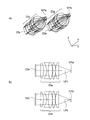
図2に示したルーペ光学系の好ましい具体例を説明する。図3はルーペ光学系を示す図であって、(a)は斜視図、(b)はz軸方向に沿う断面図である。図3に示すように、観察ユニット20は、表示素子とルーペ光学系とを、それぞれ2つ有する。図3に示すルーペ光学系は、後述の実施例1のルーペ光学系である。
A preferred specific example of the loupe optical system shown in FIG. 2 will be described. 3A and 3B are diagrams showing a loupe optical system, in which FIG. 3A is a perspective view and FIG. 3B is a cross-sectional view along the z-axis direction. As shown in FIG. 3, the
観察ユニット20は、表示素子22aとは別に、表示素子22bを有すると共に、ルーペ光学系23aとは別に、ルーペ光学系23bを有する。表示素子22aとルーペ光学系23aは、第1の光路LP1に配置されている。また、表示素子22bとルーペ光学系23bは、第2の光路LP2に配置されている。このようにルーペ光学系23aとルーペ光学系23bは、並んで配置されている。また、表示素子22aと表示素子22bも、並んで配置されている。なお、光路は、アイポイントEPの中心と、表示素子22の中心を結んだ線で定義される。
The
また、ルーペ光学系23aの光軸(中心軸)とアイポイントEPaの中心は、一致している。同様に、ルーペ光学系23bの光軸(中心軸)とアイポイントEPbの中心も、一致している。また、第1の光路LP1と第2の光路LP2は、平行となっている。また、第1の光路LP1と第2の光路LP2の間隔は、観察者の平均的な眼幅と同じである。
Further, the optical axis (center axis) of the loupe
図4は、図3に示すルーペ光学系とは別のルーペ光学系を示す図であって、z軸方向に沿う断面図である。図4に示すルーペ光学系は、後述の実施例2のルーペ光学系である。図4に示すように、表示素子24aとルーペ光学系25aは、第1の光路LP1に配置されている。また、表示素子24bとルーペ光学系25bは、第2の光路LP2に配置されている。このように、ルーペ光学系25aとルーペ光学系25bは、並んで配置されている。また、表示素子24aと表示素子24bも、並んで配置されている。
4 is a view showing a loupe optical system different from the loupe optical system shown in FIG. 3, and is a cross-sectional view taken along the z-axis direction. The loupe optical system shown in FIG. 4 is a loupe optical system of Example 2 described later. As shown in FIG. 4, the
なお、第1実施形態における観察ユニットは、表示素子とルーペ光学系を、それぞれ2つ有するものの、反射部材は有していない。このような構成の場合、以下の条件式(4)を満足することが好ましい。
12mm<fl≦50mm (4)
ここで、
flはルーペ光学系の焦点距離、
である。
Note that the observation unit in the first embodiment has two display elements and two loupe optical systems, but does not have a reflecting member. In such a configuration, it is preferable that the following conditional expression (4) is satisfied.
12mm <f l ≦ 50mm (4 )
here,
f l is the focal length of the loupe optical system,
It is.
なお、観察ユニット20に、2つのルーペ光学系の間隔を変化させる調節機構を設けても良い。このようにすれば、観察者に応じて、ルーペ光学系23aとルーペ光学系23bとの間隔、すなわち、アイポイントEPaとアイポイントEPbの間隔を、調節することができる。このような調節機構は、後述の第2〜第4実施形態の顕微鏡システムにも設けて良い。
The
また、2つのルーペ光学系のうちの、少なくとも一方を、その光軸方向に沿って移動させる移動機構を有することが好ましい。このようにすれば、ピントの調節が容易になる。このような移動機構は、後述の第2〜第4実施形態の顕微鏡システムにも設けて良い。 Moreover, it is preferable to have a moving mechanism that moves at least one of the two loupe optical systems along the optical axis direction. In this way, the focus can be easily adjusted. Such a moving mechanism may be provided in the microscope systems of the second to fourth embodiments described later.
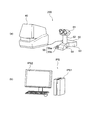
第2実施形態の顕微鏡システムを、図5、6を用いて説明する。図5(a)は顕微鏡システムの概観図、(b)は画像処理ユニットの概観図、図6は顕微鏡システムにおける顕微鏡の構成を示す図である。 A microscope system according to the second embodiment will be described with reference to FIGS. 5A is an overview diagram of the microscope system, FIG. 5B is an overview diagram of the image processing unit, and FIG. 6 is a diagram illustrating a configuration of the microscope in the microscope system.
図5(a)に示すように、顕微鏡システム200は、顕微鏡40と、観察ユニット50と、を備えている。なお、必要に応じて、顕微鏡システム200に、図5(b)に示すような画像処理システムIPSを組み合わせても良い。この画像処理ユニットIPSは、画像処理装置IPS1と表示装置IPS2を備えている。
As shown in FIG. 5A, the
顕微鏡40は、図6に示すように、光源ユニット41と、ステージ42と、ホルダ43と、顕微鏡対物レンズ44と、レボルバ45と、結像光学系46と、撮像光学系47と、撮像装置60と、を備えている。また、撮像装置60は、撮像素子61と、制御装置(第1制御装置)62と、を備えている。なお、顕微鏡40の基本的な構成は、第1実施形態における顕微鏡10と同様であるため、各構成の説明は省略する。
As shown in FIG. 6, the
本実施形態における観察ユニット50は、顕微鏡40と別体で、顕微鏡40に対して着脱できない。よって、観察ユニット50は、顕微鏡40とは分離して使用される。そして、観察ユニット50では、表示装置に標本の画像を表示して、画像を観察者が観察する。そのため、本実施形態の顕微鏡システムでは、標本の画像データ取得するために、顕微鏡40は撮像装置60を必ず有している。
The
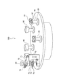
観察ユニット50は、接眼部51と、支柱52と、ベース53と、第1の操作部54と、第2の操作部55と、を有する。ベース53に、支柱52と、第1の操作部54と、第2の操作部55と、が接続され、支柱52に接眼部51が接続されている。
The
第1の操作部54と第2の操作部55は、いずれも回転式のつまみである。第1の操作部54のつまみを回転させることで、顕微鏡40において、標本にピントを合わせることができる。また、第2の操作部55のつまみを回転させることで、顕微鏡40において、標本を移動させることができる。なお、直交する2方向に標本の移動ができるように、第2の操作部55には、2つのつまみ55a、55bが設けられている。観察者は、接眼部51を覗きながら第1の操作部54と第2の操作部55を操作することで、標本のピント合わせと、観察位置の調節を行うことができる。
The
観察ユニット50の接眼部51の構造を、図7を用いて説明する。図7は接眼部51の構成を示す図である。接眼部51は、制御装置(第2制御装置)56と、表示素子57と、ミラー(反射部材)58と、ルーペ光学系59と、を有する。
The structure of the
表示素子57は制御装置56に接続されている。制御装置56は、撮像装置60の制御装置62との間で通信を行なう。この通信は、有線であっても、無線であっても構わない。また、ルーペ光学系59は、表示素子57から所定の間隔をおいて配置されている。更に、表示素子57とルーペ光学系59との間に、ミラー58が配置されている。よって、表示素子57に表示された画像の光はミラー58で反射され、ルーペ光学系59に入射することになる。
The
上述のように、撮像装置60によって、標本の画像データが取得される。取得された標本の画像データは、制御装置62と制御装置56を介して表示素子57に入力される。これにより、表示素子57に、標本の画像が表示される。そして、観察者は、この表示された標本の画像を、ミラー58とルーペ光学系59を介して肉眼で観察する。このように、観察ユニット50では標本の画像、すなわち、デジタル画像を観察する点が、標本の光学像を観察していた従来の双眼鏡筒と異なる。
As described above, the image data of the specimen is acquired by the
本実施形態の顕微鏡システムでは、標本の画像を観察するために必要な光学部品は、ミラー58とルーペ光学系59のみである。このように、本実施形態の顕微鏡システムでは、使用される光学部品が従来の双眼鏡筒に比べて少ないので、諸収差の悪化、色再現性の低下、像の明るさの低下を防止することできる。
In the microscope system of this embodiment, only the
また、観察者は観察ユニット50を介して標本の画像を観察する。この場合、観察ユニット50(アイポイントEP)に対して、観察者の目の位置を一定に保つことができる。そのため、一定の観察倍率が維持できると共に、没入感が得られることから、集中して長時間の観察が可能となる。
Further, the observer observes the sample image through the
なお、第1実施形態の顕微鏡システムと同様に、本実施形態の顕微鏡システムにおいても、アイポイントの位置や仰角を調節する機構を設けることができる。例えば、接眼部51を2つの構造体とし、一方の構造体に表示素子57、ミラー58及びルーペ光学系59を配置する。そして、一方の構造体を、他方の構造体に対して回転させることで、仰角の調節を行なうことができる(矢印C)。また、支柱52の長さを変更できるようにすれば、アイポイントの位置を垂直方向に移動させることができる(矢印D)。また、接眼部51と支柱52との接続部にスライド機構を設ければ、アイポイントの位置を水平方向に移動させることができる(矢印E)。
Similar to the microscope system of the first embodiment, the microscope system of the present embodiment can also be provided with a mechanism for adjusting the position of the eye point and the elevation angle. For example, the
図7に示したルーペ光学系の好ましい具体例を説明する。図8はルーペ光学系を示す図であって、(a)は斜視図、(b)はz軸方向に沿う断面図である。図8に示すように、観察ユニット50の接眼部51は、表示素子と、ミラー(反射部材)と、ルーペ光学系とを、それぞれ2つ有する。図8に示すルーペ光学系は、後述の実施例3のルーペ光学系である。
A preferred specific example of the loupe optical system shown in FIG. 7 will be described. 8A and 8B are diagrams showing the loupe optical system, in which FIG. 8A is a perspective view and FIG. 8B is a cross-sectional view along the z-axis direction. As shown in FIG. 8, the
観察ユニット50は、表示素子57aとは別に、表示素子57bを有し、ミラー58aとは別に、ミラー58bを有し、更に、ルーペ光学系59aとは別に、ルーペ光学系59bを有する。表示素子57aと、ミラー58aと、ルーペ光学系59aは、第1の光路LP1に配置されている。また、表示素子57bと,ミラー58bと、ルーペ光学系59bは、第2の光路LP2に配置されている。このようにルーペ光学系23aとルーペ光学系23bは、並んで配置されている。また、表示素子22aと表示素子22b、ミラー58aとミラー58bも、並んで配置されている。
The
また、ルーペ光学系59aの光軸(中心軸)とアイポイントEPaの中心は、一致している。同様に、ルーペ光学系59bの光軸(中心軸)とアイポイントEPbの中心も、一致している。また、第1の光路LP1と第2の光路LP2は、平行となっている。また、第1の光路LP1と第2の光路LP2の間隔は、観察者の平均的な眼幅と同じである。
Further, the optical axis (center axis) of the loupe
なお、第2実施形態における観察ユニットは、表示素子、反射部材及びルーペ光学系を、それぞれ2つ有する。このような構成の場合、以下の条件式(5)を満足することが好ましい。
50mm<fl<150mm (5)
ここで、
flはルーペ光学系の焦点距離、
である。
Note that the observation unit in the second embodiment has two display elements, reflecting members, and a loupe optical system. In such a configuration, it is preferable that the following conditional expression (5) is satisfied.
50mm < fl <150mm (5)
here,
f l is the focal length of the loupe optical system,
It is.
本実施形態における観察ユニット50は、第1実施形態の観察ユニット20と同様に、表示素子とルーペ光学系を備え、観察者は、表示素子に表示された画像をルーペ光学系で観察する。よって、本実施形態の顕微鏡システムにおいても、第1実施形態の顕微鏡システムと同様の作用効果を奏する。
Similar to the
なお、顕微鏡システム200に画像処理ユニットIPSを組み合わせた場合、顕微鏡40の撮像装置60で取得した画像を、画像処理装置IPS1を経由して、観察ユニット50に出力することができる。そのため、画像処理装置IPS1において、画像データに対して各種の画像処理を施すことができる。また、観察ユニット50で観察している画像を、表示装置IPS2に表示させることもできる。
When the image processing unit IPS is combined with the
第3実施形態の顕微鏡システムを、図9、10を用いて説明する。図9は顕微鏡システムの概観図、図10は観察ユニット(接眼部)の構成を示す図である。 A microscope system according to the third embodiment will be described with reference to FIGS. FIG. 9 is a schematic view of the microscope system, and FIG. 10 is a diagram showing the configuration of the observation unit (eyepiece).
図9に示すように、顕微鏡システム300は、顕微鏡70と、観察ユニット80と、を備えている。顕微鏡70は、光源ユニット71と、顕微鏡対物レンズ72と、レボルバ73と、ステージ74と、撮像光学系75と、双眼鏡筒76と、撮像装置90と、を備える。また、撮像装置90は、撮像素子と、制御装置(第1制御装置)と、を備えているが、図9では図示されていない。なお、顕微鏡70の基本的な構成は、第1実施形態における顕微鏡10と同様であるため、各構成の説明は省略する。
As shown in FIG. 9, the
本実施形態における観察ユニット80は、顕微鏡70と別体で、顕微鏡70に対して着脱できない。よって、観察ユニット80は、顕微鏡70とは分離して使用される。そして、観察ユニット80では、表示装置に標本の画像を表示して、画像を観察者が観察する。そのため、本実施形態の顕微鏡システムでは、標本の画像データ取得するために、顕微鏡70は撮像装置90を必ず有している。
The
観察ユニット80は、接眼部81と、支柱82と、ベース83と、を有する。ベース83に支柱82が接続され、支柱82に接眼部81が接続されている。
The
観察ユニット80の接眼部81の構造を、図10を用いて説明する。接眼部81は、制御装置(第2制御装置)84と、表示素子85と、ルーペ光学系86と、を有する。
The structure of the
表示素子85は制御装置84に接続されている。制御装置84は、撮像装置90の制御装置との間で通信を行なう。この通信は、有線であっても、無線であっても構わない。また、ルーペ光学系86は、表示素子85から所定の間隔をおいて配置されている。
The
上述のように、撮像装置90によって、標本の画像データが取得される。取得された標本の画像データは、制御装置と制御装置84を介して表示素子85に入力される。これにより、表示素子85に、標本の画像が表示される。そして、観察者は、この表示された標本の画像を、ルーペ光学系86を介して肉眼で観察する。このように、観察ユニット80では標本の画像、すなわち、デジタル画像を観察する点が、標本の光学像を観察していた従来の双眼鏡筒と異なる。
As described above, the image data of the specimen is acquired by the
本実施形態の顕微鏡システムでは、標本の画像を観察するために必要な光学部品は、ルーペ光学系86のみである。このように、本実施形態の顕微鏡システムでは、使用される光学部品が従来の双眼鏡筒に比べて少ないので、諸収差の悪化、色再現性の低下、像の明るさの低下を防止することできる。
In the microscope system of the present embodiment, the loupe
また、観察者は観察ユニット80を介して標本の画像を観察する。この場合、観察ユニット80(アイポイントEP)に対して、観察者の目の位置を一定に保つことができる。そのため、一定の観察倍率が維持できると共に、没入感が得られることから、集中して長時間の観察が可能となる。
Further, the observer observes the sample image through the
なお、第1、第2実施形態の顕微鏡システムと同様に、本実施形態の顕微鏡システムにおいても、アイポイントの位置や仰角を調節する機構を設けることができる。 Similar to the microscope systems of the first and second embodiments, the microscope system of the present embodiment can also be provided with a mechanism for adjusting the position and elevation angle of the eye point.
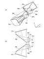
図10に示したルーペ光学系の好ましい具体例を説明する。図11はルーペ光学系を示す図であって、(a)は斜視図、(b)はz軸方向に沿う断面図である。図11に示すように、観察ユニット80の接眼部81は、1つの表示素子と、2つのルーペ光学系と、を有する。図11に示すルーペ光学系は、後述の実施例4のルーペ光学系である。
A preferred specific example of the loupe optical system shown in FIG. 10 will be described. 11A and 11B are diagrams illustrating a loupe optical system, in which FIG. 11A is a perspective view and FIG. 11B is a cross-sectional view along the z-axis direction. As shown in FIG. 11, the
接眼部81は、ルーペ光学系86aとは別に、ルーペ光学系86bを有する。ルーペ光学系86aは、第1の光路LP1に配置されている。また、ルーペ光学系86bは、第2の光路LP2に配置されている。このようにルーペ光学系86aとルーペ光学系86bは、並んで配置されている。そして、表示素子85は、第1の光路LP1と第2の光路LP2を含むように、配置されている。
The
また、ルーペ光学系86aの光軸(中心軸)とアイポイントEPaの中心は、一致していない。アイポイントEPaの中心は、ルーペ光学系86aの光軸よりも外側に位置している。同様に、ルーペ光学系86bの光軸(中心軸)とアイポイントEPbの中心は、一致していない。アイポイントEPbの中心は、ルーペ光学系86bの光軸よりも外側に位置している。
Further, the optical axis (center axis) of the loupe
なお、第1の光路LP1と第2の光路LP2は、非平行となっている。また、第1の光路LP1と第2の光路LP2の間隔は、観察者の平均的な眼幅と同じである。 The first optical path LP1 and the second optical path LP2 are not parallel. Further, the distance between the first optical path LP1 and the second optical path LP2 is the same as the average eye width of the observer.
なお、第3実施形態における観察ユニットは、1つの表示素子と2つのルーペ光学系を有するものの、反射部材は有していない。このような構成の場合、以下の条件式(6)を満足することが好ましい。
100mm<fl<300mm (6)
ここで、
flはルーペ光学系の焦点距離、
である。
Note that the observation unit in the third embodiment has one display element and two loupe optical systems, but does not have a reflecting member. In such a configuration, it is preferable that the following conditional expression (6) is satisfied.
100 mm < fl <300 mm (6)
here,
f l is the focal length of the loupe optical system,
It is.
本実施形態における観察ユニット80は、第1実施形態の観察ユニット20と同様に、表示素子とルーペ光学系を備え、観察者は、表示素子に表示された画像をルーペ光学系で観察する。よって、本実施形態の顕微鏡システムにおいても、第1実施形態の顕微鏡システムと同様の作用効果を奏する。
Similar to the
また、本実施形態の顕微鏡システムは、観察ユニット80を複数有している。ここで、顕微鏡70と各観察ユニット80との間や、観察ユニット80同士の間には、光学部品が存在しない。このように、本実施形態の顕微鏡システムでは、使用される光学部品が従来の双眼鏡筒に比べて少ないので、諸収差の悪化、色再現性の低下、像の明るさの低下を防止することできる。
Further, the microscope system of the present embodiment has a plurality of
また、顕微鏡70と各観察ユニット80との間には、両者の位置を規制する構造物がない。また、観察ユニット80同士の間にも、互いの位置を規制する構造物がない。そのため、顕微鏡70、各観察ユニット80は、いずれも自由に配置することができる。
In addition, there is no structure that restricts the position between the
そして、各観察ユニット80には、撮像装置90で取得した標本の画像が表示される。よって、複数の観察者が、同じ標本を観察することができる。ここで、上述のように、顕微鏡70、各観察ユニット80は、いずれも自由に配置することができる。そのため、各観察者は窮屈な姿勢を強いられることがない。
Each
第4実施形態の顕微鏡システムを、図12を用いて説明する。なお、本実施形態の顕微鏡システムでは、顕微鏡は、第2実施形態の顕微鏡、又は第3実施形態の顕微鏡を用いる。そのため、図12には、観察ユニットのみを図示している。また、観察ユニットには、第3実施形態におけるルーペ光学系を用いているため、ルーペ光学系の構成は図示されていない。 A microscope system according to the fourth embodiment will be described with reference to FIG. In the microscope system of this embodiment, the microscope of the second embodiment or the microscope of the third embodiment is used as the microscope. Therefore, only the observation unit is shown in FIG. Since the observation unit uses the loupe optical system in the third embodiment, the configuration of the loupe optical system is not shown.
本実施形態における観察ユニット500は、本体部501と、表示素子502と、を有する。本体部501には、ルーペ光学系86aと86bが設けられている。表示素子502は、本体部501に対して着脱可能になっている。そのため、本体部501には、表示素子502を装着するための、装着部(溝)503が設けられている。また、表示素子502としては、携帯型の情報端末を用いることができる。そのため、情報端末の利用用途が広がる。
The
また、本実施形態における観察ユニット500は、第1実施形態の観察ユニット20と同様に、表示素子とルーペ光学系を備え、観察者は、表示素子に表示された画像をルーペ光学系で観察する。よって、本実施形態の顕微鏡システムにおいても、第1実施形態の顕微鏡システムと同様の作用効果を奏する。また、第4実施形態における観察ユニットも、条件(6)を満足することが好ましい。
In addition, the
また、本実施形態の観察ユニットは、入力された所定の画像を表示する表示素子と、表示素子から所定の間隔をおいて配置されたルーペ光学系と、を有し、所定の画像が、顕微鏡対物レンズを介して形成された像を撮像素子で撮像した画像であって、以下の条件式(1A)と(1B)のいずれか一方と、条件式(2)を満足することを特徴とする。
0.9×βoc<(Ld/Li)×(250/fl)<1.1×βoc (1A)
0.9×βoc<q×(Ld/Li)×(250/fl)<1.1×βoc (1B)
20°<tan-1(Ld/(2×fl))<35° (2)
ここで、
βocは光学像を観察する際の接眼レンズの倍率、
qは中間結像レンズの倍率、
Ldは表示素子の表示範囲の対角長、
Liは撮像素子の撮像範囲の対角長、
flはルーペ光学系の焦点距離、
である。
The observation unit according to the present embodiment includes a display element that displays an input predetermined image, and a loupe optical system that is disposed at a predetermined interval from the display element. An image obtained by imaging an image formed through an objective lens with an imaging device, wherein any one of the following conditional expressions (1A) and (1B) and conditional expression (2) are satisfied .
0.9 × β oc <(L d / L i ) × (250 / fl ) <1.1 × β oc (1A)
0.9 × β oc <q × (L d / L i ) × (250 / fl ) <1.1 × β oc (1B)
20 ° <tan −1 (L d / (2 × f 1 )) <35 ° (2)
here,
β oc is the magnification of the eyepiece when observing the optical image,
q is the magnification of the intermediate imaging lens,
L d is the diagonal length of the display range of the display element,
L i is the diagonal length of the imaging range of the image sensor,
f l is the focal length of the loupe optical system,
It is.
本実施形態の観察ユニットによれば、高い光学性能を有し、観察倍率を一定に保つことができ、集中して長時間の観察が可能な観察ユニットを提供することができる。また、移動機構や調節機構を設ける場合に、これらの機構を簡素にできる観察ユニットを提供することができる。 According to the observation unit of this embodiment, it is possible to provide an observation unit that has high optical performance, can keep the observation magnification constant, and can concentrate and observe for a long time. In addition, when a moving mechanism and an adjusting mechanism are provided, an observation unit that can simplify these mechanisms can be provided.
以下、ルーペ光学系の実施例1〜4について説明する。実施例1〜4に係るルーペ光学系の光学構成を示す光軸に沿う断面を、それぞれ図13(a)〜図16(a)に示す。これらの断面図中、L1〜L6は各レンズ、EPはアイポイントを示してている。また、紙面左側を物体側、右側を像側とする。 Hereinafter, Examples 1 to 4 of the loupe optical system will be described. Cross sections along the optical axis showing the optical configuration of the loupe optical systems according to Examples 1 to 4 are shown in FIGS. 13 (a) to 16 (a), respectively. In these cross-sectional views, L1 to L6 indicate lenses, and EP indicates an eye point. Also, the left side of the paper is the object side and the right side is the image side.
実施例1のルーペ光学系は、平凸正レンズL1と、両凹負レンズL2と、両凸正レンズL3と、両凸正レンズL4と、平凸正レンズL5と、からなる。ここで、両凹負レンズL2と両凸正レンズL3とが接合されている。 The loupe optical system of Example 1 includes a planoconvex positive lens L1, a biconcave negative lens L2, a biconvex positive lens L3, a biconvex positive lens L4, and a planoconvex positive lens L5. Here, the biconcave negative lens L2 and the biconvex positive lens L3 are cemented.
実施例2のルーペ光学系は、像側に凸面を向けた正メニスカスレンズL1と、像側に凸面を向けた負メニスカスレンズL2と、両凸正レンズL3と、物体側に凸面を向けた正メニスカスレンズL4と、平凸正レンズL5と、平凹負レンズL6と、からなる。ここで、正メニスカスレンズL1と負メニスカスレンズL2とが接合されている。また、平凸正レンズL5と平凹負レンズL6とが接合されている。 The loupe optical system of Example 2 includes a positive meniscus lens L1 having a convex surface facing the image side, a negative meniscus lens L2 having a convex surface facing the image side, a biconvex positive lens L3, and a positive surface having a convex surface facing the object side. It consists of a meniscus lens L4, a plano-convex positive lens L5, and a plano-concave negative lens L6. Here, the positive meniscus lens L1 and the negative meniscus lens L2 are cemented. The planoconvex positive lens L5 and the planoconcave negative lens L6 are cemented.
実施例3のルーペ光学系は、両凸正レンズL1と、像側に凸面を向けた負メニスカスレンズL2と、からなる。ここで、両凸正レンズL1と負メニスカスレンズL2とが接合されている。 The loupe optical system of Example 3 includes a biconvex positive lens L1 and a negative meniscus lens L2 having a convex surface facing the image side. Here, the biconvex positive lens L1 and the negative meniscus lens L2 are cemented.
実施例4のルーペ光学系は、物体側に凸面を向けた正メニスカスレンズL1と、物体側に凸面を向けた負メニスカスレンズL2と、からなる。ここで、正メニスカスレンズL1と負メニスカスレンズL2とが接合されている。 The loupe optical system of Example 4 includes a positive meniscus lens L1 having a convex surface facing the object side and a negative meniscus lens L2 having a convex surface facing the object side. Here, the positive meniscus lens L1 and the negative meniscus lens L2 are cemented.
次に、上記各実施例のルーペ光学系を構成する光学部材の数値データを掲げる。なお、各実施例の数値データにおいて、r1、r2、…は各レンズ面の曲率半径、d1、d2、…は各レンズの肉厚または空気間隔、nd1、nd2、…は各レンズのd線での屈折率、νd1、νd2、…は各レンズのアッべ数、fは焦点距離、NA’は開口数、EPLは、レンズ最終面からアイポイントまでの距離を示している。 Next, numerical data of optical members constituting the loupe optical system of each of the above embodiments will be listed. In the numerical data of each embodiment, r1, r2,... Are the curvature radii of the lens surfaces, d1, d2,... Are the thickness or air spacing of each lens, and nd1, nd2,. Are the Abbe number of each lens, f is the focal length, NA ′ is the numerical aperture, and EPL is the distance from the last lens surface to the eye point.
また、物面には表示素子が配置されている。また、像高は、ルーペ光学系と理想レンズとによって像を形成したときの像の高さである。理想レンズは、ルーペ光学系の像側(アイポイント側)に配置され、焦点距離は25mmである。また、NA’は、理想レンズを配置した時の像側における開口数である。 A display element is arranged on the object surface. The image height is the image height when an image is formed by the loupe optical system and the ideal lens. The ideal lens is disposed on the image side (eye point side) of the loupe optical system and has a focal length of 25 mm. NA ′ is the numerical aperture on the image side when the ideal lens is disposed.
数値実施例1
単位mm
面データ
面番号 r d nd νd
物面 ∞ 8.45
1 ∞ 4.80 1.7859 44.2
2 -31.253 4.94
3 -21.275 2.81 1.8052 25.4
4 39.37 7.40 1.6516 58.6
5 -39.37 0.18
6 100.551 4.50 1.7440 44.8
7 -59.027 0.18
8 29.478 5.40 1.5688 56.4
9 ∞
各種データ
f 25
NA’ 0.12
像高 11.4
瞳半径 3
EPL 21
Numerical example 1
Unit mm
Surface data Surface number rd nd νd
Surface ∞ 8.45
1 ∞ 4.80 1.7859 44.2
2 -31.253 4.94
3 -21.275 2.81 1.8052 25.4
4 39.37 7.40 1.6516 58.6
5 -39.37 0.18
6 100.551 4.50 1.7440 44.8
7 -59.027 0.18
8 29.478 5.40 1.5688 56.4
9 ∞
Various data f 25
NA '0.12
Statue height 11.4
数値実施例2
単位mm
面データ
面番号 r d nd νd
物面 ∞ 9.13
1 -53.774 27.91 1.5750 41.5
2 -30.872 4.50 1.6433 48.0
3 -56.704 0.19
4 141.445 10.81 1.6138 56.4
5 -117.503 0.19
6 54.814 9.89 1.6138 56.4
7 688.631 0.19
8 28.793 11.25 1.6138 56.4
9 ∞ 1.35 1.698951 30.1
10 31.975
各種データ
f 31.5
NA’ 0.16
像高 16.7
瞳半径 4
EPL 20
Numerical example 2
Unit mm
Surface data Surface number rd nd νd
Surface ∞ 9.13
1 -53.774 27.91 1.5750 41.5
2 -30.872 4.50 1.6433 48.0
3 -56.704 0.19
4 141.445 10.81 1.6138 56.4
5 -117.503 0.19
6 54.814 9.89 1.6138 56.4
7 688.631 0.19
8 28.793 11.25 1.6138 56.4
9 ∞ 1.35 1.698951 30.1
10 31.975
Various data f 31.5
NA '0.16
Statue height 16.7
Pupil radius 4
数値実施例3
単位mm
面データ
面番号 r d nd νd
物面 ∞ 117.8
1 72.200 13.7 1.5163 64.1
2 -53.9 4.0 1.6477 33.8
3 -173.889
各種データ
f 120.3
NA’ 0.2
像高 12.7
瞳半径 5
EPL 30
Numerical Example 3
Unit mm
Surface data Surface number rd nd νd
Object ∞ 117.8
1 72.200 13.7 1.5163 64.1
2 -53.9 4.0 1.6477 33.8
3 -173.889
Various data f 120.3
NA '0.2
Statue height 12.7
数値実施例4
単位mm
面データ
面番号 r d nd νd
物面 ∞ 117.8
1 41.732 12.0 1.5952 67.7
2 189.230 4.0 1.7205 34.7
3 56.966
各種データ
f 250
NA’ 0.2
像高 12.1
瞳半径 5
EPL 30
Numerical Example 4
Unit mm
Surface data Surface number rd nd νd
Object ∞ 117.8
1 41.732 12.0 1.5952 67.7
2 189.230 4.0 1.7205 34.7
3 56.966
Various data f 250
NA '0.2
Statue height 12.1
また、実施例1〜4にかかるルーペ光学系の収差図を、それぞれ図13(b)、(c)、(d)〜図16(b)、(c)、(d)に示す。これらの収差図において、”FIY”は像高である。また、(b)、(c)、(d)は、それぞれ、球面収差(SA)、非点収差(AS)、歪曲収差(DT)を示している。なお、これらの収差図は、ルーペ光学系と理想レンズとによって像を形成したときの収差図である。 In addition, aberration diagrams of the loupe optical systems according to Examples 1 to 4 are shown in FIGS. 13B, 13C, and 13D, respectively, to FIGS. 16B, 16C, and 16D. In these aberration diagrams, “FIY” is the image height. Also, (b), (c), and (d) show spherical aberration (SA), astigmatism (AS), and distortion aberration (DT), respectively. These aberration diagrams are aberration diagrams when an image is formed by the loupe optical system and the ideal lens.
次に、各実施例における条件式(1B)、(2)の値を掲げる。
条件式 実施例1 実施例2 実施例3 実施例4
(1B)q×(Ld/Li)×(250/fl ) 10 11.31 10.50 10.1
(2)tan-1(Ld/(2×fl)) 24.5 33.7 25.5 24.7
Next, the values of conditional expressions (1B) and (2) in each example will be listed.
Conditional Example Example 1 Example 2 Example 3 Example 4
(1B) q × (L d / L i ) × (250 / f l ) 10 11.31 10.50 10.1
(2) tan -1 (L d / (2 × f l )) 24.5 33.7 25.5 24.7
また、各実施例における要素値を掲げる。
要素値 実施例1 実施例2 実施例3 実施例4
βoc 10 10 10 10
q 0.5 0.35 0.5 0.5
Ld 22.8 42 115 230
Li 11.4 13 11.4 11.4
fl 25 31.5 120.3 250
In addition, element values in each example are listed.
Element Value Example 1 Example 2 Example 3 Example 4
q 0.5 0.35 0.5 0.5
L d 22.8 42 115 230
L i 11.4 13 11.4 11.4
f l 25 31.5 120.3 250
なお、本発明は、その趣旨を逸脱しない範囲で様々な変形例をとることができる。 The present invention can take various modifications without departing from the spirit of the present invention.
以上のように、本発明は、高い光学性能を有し、観察倍率を一定に保つことができ、集中して長時間の観察が可能な顕微鏡システムや、移動機構や調節機構を設ける場合に、これらの機構を簡素にできる顕微鏡システムに適している。 As described above, the present invention has a high optical performance, the observation magnification can be kept constant, and a microscope system capable of intensive observation for a long time, a moving mechanism, and an adjustment mechanism are provided. It is suitable for a microscope system that can simplify these mechanisms.
1 光源ユニット
2 ハーフミラー
3 顕微鏡対物レンズ
4 レボルバ
5 ステージ
6 結像光学系
7 ミラー
8 アフォーカル光学系
9 撮像光学系
10 顕微鏡
20 観察ユニット
21 制御装置(第2制御装置)
22、22a、22b 表示素子
23、23a、23b ルーペ光学系
24a、24b 表示素子
25a、25b ルーペ光学系
30 撮像装置
31 撮像素子
32 制御装置(第1制御装置)
40 顕微鏡
41 光源ユニット
42 ステージ
43 ホルダ
44 顕微鏡対物レンズ
45 レボルバ
46 結像光学系
47 撮像光学系
50 観察ユニット
51 接眼部
52 支柱
53 ベース
54 第1の操作部
55 第2の操作部
55a、55b つまみ
56 制御装置(第2制御装置)
57、57a、57b 表示素子
58、58a、58b ミラー(反射部材)
59、59a、59b ルーペ光学系
60 撮像装置
61 撮像素子
62 制御装置(第1制御装置)
70 顕微鏡
71 光源ユニット
72 顕微鏡対物レンズ
73 レボルバ
74 ステージ
75 双眼鏡筒
76 撮像光学系
80 観察ユニット
81 接眼部
82 支柱
83 ベース
84 制御装置(第2制御装置)
85 表示素子
86、86a、86b ルーペ光学系
90 撮像装置
100 顕微鏡システム
200 顕微鏡システム
300 顕微鏡システム
500 観察ユニット
501 本体部
502 表示素子
503 装着部(溝)
EP、EPa、EPb アイポイント
IPS 画像処理システム
IPS1 画像処理装置
IPS2 表示装置
LPa 観察光路
LPb 撮像光路
LP1 第1の光路
LP2 第2の光路
DESCRIPTION OF
22, 22a,
40
57, 57a,
59, 59a, 59b Loupe
85
EP, EPa, EPb Eye point IPS Image processing system IPS1 Image processing device IPS2 Display device LPa Observation optical path LPb Imaging optical path LP1 First optical path LP2 Second optical path
Claims (19)
前記顕微鏡は、顕微鏡対物レンズと、該顕微鏡対物レンズを介して形成された像位置に配置された撮像素子と、該撮像素子に接続された第1制御装置と、を有し、
前記観察ユニットは、第2制御装置と、該第2制御装置に接続された表示素子と、該表示素子から所定の間隔をおいて配置されたルーペ光学系と、を有し、
更に、前記第1制御装置と前記第2制御装置との間で通信を行なう通信手段を備え、
前記撮像素子で取得した画像を前記表示素子に表示することを特徴とする顕微鏡システム。 A microscope system comprising a microscope and an observation unit provided separately from the microscope,
The microscope includes a microscope objective lens, an image sensor disposed at an image position formed via the microscope objective lens, and a first control device connected to the image sensor.
The observation unit includes a second control device, a display element connected to the second control device, and a loupe optical system disposed at a predetermined interval from the display element,
Furthermore, it comprises a communication means for performing communication between the first control device and the second control device,
A microscope system, wherein an image acquired by the imaging element is displayed on the display element.
0.9×βoc<(Ld/Li)×(250/fl)<1.1×βoc (1A)
20°<tan-1(Ld/(2×fl))<35° (2)
ここで、
βocは光学像を観察する際の接眼レンズの倍率、
Ldは前記表示素子の表示範囲の対角長、
Liは前記撮像素子の撮像範囲の対角長、
flは前記ルーペ光学系の焦点距離、
である。 The microscope system according to claim 1, wherein the following conditional expressions (1A) and (2) are satisfied.
0.9 × β oc <(L d / L i ) × (250 / fl ) <1.1 × β oc (1A)
20 ° <tan −1 (L d / (2 × f 1 )) <35 ° (2)
here,
β oc is the magnification of the eyepiece when observing the optical image,
L d is the diagonal length of the display range of the display element,
L i is the diagonal length of the imaging range of the imaging device,
f l is the focal length of the loupe optical system,
It is.
以下の条件式(1B)、(2)を満足することを特徴とする請求項1に記載の顕微鏡システム。
0.9×βoc<q×(Ld/Li)×(250/fl)<1.1×βoc (1B)
20°<tan-1(Ld/(2×fl))<35° (2)
ここで、
βocは光学像を観察する際の接眼レンズの倍率、
qは前記中間結像レンズの倍率、
Ldは前記表示素子の表示範囲の対角長、
Liは前記撮像素子の撮像範囲の対角長、
flは前記ルーペ光学系の焦点距離、
である。 Between the microscope objective lens and the image sensor, an intermediate imaging lens is provided,
The microscope system according to claim 1, wherein the following conditional expressions (1B) and (2) are satisfied.
0.9 × β oc <q × (L d / L i ) × (250 / fl ) <1.1 × β oc (1B)
20 ° <tan −1 (L d / (2 × f 1 )) <35 ° (2)
here,
β oc is the magnification of the eyepiece when observing the optical image,
q is the magnification of the intermediate imaging lens,
L d is the diagonal length of the display range of the display element,
L i is the diagonal length of the imaging range of the imaging device,
f l is the focal length of the loupe optical system,
It is.
8≦βoc≦30 (3)
ここで、
βocは光学像を観察する際の接眼レンズの倍率、
である。 The microscope system according to claim 2 or 3, wherein the following conditional expression (3) is satisfied.
8 ≦ β oc ≦ 30 (3)
here,
β oc is the magnification of the eyepiece when observing the optical image,
It is.
前記表示素子と、前記ルーペ光学系と、が第1の光路に配置され、
前記別の表示素子と、前記別のルーペ光学系と、が第2の光路に配置され、
前記ルーペ光学系と、前記別のルーペ光学系とが、並んで配置されていることを特徴とする請求項1から4のいずれか1項に記載の顕微鏡システム。 The observation unit further includes a display element different from the display element, and a loupe optical system different from the loupe optical system,
The display element and the loupe optical system are disposed in a first optical path,
The another display element and the another loupe optical system are disposed in a second optical path,
The microscope system according to any one of claims 1 to 4, wherein the loupe optical system and the another loupe optical system are arranged side by side.
12mm<fl≦50mm (4)
ここで、
flは前記ルーペ光学系の焦点距離、
である。 The microscope system according to any one of claims 1 to 5, wherein the following conditional expression (4) is satisfied.
12mm <f l ≦ 50mm (4 )
here,
f l is the focal length of the loupe optical system,
It is.
前記反射部材は、前記表示素子からの光を、前記ルーペ光学系に向けて反射する位置に配置されていることを特徴とする請求項1から4のいずれか1項に記載の顕微鏡システム。 The observation unit has a reflecting member,
5. The microscope system according to claim 1, wherein the reflecting member is disposed at a position that reflects light from the display element toward the loupe optical system. 6.
前記別の反射部材は、前記別の表示素子からの光を、前記別のルーペ光学系に向けて反射する位置に配置されていることを特徴とする請求項7に記載の顕微鏡システム。 The observation unit further includes a display element different from the display element, a loupe optical system different from the loupe optical system, and a reflective member different from the reflective member,
The microscope system according to claim 7, wherein the another reflecting member is disposed at a position where light from the other display element is reflected toward the other loupe optical system.
50mm<fl<150mm (5)
ここで、
flは前記ルーペ光学系の焦点距離、
である。 The microscope system according to any one of claims 1 to 4, 7, and 8, wherein the following conditional expression (5) is satisfied.
50mm < fl <150mm (5)
here,
f l is the focal length of the loupe optical system,
It is.
前記表示素子に対向する位置に、前記ルーペ光学系と、前記別のルーペ光学系とが、並んで配置されていることを特徴とする請求項1から4のいずれか1項に記載の顕微鏡システム。 The observation unit further includes a loupe optical system different from the loupe optical system,
The microscope system according to any one of claims 1 to 4, wherein the loupe optical system and the another loupe optical system are arranged side by side at a position facing the display element. .
100mm<fl<300mm (6)
ここで、
flは前記ルーペ光学系の焦点距離、
である。 The microscope system according to claim 1, wherein the following conditional expression (6) is satisfied.
100 mm < fl <300 mm (6)
here,
f l is the focal length of the loupe optical system,
It is.
該表示素子から所定の間隔をおいて配置されたルーペ光学系と、を有し、
前記所定の画像が、顕微鏡対物レンズを介して形成された像を撮像素子で撮像した画像であって、
以下の条件式(1A)と(1B)のいずれか一方と、条件式(2)を満足することを特徴とする観察ユニット。
0.9×βoc<(Ld/Li)×(250/fl)<1.1×βoc (1A)
0.9×βoc<q×(Ld/Li)×(250/fl)<1.1×βoc (1B)
20°<tan-1(Ld/(2×fl))<35° (2)
ここで、
βocは光学像を観察する際の接眼レンズの倍率、
qは中間結像レンズの倍率、
Ldは前記表示素子の表示範囲の対角長、
Liは前記撮像素子の撮像範囲の対角長、
flは前記ルーペ光学系の焦点距離、
である。 A display element for displaying an input predetermined image;
A loupe optical system disposed at a predetermined interval from the display element,
The predetermined image is an image obtained by imaging an image formed through a microscope objective lens with an imaging element,
An observation unit characterized by satisfying any one of the following conditional expressions (1A) and (1B) and conditional expression (2).
0.9 × β oc <(L d / L i ) × (250 / fl ) <1.1 × β oc (1A)
0.9 × β oc <q × (L d / L i ) × (250 / fl ) <1.1 × β oc (1B)
20 ° <tan −1 (L d / (2 × f 1 )) <35 ° (2)
here,
β oc is the magnification of the eyepiece when observing the optical image,
q is the magnification of the intermediate imaging lens,
L d is the diagonal length of the display range of the display element,
L i is the diagonal length of the imaging range of the imaging device,
f l is the focal length of the loupe optical system,
It is.
Priority Applications (3)
| Application Number | Priority Date | Filing Date | Title |
|---|---|---|---|
| JP2012112810A JP2013238789A (en) | 2012-05-16 | 2012-05-16 | Observation unit and microscope system having the same |
| PCT/JP2013/062564 WO2013172194A1 (en) | 2012-05-16 | 2013-04-30 | Observation unit and microscope system comprising observation unit |
| US14/542,034 US9671604B2 (en) | 2012-05-16 | 2014-11-14 | Observation unit and microscope system equipped with observation unit |
Applications Claiming Priority (1)
| Application Number | Priority Date | Filing Date | Title |
|---|---|---|---|
| JP2012112810A JP2013238789A (en) | 2012-05-16 | 2012-05-16 | Observation unit and microscope system having the same |
Publications (2)
| Publication Number | Publication Date |
|---|---|
| JP2013238789A true JP2013238789A (en) | 2013-11-28 |
| JP2013238789A5 JP2013238789A5 (en) | 2015-05-28 |
Family
ID=49583603
Family Applications (1)
| Application Number | Title | Priority Date | Filing Date |
|---|---|---|---|
| JP2012112810A Pending JP2013238789A (en) | 2012-05-16 | 2012-05-16 | Observation unit and microscope system having the same |
Country Status (3)
| Country | Link |
|---|---|
| US (1) | US9671604B2 (en) |
| JP (1) | JP2013238789A (en) |
| WO (1) | WO2013172194A1 (en) |
Cited By (1)
| Publication number | Priority date | Publication date | Assignee | Title |
|---|---|---|---|---|
| WO2017022670A1 (en) * | 2015-07-31 | 2017-02-09 | 日東光学株式会社 | Eyepiece optical system and electronic viewfinder |
Families Citing this family (4)
| Publication number | Priority date | Publication date | Assignee | Title |
|---|---|---|---|---|
| JP6296318B1 (en) * | 2017-04-28 | 2018-03-20 | アクアシステム株式会社 | Microscope optical system and microscope using the same |
| DE102020101880A1 (en) * | 2020-01-27 | 2021-07-29 | Carl Zeiss Meditec Ag | Microscopy method and microscope for generating an image of an object |
| DE202020000635U1 (en) | 2020-02-17 | 2020-06-19 | Carl Zeiss Microscopy Gmbh | Binocular digital tube for a microscope |
| PL437476A1 (en) * | 2021-03-31 | 2022-10-03 | Uniwersytet Warszawski | Optical microscope |
Citations (4)
| Publication number | Priority date | Publication date | Assignee | Title |
|---|---|---|---|---|
| JP2001066513A (en) * | 1999-08-25 | 2001-03-16 | Olympus Optical Co Ltd | Stereoscopic microscope |
| JP2002196258A (en) * | 2000-12-27 | 2002-07-12 | Asahi Optical Co Ltd | Video type microscope |
| JP2008006089A (en) * | 2006-06-29 | 2008-01-17 | Mitaka Koki Co Ltd | Operating microscope system |
| JP2009163201A (en) * | 2007-12-11 | 2009-07-23 | Mitaka Koki Co Ltd | Stereomicroscope |
Family Cites Families (19)
| Publication number | Priority date | Publication date | Assignee | Title |
|---|---|---|---|---|
| JPH08278448A (en) | 1995-04-06 | 1996-10-22 | Nikon Corp | Lens barrel optical system |
| JPH10213752A (en) | 1997-01-31 | 1998-08-11 | Nikon Corp | Teaching intermediate lens barrel |
| JPH1172708A (en) | 1997-08-29 | 1999-03-16 | Nikon Corp | Microscope |
| JP4245750B2 (en) * | 1999-10-15 | 2009-04-02 | オリンパス株式会社 | Stereoscopic observation device |
| EP1953580B1 (en) * | 2000-09-18 | 2014-09-17 | Vincent Lauer | Confocal optical scanning device |
| EP1191380A3 (en) * | 2000-09-20 | 2003-08-06 | Olympus Optical Co., Ltd. | Inverted microscope |
| US7151246B2 (en) * | 2001-07-06 | 2006-12-19 | Palantyr Research, Llc | Imaging system and methodology |
| US7248716B2 (en) * | 2001-07-06 | 2007-07-24 | Palantyr Research, Llc | Imaging system, methodology, and applications employing reciprocal space optical design |
| DE10203215B4 (en) * | 2002-01-28 | 2004-09-09 | Carl Zeiss Jena Gmbh | Microscope, in particular surgical microscope |
| ATE360227T1 (en) * | 2002-02-04 | 2007-05-15 | Zeiss Carl Surgical Gmbh | STEREO EXAMINATION SYSTEM AND STEREO IMAGING DEVICE AND METHOD FOR OPERATING SAME |
| US6996207B2 (en) * | 2002-03-05 | 2006-02-07 | Muradin Abubekirovich Kumakhov | X-ray microscope |
| JP2004298996A (en) * | 2003-03-31 | 2004-10-28 | Canon Inc | Minute article manipulating device |
| WO2004109361A1 (en) * | 2003-06-02 | 2004-12-16 | Nikon Corporation | Micrroscope device |
| US20060043302A1 (en) * | 2003-11-10 | 2006-03-02 | Prelewitz David F | Digital imaging assembly & methods thereof |
| WO2005048174A1 (en) * | 2003-11-10 | 2005-05-26 | Technology Innovations, Llc | Digital imaging assembly and methods thereof |
| JP2006162765A (en) | 2004-12-03 | 2006-06-22 | Keyence Corp | Inverted type fluorescence microscope |
| US7006741B1 (en) * | 2005-03-22 | 2006-02-28 | Bi Yu | Contact-field optical microscope |
| US8477416B2 (en) | 2007-12-11 | 2013-07-02 | Mitaka Kohki Co., Ltd. | Stereomicroscope |
| JP5290475B2 (en) * | 2011-05-12 | 2013-09-18 | オリンパスメディカルシステムズ株式会社 | Endoscope system |
-
2012
- 2012-05-16 JP JP2012112810A patent/JP2013238789A/en active Pending
-
2013
- 2013-04-30 WO PCT/JP2013/062564 patent/WO2013172194A1/en active Application Filing
-
2014
- 2014-11-14 US US14/542,034 patent/US9671604B2/en active Active
Patent Citations (4)
| Publication number | Priority date | Publication date | Assignee | Title |
|---|---|---|---|---|
| JP2001066513A (en) * | 1999-08-25 | 2001-03-16 | Olympus Optical Co Ltd | Stereoscopic microscope |
| JP2002196258A (en) * | 2000-12-27 | 2002-07-12 | Asahi Optical Co Ltd | Video type microscope |
| JP2008006089A (en) * | 2006-06-29 | 2008-01-17 | Mitaka Koki Co Ltd | Operating microscope system |
| JP2009163201A (en) * | 2007-12-11 | 2009-07-23 | Mitaka Koki Co Ltd | Stereomicroscope |
Cited By (2)
| Publication number | Priority date | Publication date | Assignee | Title |
|---|---|---|---|---|
| WO2017022670A1 (en) * | 2015-07-31 | 2017-02-09 | 日東光学株式会社 | Eyepiece optical system and electronic viewfinder |
| JPWO2017022670A1 (en) * | 2015-07-31 | 2018-05-24 | 株式会社nittoh | Eyepiece optics and electronic viewfinder |
Also Published As
| Publication number | Publication date |
|---|---|
| US9671604B2 (en) | 2017-06-06 |
| US20150070484A1 (en) | 2015-03-12 |
| WO2013172194A1 (en) | 2013-11-21 |
Similar Documents
| Publication | Publication Date | Title |
|---|---|---|
| CN1975504B (en) | Stereomicroscope with high power | |
| JP5552000B2 (en) | Viewfinder device and imaging device | |
| JP2016001209A (en) | Eyepiece and imaging apparatus | |
| JP2013045020A (en) | Ocular lens system, and image observation device | |
| WO2013172194A1 (en) | Observation unit and microscope system comprising observation unit | |
| JP2013088632A (en) | Eyepiece lens system, view finder, image viewing apparatus, and image pickup apparatus | |
| JPWO2017022670A1 (en) | Eyepiece optics and electronic viewfinder | |
| Qin et al. | Multiresolution foveated laparoscope with high resolvability | |
| US20160011433A1 (en) | Optical system for imaging an object | |
| JP2009003105A (en) | Finder optical system and imaging apparatus | |
| JP2020148884A (en) | Endoscope system and optical adapter for endoscope | |
| US20180224645A1 (en) | Illumination device and microscope device | |
| JP6363570B2 (en) | Viewfinder and imaging device | |
| JPWO2013024576A1 (en) | Real-image variable magnification finder and imaging device | |
| US11229349B2 (en) | Variable-magnification optical system and imaging apparatus | |
| JP2012212096A (en) | Microscopic optical system | |
| JP2016095490A (en) | Optical system, observation optical system, and optical device | |
| JP2008180964A (en) | Optical system | |
| JP2019128527A (en) | Observation device | |
| JP2007156252A (en) | Observation optical system | |
| US9551864B2 (en) | Eyepiece lens and observation apparatus having the same | |
| Zimmer | Optical designs for stereomicroscopes | |
| JPWO2019163744A1 (en) | Variable magnification optics for endoscopes and endoscopes | |
| US9417504B2 (en) | Variable magnification finder and imaging apparatus | |
| JP6406930B2 (en) | Eyepiece, observation device having the same, and imaging device |
Legal Events
| Date | Code | Title | Description |
|---|---|---|---|
| A521 | Written amendment |
Free format text: JAPANESE INTERMEDIATE CODE: A523 Effective date: 20150402 |
|
| A621 | Written request for application examination |
Free format text: JAPANESE INTERMEDIATE CODE: A621 Effective date: 20150402 |
|
| A131 | Notification of reasons for refusal |
Free format text: JAPANESE INTERMEDIATE CODE: A131 Effective date: 20160302 |
|
| A02 | Decision of refusal |
Free format text: JAPANESE INTERMEDIATE CODE: A02 Effective date: 20160907 |