JP2009003105A - Finder optical system and imaging apparatus - Google Patents
Finder optical system and imaging apparatus Download PDFInfo
- Publication number
- JP2009003105A JP2009003105A JP2007162822A JP2007162822A JP2009003105A JP 2009003105 A JP2009003105 A JP 2009003105A JP 2007162822 A JP2007162822 A JP 2007162822A JP 2007162822 A JP2007162822 A JP 2007162822A JP 2009003105 A JP2009003105 A JP 2009003105A
- Authority
- JP
- Japan
- Prior art keywords
- lens
- optical system
- power
- image
- plastic
- Prior art date
- Legal status (The legal status is an assumption and is not a legal conclusion. Google has not performed a legal analysis and makes no representation as to the accuracy of the status listed.)
- Pending
Links
Images


Landscapes
- Viewfinders (AREA)
- Lenses (AREA)
Abstract
Description
本発明は、例えば電子ビューファインダーに用いられるファインダー光学系とそれを用いた撮像装置に関する。 The present invention relates to a finder optical system used for an electronic viewfinder, for example, and an imaging apparatus using the finder optical system.
従来、ビデオカメラ等の撮像装置において撮像範囲を確認する為に、CCD等の撮像素子から得られた情報を液晶パネル等の画像表示装置に画像として写し、その表示された画像を接眼レンズ系で拡大して見る電子ビューファインダー(EVF)が用いられている。特許文献1には、電子ビューファインダーの画像表示装置の小型化に伴い、電子ビューファインダーの光学系を3枚のレンズ構成とすることにより、光学系の小型化を図った撮像装置が記載されている。特許文献1に記載の発明では、3枚のレンズを用いることにより、屈折面の急峻な屈折を防ぎ、収差補正と必要な視野角の確保を両立させることが可能であると記載されている。
Conventionally, in order to confirm an imaging range in an imaging apparatus such as a video camera, information obtained from an imaging element such as a CCD is copied as an image on an image display apparatus such as a liquid crystal panel, and the displayed image is displayed by an eyepiece system. An enlarged electronic viewfinder (EVF) is used.
ところで、従来の2.5インチ程度の大型の画像表示装置を用いた電子ビューファインダーでは、凹レンズと凸レンズの2枚のガラス球面レンズからなる移動群と、1枚の凹レンズからなるガラス球面レンズを、アイポイント側から画像表示装置の画像面に向かって順に配することにより、ファインダー光学系が構成されている。このとき、2枚のガラス球面レンズからなる移動群は、レンズのパワーの合計が正となるように構成される。このような構成において、移動群と固定群との間隔を変えることにより、アイポイント側からの視度を可変することができる。 By the way, in a conventional electronic viewfinder using a large image display device of about 2.5 inches, a moving group consisting of two glass spherical lenses, a concave lens and a convex lens, and a glass spherical lens consisting of one concave lens, A viewfinder optical system is configured by sequentially arranging the eyepoint side toward the image plane of the image display device. At this time, the moving group composed of two glass spherical lenses is configured such that the total power of the lenses becomes positive. In such a configuration, the diopter from the eye point side can be varied by changing the distance between the moving group and the fixed group.
上述した従来の構成において、2枚のレンズの合計のパワーが正である移動群と凹レンズからなる固定群の2群に分かれた構成とするのは、大型の画像表示装置を用いる場合、そのファインダー光学系における接眼レンズ群の焦点距離が長くなっているために、2群構成としないと視度補正範囲を広げられないという問題が生じるためである。
しかしながら、従来の2.5インチ程度の大型の画像表示装置を用いた電子ビューファインダーでは、ファインダー光学系はガラスレンズ3枚から構成されるため、その重量が重く、また、球面ガラスのみで構成されているので、画面中心と周辺では大きく視度が変わってしまうような光学設計にしかできないという問題点があった。 However, in a conventional electronic viewfinder using a large image display device of about 2.5 inches, the finder optical system is composed of three glass lenses, so that its weight is heavy, and it is composed only of spherical glass. Therefore, there is a problem that only an optical design in which the diopter changes greatly between the center and the periphery of the screen is possible.
上述の点に鑑み、本発明は、2.5インチから4インチ程度のやや大きめの画像表示装置を用いた電子ビューファインダーにおいて、レンズの軽量化を図り、さらに大きな視度調整範囲に渡って良好な性能を有するファインダー光学系及び、それを用いた撮像装置を提供するものである。 In view of the above-described points, the present invention is an electronic viewfinder that uses a slightly larger image display device of about 2.5 inches to 4 inches, which reduces the weight of the lens and is excellent over a larger diopter adjustment range. A finder optical system having excellent performance and an imaging device using the same are provided.
上記課題を解決し、本発明の目的を達成するため、本発明のファインダー光学系は、プラスチック凹非球面レンズからなる第1のレンズと、プラスチック凸非球面レンズからなる第2のレンズと、プラスチック凹非球面レンズからなる第3のレンズとがアイポイント側から画像面に向かって順に配され、第1のレンズと前記第2のレンズにより構成される正のパワーを有する移動群が、第3のレンズにより構成される固定群に対して、光軸に沿って一体に移動するように構成されたことを特徴とする。 In order to solve the above problems and achieve the object of the present invention, a finder optical system according to the present invention includes a first lens made of a plastic concave aspheric lens, a second lens made of a plastic convex aspheric lens, and a plastic. A moving lens group having a positive power composed of a first lens and the second lens is arranged in order from the eye point side toward the image plane, and a third lens group consisting of a concave aspheric lens is a third lens. It is characterized in that it is configured to move integrally along the optical axis with respect to the fixed group constituted by the lenses.
本発明のファインダー光学系では、第1、第2及び第3のレンズが全てプラスチック非球面レンズで構成されるため、良好な収差補正が可能であり、かつ、重量が軽減された光学系に設計することができる。また、プラスチック凹非球面レンズからなる第1のレンズと、プラスチック凸非球面レンズからなる第2のレンズからなる移動群を、正のパワーを有するように構成することにより、移動群の少しの移動量で視度を大きく変化させることができる。 In the finder optical system of the present invention, the first, second and third lenses are all made of plastic aspheric lenses, so that it is possible to correct aberrations satisfactorily and to design an optical system with reduced weight. can do. Further, by configuring the moving group consisting of the first lens composed of the plastic concave aspheric lens and the second lens composed of the plastic convex aspheric lens so as to have a positive power, a slight movement of the moving group is achieved. The diopter can be greatly changed by the amount.
また、本発明の撮像装置は、撮像素子と、撮像素子から得られた光学信号を画像信号に変換する信号処理部と、画像信号による情報を表示する画像表示装置と、画像表示装置に表示された画像を拡大して見ることのできるファインダー光学系とを備え、ファインダー光学系は、プラスチック凹非球面レンズからなる第1のレンズと、プラスチック凸非球面レンズからなる第2のレンズと、プラスチック凹非球面レンズからなる第3のレンズとがアイポイント側から画像表示装置の画像面に向かって順に配され、第1のレンズと前記第2のレンズにより構成される正のパワーを有する移動群が、第3のレンズにより構成される固定群に対して、光軸に沿って一体に移動するように構成されたことを特徴とする。 The imaging device of the present invention is displayed on an imaging device, a signal processing unit that converts an optical signal obtained from the imaging device into an image signal, an image display device that displays information based on the image signal, and an image display device. A finder optical system capable of magnifying and viewing a magnified image. The finder optical system includes a first lens composed of a plastic concave aspheric lens, a second lens composed of a plastic convex aspheric lens, and a plastic concave A moving lens having a positive power, which is arranged in order from the eye point side toward the image plane of the image display device, and is composed of the first lens and the second lens. The fixed group constituted by the third lens is configured to move integrally along the optical axis.
本発明の撮像装置では、ファインダー光学系において、プラスチック凹非球面レンズからなる第1のレンズと、プラスチック凸非球面レンズからなる第2のレンズからなる移動群を、正のパワーを有するように構成することにより、移動群の少しの移動量で視度を大きく変化させることができる。また、第1、第2及び第3のレンズを全て非球面レンズとすることで、諸収差が良好に補正される。 In the image pickup apparatus of the present invention, in the finder optical system, the moving group including the first lens including the plastic concave aspheric lens and the second lens including the plastic convex aspheric lens is configured to have positive power. By doing so, the diopter can be greatly changed with a small amount of movement of the moving group. Moreover, various aberrations are satisfactorily corrected by making all the first, second, and third lenses aspherical lenses.
本発明のファインダー光学系によれば、プラスチック非球面レンズを用いることにより、軽量で、かつ広い視度範囲及び広い視野角に渡り高性能な光学系を構成することができる。 According to the finder optical system of the present invention, by using a plastic aspheric lens, it is possible to construct a high-performance optical system that is lightweight and has a wide diopter range and a wide viewing angle.
また、本発明の撮像装置によれば、ファインダー光学系において、プラスチック非球面レンズを用いることにより、軽量で、かつ広い視度範囲及び広い視野角に渡り高性能な光学系を構成するので、撮像装置全体の軽量化が図られ、また、ファインダーに大きめの画像表示装置を用いた場合も視野内での視度均一性を図ることができる。 Further, according to the imaging apparatus of the present invention, since a plastic aspheric lens is used in the finder optical system, a lightweight and high-performance optical system is configured over a wide diopter range and a wide viewing angle. The weight of the entire apparatus can be reduced, and even when a large image display apparatus is used for the finder, diopter uniformity within the field of view can be achieved.
以下、図面を参照して本発明の実施の形態を説明する。 Embodiments of the present invention will be described below with reference to the drawings.
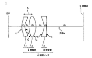
図1に本発明のファインダー光学系における一実施の形態の概略構成を示す。本実施形態のファインダー光学系1は、ビデオカメラ等の撮像装置において電子ビューファインダーに用いられる接眼レンズ4からなり、2.5インチから4インチ程度のやや大きめの画像表示装置を電子ビューファインダーに用いた場合に好適に用いられる。
FIG. 1 shows a schematic configuration of an embodiment of a finder optical system according to the present invention. The viewfinder
本実施形態におけるファインダー光学系1の接眼レンズ4は、アイポイントEPと画像面5との間の光路上に構成されており、第1のレンズL1、第2のレンズL2、第3のレンズL3より構成される。アイポイントEP側から順に、第1のレンズL1、第2のレンズL2、第3のレンズL3とする。第1のレンズL1及び第3のレンズL3は、プラスチック凹非球面レンズであり、第2のレンズL2は、プラスチック凸非球面レンズである。すなわち、本実施形態のファインダー光学系1の構成レンズは、全てプラスチックからなる非球面レンズである。
The
第1のレンズL1と第2のレンズL2は、一体で移動する移動群2を構成する。また、第3のレンズL3は、固定群3を構成する。そして、移動群2及び固定群3により、ファインダー光学系1の接眼レンズ4が構成される。
The first lens L 1 and second lens L 2 constitutes the moving
そして、第1のレンズL1におけるレンズのパワーをL1p、第2のレンズL2におけるレンズのパワーをL2p、第3のレンズL3におけるレンズのパワーをL3p、第1のレンズL1〜第3のレンズL3の3枚のレンズにおけるレンズのパワーの合計をLapとしたとき、以下の条件を満たす。
(1)−3.05<(L1p/Lap)<−0.89
(2)3.50<(L2p/Lap)<5.07
(3)−3.51<(L3p/Lap)<−1.76
(1)〜(3)の条件は、各収差を緩和する為の条件である。
The lens power in the first lens L 1 is L 1p , the lens power in the second lens L 2 is L 2p , the lens power in the third lens L 3 is L 3p , and the first lens L 1 When the total lens power of the three lenses of the third lens L 3 is L ap , the following condition is satisfied.
(1) −3.05 <(L 1p / L ap ) <− 0.89
(2) 3.50 <(L 2p / L ap ) <5.07
(3) −3.51 <(L 3p / L ap ) <− 1.76
The conditions (1) to (3) are conditions for relaxing each aberration.
(1)の条件について、3枚のレンズにおけるレンズのパワーの合計Lapに対する第1のレンズにおけるレンズのパワーLp1が−3.05倍より小さい場合は、周辺画質の悪化、特に倍率色収差の増大を招く。また、−0.89倍よりも大きいと、視度がプラス側における色収差及びコマ収差が増大する。 Regarding the condition (1), when the lens power L p1 of the first lens relative to the total lens power L ap of the three lenses is smaller than −3.05 times, the peripheral image quality deteriorates, in particular, the chromatic aberration of magnification. Incurs an increase. On the other hand, if it is larger than −0.89 times, chromatic aberration and coma aberration on the positive side of the diopter increase.
また、(2)の条件について、3枚のレンズにおけるレンズのパワーの合計Lapに対する第2のレンズにおけるレンズのパワーLp2が3.50倍より小さい場合は、視度がプラス側における色収差及びコマ収差が増大する。また、5.07倍よりも大きい場合は、画面周辺部での色収差及びコマ収差が増大する。 In the condition (2), when the lens power L p2 of the second lens with respect to the total lens power L ap of the three lenses is smaller than 3.50 times, the diopter is positive on the plus side. Coma increases. On the other hand, when it is larger than 5.07 times, chromatic aberration and coma aberration at the periphery of the screen increase.
また、(3)の条件について、3枚のレンズにおけるレンズのパワーの合計Lapに対する第3のレンズにおけるレンズのパワーLp3が−3.51倍より小さい場合は、視度がプラス側におけるコマ収差が増大する。また、−1.76倍よりも大きい場合は、視度がプラス側でのコマ収差が増大する。 In the condition (3), when the lens power L p3 of the third lens relative to the total lens power L ap of the three lenses is smaller than −3.51 times, the diopter is a coma on the plus side. Aberration increases. On the other hand, when it is larger than -1.76 times, coma aberration on the plus side of the diopter increases.
さらに、移動群2は、2枚のプラスチック非球面レンズL1,L2により、そのレンズL1,L2のパワーL1p、L2pの合計が正のパワーとなるように構成されている。
Further, the
また、第2のレンズL2における屈折率L2n及び、第1のレンズL1におけるアッベ数L1vは以下の条件を満たす。
(4)L2n>1.50
(5)20<L1v<37
The refractive index L 2n in the second lens L 2 and the Abbe number L 1v in the first lens L 1 satisfy the following conditions.
(4) L 2n > 1.50
(5) 20 <L 1v <37
(4)の条件について、屈折率L2nが1.50より低いと、レンズにパワーをもたせるときにレンズの曲率が急になりすぎるため、収差補正に不利となり、十分な軸外性能を得られない。
また、(5)の条件について、アッベ数が20よりも小さいと、適当な材料がなく、37よりも大きいと、十分な色収差補正ができなくなる。
Regarding the condition (4), if the refractive index L 2n is lower than 1.50, the lens curvature becomes too steep when the lens is given power, which is disadvantageous for aberration correction and sufficient off-axis performance can be obtained. Absent.
As for the condition (5), if the Abbe number is less than 20, there is no suitable material. If the Abbe number is greater than 37, sufficient chromatic aberration correction cannot be performed.
以上の条件により構成されるファインダー光学系1において、移動群2を光軸aに沿って矢印6方向に移動させることにより、視度調整がなされる。
本実施形態のファインダー光学系1においては、およそ、視度+1デオプター(+1D)から−3デオプター(−3D)まで対応することができる。図2A,Bに+1Dにおけるファインダー光学系の概略構成と、−3Dにおけるフィンダー光学系の概略構成を示す。図2A,Bに示すように、移動群2を移動させて、アイポイントEPに入射する入射光の角度を変化させることにより、視度が調整される。このような、ファインダー光学系1を介して画像面5をみることにより、アイポイントEPからは虚像を視認することができる。
In the finder
In the finder
また、本実施形態のファインダー光学系1では、アイポイントEP側からみて、手前にレンズのパワーが正である移動群2があり、その奥に固定群3となる凹レンズがあるため、光学系の全長、すなわち、画像面5から第1のレンズL1面までの長さを焦点距離よりも短くすることができる。従って、画像面5が大きくなった場合、焦点距離も長くなるが、本実施形態におけるファインダー光学系1においては、ファインダー光学系1の全長を短く構成することができる。
Further, in the finder
そして、移動群2を凹凸の2枚構成とし、2枚ともプラスチック非球面レンズとすることにより、収差量の少ない移動群2とすることができる。また、移動群2を2枚とも非球面プラスチックとすることで、レンズのパワーを強くしても収差補正能力を高くできるため、移動群2として、強い凸パワーを持ちながらも収差発生量の少ない光学系とすることができる。移動群2のレンズのパワーを強くすることができるため、少しの移動量で視度を大きく変化させることができ、視度調整範囲を広げることができる。
Then, the moving
さらに、固定群3もプラスチック非球面レンズとすることで、全体の光学系として良好な収差補正が可能となる。このため、広い視度調整範囲及び広い視野角に渡って良好な性能をもつファインダーにすることができ、均質な解像度を得ることができる。また、用いられる3枚のレンズが、全て非球面レンズであるため、大きめの画像面を用いるファインダー光学系においても、画面中心と周辺での視度が均一になるように設計することができ、視野内での視度均一化を図ることができる。
さらに、プラスチックレンズは軽量であり、ファインダー光学系のレンズ重量を軽減することができる。
Furthermore, by making the fixed group 3 a plastic aspheric lens, it becomes possible to correct aberrations as a whole optical system. For this reason, it can be set as the finder which has favorable performance over a wide diopter adjustment range and a wide viewing angle, and a uniform resolution can be obtained. In addition, since the three lenses used are all aspherical lenses, even in the finder optical system using a larger image surface, it can be designed so that the diopter at the center and the periphery of the screen is uniform. It is possible to make the diopter uniform within the field of view.
Furthermore, the plastic lens is lightweight, and the lens weight of the finder optical system can be reduced.
次に、上述したファインダー光学系の一実施の形態における実施例を示す。 Next, examples in one embodiment of the finder optical system described above will be shown.
図1に示したファンダー光学系1の実施例に係わる具体的な値を表1に示す。図1に示す接眼レンズ群4のレンズ面をアイポイントEP側から第1面〜第6面とする。

本実施例におけるレンズの第1面〜第6面の非球面形状は、以下の数1で表される。
表1におけるr1〜r6は各レンズ面の曲率半径、d1〜d5は各レンズ面間の距離、n1〜n3は各レンズの屈折率、v1〜v3は各レンズのアッベ数である。曲率半径、面間の距離、有効半径の単位はそれぞれmmである。K、A1、A2、A3、A4は前述した数1の非球面形状を表す係数である。また、本実施例において、第6面から画像表示装置までの距離d0は、103.1mmである。
R 1 ~r 6 in Table 1 is the radius of curvature of each lens surface, d 1 to d 5 is the distance between the lens surfaces, n 1 ~n 3 is the refractive index of each lens,
図3A、Bに、本実施例のファインダー光学系1において、視度を−3Dに調整したときと、視度を+1Dに調整したときの、球面収差(R,G,B)、非点収差、歪曲収差をそれぞれ示す。球面収差は、縦軸が光線高で、横軸が光軸方向の距離である。ここでは、代表的な波数による球面収差を図示する。また、非点収差は、縦軸が像高で横軸がピントずれ量である。破線はサジタル面で、実線はメリジオナル面である。歪曲収差は、縦軸が像高で、横軸が像の歪み量である。
3A and 3B, spherical aberration (R, G, B) and astigmatism when the diopter is adjusted to -3D and when the diopter is adjusted to + 1D in the finder
図3A,Bより、各収差はそれぞれの視度において実用十分な値であることがわかる。
すなわち、本実施例の値を用いたファインダー光学系では、移動群2の2枚のプラスチック非球面レンズL1,L2の組み合わせにおいて、レンズL1とレンズL2に対して互いに異なるプラスチック素材を選ぶことにより、実用十分な色収差補正がなされ、かつ、固定群もプラスチック非球面レンズとすることにより、良好な収差補正がなされた。また、視度が−3D及び+1Dにおいてどちらも諸収差が良好であることから、広い視度範囲及び広い視野角にわたり、高性能なファインダー光学系であることがわかる。
3A and 3B, each aberration is a practically sufficient value in each diopter.
That is, in the finder optical system using the values of the present embodiment, different plastic materials are used for the lens L 1 and the lens L 2 in the combination of the two plastic aspherical lenses L 1 and L 2 of the moving
次に、図4に本発明における撮像装置の一実施の形態に係る要部の概略構成を示す。
本実施形態における撮像装置は、電子ビューファンインダーに前述したファインダー光学系1が用いられる例である。
Next, FIG. 4 shows a schematic configuration of a main part according to an embodiment of the imaging apparatus of the present invention.
The imaging apparatus according to the present embodiment is an example in which the above-described finder
図4に示す撮像装置10には、撮影部11と、電子ビューファインダー12のみを示す。撮影部11は、例えば、CCD撮像素子、CMOS撮像素子等の撮像素子13と信号処理部14から構成され、電子ビューファインダー12は、画像表示装置17と、ファインダー光学系1から構成される。本実施形態で用いられる画像表示装置17は、2.5インチ〜4インチ程度の大型の表示装置である。
The
この撮像装置10では、撮影部11において、撮像素子13で得られた光学信号を信号処理部14により、電気的な画像信号15に変換する。そして画像信号15は、電子ビューファインダー12に送られ、ドライバ16を介して、例えば液晶ディスプレイパネル等の画像表示装置17に映し出される。この画像が映し出された画像表示装置17の画像面5を、ファインダー光学系1の接眼レンズ4を介してアイポイントEP側から見ることにより、拡大された画像を見ることができる。そして、電子ビューファインダー12のファインダー光学系1において、接眼レンズ4の移動群2を光軸aに沿って移動することにより、視度を調整することができる。すなわち、観察者の視力に合わせて視度を調整できる。
In the
本実施形態の撮像装置10では、電子ビューファインダー12において、ファインダー光学系1が、凹レンズ、及び凸レンズの2枚構成であり正のパワーを有する移動群2と、凹レンズの固定群3により構成される。このため、大型の画像表示装置17を用いた場合でも、レンズ系の全長を焦点距離よりも短くすることができる。また、非球面レンズを用いることにより移動群2のレンズのパワーを大きく設計することができるので、移動群2の少しの移動量で大きく視度を変化させることができ、そして、広い視度調整範囲を得ることができる。これにより、電子ビューファインダーを小さく構成することができる。
In the
さらに、本実施形態の撮像装置10によれば、プラスチック非球面レンズを用いることにより、画像表示装置17が大型化しても、視野内での視度の均一化を図ることができる。すなわち、画像表示装置17の画面中心と周辺の視度を均一化することができる。また、3枚ともプラスチックレンズで構成されるので、撮像装置10において、重量の軽減が図られる。また、3枚とも、非球面レンズにより構成されるため、収差補正が良好になされ、電子ビューファインダーにおいて、均質な解像度を得ることができる。
Furthermore, according to the
以上のように、本発明によれば、プラスチック凹非球面レンズ、プラスチック凸非球面レンズにより移動群を構成することにより、2枚のレンズによるレンズのパワーを強くしながらも、低収差なレンズ群とすることができる。また、この移動群とプラスチック凹非球面レンズにより固定群を組み合わせることにより、光学系をその焦点距離よりも短くすることができ、広い視度調整範囲及び広い視野角にわたって高性能なファインダー光学系を実現することができる。従って、本発明のファインダー光学系においては、撮像装置において、2.5インチ〜4インチ程度の大型の画像表示装置を用いた場合でも、視野内の視度均一化を図ることができる。 As described above, according to the present invention, the moving group is configured by the plastic concave aspheric lens and the plastic convex aspheric lens, so that the lens group with low aberration is obtained while increasing the lens power by the two lenses. It can be. In addition, by combining this moving group and a fixed group with a plastic concave aspherical lens, the optical system can be made shorter than its focal length, and a high-performance finder optical system over a wide diopter adjustment range and wide viewing angle. Can be realized. Therefore, in the finder optical system of the present invention, even when a large image display device of about 2.5 inches to 4 inches is used in the image pickup device, the diopter uniformity within the visual field can be achieved.
1・・ファインダー光学系、2・・移動群、3・・固定群、4・・接眼レンズ、5・・画像面、10・・撮像装置、11・・撮影部、12・・電子ビューファインダー、13・・撮像素子、14・・信号処理部、15・・画像信号、16・・ドライバ、17・・画像表示装置、EP・・アイポイント
1 .... finder
Claims (4)
プラスチック凸非球面レンズからなる第2のレンズと、
プラスチック凹非球面レンズからなる第3のレンズとがアイポイント側から画像面に向かって順に配され、
前記第1のレンズと前記第2のレンズにより構成される正のパワーを有する移動群が、
前記第3のレンズにより構成される固定群に対して、光軸に沿って一体に移動するように構成された
ことを特徴とするファインダー光学系。 A first lens comprising a plastic concave aspheric lens;
A second lens comprising a plastic convex aspheric lens;
A third lens composed of a plastic concave aspheric lens is arranged in order from the eye point side toward the image plane,
A moving group having a positive power constituted by the first lens and the second lens,
A viewfinder optical system configured to move integrally along the optical axis with respect to the fixed group constituted by the third lens.
(1)−3.05<(L1p/Lap)<−0.89
(2)3.50<(L2p/Lap)<5.07
(3)−3.51<(L3p/Lap)<−1.76
(4)L2n>1.50
(5)20<L1v<37
但し、
L1p:第1のレンズにおけるレンズのパワー
L2p:第2のレンズにおけるレンズのパワー
L3p:第3のレンズにおけるレンズのパワー
Lap:第1、第2及び第3のレンズにおけるレンズのパワーの合計
L2n:第2のレンズにおける屈折率
L1v:第1のレンズにおけるアッベ数
を満たす
ことを特徴とする請求項1記載のファインダー光学系。 The first, second and third lenses have the following conditions:
(1) −3.05 <(L 1p / L ap ) <− 0.89
(2) 3.50 <(L 2p / L ap ) <5.07
(3) −3.51 <(L 3p / L ap ) <− 1.76
(4) L 2n > 1.50
(5) 20 <L 1v <37
However,
L 1p : Lens power in the first lens L 2p : Lens power in the second lens L 3p : Lens power in the third lens L ap : Lens power in the first, second and third lenses The finder optical system according to claim 1, wherein: L 2n : Refractive index of the second lens L 1v : Abbe number of the first lens is satisfied.
前記撮像素子から得られた光学信号を画像信号に変換する信号処理部と、
前記画像信号による情報を表示する画像表示装置と、
前記画像表示装置に表示された画像を拡大して見ることのできるファインダー光学系とを備え、
前記ファインダー光学系は、プラスチック凹非球面レンズからなる第1のレンズと、
プラスチック凸非球面レンズからなる第2のレンズと、
プラスチック凹非球面レンズからなる第3のレンズとがアイポイント側から画像表示装置の画像面に向かって順に配され、
前記第1のレンズと前記第2のレンズにより構成される正のパワーを有する移動群が、
前記第3のレンズにより構成される固定群に対して、光軸に沿って一体に移動するように構成された
ことを特徴とする撮像装置。 An image sensor;
A signal processing unit that converts an optical signal obtained from the image sensor into an image signal;
An image display device for displaying information by the image signal;
A viewfinder optical system capable of enlarging and viewing the image displayed on the image display device,
The finder optical system includes a first lens made of a plastic concave aspheric lens,
A second lens comprising a plastic convex aspheric lens;
A third lens made of a plastic concave aspheric lens is sequentially arranged from the eye point side toward the image plane of the image display device,
A moving group having a positive power constituted by the first lens and the second lens,
An image pickup apparatus configured to move integrally along an optical axis with respect to a fixed group constituted by the third lens.
(1)−3.05<(L1p/Lap)<−0.89
(2)3.50<(L2p/Lap)<5.07
(3)−3.51<(L3p/Lap)<−1.76
(4)L2n>1.50
(5)20<L1v<37
但し、
L1p:第1のレンズにおけるレンズのパワー
L2p:第2のレンズにおけるレンズのパワー
L3p:第3のレンズにおけるレンズのパワー
Lap:第1、第2及び第3のレンズにおけるレンズのパワーの合計
L2n:第2のレンズにおける屈折率
L1v:第1のレンズにおけるアッベ数
を満たす
ことを特徴とする請求項3記載の撮像装置。 The first, second and third lenses in the imaging device have the following conditions:
(1) −3.05 <(L 1p / L ap ) <− 0.89
(2) 3.50 <(L 2p / L ap ) <5.07
(3) −3.51 <(L 3p / L ap ) <− 1.76
(4) L 2n > 1.50
(5) 20 <L 1v <37
However,
L 1p : Lens power in the first lens L 2p : Lens power in the second lens L 3p : Lens power in the third lens L ap : Lens power in the first, second and third lenses 4. The imaging device according to claim 3, wherein: L 2n : Refractive index of the second lens L 1v : Abbe number of the first lens is satisfied.
Priority Applications (1)
| Application Number | Priority Date | Filing Date | Title |
|---|---|---|---|
| JP2007162822A JP2009003105A (en) | 2007-06-20 | 2007-06-20 | Finder optical system and imaging apparatus |
Applications Claiming Priority (1)
| Application Number | Priority Date | Filing Date | Title |
|---|---|---|---|
| JP2007162822A JP2009003105A (en) | 2007-06-20 | 2007-06-20 | Finder optical system and imaging apparatus |
Publications (1)
| Publication Number | Publication Date |
|---|---|
| JP2009003105A true JP2009003105A (en) | 2009-01-08 |
Family
ID=40319574
Family Applications (1)
| Application Number | Title | Priority Date | Filing Date |
|---|---|---|---|
| JP2007162822A Pending JP2009003105A (en) | 2007-06-20 | 2007-06-20 | Finder optical system and imaging apparatus |
Country Status (1)
| Country | Link |
|---|---|
| JP (1) | JP2009003105A (en) |
Cited By (7)
| Publication number | Priority date | Publication date | Assignee | Title |
|---|---|---|---|---|
| CN102236151A (en) * | 2010-04-21 | 2011-11-09 | 大立光电股份有限公司 | Optical lens group for photographing |
| CN103105663A (en) * | 2011-11-11 | 2013-05-15 | 大立光电股份有限公司 | Imaging system |
| JP2014215471A (en) * | 2013-04-25 | 2014-11-17 | 京セラ株式会社 | Eyepiece optical system for finder, finder device, and image-capturing device using the same |
| CN104407432A (en) * | 2014-12-19 | 2015-03-11 | 中山联合光电科技有限公司 | High-low-temperature resistant high-resolution optical system capable of being used at daytime and night |
| JP2017003848A (en) * | 2015-06-12 | 2017-01-05 | キヤノン株式会社 | Ocular lens and observation device having the same |
| CN108592867A (en) * | 2018-05-21 | 2018-09-28 | 余姚舜宇智能光学技术有限公司 | Optical signal receives optics microscope group |
| CN110727101A (en) * | 2018-07-16 | 2020-01-24 | 玉晶光电股份有限公司 | Eyepiece optical system |
Citations (2)
| Publication number | Priority date | Publication date | Assignee | Title |
|---|---|---|---|---|
| JP2004109961A (en) * | 2002-07-26 | 2004-04-08 | Fuji Photo Optical Co Ltd | Viewfinder |
| JP2004172733A (en) * | 2002-11-18 | 2004-06-17 | Fuji Photo Optical Co Ltd | Viewfinder |
-
2007
- 2007-06-20 JP JP2007162822A patent/JP2009003105A/en active Pending
Patent Citations (2)
| Publication number | Priority date | Publication date | Assignee | Title |
|---|---|---|---|---|
| JP2004109961A (en) * | 2002-07-26 | 2004-04-08 | Fuji Photo Optical Co Ltd | Viewfinder |
| JP2004172733A (en) * | 2002-11-18 | 2004-06-17 | Fuji Photo Optical Co Ltd | Viewfinder |
Cited By (9)
| Publication number | Priority date | Publication date | Assignee | Title |
|---|---|---|---|---|
| CN102236151A (en) * | 2010-04-21 | 2011-11-09 | 大立光电股份有限公司 | Optical lens group for photographing |
| CN102236151B (en) * | 2010-04-21 | 2013-07-10 | 大立光电股份有限公司 | Optical lens group for photographing |
| CN103105663A (en) * | 2011-11-11 | 2013-05-15 | 大立光电股份有限公司 | Imaging system |
| JP2014215471A (en) * | 2013-04-25 | 2014-11-17 | 京セラ株式会社 | Eyepiece optical system for finder, finder device, and image-capturing device using the same |
| CN104407432A (en) * | 2014-12-19 | 2015-03-11 | 中山联合光电科技有限公司 | High-low-temperature resistant high-resolution optical system capable of being used at daytime and night |
| JP2017003848A (en) * | 2015-06-12 | 2017-01-05 | キヤノン株式会社 | Ocular lens and observation device having the same |
| CN108592867A (en) * | 2018-05-21 | 2018-09-28 | 余姚舜宇智能光学技术有限公司 | Optical signal receives optics microscope group |
| CN108592867B (en) * | 2018-05-21 | 2024-03-19 | 余姚舜宇智能光学技术有限公司 | Optical lens group for receiving optical signal |
| CN110727101A (en) * | 2018-07-16 | 2020-01-24 | 玉晶光电股份有限公司 | Eyepiece optical system |
Similar Documents
| Publication | Publication Date | Title |
|---|---|---|
| CN107884924B (en) | Eyepiece optical system and optical device | |
| US9454062B2 (en) | Observation optical system, viewfinder equipped with observation optical system and method for manufacturing observation optical system | |
| JP6003503B2 (en) | Eyepiece optical system, optical equipment | |
| JP6098838B2 (en) | Eyepiece optical system and imaging apparatus | |
| JP2016001209A (en) | Eyepiece and imaging apparatus | |
| JP2014074816A (en) | Ocular optical system, optical device, and observation method | |
| JP5587017B2 (en) | Viewfinder eyepiece | |
| US20160139361A1 (en) | Eyepiece optical system | |
| WO2014041773A1 (en) | Eyepiece and imaging device | |
| JP2018028632A (en) | Eyepiece and imaging apparatus | |
| JP2018010217A (en) | Eyepiece optical system, optical instrument, and eyepiece optical system manufacturing method | |
| JP2009003105A (en) | Finder optical system and imaging apparatus | |
| JPWO2017022670A1 (en) | Eyepiece optics and electronic viewfinder | |
| JP2018010218A (en) | Eyepiece optical system, optical instrument, and eyepiece optical system manufacturing method | |
| JP6003504B2 (en) | Eyepiece optical system, optical equipment | |
| JP2022136208A (en) | Observation device | |
| JP7191005B2 (en) | Eyepieces, viewing optics, and optics | |
| JP7229853B2 (en) | viewfinder and imaging device | |
| US9551864B2 (en) | Eyepiece lens and observation apparatus having the same | |
| JP2017044764A (en) | Viewfinder, and image pickup device | |
| JP4817758B2 (en) | Eyepiece optical system and viewfinder system using the same | |
| JP2000206409A (en) | Zoom lens and projection device having the same | |
| JP2020030421A (en) | Ocular lens and image capturing device | |
| JP2006106491A (en) | View finder | |
| JP7518177B2 (en) | Observation optical system and optical device |
Legal Events
| Date | Code | Title | Description |
|---|---|---|---|
| A621 | Written request for application examination |
Free format text: JAPANESE INTERMEDIATE CODE: A621 Effective date: 20100528 |
|
| A131 | Notification of reasons for refusal |
Free format text: JAPANESE INTERMEDIATE CODE: A131 Effective date: 20120417 |
|
| A02 | Decision of refusal |
Free format text: JAPANESE INTERMEDIATE CODE: A02 Effective date: 20120828 |