JP4236252B2 - Stage apparatus and exposure apparatus - Google Patents
Stage apparatus and exposure apparatus Download PDFInfo
- Publication number
- JP4236252B2 JP4236252B2 JP2003128183A JP2003128183A JP4236252B2 JP 4236252 B2 JP4236252 B2 JP 4236252B2 JP 2003128183 A JP2003128183 A JP 2003128183A JP 2003128183 A JP2003128183 A JP 2003128183A JP 4236252 B2 JP4236252 B2 JP 4236252B2
- Authority
- JP
- Japan
- Prior art keywords
- stage
- substrate
- slider
- fine movement
- coil
- Prior art date
- Legal status (The legal status is an assumption and is not a legal conclusion. Google has not performed a legal analysis and makes no representation as to the accuracy of the status listed.)
- Expired - Fee Related
Links
Images


Classifications
-
- G—PHYSICS
- G03—PHOTOGRAPHY; CINEMATOGRAPHY; ANALOGOUS TECHNIQUES USING WAVES OTHER THAN OPTICAL WAVES; ELECTROGRAPHY; HOLOGRAPHY
- G03F—PHOTOMECHANICAL PRODUCTION OF TEXTURED OR PATTERNED SURFACES, e.g. FOR PRINTING, FOR PROCESSING OF SEMICONDUCTOR DEVICES; MATERIALS THEREFOR; ORIGINALS THEREFOR; APPARATUS SPECIALLY ADAPTED THEREFOR
- G03F7/00—Photomechanical, e.g. photolithographic, production of textured or patterned surfaces, e.g. printing surfaces; Materials therefor, e.g. comprising photoresists; Apparatus specially adapted therefor
- G03F7/70—Microphotolithographic exposure; Apparatus therefor
- G03F7/708—Construction of apparatus, e.g. environment aspects, hygiene aspects or materials
- G03F7/70808—Construction details, e.g. housing, load-lock, seals or windows for passing light in or out of apparatus
- G03F7/70816—Bearings
-
- G—PHYSICS
- G03—PHOTOGRAPHY; CINEMATOGRAPHY; ANALOGOUS TECHNIQUES USING WAVES OTHER THAN OPTICAL WAVES; ELECTROGRAPHY; HOLOGRAPHY
- G03F—PHOTOMECHANICAL PRODUCTION OF TEXTURED OR PATTERNED SURFACES, e.g. FOR PRINTING, FOR PROCESSING OF SEMICONDUCTOR DEVICES; MATERIALS THEREFOR; ORIGINALS THEREFOR; APPARATUS SPECIALLY ADAPTED THEREFOR
- G03F7/00—Photomechanical, e.g. photolithographic, production of textured or patterned surfaces, e.g. printing surfaces; Materials therefor, e.g. comprising photoresists; Apparatus specially adapted therefor
- G03F7/70—Microphotolithographic exposure; Apparatus therefor
- G03F7/70691—Handling of masks or workpieces
- G03F7/70716—Stages
-
- G—PHYSICS
- G03—PHOTOGRAPHY; CINEMATOGRAPHY; ANALOGOUS TECHNIQUES USING WAVES OTHER THAN OPTICAL WAVES; ELECTROGRAPHY; HOLOGRAPHY
- G03F—PHOTOMECHANICAL PRODUCTION OF TEXTURED OR PATTERNED SURFACES, e.g. FOR PRINTING, FOR PROCESSING OF SEMICONDUCTOR DEVICES; MATERIALS THEREFOR; ORIGINALS THEREFOR; APPARATUS SPECIALLY ADAPTED THEREFOR
- G03F7/00—Photomechanical, e.g. photolithographic, production of textured or patterned surfaces, e.g. printing surfaces; Materials therefor, e.g. comprising photoresists; Apparatus specially adapted therefor
- G03F7/70—Microphotolithographic exposure; Apparatus therefor
- G03F7/70691—Handling of masks or workpieces
- G03F7/70775—Position control, e.g. interferometers or encoders for determining the stage position
-
- G—PHYSICS
- G03—PHOTOGRAPHY; CINEMATOGRAPHY; ANALOGOUS TECHNIQUES USING WAVES OTHER THAN OPTICAL WAVES; ELECTROGRAPHY; HOLOGRAPHY
- G03F—PHOTOMECHANICAL PRODUCTION OF TEXTURED OR PATTERNED SURFACES, e.g. FOR PRINTING, FOR PROCESSING OF SEMICONDUCTOR DEVICES; MATERIALS THEREFOR; ORIGINALS THEREFOR; APPARATUS SPECIALLY ADAPTED THEREFOR
- G03F7/00—Photomechanical, e.g. photolithographic, production of textured or patterned surfaces, e.g. printing surfaces; Materials therefor, e.g. comprising photoresists; Apparatus specially adapted therefor
- G03F7/70—Microphotolithographic exposure; Apparatus therefor
- G03F7/708—Construction of apparatus, e.g. environment aspects, hygiene aspects or materials
- G03F7/70858—Environment aspects, e.g. pressure of beam-path gas, temperature
- G03F7/70866—Environment aspects, e.g. pressure of beam-path gas, temperature of mask or workpiece
- G03F7/70875—Temperature, e.g. temperature control of masks or workpieces via control of stage temperature
Landscapes
- General Physics & Mathematics (AREA)
- Physics & Mathematics (AREA)
- Health & Medical Sciences (AREA)
- Epidemiology (AREA)
- Engineering & Computer Science (AREA)
- Environmental & Geological Engineering (AREA)
- Public Health (AREA)
- Toxicology (AREA)
- Atmospheric Sciences (AREA)
- Life Sciences & Earth Sciences (AREA)
- Exposure And Positioning Against Photoresist Photosensitive Materials (AREA)
- Exposure Of Semiconductors, Excluding Electron Or Ion Beam Exposure (AREA)
- Container, Conveyance, Adherence, Positioning, Of Wafer (AREA)
Description
【0001】
【発明の属する技術分野】
本発明は、半導体露光装置などの精密機械において半導体ウエハや露光原版等の基板を移動または位置決めするために用いられるステージ装置に関する。
【0002】
【従来の技術】
半導体製造工程において、原版であるレチクル基板のパターンを被露光基板であるシリコンウエハ上に投影して転写する投影露光装置では、レチクルパターンをウエハ上に投影露光する際、レチクルおよびシリコンウエハを投影露光系に対して順次移動させるためにステージ装置であるレチクルステージおよびウエハステージが用いられる。
【0003】
図5〜図9は、従来の投影露光装置の構成および動作を示す。図5は投影露光装置全体の概略構成図である。図5において、1は照明系ユニットで、露光光源(不図示)からの露光光を整形しレチクル(不図示)に対して照射する。2は露光パターンの原版であるレチクルを搭載するレチクルステージで、搭載したレチクルをウエハ8に対して所定の縮小露光倍率比で、スキャン動作させる。3は縮小投影レンズで、レチクルに形成された原版パターンをウエハ8に縮小投影する。4は露光装置本体、5はウエハステージで、露光装置本体4は、前記レチクルステージ2、投影レンズ3およびウエハステージ5を支持する。ウエハステージ5は、ウエハ8を順次の露光位置にステップ移動させるとともにレチクルのスキャン動作時、それと同期してウエハ8をスキャン動作させる。
【0004】
図6を参照して、ウエハステージ5は、ステージ定盤5Dおよびスライダ(移動体)5Cを備える。ウエハステージ5の上面(スライダ5Cの上面)には、照度センサ5Aおよびステージ基準マーク5Bが設けられている。照度センサ5Aは、露光光の照度を露光前にキャリブレーション計測し、露光量を補正するために用いられる。基準マーク5Bには、ステージアライメント計測用のターゲットが設けられている。なお、図5(1)において、スライダ5Cの上面のウエハチャックおよびウエハ部分は、縮小投影レンズ3、フォーカススコープ6の光線およびウエハ8の関係が分かるように、断面で表している。
【0005】
図7(2)の断面図に示されるように、スライダ5Cは、内部にスライダ5Cをステージ定盤5Dの上面(基準面)で面内駆動する平面モータ駆動コイル5Fが設けられている。この平面モータ駆動コイル5Fに対向して、ステージ定盤5Dに櫛歯鉄心ヨーク5Eが設けられ、平面モータ駆動コイル5Fにて励磁されたヨークと櫛歯鉄心ヨーク5Eとの相互作用によりスライダ5Cがステージ定盤5D上でXYの二次元方向に面内駆動される。
【0006】
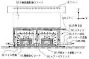
図8はスライダ5Cの詳細を示す断面図である。同図において、5Gはエアーベアリングである。エアーベアリング5Gは、スライダ5CをXY平面内に移動可能に支持する静圧軸受けで、エアーベアリング5Gへの供給エアー5Hを供給されることにより静圧力を発生する。5Nはスライダ5C上部に搭載された6軸微動駆動ステージで、ウエハ8をXYZ、θx、θy、θz方向に微動駆動し、ウエハ8を露光中に位置決めおよびフォーカスチルト駆動する。5Jは平面モータ駆動コイル5Fからのコイル発熱、5Kはエアー5Hのエアーベアリング5G供給後のエアー排気、5Qはコイル発熱による温度上昇を示す。なお、ここで、エアーとは、清浄化および乾燥化した空気の他、窒素ガスやヘリウムガスなどの不活性ガスまたはこれらの不活性ガスと空気の混合ガスをも含む概念で用いている。
【0007】
図5および図6に戻って、6はフォーカススコープで、縮小投影レンズ3の鏡筒から、ウエハ8のフォーカス計測を行う。6Aはアライメントスコープで、ウエハ上のアライメントマーク(不図示)およびウエハステージ上のアライメント用基準マーク5Bを計測し、ウエハ内アライメントおよびレチクルとウエハ間のアライメントを行う際の計測を行う顕微鏡である。7はウエハ搬送ロボットで、ウエハ8をウエハステージ5に供給する。8はレチクルに描かれたレチクルパターンを縮小露光系を通して投影転写するために、単結晶シリコン基板表面にレジストが塗られたウエハである。
【0008】
スライダ5Cには、スライダ5Cの位置(以下、ウエハステージの位置という)、すなわちウエハ8の位置を計測するため複数のレーザ干渉計(不図示)が搭載されている。9はX干渉計ミラーで、ウエハステージのX方向の位置をレーザ干渉計により計測するターゲットである。9AはX干渉計計測光である。10はY干渉計ミラーで同じくウエハステージ5のY方向の位置を計測するターゲットである。10AはY干渉計計測光である。
【0009】
【発明が解決しようとする課題】
ところで、本発明者らは、上記従来例においては、ステージ位置決め精度が位置計測系およびステージ駆動系の構成から予測および期待されるレベルに達しておらず、さらなる精度向上が期待されることを見出した。本発明者らは、この従来例における制御精度悪化の原因を検討した結果、以下の知見を得た。
【0010】
すなわち、図5〜図8の構成で、図9に示すように、スライダ5Cを移動制御する際に、駆動コイル5Fに駆動電流が印加されることにより、スライダ5Cの外周部温度が上昇する。スライダ5Cの温度が上昇することにより、上記エアーベアリング5Gのエアー5H供給系を通してエアー温度が上昇し、結果として排気エアー5Kの温度が上昇し、スライダ5C周辺部の空間温度が上昇する。結果として、空間空気のゆらぎ現象が発生し、X干渉計計測光9AおよびY干渉計計測光10Aに対して計測誤差要因として働き、計測誤差を生む。
【0011】
また、スライダ5Cの温度が上昇することにより、スライダ5Cの上部に搭載された6軸微動駆動ステージ5Nに伝熱し、6軸微動駆動ステージ5Nに温度上昇5Lが発生し、6軸微動駆動ステージ5Nおよびウエハ8の支持手段に対して熱歪を発生させる原因になっていた。
【0012】
結果として、スライダ5Cを干渉計計測値により目標位置に位置決めする際に、目標値誤差発生となり、ステージ装置の制御精度が悪化する。また、ウエハ平坦度の悪化により、露光フォーカス精度の悪化を招き、トータルで露光装置の性能を劣化させていた。
【0013】
本発明では、上記従来例の構成で問題になっていた以下の問題点に着目する。すなわち、(1)平面モータ駆動コイル発熱による、スライダ内部に構成されているスライダエアーベアリングの供給エアーの温度上昇、および(2)平面モータスライダ上に搭載される6軸微動駆動ステージへの平面モータ駆動コイル発熱からの伝熱による6軸微動駆動ステージおよびウエハ支持手段の熱歪の発生である。
本発明では、スライダエアーベアリングの供給エアーの温度上昇による干渉計計測空間の揺らぎの発生、ならびに6軸微動駆動ステージおよびウエハ支持手段の熱歪の発生を防ぎ、もって、ステージ位置決め精度の向上を図ることを課題とする。
【0014】
【課題を解決するための手段】
上記の課題を達成するための本発明のステージ装置は、基準面を有する定盤と、基板を搭載して移動する移動体と、前記移動体に設けられ、該移動体を前記基準面上で移動可能に支持する静圧軸受け手段と、前記移動体に設けられたコイルを含み、該移動体を基準面上で駆動する駆動手段とを有するステージ装置において、前記基板を搭載する搭載部と前記コイルとの間に、前記コイルを温調する温調手段を備え、該温調手段によって前記静圧軸受け手段へ供給される気体が温調されることを特徴とする。
【0015】
【作用】
本発明によれば、静圧軸受け手段へ供給される気体を移動体内で温調する温調手段を設けるとともに、その温調手段を基板保持手段と電磁子駆動手段との中間に配置している。これにより、電磁子駆動手段の発熱による静圧軸受け手段へ供給され排気される気体の温度上昇を防いで干渉計計測空間の揺らぎを防止し、かつ、電磁子駆動手段の発熱の基板保持手段への伝熱を遮断して基板保持手段および基板の熱歪を防止することができ、ステージ位置決め精度が向上する。
【0016】
【発明の実施の形態】
本発明の好ましい実施の形態において、本発明は、スキャナもしくは走査露光装置と呼ばれるステップアンドスキャン型の投影露光装置またはステッパと呼ばれるステップアンドリピート型の投影露光装置のウエハステージまたはウエハステージとレチクルステージに適用される。その場合、前記基板は、原版または被露光基板である。
【0017】
すなわち、本発明の好ましい実施の形態に係る露光装置は、原版面に描かれたパターンを投影光学系を介して被露光基板に投影し、該投影光学系に対し原版と基板の両方、もしくは基板のみをステージ装置により相対的に移動させることにより、原版のパターンを基板に繰り返し露光する露光装置であって、基板ステージあるいは原版ステージ可動部に、XY平面内を移動可能に駆動する電磁子駆動手段および該可動部をXY面内方向に移動可能に支持する静圧軸受け手段が設けられ、該電磁子駆動手段に隣接した位置に冷却温調手段が設けられ、該冷却温調手段と該静圧軸受け手段への静圧気体供給手段が隣接して設けられていることを特徴とする露光装置である。この露光装置においては、前記電磁子駆動手段に隣接した位置に設けられた前記冷却温調手段の内部に前記静圧気体供給手段を設けることができる。
【0018】
本発明の好ましい他の実施の形態に係る露光装置は、原版面に描かれたパターンを投影光学系を介して被露光基板に投影し、該投影光学系に対し原版と基板の両方、もしくは基板のみをステージ装置により相対的に移動させることにより、原版のパターンを基板に繰り返し露光する露光装置であって、基板ステージあるいは原版ステージ可動部に、XY平面内を移動可能に駆動する電磁子駆動手段、および該XY平面内移動可能な可動スライダ上に基板あるいは原版を少なくとも1軸方向に駆動する微動駆動手段を設けられ、かつ該可動スライダと該微動駆動手段間あるいは可動スライダに冷却温調手段が設けられたことを特徴とする露光装置である。微動駆動手段としては、基板あるいは原版を6軸駆動するものを用いることができる。この露光装置において、前記冷却温調手段は、前記可動スライダ内の外周面あるいはスライダ部材内部に設けることが好ましい。
【0019】
【実施例】
以下に本発明の実施例を説明する。
[実施例1]
図1は、本発明の第1の実施例に係るスライダの構成を示す。このスライダは、図5〜図9を用い従来例として説明した露光装置に適用されたもので、図8に示すスライダ部分に冷却手段5Lを付加したものである。したがって、他の構成は同一であるので、図1において、図8と共通する部分には同一の符号を付して説明を省略する。
【0020】
図1の構成において、5Lは冷却手段で、冷媒5Mを流すことによりコイル発熱5Jを回収する。冷媒5Mとしては、例えば水、純水、不活性フッ素等を用いることができる。一方、スライダ5Cを移動制御する際に、駆動コイル5Fに駆動電流が印加されることにより、スライダ5Cの外周部温度が上昇する。スライダ5Cの温度が上昇することにより、上記エアーベアリング5Gのエアー5H供給系を通してエアー温度が上昇する。これを防ぐために、平面モータ駆動コイル5Fに隣接して、冷却手段5Lを設けることにより、冷媒5Mを流しコイル発熱5Jを回収する。結果として排気エアー5Kの温度の上昇を低減し、スライダ5C周辺部の空間温度の上昇を防ぎ、空間温調の乱れを防ぐことができる。空間温調の乱れ、すなわち空間空気のゆらぎ現象を防ぐことができる結果、図5〜7に示すX干渉計計測光9AおよびY干渉計計測光10Aに対して計測誤差要因を無くし、計測精度を向上させることができる。
【0021】
また、スライダ5Cの温度上昇を、冷却手段5Lにより低減し、かつ、スライダ5Cの上部に搭載された6軸微動駆動ステージ5Nへの伝熱を遮断することにより、6軸微動駆動ステージ5Nおよびウエハ8の支持手段に対する熱歪の発生を抑制することができる。結果として、スライダ5Cを干渉計計測値により、目標位置に位置決めする際に、目標値誤差発生を無くすることができ、ステージ装置の制御精度が向上する。また、ウエハ平坦度の悪化を防ぐことができ、露光フォーカス精度の向上を実現し、トータルで露光装置の性能を向上させることができる。
【0022】
[実施例2]
第2の実施例を図2に示す。第1の実施例では、冷却手段5Lを、平面モータ駆動コイル5Fに隣接させて設けていたが、6軸微動駆動ステージ5Nとスライダ5Cとの間の6軸微動駆動ステージ5Nのベースである微動ベース5Pに設けることにより、平面モータ駆動コイル5Fの発熱が少ない場合は、6軸微動駆動ステージ5Nへの発熱を遮断するのみの構成も可能である。結果として、従来例より高精度の計測と駆動を行うこと、および6軸微動駆動ステージ5Nの制御精度を向上させることが可能になる。
【0023】
[実施例3]
第3の実施例を図3に示す。第1の実施例では、冷却手段5Lを、平面モータ駆動コイル5Fの上部面に隣接させているが、平面モータ駆動コイル5Fの発熱が大きく、より厳しい条件での温調が必要な場合、図3に示すように平面モータ駆動コイル5Fの周囲を覆うように冷却手段5Lを設け、冷却手段5Lの外周部に隣接してエアー5Hの供給配管を設ける。これにより、平面モータ駆動コイル5Fのコイル発熱5Jの影響を受けずに、エアーベアリング5Gへのエアー5Hの供給が可能になる。
【0024】
[実施例4]
第4の実施例を図4に示す。図4に示すように、平面モータ駆動コイル5Fの周囲を覆うように、スライダ5Cが被さる構造の場合、スライダ5C自身の内部あるいは表面に、冷却手段5Lを設けることにより、スライダ5C全体を冷却温調することが可能になる。
【0025】
上記の実施例によれば、平面モータステージで、スライダに設けられた駆動コイルの外周部に冷却温調手段を隣接して設け、スライダのXY平面内移動支持手段である、エアーベアリングへの供給エアー配管経路を、冷却温調手段に隣接あるいは内部を通して配置することにより、スライダの熱源の影響を受けずにエアーの供給が可能になり、スライダのエアーベアリング部から排気されるエアーによる、干渉計計測空間のゆらぎの発生を抑えることができ、ステージ位置決め精度が向上する。また、平面モータスライダ上に搭載される、6軸微動駆動ステージへの平面モータ駆動コイル発熱からの伝熱を遮断するために、平面モータスライダと6軸微動駆動ステージ5Nとの間に冷却温調手段を設けることにより、6軸微動駆動ステージおよびウエハ支持手段への熱歪の発生を防ぐことができる。
【0026】
【発明の適用範囲】
本発明は、上記実施例の限定されることなく適宜変形して実施することができる。例えば、温調エアーは、窒素ガスやヘリウムガスなどの不活性ガスまたはこれらの不活性ガスと空気との混合気体であっても良い。また、上述においては、主に、本発明をいわゆるスキャナに適用した例について説明したが、本発明は、いわゆるステッパ等他の方式の露光装置や、露光装置以外の半導体製造装置や走査型電子顕微鏡などの精密機械にも適用可能である。
【0027】
【実施態様】
本発明の実施態様の例を以下のように列挙する。
[実施態様1] 基準面を有する定盤と、基板を搭載して該基準面上で移動する移動体とを有し、前記移動体に、該移動体を前記基準面上で移動可能に支持する静圧軸受け手段と、該移動体を基準面内で駆動する電磁子駆動手段とを有する駆動するステージ装置において、
前記移動体の前記基板を保持する基板保持手段と前記電磁子駆動手段との間に、前記静圧軸受け手段へ供給される気体を温調する温調手段を設けたことを特徴とするステージ装置。
[実施態様2] 前記温調手段が前記電磁子駆動手段に隣接して設けられていることを特徴とする実施態様1に記載のステージ装置。
[実施態様3] 前記静圧気体供給手段が前記温調手段の内部に設けられていることを特徴とする実施態様1または2に記載のステージ装置。
[実施態様4] 前記移動体に、前記被駆動基板を少なくとも1軸方向に駆動する微動駆動手段を有し、該移動体と該微動駆動手段間あるいは該移動体に前記温調手段が設けられていることを特徴とする実施態様1〜3のいずれか1つに記載のステージ装置。
[実施態様5] 前記微動駆動手段は前記被駆動基板を6軸駆動するものであることを特徴とする実施態様4に記載のステージ装置。
[実施態様6] 前記温調手段は、前記移動体内の外周面近傍あるいは該移動体を構成する部材の内部に設けられていることを特徴とする実施態様1〜5のいずれか1つに記載のステージ装置。
[実施態様7] 原版面に描かれたパターンを投影光学系を介して被露光基板に投影し、該投影光学系に対し原版と被露光基板の両方、もしくは被露光基板のみをステージ装置により相対的に移動させることにより、原版のパターンを基板に繰り返し露光する露光装置であって、
前記原版または被露光基板を前記投影光学系に対し相対的に移動させるためのステージ装置の少なくとも1つが実施態様1〜6のいずれか1つに記載のステージ装置であることを特徴とする露光装置。
【0028】
【発明の効果】
本発明によれば、静圧軸受け手段へ供給される気体を移動体内で温調する温調手段を移動体内に設けるとともに、その温調手段を移動体内の基板保持手段と電磁子駆動手段との中間に配置している。これにより、電磁子駆動手段の発熱による静圧軸受け手段へ供給され排気される気体の温度上昇を防いで干渉計計測空間の揺らぎを防止し、かつ、電磁子駆動手段の発熱の基板保持手段への伝熱を遮断して基板保持手段および被駆動基板の熱歪を防止することができ、ステージ位置決め精度が向上する。
【図面の簡単な説明】
【図1】 本発明の第1の実施例に係る平面モータステージの説明図である。
【図2】 第2の実施例に係る平面モータステージ説明図である。
【図3】 第3の実施例に係る平面モータステージ説明図である。
【図4】 第4の実施例に係る平面モータステージ説明図である。
【図5】 従来例に係る露光装置全体の概略構成を示す図である。
【図6】 図5の従来例における平面モータステージの構成を示す斜視図である。
【図7】 図5の従来例における平面モータステージの動作説明図である。
【図8】 図7の平面モータステージのより詳細な構成を示す断面図である。
【図9】 図8の平面モータステージの動作範囲の説明図である。
【符号の説明】
1:照明系ユニット、2:レチクルステージ、3:縮小投影レンズ、4:露光装置本体、5:ウエハステージ、5A:照度センサ、5B:基準マーク、5C:スライダ、5D:ステージ定盤、5E:櫛歯鉄心ヨーク、5F:駆動コイル、5G:エアーベアリング、5H:エアー、5J:コイル発熱、5K:エアー排気、5L:冷却手段、5M:冷媒、5N:6軸微動駆動ステージ、5P:微動ベース、5Q:温度上昇、6:フォーカススコープ、6A:アライメントスコープ、7:ウエハ搬送ロボット、8:ウエハ、9:X干渉計ミラー、9A:X干渉計計測光、10:Y干渉計ミラー、10A:Y干渉計計測光。[0001]
BACKGROUND OF THE INVENTION
The present invention relates to a stage apparatus used for moving or positioning a substrate such as a semiconductor wafer or an exposure original plate in a precision machine such as a semiconductor exposure apparatus.
[0002]
[Prior art]
In a semiconductor manufacturing process, a projection exposure apparatus that projects and transfers a pattern of a reticle substrate, which is an original plate, onto a silicon wafer, which is an exposed substrate, projects and exposes the reticle and silicon wafer when projecting and exposing the reticle pattern onto the wafer. A reticle stage and a wafer stage, which are stage devices, are used to sequentially move the system.
[0003]
5 to 9 show the configuration and operation of a conventional projection exposure apparatus. FIG. 5 is a schematic block diagram of the entire projection exposure apparatus. In FIG. 5,
[0004]
Referring to FIG. 6, wafer stage 5 includes a stage surface plate 5D and a slider (moving body) 5C. An illuminance sensor 5A and a stage reference mark 5B are provided on the upper surface of the wafer stage 5 (the upper surface of the slider 5C). The illuminance sensor 5A is used to calibrate and measure the illuminance of exposure light before exposure and to correct the exposure amount. The reference mark 5B is provided with a target for stage alignment measurement. In FIG. 5A, the wafer chuck and the wafer portion on the upper surface of the slider 5C are shown in cross section so that the relationship between the reduction projection lens 3, the light beam of the focus scope 6 and the wafer 8 can be understood.
[0005]
As shown in the sectional view of FIG. 7B, the slider 5C is provided with a planar motor drive coil 5F that drives the slider 5C in-plane with the upper surface (reference surface) of the stage surface plate 5D. Opposite to the planar motor driving coil 5F, a comb iron yoke 5E is provided on the stage surface plate 5D, and the slider 5C is caused by the interaction between the yoke excited by the planar motor driving coil 5F and the comb iron yoke 5E. In-plane driving is performed in the XY two-dimensional direction on the stage surface plate 5D.
[0006]
FIG. 8 is a cross-sectional view showing details of the slider 5C. In the figure, 5G is an air bearing. The air bearing 5G is a static pressure bearing that supports the slider 5C so as to be movable in the XY plane, and generates a static pressure when the supply air 5H is supplied to the air bearing 5G. Reference numeral 5N denotes a 6-axis fine movement driving stage mounted on the upper part of the slider 5C. The wafer 8 is finely driven in the XYZ, θx, θy, and θz directions, and the wafer 8 is positioned and focused and tilted during exposure. Reference numeral 5J denotes coil heat generation from the planar motor drive coil 5F, 5K denotes air exhaust after supplying the air bearing 5G of air 5H, and 5Q denotes temperature rise due to coil heat generation. Here, the air is used in a concept including not only purified and dried air but also an inert gas such as nitrogen gas or helium gas or a mixed gas of these inert gas and air.
[0007]
Returning to FIGS. 5 and 6, reference numeral 6 denotes a focus scope, which performs focus measurement of the wafer 8 from the lens barrel of the reduction projection lens 3. Reference numeral 6A denotes an alignment scope, which is a microscope that measures an alignment mark (not shown) on the wafer and an alignment reference mark 5B on the wafer stage, and performs measurement when performing in-wafer alignment and alignment between the reticle and the wafer. A wafer transfer robot 7 supplies the wafer 8 to the wafer stage 5. Reference numeral 8 denotes a wafer having a single crystal silicon substrate surface coated with a resist in order to project and transfer the reticle pattern drawn on the reticle through a reduction exposure system.
[0008]
A plurality of laser interferometers (not shown) are mounted on the slider 5C in order to measure the position of the slider 5C (hereinafter referred to as the position of the wafer stage), that is, the position of the wafer 8. Reference numeral 9 denotes an X interferometer mirror, which is a target for measuring the position of the wafer stage in the X direction with a laser interferometer. 9A is X interferometer measurement light. Reference numeral 10 denotes a Y interferometer mirror, which is also a target for measuring the position of the wafer stage 5 in the Y direction. Reference numeral 10A denotes Y interferometer measurement light.
[0009]
[Problems to be solved by the invention]
By the way, the present inventors have found that in the above-described conventional example, the stage positioning accuracy does not reach the level predicted and expected from the configuration of the position measurement system and the stage drive system, and further improvement in accuracy is expected. It was. As a result of examining the cause of the deterioration of control accuracy in this conventional example, the present inventors have obtained the following knowledge.
[0010]
That is, in the configuration of FIGS. 5 to 8, when the slider 5C is moved and controlled as shown in FIG. 9, the drive current is applied to the drive coil 5F, so that the outer peripheral temperature of the slider 5C rises. As the temperature of the slider 5C rises, the air temperature rises through the air 5H supply system of the air bearing 5G. As a result, the temperature of the exhaust air 5K rises, and the space temperature around the slider 5C rises. As a result, a fluctuation phenomenon of the space air occurs, which acts as a measurement error factor for the X interferometer measurement light 9A and the Y interferometer measurement light 10A, thereby generating a measurement error.
[0011]
Further, when the temperature of the slider 5C rises, heat is transferred to the 6-axis fine movement drive stage 5N mounted on the upper portion of the slider 5C, and a temperature rise 5L is generated in the 6-axis fine movement drive stage 5N. In addition, thermal strain is generated in the support means for the wafer 8.
[0012]
As a result, when the slider 5C is positioned at the target position by the interferometer measurement value, a target value error occurs, and the control accuracy of the stage apparatus deteriorates. Further, the deterioration of wafer flatness causes the exposure focus accuracy to deteriorate, and the performance of the exposure apparatus is deteriorated in total.
[0013]
In the present invention, attention is paid to the following problems that have been a problem in the configuration of the conventional example. That is, (1) the temperature rise of the supply air of the slider air bearing formed inside the slider due to the heat generated by the planar motor drive coil, and (2) the planar motor to the 6-axis fine drive stage mounted on the planar motor slider This is the generation of thermal strain in the 6-axis fine movement drive stage and the wafer support means due to heat transfer from the drive coil heat generation.
In the present invention, the fluctuation of the interferometer measurement space due to the temperature rise of the supply air of the slider air bearing and the occurrence of thermal distortion of the 6-axis fine movement drive stage and the wafer support means are prevented, thereby improving the stage positioning accuracy. This is the issue.
[0014]
[Means for Solving the Problems]
In order to achieve the above object, a stage apparatus of the present invention includes a surface plate having a reference surface, a moving body that moves by mounting a substrate, the moving body, and the moving body on the reference surface. In a stage apparatus having a hydrostatic bearing means for movably supporting and a driving means for driving the movable body on a reference plane, including a coil provided on the movable body, a mounting portion for mounting the substrate, and between the coil comprises a temperature control means for temperature control of said coil, characterized in that the gas supplied to the hydrostatic bearing means is temperature control by the temperature adjusting unit.
[0015]
[Action]
According to the present invention, the temperature adjusting means for adjusting the temperature of the gas supplied to the static pressure bearing means in the moving body is provided, and the temperature adjusting means is disposed between the substrate holding means and the electromagnetic driving means. . As a result, the temperature of the gas supplied to and exhausted from the static pressure bearing means due to the heat generated by the electromagnetic driving means is prevented to prevent the interferometer measurement space from fluctuating, and the generated heat of the electromagnetic driving means can be transferred to the substrate holding means. The heat transfer between the substrate holding means and the substrate can be prevented, and the stage positioning accuracy is improved.
[0016]
DETAILED DESCRIPTION OF THE INVENTION
In a preferred embodiment of the present invention, the present invention relates to a wafer stage or a wafer stage and a reticle stage of a step-and-scan type projection exposure apparatus called a scanner or a scanning exposure apparatus or a step-and-repeat type projection exposure apparatus called a stepper. Applied. In this case, the substrate is an original plate or a substrate to be exposed.
[0017]
That is, an exposure apparatus according to a preferred embodiment of the present invention projects a pattern drawn on an original surface onto a substrate to be exposed via a projection optical system, and both the original and substrate, or the substrate with respect to the projection optical system. Is an exposure device that repeatedly exposes a pattern of an original on a substrate by relatively moving only the substrate by means of a stage device, and an electromagnetic driving means for driving the substrate stage or the original stage movable part to be movable in the XY plane And a static pressure bearing means for movably supporting the movable part in the XY plane direction, a cooling temperature adjusting means is provided at a position adjacent to the electromagnetic driving means, and the cooling temperature adjusting means and the static pressure are provided. An exposure apparatus characterized in that a static pressure gas supply means is provided adjacent to the bearing means. In this exposure apparatus, the static pressure gas supply means can be provided inside the cooling temperature adjusting means provided at a position adjacent to the electromagnetic driving means.
[0018]
An exposure apparatus according to another preferred embodiment of the present invention projects a pattern drawn on an original surface onto a substrate to be exposed through a projection optical system, and both the original and substrate, or the substrate with respect to the projection optical system. Is an exposure device that repeatedly exposes a pattern of an original on a substrate by relatively moving only the substrate by means of a stage device, and an electromagnetic driving means for driving the substrate stage or the original stage movable part to be movable in the XY plane And a fine movement driving means for driving the substrate or the original plate in at least one axial direction on a movable slider movable in the XY plane, and a cooling temperature adjusting means is provided between the movable slider and the fine movement driving means or on the movable slider. An exposure apparatus is provided. As the fine movement driving means, one that drives the substrate or the original plate 6 axes can be used. In this exposure apparatus, the cooling temperature adjusting means is preferably provided on the outer peripheral surface of the movable slider or the slider member.
[0019]
【Example】
Examples of the present invention will be described below.
[Example 1]
FIG. 1 shows the configuration of a slider according to a first embodiment of the present invention. This slider is applied to the exposure apparatus described as a conventional example with reference to FIGS. 5 to 9, and a cooling means 5L is added to the slider portion shown in FIG. Therefore, since the other configuration is the same, in FIG. 1, the same reference numerals are given to portions common to FIG. 8, and description thereof is omitted.
[0020]
In the configuration of FIG. 1, 5L is a cooling means, and collects the coil heat generation 5J by flowing a refrigerant 5M. As the refrigerant 5M, for example, water, pure water, inert fluorine, or the like can be used. On the other hand, when the movement of the slider 5C is controlled, a drive current is applied to the drive coil 5F, so that the outer peripheral temperature of the slider 5C increases. As the temperature of the slider 5C rises, the air temperature rises through the air 5H supply system of the air bearing 5G. In order to prevent this, the cooling means 5L is provided adjacent to the planar motor drive coil 5F, thereby flowing the refrigerant 5M and collecting the coil heat generation 5J. As a result, a rise in the temperature of the exhaust air 5K can be reduced, a rise in the space temperature around the slider 5C can be prevented, and a disturbance in the space temperature can be prevented. As a result of preventing the fluctuation of the spatial temperature, that is, the fluctuation phenomenon of the spatial air, the measurement error factor is eliminated with respect to the X interferometer measurement light 9A and the Y interferometer measurement light 10A shown in FIGS. Can be improved.
[0021]
Further, the temperature rise of the slider 5C is reduced by the cooling means 5L, and the heat transfer to the 6-axis fine drive stage 5N mounted on the upper part of the slider 5C is cut off, so that the 6-axis fine drive stage 5N and the wafer are removed. The occurrence of thermal strain on the support means 8 can be suppressed. As a result, when the slider 5C is positioned at the target position by the interferometer measurement value, the target value error can be eliminated, and the control accuracy of the stage apparatus is improved. In addition, the wafer flatness can be prevented from being deteriorated, the exposure focus accuracy can be improved, and the performance of the exposure apparatus can be improved in total.
[0022]
[Example 2]
A second embodiment is shown in FIG. In the first embodiment, the cooling means 5L is provided adjacent to the planar motor drive coil 5F, but the fine movement that is the base of the 6-axis fine movement drive stage 5N between the 6-axis fine movement drive stage 5N and the slider 5C. By providing the base 5P, when the flat motor drive coil 5F generates a small amount of heat, it is possible to simply block the heat generation to the 6-axis fine movement drive stage 5N. As a result, it is possible to perform measurement and driving with higher accuracy than in the conventional example and to improve the control accuracy of the 6-axis fine movement driving stage 5N.
[0023]
[Example 3]
A third embodiment is shown in FIG. In the first embodiment, the cooling means 5L is adjacent to the upper surface of the planar motor driving coil 5F. However, when the planar motor driving coil 5F generates a large amount of heat and temperature control under more severe conditions is required, FIG. As shown in FIG. 3, the cooling means 5L is provided so as to cover the periphery of the planar motor drive coil 5F, and an air 5H supply pipe is provided adjacent to the outer periphery of the cooling means 5L. As a result, the air 5H can be supplied to the air bearing 5G without being affected by the coil heat generation 5J of the planar motor drive coil 5F.
[0024]
[Example 4]
A fourth embodiment is shown in FIG. As shown in FIG. 4, in the case of a structure in which the slider 5C covers the flat motor drive coil 5F so as to cover the periphery, the cooling means 5L is provided inside or on the surface of the slider 5C to thereby cool the entire slider 5C. Can be adjusted.
[0025]
According to the above embodiment, in the planar motor stage, the cooling temperature adjusting means is provided adjacent to the outer peripheral portion of the drive coil provided on the slider, and the supply to the air bearing which is the XY in-plane movement support means of the slider is provided. By arranging the air piping path adjacent to or through the cooling temperature control means, air can be supplied without being affected by the heat source of the slider, and the interferometer is caused by the air exhausted from the air bearing section of the slider. Generation of fluctuations in the measurement space can be suppressed, and the stage positioning accuracy is improved. Further, in order to cut off heat transfer from the heat generated by the planar motor drive coil to the 6-axis fine drive stage mounted on the flat motor slider, the cooling temperature adjustment is performed between the planar motor slider and the 6-axis fine drive stage 5N. By providing the means, it is possible to prevent occurrence of thermal strain on the six-axis fine movement driving stage and the wafer support means.
[0026]
[Scope of the invention]
The present invention can be implemented with appropriate modifications without being limited to the above embodiments. For example, the temperature-controlled air may be an inert gas such as nitrogen gas or helium gas, or a mixed gas of these inert gas and air. In the above description, an example in which the present invention is applied to a so-called scanner has been mainly described. However, the present invention can be applied to other types of exposure apparatuses such as so-called steppers, semiconductor manufacturing apparatuses other than exposure apparatuses, and scanning electron microscopes. It is also applicable to precision machines such as
[0027]
Embodiment
Examples of embodiments of the present invention are listed as follows.
[Embodiment 1] A surface plate having a reference surface and a moving body mounted on the substrate and moving on the reference surface are supported by the moving body so as to be movable on the reference surface. In the stage apparatus to be driven having the static pressure bearing means to be driven and the electromagnetic driving means for driving the movable body in the reference plane,
A stage apparatus characterized in that a temperature adjusting means for adjusting the temperature of the gas supplied to the static pressure bearing means is provided between the substrate holding means for holding the substrate of the movable body and the electromagnetic driving means. .
[Embodiment 2] The stage apparatus according to
[Embodiment 3] The stage apparatus according to
[Embodiment 4] The movable body has fine movement driving means for driving the driven substrate in at least one axial direction, and the temperature adjusting means is provided between the movable body and the fine movement driving means or on the movable body. The stage apparatus as described in any one of Embodiments 1-3 characterized by the above-mentioned.
[Embodiment 5] The stage apparatus according to Embodiment 4, wherein the fine movement driving means drives the driven substrate in six axes.
[Embodiment 6] In any one of
[Embodiment 7] A pattern drawn on an original surface is projected onto an exposed substrate via a projection optical system, and both the original plate and the exposed substrate or only the exposed substrate are relative to the projection optical system by a stage device. Is an exposure apparatus that repeatedly exposes a pattern of an original on a substrate by moving it,
An exposure apparatus, wherein at least one stage apparatus for moving the original plate or the substrate to be exposed relative to the projection optical system is the stage apparatus according to any one of
[0028]
【The invention's effect】
According to the present invention, the temperature adjusting means for adjusting the temperature of the gas supplied to the static pressure bearing means in the moving body is provided in the moving body, and the temperature adjusting means is provided between the substrate holding means and the electromagnetic driving means in the moving body. Arranged in the middle. As a result, the temperature of the gas supplied to and exhausted from the static pressure bearing means due to the heat generated by the electromagnetic driving means is prevented to prevent the interferometer measurement space from fluctuating, and the generated heat of the electromagnetic driving means can be transferred to the substrate holding means. Therefore, the heat distortion of the substrate holding means and the driven substrate can be prevented, and the stage positioning accuracy is improved.
[Brief description of the drawings]
FIG. 1 is an explanatory diagram of a planar motor stage according to a first embodiment of the present invention.
FIG. 2 is an explanatory diagram of a planar motor stage according to a second embodiment.
FIG. 3 is an explanatory diagram of a planar motor stage according to a third embodiment.
FIG. 4 is an explanatory diagram of a planar motor stage according to a fourth embodiment.
FIG. 5 is a view showing a schematic configuration of an entire exposure apparatus according to a conventional example.
6 is a perspective view showing a configuration of a planar motor stage in the conventional example of FIG. 5. FIG.
7 is an operation explanatory diagram of a planar motor stage in the conventional example of FIG.
8 is a cross-sectional view showing a more detailed configuration of the planar motor stage of FIG.
FIG. 9 is an explanatory diagram of an operation range of the planar motor stage of FIG.
[Explanation of symbols]
1: illumination system unit, 2: reticle stage, 3: reduction projection lens, 4: exposure apparatus body, 5: wafer stage, 5A: illuminance sensor, 5B: reference mark, 5C: slider, 5D: stage surface plate, 5E: Comb iron yoke, 5F: drive coil, 5G: air bearing, 5H: air, 5J: coil heat generation, 5K: air exhaust, 5L: cooling means, 5M: refrigerant, 5N: 6-axis fine movement drive stage, 5P: fine movement base 5Q: Temperature rise, 6: Focus scope, 6A: Alignment scope, 7: Wafer transfer robot, 8: Wafer, 9: X interferometer mirror, 9A: X interferometer measurement light, 10: Y interferometer mirror, 10A: Y interferometer measurement light.
Claims (6)
前記基板を搭載する搭載部と前記コイルとの間に、前記コイルを温調する温調手段を備え、該温調手段によって前記静圧軸受け手段へ供給される気体が温調されることを特徴とするステージ装置。A surface plate having a reference surface, a moving body mounted with a substrate, a static pressure bearing means provided on the moving body and movably supported on the reference plane, and the moving body In a stage apparatus including a provided coil and having a driving means for driving the movable body on a reference plane,
A temperature adjusting means for adjusting the temperature of the coil is provided between the mounting portion for mounting the substrate and the coil, and the temperature of the gas supplied to the static pressure bearing means is adjusted by the temperature adjusting means. A stage device.
Priority Applications (2)
| Application Number | Priority Date | Filing Date | Title |
|---|---|---|---|
| JP2003128183A JP4236252B2 (en) | 2003-05-06 | 2003-05-06 | Stage apparatus and exposure apparatus |
| US10/820,120 US7391495B2 (en) | 2003-05-06 | 2004-04-08 | Stage apparatus, exposure system using the same, and device manufacturing method |
Applications Claiming Priority (1)
| Application Number | Priority Date | Filing Date | Title |
|---|---|---|---|
| JP2003128183A JP4236252B2 (en) | 2003-05-06 | 2003-05-06 | Stage apparatus and exposure apparatus |
Related Child Applications (1)
| Application Number | Title | Priority Date | Filing Date |
|---|---|---|---|
| JP2008283764A Division JP2009081449A (en) | 2008-11-04 | 2008-11-04 | Stage device and exposure device |
Publications (3)
| Publication Number | Publication Date |
|---|---|
| JP2004335658A JP2004335658A (en) | 2004-11-25 |
| JP2004335658A5 JP2004335658A5 (en) | 2006-06-15 |
| JP4236252B2 true JP4236252B2 (en) | 2009-03-11 |
Family
ID=33410454
Family Applications (1)
| Application Number | Title | Priority Date | Filing Date |
|---|---|---|---|
| JP2003128183A Expired - Fee Related JP4236252B2 (en) | 2003-05-06 | 2003-05-06 | Stage apparatus and exposure apparatus |
Country Status (2)
| Country | Link |
|---|---|
| US (1) | US7391495B2 (en) |
| JP (1) | JP4236252B2 (en) |
Families Citing this family (4)
| Publication number | Priority date | Publication date | Assignee | Title |
|---|---|---|---|---|
| EP1510867A1 (en) * | 2003-08-29 | 2005-03-02 | ASML Netherlands B.V. | Lithographic apparatus and device manufacturing method |
| US20130256286A1 (en) * | 2009-12-07 | 2013-10-03 | Ipg Microsystems Llc | Laser processing using an astigmatic elongated beam spot and using ultrashort pulses and/or longer wavelengths |
| TW201143947A (en) * | 2009-12-07 | 2011-12-16 | J P Sercel Associates Inc | Laser machining and scribing systems and methods |
| CA2891515C (en) * | 2012-12-26 | 2017-09-19 | Ventana Medical Systems, Inc. | Specimen processing systems and methods for holding slides |
Family Cites Families (10)
| Publication number | Priority date | Publication date | Assignee | Title |
|---|---|---|---|---|
| US5959732A (en) * | 1996-04-10 | 1999-09-28 | Nikon Corporation | Stage apparatus and a stage control method |
| JP3483452B2 (en) * | 1998-02-04 | 2004-01-06 | キヤノン株式会社 | Stage apparatus, exposure apparatus, and device manufacturing method |
| JPH11307430A (en) | 1998-04-23 | 1999-11-05 | Canon Inc | Aligner, manufacture of device, and drive |
| JP3810039B2 (en) * | 1998-05-06 | 2006-08-16 | キヤノン株式会社 | Stage equipment |
| TW513617B (en) * | 1999-04-21 | 2002-12-11 | Asml Corp | Lithographic projection apparatus and method of manufacturing a device using a lithographic projection apparatus |
| US6266073B1 (en) * | 1999-08-19 | 2001-07-24 | Hewlett-Packard Co. | Four beam electrophotographic printing apparatus |
| US6313550B1 (en) * | 2000-02-02 | 2001-11-06 | Nikon Corporation | Coil mounting and cooling system for an electric motor |
| JP3870002B2 (en) * | 2000-04-07 | 2007-01-17 | キヤノン株式会社 | Exposure equipment |
| DE10140174B4 (en) * | 2001-08-22 | 2005-11-10 | Leica Microsystems Semiconductor Gmbh | Coordinate measuring table and coordinate measuring device |
| JP3849921B2 (en) * | 2001-09-26 | 2006-11-22 | 大日本スクリーン製造株式会社 | Substrate processing equipment |
-
2003
- 2003-05-06 JP JP2003128183A patent/JP4236252B2/en not_active Expired - Fee Related
-
2004
- 2004-04-08 US US10/820,120 patent/US7391495B2/en not_active Expired - Fee Related
Also Published As
| Publication number | Publication date |
|---|---|
| US20040223133A1 (en) | 2004-11-11 |
| US7391495B2 (en) | 2008-06-24 |
| JP2004335658A (en) | 2004-11-25 |
Similar Documents
| Publication | Publication Date | Title |
|---|---|---|
| JP6183418B2 (en) | Exposure apparatus and device manufacturing method | |
| JP4264676B2 (en) | Exposure apparatus and exposure method | |
| US6590355B1 (en) | Linear motor device, stage device, and exposure apparatus | |
| US20210356876A1 (en) | Exposure apparatus | |
| JP6008219B2 (en) | Exposure apparatus and device manufacturing method | |
| JP4613910B2 (en) | Exposure apparatus and device manufacturing method | |
| US7288859B2 (en) | Wafer stage operable in a vacuum environment | |
| JP2001244177A (en) | Stage apparatus and holder, scanning aligner and aligner | |
| JP2004146492A (en) | Euv aligner | |
| JP2004193425A (en) | Movement control method, movement controller, aligner and device manufacturing method | |
| JP2005276932A (en) | Aligner and device-manufacturing method | |
| US8368868B2 (en) | Lithographic apparatus with gas pressure means for controlling a planar position of a patterning device contactless | |
| JP5717045B2 (en) | Exposure apparatus, exposure method, and device manufacturing method | |
| JP4236252B2 (en) | Stage apparatus and exposure apparatus | |
| JP2004177468A (en) | Exposure apparatus | |
| JP3919387B2 (en) | Exposure equipment | |
| JP2009081449A (en) | Stage device and exposure device | |
| JP2012033922A (en) | Exposure apparatus, and method for manufacturing device | |
| JP2003068623A (en) | Stage system, method of driving stage, and aligner | |
| JP2006066687A (en) | Method of regulating temperature, stage device, exposure device and method of manufacturing device | |
| JP2006237488A (en) | Stage device, aligner and method, and device manufacturing method | |
| JP2004193424A (en) | Movement control method, movement controller, aligner and device manufacturing method | |
| JP2004228428A (en) | Stage controller, exposure device, and manufacturing method of device | |
| JP2000253623A (en) | Method for cooling electromagnetic actuator and electromagnetic actuator |
Legal Events
| Date | Code | Title | Description |
|---|---|---|---|
| A521 | Written amendment |
Free format text: JAPANESE INTERMEDIATE CODE: A523 Effective date: 20060427 |
|
| A621 | Written request for application examination |
Free format text: JAPANESE INTERMEDIATE CODE: A621 Effective date: 20060427 |
|
| A977 | Report on retrieval |
Free format text: JAPANESE INTERMEDIATE CODE: A971007 Effective date: 20080416 |
|
| A131 | Notification of reasons for refusal |
Free format text: JAPANESE INTERMEDIATE CODE: A131 Effective date: 20080423 |
|
| A521 | Written amendment |
Free format text: JAPANESE INTERMEDIATE CODE: A523 Effective date: 20080623 |
|
| RD02 | Notification of acceptance of power of attorney |
Free format text: JAPANESE INTERMEDIATE CODE: A7422 Effective date: 20080623 |
|
| A131 | Notification of reasons for refusal |
Free format text: JAPANESE INTERMEDIATE CODE: A131 Effective date: 20080903 |
|
| A521 | Written amendment |
Free format text: JAPANESE INTERMEDIATE CODE: A523 Effective date: 20081104 |
|
| TRDD | Decision of grant or rejection written | ||
| A01 | Written decision to grant a patent or to grant a registration (utility model) |
Free format text: JAPANESE INTERMEDIATE CODE: A01 Effective date: 20081210 |
|
| A01 | Written decision to grant a patent or to grant a registration (utility model) |
Free format text: JAPANESE INTERMEDIATE CODE: A01 |
|
| A61 | First payment of annual fees (during grant procedure) |
Free format text: JAPANESE INTERMEDIATE CODE: A61 Effective date: 20081215 |
|
| R150 | Certificate of patent or registration of utility model |
Free format text: JAPANESE INTERMEDIATE CODE: R150 |
|
| FPAY | Renewal fee payment (event date is renewal date of database) |
Free format text: PAYMENT UNTIL: 20111226 Year of fee payment: 3 |
|
| FPAY | Renewal fee payment (event date is renewal date of database) |
Free format text: PAYMENT UNTIL: 20121226 Year of fee payment: 4 |
|
| FPAY | Renewal fee payment (event date is renewal date of database) |
Free format text: PAYMENT UNTIL: 20131226 Year of fee payment: 5 |
|
| LAPS | Cancellation because of no payment of annual fees |