JP4235802B2 - Water supply activation device - Google Patents
Water supply activation device Download PDFInfo
- Publication number
- JP4235802B2 JP4235802B2 JP2003095112A JP2003095112A JP4235802B2 JP 4235802 B2 JP4235802 B2 JP 4235802B2 JP 2003095112 A JP2003095112 A JP 2003095112A JP 2003095112 A JP2003095112 A JP 2003095112A JP 4235802 B2 JP4235802 B2 JP 4235802B2
- Authority
- JP
- Japan
- Prior art keywords
- negative pressure
- water supply
- pressure forming
- activation device
- outside air
- Prior art date
- Legal status (The legal status is an assumption and is not a legal conclusion. Google has not performed a legal analysis and makes no representation as to the accuracy of the status listed.)
- Expired - Lifetime
Links
Images


Description
【0001】
【発明の属する技術分野】
本願発明は、給水路の先端(例えば、蛇口)に取り付ける給水補助具に関する。より詳しくは、水道水を活性化するための給水活性化装置に関するものである。
【0002】
【従来の技術】
この種の給水活性化装置に関して、特開平11−300234号公開特許公報「活性水形成装置」(特許文献1)ぉょび特開平11−104523号公開特許公報「洗髪台シャワーヘッド」(特許文献2)が存在する。いずれも、水道水を活性化するもので、負圧を利用して吸気用小孔より吸引した外気で混気ジェットを形成し、この混気ジェットを放出用小孔より放出するものである。
節水機能性がほとんどなく、給水圧力の変化により空気が混入しない場合があることの問題点があった。
また、泡沫発生部の流入口にオリフィスを利用したバルブなどを設けて流量を絞ってから、泡沫部に流入するという方法は、流入圧力に影響されやすく、低水圧であれば、空気が混入せず、泡沫にならない問題点があった。
【0003】
【特許文献1】
特開平11−300234号公開特許公報
【特許文献2】
特開平11−104523号公開特許公報、
【0004】
【発明が解決しょうとする課題】
本発明は、水道水を活性化するための給水活性化装置において、給水量の変化にも十二分に活性化の目的を達成することを課題とする。
【0005】
【課題を解決するための手段】
本願の発明の給水活性化装置は、外周面の中間部に複数個の外気吸入口3を形成した筒状の本体1の内部に負圧形成内装部材品10を挿入自在とした給水活性化装置において、
負圧形成内装部材品10の負圧形成孔12における、上端側の流入口13に対し大径である下端側の吐出口14を、環状横溝 15 を介して、本体の外気吸入口3aに連通させたことを特徴とする。
【0006】
【発明の実施態様】
以下、図面に示す実施例にもとづいて、本発明を詳細に説明する。
【0007】
図1および図2を参照して、1は筒状の本体で上面1aおよび下面1bを開口し、上部内面に給水金具(蛇口)に取付けるためのねじ2が形成されている。中間部に10個の外気吸入口3が形成されている。
【0008】
図3を参照して、筒状の本体1のねじ2の他、第1段部4の上方に第1内部空間5が、第2段部6の上方に第2内部空間7が、第3段部8の上方に第3内部空間9が、それぞれ形成されている。
【0009】
図3に示す、負圧形成内装部品10を筒状の本体の内部に挿入自在とする。挿入状態で、第1段部4と対応する段部11を有し、図2を参照して、第1内部空間5および第2内部空間7の上半部を占有する。
【0010】
同心状に配置された10個の負圧形成孔12を上下方向に貫通する。負圧形成孔12は上端側の流入口13に対し下端側の吐出口14を大径(即ち断面積を大)とする。下端側の吐出口14に環状横溝15の内芯端15 aを連通する。組立状態で図2を参照して環状横溝15の外周端は外気吸入口3に連通している。
【0011】
負圧形成内装部品10の上面には上部挿入空間16を形成し、該上部挿入空間16には、図5の調整板20および図6のメッシュ板30を装着自在とする。
【0012】
調整板20は、図5を参照して、同芯状配置の2個の長孔21と2個の短孔22とを形成している。また、中心部に小孔23、24を形成している。
【0013】
負圧形成内装部品10の上面の上部挿入空間16に調整板20を戴置した状態で、開口状態の流入孔13の個数を変更自在とする。図5の実施例では調整板20の位置を小孔23,24と小孔17(負圧形成内装部品10の上面)との相対位置を選択することで10個、6個、4個等の多段選択を自在とする。調整板20の長孔21と短孔22の個数、位置の選択で10個、8個、6個、4個の4段変更その他多段変更も可能である。また、長孔21と短孔22の個数、位置を異にする調整板20を複数個用意することで、使用する調整板20の選択で開口状態の流入口13の個数を多段変更自在とすることも可能である。
【0014】
図6はメッシュ板30を示し、メッシュ面31とリング状の支持枠32とで構成している。
【0015】
組立状態では、図2を参照して、メッシュ板3は、調整板20の上に戴置して給水金具(蛇口)の給水口と対向している。さらに、2枚のメッシュ板30が第3内部空間9に装備されている。
【0016】
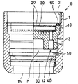
図2を参照して、本体1の周面中間部の外気吸入口3aは環状横溝15を介して負圧形成孔12の下端側の吐出口14と連通している。
第2内部空間7の下半部で、負圧形成孔12の下端側の吐出口14の存在する負圧形成内装部品10の下面と、第3内部空間9のメッシュ板3の上面との間に空間Hが形成され、該空間Hの下方に、整流リング40、2枚のメッシュ板30がスナップリング50で本体1に固定されている。整流リング40は、図7を参照して、斜面41、開口40、周縁部43を有する形状である。60はパッキンである。
【0017】
かくして、負圧形成内装部品10は、流入口より、吐水口のほうが、大径の管(負圧形成孔)内を通ることにより、径の差が生じる場所に負圧ができ、その発生箇所に横穴(外気に連通する管横断方向の通路)(環状横溝15および外気吸入口3a)を設けている。
すなわち、環状横溝 15 の内芯端 15 aは吐出口 14 と接触する位置Pでは開口していることで、吐出口 14 は環状横溝 15 とに連通し、環状横溝 15 の周縁に 外気吸入口3aが連通していることで、吐出口 14 の負圧発生箇所は、環状横溝 15 を介して本体の外気吸入口3aに連通
している。その結果、環状横溝 15 および外気吸入口3aは、吐出口 14 に対して、外気との通風口のような役割りを生じることで、それにより、キャビテーションの発生を抑えることができ、高圧を噴射することができる。
【0018】
吐水先(第2内部空間7の下半部H)の高圧水は、整流リング40により整流されたのち、に、メッシュ面21を通過することにより、高圧でありながら、空気混入量の多い、泡沫状の水流が可能になる。
【0019】
かくして、図8を参照して、給水金具(蛇口)Aに取付けた本願発明の給水活性化装置Bは、高圧でありながら、空気混入量の多い、泡沫状の水流が可能になる。給水活性化装置Bの下端よりは、高圧で、且つ、空気混入量の多い、泡沫状のジェット水流Pがほぼ垂直状に放水されることとなる。
【0020】
調整板20により有効な流入口の個数を選択自在としたので、水圧低下に対応できると共に、節水効果を発揮することができる。
【0021】
第3内部空間9に位置して、活性炭メッシュ板、セラミックメッシュ板を装備することで、
高速にて噴射される水流を活性炭や、セラミックにぶつけることにより、いやし効果を生み出すことができる。
【0022】
【効果】
本願発明の給水活性化装置Bは、低水圧時でも、空気を混入し、ジェット水流に変化することにより、少ない水量でも、高圧な吐水が可能になり、大幅な節水が行え、低水圧から高水圧の範囲で泡沫状の吐水が行い得る効果を有する。
上記の泡沫状の吐水が行うために、負圧発生箇所(径の差が生じる場所)に外気を供給するための横穴(外気に連通する管横断方向の通路)を形成するための手段として、環状横溝 15 を介して本体の外気吸入口3aに連通させたから、外気吸入口3a通じる管放射方向の直線的空間に環状横溝 15 による空間が存在することで迂回通路が形成可能である。
外気吸入口3aと対向する位置に塵埃等が付着した場合でも迂回して外気吸入口3aと吐出口 14 との連通が可能であり、さらに、外気吸入口3aは複数個形成されていることで、一部の外気吸入口3aに塵埃か付着した場合においても他の有効な外気吸入口3aより環状横溝 15 を円周方向に迂回して有効な横穴(外気に連通する管横断方向の通路)を維持して、吐出口 14 と外気との連通状態を確保して、泡沫状の吐水を確実に維持することができる。
【図面の簡単な説明】
【図1】本願発明の実施例を示す給水活性化装置の斜視図。
【図2】同じく縦断面図。
【図3】筒状の本体示し、a図は部分断面した正面図、b図は平面図。
【図4】負圧形成内装部品を示し、a図は平面図、b図は部分断面した正面図。
【図5】調整板を示し、a図は平面図、b図は正面図。
【図6】メッシュ板を示し、a図は平面図、b図は縦断面図。
【図7】整流リングを示し、a図は平面図、b図は縦断面。
【図8】給水活性化装置の使用状態を示す略図。
【符号の説明】
1 筒状
3 外気吸入口
10 負圧形成内装部品
12 負圧形成孔
13 流入口
14 吐出口
15 環状横溝
20 調整板
30 メッシュ板
40 整流リング
50 スナップリング[0001]
BACKGROUND OF THE INVENTION
The present invention relates to a water supply auxiliary tool attached to the tip (for example, a faucet) of a water supply channel. More specifically, the present invention relates to a water supply activation device for activating tap water.
[0002]
[Prior art]
Regarding this type of water supply activation device, Japanese Patent Application Laid-Open No. 11-300364, “Active Water Forming Device” (Patent Document 1) and Japanese Patent Application Laid-Open No. 11-104523, “Hair Wash Table Shower Head” (Patent Document) 2) exists. In any case, tap water is activated, and an air-jet is formed from the outside air sucked from the small intake holes using negative pressure, and this mixed jet is discharged from the small discharge holes.
There is a problem that there is almost no water-saving function and air may not be mixed in due to a change in water supply pressure.
In addition, the method of restricting the flow rate by providing a valve using an orifice or the like at the inlet of the foam generating part and then flowing into the foam part is easily affected by the inflow pressure. There was a problem that it did not become foam.
[0003]
[Patent Document 1]
Japanese Patent Laid-Open No. 11-300234 [Patent Document 2]
Japanese Patent Laid-Open No. 11-104523,
[0004]
[Problems to be solved by the invention]
This invention makes it a subject to achieve the objective of activation more than the change of the amount of water supply in the water supply activation apparatus for activating tap water.
[0005]
[Means for Solving the Problems]
The water supply activation device of the invention of the present application is a water supply activation device in which a negative pressure forming
In the negative
[0006]
DETAILED DESCRIPTION OF THE INVENTION
Hereinafter, the present invention will be described in detail based on embodiments shown in the drawings.
[0007]
Referring to FIGS. 1 and 2,
[0008]
Referring to FIG. 3, in addition to
[0009]
The negative pressure forming
[0010]
It penetrates 10 negative
[0011]
An
[0012]
With reference to FIG. 5, the adjusting
[0013]
With the
[0014]
FIG. 6 shows a
[0015]
In the assembled state, referring to FIG. 2,
[0016]
Referring to FIG. 2, the outside air suction port 3 a at the middle portion of the peripheral surface of the
In the lower half of the second
[0017]
Thus, the negative pressure forming
In other words, by the inner core end 15 a of the annular
is doing. As a result, the annular
[0018]
The high-pressure water at the water discharge destination (the lower half H of the second internal space 7) is rectified by the rectifying
[0019]
Thus, referring to FIG. 8, the water supply activation device B of the present invention attached to the water supply fitting (faucet) A enables a foamy water flow with a large amount of air mixing while being high pressure. From the lower end of the water supply activation device B, a foamy jet water flow P having a high pressure and a large amount of air mixing is discharged in a substantially vertical shape.
[0020]
Since the number of effective inflow ports can be freely selected by the adjusting
[0021]
By being equipped with activated carbon mesh plate and ceramic mesh plate in the third
A healing effect can be produced by hitting activated water or ceramics with a water stream injected at high speed.
[0022]
【effect】
The water supply activation device B of the present invention is capable of discharging water at a high pressure even with a small amount of water by mixing air and changing into a jet water flow even at low water pressure, and can perform significant water saving. It has the effect that foamy water discharge can be performed in the range of water pressure.
In order to perform the foamy water discharge, as a means for forming a lateral hole (passage in the tube transverse direction communicating with the outside air) for supplying the outside air to the negative pressure generation location (where the difference in diameter occurs) because I is communicated with the outside air inlet 3a of the body via an annular
Even when dust or the like adheres to a position facing the outside air intake port 3a, the outside air intake port 3a and the
[Brief description of the drawings]
FIG. 1 is a perspective view of a water supply activation device showing an embodiment of the present invention.
FIG. 2 is a longitudinal sectional view.
FIGS. 3A and 3B show a cylindrical main body, in which FIG. 3a is a partially sectional front view, and FIG.
4A and 4B show a negative pressure forming interior part, in which FIG. A is a plan view, and FIG.
FIGS. 5A and 5B show an adjustment plate, in which FIG. A is a plan view and FIG. B is a front view;
6A and 6B show a mesh plate, in which FIG. A is a plan view and FIG.
7A and 7B show a rectifying ring, in which FIG. A is a plan view and FIG.
FIG. 8 is a schematic diagram showing a use state of the water supply activation device.
[Explanation of symbols]
1
10 Negative pressure forming interior parts
12 Negative pressure forming hole
13 Inlet
14 Discharge port
15 Annular transverse groove
20 Adjustment plate
30 mesh board
40 Rectifier ring
50 snap ring
Claims (3)
負圧形成内装部材品10の負圧形成孔12における、上端側の流入口13に対し大径である下端側の吐出口14を、環状横溝 15 を介して、本体の外気吸入口3aに連通させたことを特徴とする給水活性化装置。 In a water supply activation device in which a negative pressure forming interior member 10 can be freely inserted into a cylindrical main body 1 having a plurality of outside air inlets 3 formed in an intermediate portion of an outer peripheral surface,
In the negative pressure forming hole 12 of the negative pressure forming interior member product 10, the discharge port 14 on the lower end side having a larger diameter than the inflow port 13 on the upper end side is communicated with the outside air intake port 3 a of the main body via the annular lateral groove 15. A water supply activation device characterized by having been made.
Priority Applications (1)
| Application Number | Priority Date | Filing Date | Title |
|---|---|---|---|
| JP2003095112A JP4235802B2 (en) | 2003-03-31 | 2003-03-31 | Water supply activation device |
Applications Claiming Priority (1)
| Application Number | Priority Date | Filing Date | Title |
|---|---|---|---|
| JP2003095112A JP4235802B2 (en) | 2003-03-31 | 2003-03-31 | Water supply activation device |
Publications (3)
| Publication Number | Publication Date |
|---|---|
| JP2004300780A JP2004300780A (en) | 2004-10-28 |
| JP2004300780A5 JP2004300780A5 (en) | 2006-06-15 |
| JP4235802B2 true JP4235802B2 (en) | 2009-03-11 |
Family
ID=33407512
Family Applications (1)
| Application Number | Title | Priority Date | Filing Date |
|---|---|---|---|
| JP2003095112A Expired - Lifetime JP4235802B2 (en) | 2003-03-31 | 2003-03-31 | Water supply activation device |
Country Status (1)
| Country | Link |
|---|---|
| JP (1) | JP4235802B2 (en) |
Families Citing this family (3)
| Publication number | Priority date | Publication date | Assignee | Title |
|---|---|---|---|---|
| JP2007162400A (en) * | 2005-12-15 | 2007-06-28 | Kazumi Doinai | Water-saving disk structure |
| GB2464779B (en) * | 2009-04-09 | 2010-09-22 | A L Challis Ltd | Air inductor |
| KR101199501B1 (en) * | 2010-11-05 | 2012-11-09 | (주)엠이씨 | Micro bubble nozzle |
-
2003
- 2003-03-31 JP JP2003095112A patent/JP4235802B2/en not_active Expired - Lifetime
Also Published As
| Publication number | Publication date |
|---|---|
| JP2004300780A (en) | 2004-10-28 |
Similar Documents
| Publication | Publication Date | Title |
|---|---|---|
| US6739523B2 (en) | Multi-functional shower head | |
| US8459304B2 (en) | Air intake module of water feeding apparatus | |
| EP2401089B1 (en) | Showerhead | |
| CN105937255A (en) | Jet regulator | |
| US20050205697A1 (en) | Combination showerhead with waterfall nozzle | |
| JP4235802B2 (en) | Water supply activation device | |
| CN101649634B (en) | Jet aerator and sanitary water outlet part | |
| KR100906617B1 (en) | Water-saving shower head and manufacturing method thereof | |
| CN107190816A (en) | Jet regulator | |
| CN215669891U (en) | Novel rotatory bubbler that switches | |
| JP2008541900A (en) | shower head | |
| CN113550388A (en) | Novel rotatory bubbler that switches | |
| JP2020031785A (en) | Shower head device | |
| JP2590832Y2 (en) | Foamed shower head | |
| CN210700701U (en) | Annular particle spray water outlet device and shower head | |
| JP2528371Y2 (en) | Foamed shower head | |
| CA2715925C (en) | Air intake module of water feeding apparatus | |
| WO2022004194A1 (en) | Water discharge part structure for faucet, and faucet provided with same | |
| JP2007301561A (en) | Gas bubble breaking nozzle | |
| WO2023005510A1 (en) | Ejector, dispense device and laundry treatment apparatus | |
| JP3632279B2 (en) | Shower water discharger and water purifier | |
| CN209886015U (en) | Water-saving water outlet device of atomizing nozzle | |
| JP2004132138A (en) | Bubble diffusion nozzle | |
| WO2020044847A1 (en) | Shower head device | |
| JPH10211249A (en) | Bath water jet device for bathtub |
Legal Events
| Date | Code | Title | Description |
|---|---|---|---|
| A521 | Request for written amendment filed |
Free format text: JAPANESE INTERMEDIATE CODE: A523 Effective date: 20060327 |
|
| A621 | Written request for application examination |
Free format text: JAPANESE INTERMEDIATE CODE: A621 Effective date: 20060327 |
|
| A521 | Request for written amendment filed |
Free format text: JAPANESE INTERMEDIATE CODE: A523 Effective date: 20060424 |
|
| A977 | Report on retrieval |
Free format text: JAPANESE INTERMEDIATE CODE: A971007 Effective date: 20080612 |
|
| A131 | Notification of reasons for refusal |
Free format text: JAPANESE INTERMEDIATE CODE: A131 Effective date: 20080701 |
|
| A521 | Request for written amendment filed |
Free format text: JAPANESE INTERMEDIATE CODE: A523 Effective date: 20080829 |
|
| TRDD | Decision of grant or rejection written | ||
| A01 | Written decision to grant a patent or to grant a registration (utility model) |
Free format text: JAPANESE INTERMEDIATE CODE: A01 Effective date: 20081104 |
|
| A01 | Written decision to grant a patent or to grant a registration (utility model) |
Free format text: JAPANESE INTERMEDIATE CODE: A01 |
|
| A61 | First payment of annual fees (during grant procedure) |
Free format text: JAPANESE INTERMEDIATE CODE: A61 Effective date: 20081202 |
|
| R150 | Certificate of patent or registration of utility model |
Ref document number: 4235802 Country of ref document: JP Free format text: JAPANESE INTERMEDIATE CODE: R150 Free format text: JAPANESE INTERMEDIATE CODE: R150 |
|
| FPAY | Renewal fee payment (event date is renewal date of database) |
Free format text: PAYMENT UNTIL: 20111226 Year of fee payment: 3 |
|
| FPAY | Renewal fee payment (event date is renewal date of database) |
Free format text: PAYMENT UNTIL: 20121226 Year of fee payment: 4 |
|
| R250 | Receipt of annual fees |
Free format text: JAPANESE INTERMEDIATE CODE: R250 |
|
| FPAY | Renewal fee payment (event date is renewal date of database) |
Free format text: PAYMENT UNTIL: 20131226 Year of fee payment: 5 |
|
| R250 | Receipt of annual fees |
Free format text: JAPANESE INTERMEDIATE CODE: R250 |
|
| R250 | Receipt of annual fees |
Free format text: JAPANESE INTERMEDIATE CODE: R250 |
|
| R250 | Receipt of annual fees |
Free format text: JAPANESE INTERMEDIATE CODE: R250 |
|
| R250 | Receipt of annual fees |
Free format text: JAPANESE INTERMEDIATE CODE: R250 |
|
| R250 | Receipt of annual fees |
Free format text: JAPANESE INTERMEDIATE CODE: R250 |
|
| R250 | Receipt of annual fees |
Free format text: JAPANESE INTERMEDIATE CODE: R250 |
|
| R250 | Receipt of annual fees |
Free format text: JAPANESE INTERMEDIATE CODE: R250 |
|
| R250 | Receipt of annual fees |
Free format text: JAPANESE INTERMEDIATE CODE: R250 |
|
| R250 | Receipt of annual fees |
Free format text: JAPANESE INTERMEDIATE CODE: R250 |
|
| R250 | Receipt of annual fees |
Free format text: JAPANESE INTERMEDIATE CODE: R250 |
|
| R250 | Receipt of annual fees |
Free format text: JAPANESE INTERMEDIATE CODE: R250 |
|
| EXPY | Cancellation because of completion of term |