JP4235586B2 - Paper feeder - Google Patents
Paper feeder Download PDFInfo
- Publication number
- JP4235586B2 JP4235586B2 JP2004164384A JP2004164384A JP4235586B2 JP 4235586 B2 JP4235586 B2 JP 4235586B2 JP 2004164384 A JP2004164384 A JP 2004164384A JP 2004164384 A JP2004164384 A JP 2004164384A JP 4235586 B2 JP4235586 B2 JP 4235586B2
- Authority
- JP
- Japan
- Prior art keywords
- sheet
- paper
- guide wall
- downstream
- conveyed
- Prior art date
- Legal status (The legal status is an assumption and is not a legal conclusion. Google has not performed a legal analysis and makes no representation as to the accuracy of the status listed.)
- Active
Links
Images


Classifications
-
- B—PERFORMING OPERATIONS; TRANSPORTING
- B65—CONVEYING; PACKING; STORING; HANDLING THIN OR FILAMENTARY MATERIAL
- B65H—HANDLING THIN OR FILAMENTARY MATERIAL, e.g. SHEETS, WEBS, CABLES
- B65H3/00—Separating articles from piles
- B65H3/08—Separating articles from piles using pneumatic force
- B65H3/12—Suction bands, belts, or tables moving relatively to the pile
-
- B—PERFORMING OPERATIONS; TRANSPORTING
- B65—CONVEYING; PACKING; STORING; HANDLING THIN OR FILAMENTARY MATERIAL
- B65H—HANDLING THIN OR FILAMENTARY MATERIAL, e.g. SHEETS, WEBS, CABLES
- B65H3/00—Separating articles from piles
- B65H3/46—Supplementary devices or measures to assist separation or prevent double feed
- B65H3/56—Elements, e.g. scrapers, fingers, needles, brushes, acting on separated article or on edge of the pile
-
- B—PERFORMING OPERATIONS; TRANSPORTING
- B65—CONVEYING; PACKING; STORING; HANDLING THIN OR FILAMENTARY MATERIAL
- B65H—HANDLING THIN OR FILAMENTARY MATERIAL, e.g. SHEETS, WEBS, CABLES
- B65H3/00—Separating articles from piles
- B65H3/08—Separating articles from piles using pneumatic force
- B65H3/12—Suction bands, belts, or tables moving relatively to the pile
- B65H3/124—Suction bands or belts
- B65H3/128—Suction bands or belts separating from the top of pile
-
- B—PERFORMING OPERATIONS; TRANSPORTING
- B65—CONVEYING; PACKING; STORING; HANDLING THIN OR FILAMENTARY MATERIAL
- B65H—HANDLING THIN OR FILAMENTARY MATERIAL, e.g. SHEETS, WEBS, CABLES
- B65H2511/00—Dimensions; Position; Numbers; Identification; Occurrences
- B65H2511/50—Occurence
- B65H2511/51—Presence
Abstract
Description
本発明は、給紙台上に積み重ねられた用紙を上から1枚ずつ分離して搬送する給紙装置に関するものである。 The present invention relates to a paper feeding device that separates and transports sheets stacked on a paper feeding table one by one from the top.
例えば、特許文献1には、用紙加工装置が示されている。この用紙加工装置では、給紙装置によって、用紙を1枚ずつ搬送して加工装置本体に給紙し、加工装置本体において、用紙を搬送しながら、搬送方向や直行方向に裁断加工したり、折り型形成加工したりするようになっている。また、例えば、特許文献2には、給紙装置において用紙を1枚ずつ吸着して搬送する技術、が示されている。更に、例えば、特許文献3には、給紙装置において、給紙カセットが給紙位置にある時にはサバキ部材をサバキ箇所に位置させ、給紙カセットが給紙位置にない時にはサバキ部材をサバキ箇所から退避させる技術、が示されている。
For example, Patent Document 1 discloses a paper processing apparatus. In this paper processing apparatus, the paper is conveyed one by one by the paper feeding device and fed to the main body of the processing apparatus, and while the paper is being conveyed in the main body of the processing apparatus, the paper is cut or folded in the conveyance direction or the orthogonal direction. It is designed to mold. Further, for example,
ところで、特許文献1の用紙加工装置では、例えば、用紙を搬送方向に裁断する加工は、用紙の一側縁を基準として行われる。そのため、特許文献1、2の給紙装置では、用紙の一側縁をガイド壁に沿わせて給紙するようになっている。
By the way, in the paper processing apparatus of Patent Document 1, for example, processing for cutting the paper in the transport direction is performed with reference to one side edge of the paper. Therefore, in the paper feeders of
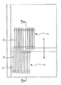
図3は用紙の一側縁をガイド壁に沿わせて給紙する構成を有する給紙装置の平面図である。この給紙装置は、搬送方向(矢印A方向)の上流側に位置する吸着搬送手段2と、下流側に位置する斜行搬送手段3と、が一体となって構成されている。図4は従来の給紙装置の縦断面模式図であり、図3のIV−IV断面に相当する図である。吸着搬送手段2は、給紙台11上に積み重ねられた用紙10の一番上の用紙10を吸着して搬送方向の上流側から下流側へ搬送する。斜行搬送手段3は、用紙10を載せて、用紙10の一側縁をガイド壁31に沿わせるよう用紙10をガイド壁31に向けて斜めに搬送しながら、搬送方向下流へ向けて搬送する。そして、吸着搬送手段2の下流側の下方には、サバキ部材4が設けられている。サバキ部材4は、吸着搬送手段2により搬送される一番上の用紙10のみの通過を許容する。
FIG. 3 is a plan view of a sheet feeding device having a configuration in which one side edge of a sheet is fed along a guide wall. The sheet feeding device is configured by integrating a
ところで、上記従来の給紙装置においては、図4に示すように、用紙10がサバキ部材4を通過して斜行搬送手段3に載って搬送され始める時、用紙10が未だにサバキ部材4に接触している。その状態は、用紙10の後端102がサバキ部材4を通過するまで続く。用紙10がサバキ部材4に接触したままの状態では、それが障害となって、斜行搬送手段3に載った用紙10が円滑に搬送されなくなる。その結果、用紙10の一側縁がガイド壁31に沿うようになる前に、用紙10が給紙装置から給紙されてしまうという不具合が生じる。
By the way, in the conventional sheet feeding device, as shown in FIG. 4, when the
特許文献3の給紙装置でも、給紙を行う際にはサバキ部材が常にサバキ箇所に位置しているので、同様の不具合が生じる。
Even in the paper feeder of
本発明は、サバキ部材4を通過中の用紙を、斜行搬送手段3によってガイド壁31に向けて斜めに搬送する際に、サバキ部材4が搬送の障害となるのを防止して、斜行搬送手段3による搬送を円滑に行うことができる、給紙装置を提供することを目的とする。
In the present invention, when the sheet passing through the surface member 4 is transported obliquely toward the
請求項1記載の発明は、積み重ねられた用紙の一番上の用紙を吸着して搬送方向の上流側から下流側へ搬送する吸着搬送手段と、吸着搬送手段の下流側に位置し、用紙を載せて、用紙の一側縁をガイド壁に沿わせるよう用紙をガイド壁に向けて斜めに搬送しながら、搬送方向下流へ向けて搬送する、斜行搬送手段と、吸着搬送手段により搬送される一番上の用紙のみの通過を許容するサバキ部材と、を備え、給紙台上に積み重ねられた用紙を上から1枚ずつ分離して搬送する給紙装置において、サバキ部材の下流に位置し、サバキ部材を通過中の用紙を検知する、検知手段と、検知手段が上記通過中の用紙を検知している間、サバキ部材を、上記通過中の用紙から退避させる、退避機構と、を備えており、サバキ部材は、搬送方向下流に向けて上向きに傾斜している突起片からなっており、退避機構は、ピストン機構に連結したアームを下方に引くことによって、突起片の搬送方向下流側の先端の位置を低くするように、構成されている、ことを特徴としている。
The first aspect of the present invention is a suction conveyance means for adsorbing the uppermost sheet of the stacked sheets and conveying the sheet from the upstream side to the downstream side in the conveyance direction, and located downstream of the adsorption conveyance means. The paper is transported by the oblique transport means and the suction transport means for transporting the paper toward the downstream side in the transport direction while transporting the paper obliquely toward the guide wall so that one side edge of the paper is along the guide wall. A sheet member that allows only the top sheet to pass therethrough, and is located downstream of the sheet member in a sheet feeding device that separates and conveys the sheets stacked on the sheet feed table one by one from the top. A detecting unit that detects a sheet passing through the sheet member, and a retracting mechanism that retracts the sheet member from the sheet that is passing while the detecting unit detects the sheet that is passing through. and, spreader member, downstream of the conveyance direction The retraction mechanism is configured to lower the position of the tip on the downstream side in the conveyance direction of the protrusion piece by pulling the arm connected to the piston mechanism downward. It is characterized by that.
請求項1記載の発明によれば、検知手段が、サバキ部材を通過中の用紙を検知している間、退避機構が、サバキ部材を、当該通過中の用紙から退避させるので、当該通過中の用紙を、斜行搬送手段によってガイド壁に向けて斜めに搬送する際に、サバキ部材が搬送の障害となるのを防止して、斜行搬送手段による搬送を円滑に行うことができる。すなわち、用紙を、サバキ部材に邪魔されることなく、斜行搬送手段によって円滑に搬送することができる。したがって、用紙の一側縁がガイド壁に沿わないまま用紙が給紙装置から給紙されてしまうという不具合を、解消できる。よって、その後の裁断などの用紙加工を正確に行わせることができる。 According to the first aspect of the present invention, while the detecting unit detects the paper passing through the paper member, the retracting mechanism retracts the paper member from the paper that is passing. When the sheet is transported obliquely toward the guide wall by the skew transporting means, it is possible to prevent the rust member from obstructing transport and to smoothly transport the sheet by the skew transporting means. That is, the sheet can be smoothly conveyed by the skew conveying means without being disturbed by the buckling member. Therefore, it is possible to solve the problem that the sheet is fed from the sheet feeding device without one side edge of the sheet being along the guide wall. Therefore, subsequent paper processing such as cutting can be performed accurately.
図1は本発明の給紙装置を示す縦断面模式図であり、図3のI−I断面に相当する図である。図1及び図4において、同じ符号は、同じ又は相当する構成要素を示している。本発明の給紙装置は、搬送方向(矢印A方向)の上流側に位置する吸着搬送手段2と、下流側に位置する斜行搬送手段3と、が一体となって構成されている。 FIG. 1 is a schematic longitudinal sectional view showing a paper feeding device according to the present invention, and corresponds to a cross section taken along line II in FIG. 1 and 4, the same reference numerals indicate the same or corresponding components. In the sheet feeding device of the present invention, the suction conveyance means 2 located on the upstream side in the conveyance direction (arrow A direction) and the skew conveyance means 3 located on the downstream side are integrally configured.
具体的には、本発明の給紙装置は、給紙台11上に積み重ねられた用紙10の一番上の用紙10を吸着して搬送方向上流側から下流側へ搬送する吸着搬送手段2と、積み重ねられた用紙10の下流側の先端101に向けて下流側から空気を吹き付ける空気吹付手段(図示せず)と、吸着搬送手段2により搬送される一番上の用紙10のみの通過を許容するサバキ部材6と、用紙10を載せて、用紙10の一側縁をガイド壁31に沿わせるよう用紙10をガイド壁31に向けて斜めに搬送しながら、搬送方向下流へ向けて搬送する、斜行搬送手段3と、を備えている。なお、用紙10は、給紙台11上に積み重ねられ、先端101が給紙台11の下流側の端壁12に当接している。
Specifically, the sheet feeding device of the present invention includes a
吸着搬送手段2は、2個の回転ローラ21間に張り渡された無端環状のベルト22と、ベルト22の下方に位置する用紙10を吸い上げてベルト22に吸着させる吸引手段(図示せず)と、で構成されており、用紙10を、ベルト22に吸着させた状態でベルト22の矢印方向への移動によって下流側へ搬送するようになっている。
The suction conveyance means 2 includes an endless
空気吹付手段は、端壁12を貫通した吹付け部(図示せず)と、吹付け部に接続した空気ブロワ(図示せず)と、を有しており、下流側から吹付け部を通して上流側に向けて空気を吐出するようになっている。
The air blowing means has a blowing portion (not shown) penetrating the
斜行搬送手段3は、吸着搬送手段2によって搬送されてきた用紙10を、2個の回転ローラ32間に張り渡された無端環状のベルト33に載せて、搬送するようになっている。ベルト33は、搬送方向に対してガイド壁31側に向けて少しだけ傾斜して設けられている。したがって、斜行搬送手段3では、用紙10が、ガイド壁31側に押しやられながら搬送されるので、用紙10の一側縁がガイド壁31に沿った状態で矢印A方向に搬送される。
The skew conveying means 3 is configured to carry the
そして、本発明のサバキ部材6は、検知手段7及び退避機構8と共に、設けられている。
In addition, the
サバキ部材6は、給紙台11の端壁12の上方にて且つ吸着搬送手段2の下方にて、立設し且つ搬送方向に向けて傾斜している、突起片61からなっている。
The
検知手段7は、斜行搬送手段3の上流側の端部の上方に設けられたセンサー71からなっている。センサー71は、斜行搬送手段3のベルト33に載せられてきた用紙10の先端101を検知すると、退避機構8に退避信号を送り、当該用紙10の後端102を検知すると、退避機構8に復帰信号を送るようになっている。
The detection means 7 includes a
退避機構8は、ピストン機構81と、ピストン機構81に連結した第1アーム82と、第1アーム82に回動自在に連結した第2アーム83と、からなっており、突出片61を第2アーム83の先端で支持している。図2に示すように、退避機構8は、センサー71から退避信号を受けると、第1アーム82を下方へ引くよう、ピストン機構81を作動させ、それにより、第1アーム82を略直立姿勢とし、それに伴って第2アーム83を回動させて略直立姿勢とし、突起片61の先端611の位置を低くするようになっている。一方、退避機構8は、センサー71から復帰信号を受けると、第1アーム82を上方へ押しやるよう、ピストン機構81を作動させ、それにより、突起片61を、図1の状態、すなわち、サバキを行う状態に、復帰させるようになっている。
The retraction mechanism 8 includes a
次に、上記構成の給紙装置の作動について説明する。
まず、空気吹付手段を作動させて、給紙台11上に積み重ねられた用紙10の上部に向けて、吹付け部から空気を吐出させる。これによって、上部に位置している数枚の用紙10の間に隙間ができ、上部の用紙10が浮き上がって分離しやすくなる。この状態で、吸着搬送手段2の吸引手段を作動させる。これにより、分離しやすくなっている上部の用紙10の内の一番上の用紙10が吸い上げられて、ベルト22に吸着される。そして、回転ローラ21を作動させる。これにより、ベルト22に吸着された用紙10が、ベルト22の移動に伴って、サバキ部材6を通過して、斜行搬送手段3へ搬送される。斜行搬送手段3は、ベルト33上に用紙10を載せて、用紙10をガイド壁31に向けて斜めに搬送しながら、搬送方向下流へ向けて搬送する。これにより、用紙10は、一側縁がガイド壁31に沿った状態で、矢印A方向に給紙される。
Next, the operation of the sheet feeding device having the above configuration will be described.
First, the air blowing means is operated to discharge air from the blowing unit toward the upper part of the
上記作動中において、図1に示すように、用紙10が、吸着搬送手段2によって吸着されて搬送され、サバキ部材6を通過して、先端101が斜行搬送手段3のベルト33に載ると、センサー71が先端101を検知して、退避信号を退避機構8へ送る。退避信号を受けた退避機構8は、上述したように、ピストン機構81を作動させて、図2に示すように、突起片61の先端611の位置を低くする。これにより、サバキ部材6を通過中の用紙10に対して、サバキ部材6は非接触の状態となる。それ故、先端101が斜行搬送手段3のベルト33に載った用紙10は、サバキ部材6に邪魔されることなく、斜行搬送手段3によって円滑に搬送される。したがって、上記構成の給紙装置によれば、用紙10は、斜行搬送手段3によって、用紙10の一側縁が確実にガイド壁31に沿った状態にされて、矢印A方向に給紙される。
During the above operation, as shown in FIG. 1, when the
そして、センサー71は、サバキ部材6を通過してきた用紙10の後端102を検知すると、復帰信号を退避機構8へ送る。復帰信号を受けた退避機構8は、上述したように、ピストン機構81を作動させて、突起片61を、サバキを行う状態に、復帰させる。これにより、吸着搬送手段2によって新たな用紙10が吸着されて搬送され、サバキ部材6を通過する。
When the
以上のように、上記構成の給紙装置によれば、検知手段7が、サバキ部材6を通過中の用紙10を検知している間、退避機構8が、サバキ部材6を、当該通過中の用紙10から退避させるので、用紙10を、サバキ部材6に邪魔されることなく、斜行搬送手段3によって円滑に搬送することができる。したがって、斜行搬送手段3によって、用紙10の一側縁が確実にガイド壁31に沿った状態で、用紙10を給紙できる。
As described above, according to the sheet feeding device having the above-described configuration, while the detection unit 7 detects the
本発明の給紙装置は、用紙の一側縁が確実にガイド壁に沿った状態で、用紙を給紙でき、その後の裁断などの用紙加工を正確に行わせることができるので、産業上の利用価値が大である。 The paper feeding device according to the present invention can feed paper in a state where one side edge of the paper is surely along the guide wall, and can accurately perform paper processing such as subsequent cutting. The utility value is great.
2 吸着搬送手段 3 斜行搬送手段 31 ガイド壁 6 サバキ部材 7 検知手段 8 退避機構
2 Adsorption conveyance means 3 Skew conveyance means 31
Claims (1)
吸着搬送手段の下流側に位置し、用紙を載せて、用紙の一側縁をガイド壁に沿わせるよう用紙をガイド壁に向けて斜めに搬送しながら、搬送方向下流へ向けて搬送する、斜行搬送手段と、
吸着搬送手段により搬送される一番上の用紙のみの通過を許容するサバキ部材と、を備え、
給紙台上に積み重ねられた用紙を上から1枚ずつ分離して搬送する給紙装置において、
サバキ部材の下流に位置し、サバキ部材を通過中の用紙を検知する、検知手段と、
検知手段が上記通過中の用紙を検知している間、サバキ部材を、上記通過中の用紙から退避させる、退避機構と、を備えており、
サバキ部材は、搬送方向下流に向けて上向きに傾斜している突起片からなっており、
退避機構は、ピストン機構に連結したアームを下方に引くことによって、突起片の搬送方向下流側の先端の位置を低くするように、構成されている、ことを特徴とする給紙装置。 Suction conveyance means for sucking the uppermost sheet of the stacked sheets and conveying it from the upstream side to the downstream side in the conveyance direction;
Located on the downstream side of the suction conveyance means, the sheet is loaded, and the sheet is conveyed obliquely toward the guide wall so that one side edge of the sheet is along the guide wall, and conveyed downstream in the conveyance direction. Line conveying means;
A baffle member that allows passage of only the uppermost sheet conveyed by the suction conveyance means,
In a paper feeding device that separates and transports the sheets stacked on the paper feeding table one by one from the top,
A detecting means that is located downstream of the Sabaki member and detects paper passing through the Sabaki member;
A retraction mechanism that retreats the rust member from the passing paper while the detecting means detects the passing paper .
The Sabaki member consists of a protruding piece that is inclined upward toward the downstream in the transport direction,
The retraction mechanism is configured to lower the position of the tip on the downstream side in the conveyance direction of the protruding piece by pulling an arm connected to the piston mechanism downward .
Priority Applications (12)
| Application Number | Priority Date | Filing Date | Title |
|---|---|---|---|
| JP2004164384A JP4235586B2 (en) | 2004-06-02 | 2004-06-02 | Paper feeder |
| TW094105377A TW200540090A (en) | 2004-06-02 | 2005-02-23 | Sheet feeder |
| DE602005019287T DE602005019287D1 (en) | 2004-06-02 | 2005-02-28 | sheet feeder |
| KR1020067013197A KR101151581B1 (en) | 2004-06-02 | 2005-02-28 | Sheet feeder |
| CA2552148A CA2552148C (en) | 2004-06-02 | 2005-02-28 | Sheet feeder |
| RU2006127473/11A RU2373130C2 (en) | 2004-06-02 | 2005-02-28 | Feeding apparatus for feeding of sheets |
| US10/584,452 US7506868B2 (en) | 2004-06-02 | 2005-02-28 | Sheet feeder |
| AU2005249802A AU2005249802B2 (en) | 2004-06-02 | 2005-02-28 | Sheet feeder |
| PCT/JP2005/003293 WO2005118442A1 (en) | 2004-06-02 | 2005-02-28 | Sheet feeder |
| CN200580003310A CN100579882C (en) | 2004-06-02 | 2005-02-28 | Sheet feeder |
| EP05719621A EP1752401B1 (en) | 2004-06-02 | 2005-02-28 | Sheet feeder |
| AT05719621T ATE457281T1 (en) | 2004-06-02 | 2005-02-28 | SHEET FEEDER |
Applications Claiming Priority (1)
| Application Number | Priority Date | Filing Date | Title |
|---|---|---|---|
| JP2004164384A JP4235586B2 (en) | 2004-06-02 | 2004-06-02 | Paper feeder |
Publications (2)
| Publication Number | Publication Date |
|---|---|
| JP2005343621A JP2005343621A (en) | 2005-12-15 |
| JP4235586B2 true JP4235586B2 (en) | 2009-03-11 |
Family
ID=35462841
Family Applications (1)
| Application Number | Title | Priority Date | Filing Date |
|---|---|---|---|
| JP2004164384A Active JP4235586B2 (en) | 2004-06-02 | 2004-06-02 | Paper feeder |
Country Status (12)
| Country | Link |
|---|---|
| US (1) | US7506868B2 (en) |
| EP (1) | EP1752401B1 (en) |
| JP (1) | JP4235586B2 (en) |
| KR (1) | KR101151581B1 (en) |
| CN (1) | CN100579882C (en) |
| AT (1) | ATE457281T1 (en) |
| AU (1) | AU2005249802B2 (en) |
| CA (1) | CA2552148C (en) |
| DE (1) | DE602005019287D1 (en) |
| RU (1) | RU2373130C2 (en) |
| TW (1) | TW200540090A (en) |
| WO (1) | WO2005118442A1 (en) |
Families Citing this family (4)
| Publication number | Priority date | Publication date | Assignee | Title |
|---|---|---|---|---|
| JP2007276912A (en) * | 2006-04-03 | 2007-10-25 | Canon Inc | Sheet feeder and image forming apparatus |
| JP5403489B2 (en) * | 2009-09-10 | 2014-01-29 | 株式会社リコー | Recording medium supply apparatus and image forming apparatus |
| JP6098353B2 (en) * | 2013-05-16 | 2017-03-22 | 株式会社リコー | Paper feeding device and image forming apparatus |
| JP7417379B2 (en) * | 2019-08-09 | 2024-01-18 | 理想科学工業株式会社 | sheet feeding device |
Family Cites Families (16)
| Publication number | Priority date | Publication date | Assignee | Title |
|---|---|---|---|---|
| US2249504A (en) * | 1939-05-25 | 1941-07-15 | Davidson Mfg Corp | Conveyer board |
| DE1267012B (en) | 1964-07-20 | 1968-04-25 | Telefunken Patent | Separator with a device to prevent double draws |
| JPS59108631A (en) | 1982-12-09 | 1984-06-23 | Nec Corp | Ticket delivering device |
| JPS6067343A (en) * | 1983-09-17 | 1985-04-17 | Hashimoto Denki Co Ltd | Automatic sheet feeder |
| JPS60171939A (en) * | 1984-02-14 | 1985-09-05 | Canon Inc | Paper feeder for picture image forming device |
| JPH0629719Y2 (en) * | 1987-09-30 | 1994-08-10 | 株式会社島津製作所 | Material testing machine stop device |
| JPH01133837A (en) * | 1987-11-18 | 1989-05-25 | Toshiba Corp | Take out device for paper sheet |
| JPH061678B2 (en) | 1988-11-24 | 1994-01-05 | 工業技術院長 | External resonance circuit type RFQ accelerator |
| JPH0732062Y2 (en) * | 1989-05-02 | 1995-07-26 | 沖電気工業株式会社 | Passbook issuing mechanism of automatic passbook issuing device |
| US5478066A (en) * | 1992-11-02 | 1995-12-26 | Canon Kabushiki Kaisha | Sheet supply apparatus |
| JPH10167504A (en) * | 1996-12-05 | 1998-06-23 | Canon Inc | Paper feeding device and image forming device equipped with it |
| EP0933318A1 (en) | 1998-01-28 | 1999-08-04 | Grapha-Holding Ag | Device for separating flat objects conveyed from a stack |
| JPH11334901A (en) | 1998-05-20 | 1999-12-07 | Minolta Co Ltd | Paper feeder |
| JP2000010370A (en) | 1998-06-17 | 2000-01-14 | Katsuragawa Electric Co Ltd | Image forming device |
| JP4017756B2 (en) * | 1998-07-16 | 2007-12-05 | デュプロ精工株式会社 | Paper cutting device |
| JP4762394B2 (en) | 2000-02-22 | 2011-08-31 | デュプロ精工株式会社 | Paper cutting device |
-
2004
- 2004-06-02 JP JP2004164384A patent/JP4235586B2/en active Active
-
2005
- 2005-02-23 TW TW094105377A patent/TW200540090A/en unknown
- 2005-02-28 CA CA2552148A patent/CA2552148C/en not_active Expired - Fee Related
- 2005-02-28 AT AT05719621T patent/ATE457281T1/en not_active IP Right Cessation
- 2005-02-28 AU AU2005249802A patent/AU2005249802B2/en not_active Ceased
- 2005-02-28 RU RU2006127473/11A patent/RU2373130C2/en not_active IP Right Cessation
- 2005-02-28 KR KR1020067013197A patent/KR101151581B1/en not_active IP Right Cessation
- 2005-02-28 WO PCT/JP2005/003293 patent/WO2005118442A1/en not_active Application Discontinuation
- 2005-02-28 EP EP05719621A patent/EP1752401B1/en not_active Not-in-force
- 2005-02-28 US US10/584,452 patent/US7506868B2/en active Active
- 2005-02-28 DE DE602005019287T patent/DE602005019287D1/en active Active
- 2005-02-28 CN CN200580003310A patent/CN100579882C/en not_active Expired - Fee Related
Also Published As
| Publication number | Publication date |
|---|---|
| CA2552148C (en) | 2012-05-29 |
| ATE457281T1 (en) | 2010-02-15 |
| DE602005019287D1 (en) | 2010-03-25 |
| RU2373130C2 (en) | 2009-11-20 |
| RU2006127473A (en) | 2008-02-10 |
| EP1752401B1 (en) | 2010-02-10 |
| US7506868B2 (en) | 2009-03-24 |
| AU2005249802B2 (en) | 2010-08-12 |
| CA2552148A1 (en) | 2005-12-15 |
| US20070108692A1 (en) | 2007-05-17 |
| AU2005249802A1 (en) | 2005-12-15 |
| EP1752401A1 (en) | 2007-02-14 |
| KR101151581B1 (en) | 2012-06-01 |
| WO2005118442A1 (en) | 2005-12-15 |
| EP1752401A4 (en) | 2007-08-01 |
| CN1914105A (en) | 2007-02-14 |
| CN100579882C (en) | 2010-01-13 |
| JP2005343621A (en) | 2005-12-15 |
| KR20070020392A (en) | 2007-02-21 |
| TW200540090A (en) | 2005-12-16 |
Similar Documents
| Publication | Publication Date | Title |
|---|---|---|
| JP6098353B2 (en) | Paper feeding device and image forming apparatus | |
| JP5495024B2 (en) | Paper feeding device and image forming apparatus | |
| JP2006213437A (en) | Sheet-like article conveying device | |
| JP4866300B2 (en) | Paper feeding device and electrophotographic device | |
| JP2008280139A (en) | Paper sheet separation and takeout device and its control method | |
| JP5280125B2 (en) | Cross transfer device | |
| JP4235586B2 (en) | Paper feeder | |
| JP2007331905A (en) | Paper feeder, its control method, and printer using this | |
| JP5203819B2 (en) | Paper sheet take-out device | |
| JP2012035978A (en) | Printed book extracting device | |
| JP2007111956A (en) | Booklet opening apparatus for inserting paper | |
| JP2009051657A (en) | Sheet take-out apparatus | |
| JP3959629B2 (en) | Pneumatic paper feeder | |
| JP2008179424A (en) | Paper feeding device | |
| JP2008024456A (en) | Sheet stacking device | |
| JP2011079607A (en) | Printed book extracting device | |
| JP2004043106A (en) | Cut sheet discharging device | |
| JP4766684B2 (en) | Paper transport device | |
| JP3713459B2 (en) | Paper sheet processing equipment | |
| JP2005239310A (en) | Paper feeding device | |
| JPH05306034A (en) | Air type upper sheet taking-up paper feeding device | |
| JPH10120211A (en) | Carry-out method of workpiece inspection device and carry-out mechanism thereof | |
| JP2001038877A (en) | Method for suction-conveying of printing paper with sheet printing press, and paper delivery mechanism therefor | |
| JP2002284381A (en) | Paper sheets processing device | |
| JP2011046458A (en) | Paper feeding device and image forming device |
Legal Events
| Date | Code | Title | Description |
|---|---|---|---|
| A621 | Written request for application examination |
Free format text: JAPANESE INTERMEDIATE CODE: A621 Effective date: 20070419 |
|
| A131 | Notification of reasons for refusal |
Free format text: JAPANESE INTERMEDIATE CODE: A131 Effective date: 20080722 |
|
| A521 | Request for written amendment filed |
Free format text: JAPANESE INTERMEDIATE CODE: A523 Effective date: 20080827 |
|
| TRDD | Decision of grant or rejection written | ||
| A01 | Written decision to grant a patent or to grant a registration (utility model) |
Free format text: JAPANESE INTERMEDIATE CODE: A01 Effective date: 20081202 |
|
| A01 | Written decision to grant a patent or to grant a registration (utility model) |
Free format text: JAPANESE INTERMEDIATE CODE: A01 |
|
| A61 | First payment of annual fees (during grant procedure) |
Free format text: JAPANESE INTERMEDIATE CODE: A61 Effective date: 20081215 |
|
| FPAY | Renewal fee payment (event date is renewal date of database) |
Free format text: PAYMENT UNTIL: 20111219 Year of fee payment: 3 |
|
| R150 | Certificate of patent or registration of utility model |
Ref document number: 4235586 Country of ref document: JP Free format text: JAPANESE INTERMEDIATE CODE: R150 Free format text: JAPANESE INTERMEDIATE CODE: R150 |
|
| FPAY | Renewal fee payment (event date is renewal date of database) |
Free format text: PAYMENT UNTIL: 20111219 Year of fee payment: 3 |
|
| FPAY | Renewal fee payment (event date is renewal date of database) |
Free format text: PAYMENT UNTIL: 20141219 Year of fee payment: 6 |
|
| R250 | Receipt of annual fees |
Free format text: JAPANESE INTERMEDIATE CODE: R250 |
|
| R250 | Receipt of annual fees |
Free format text: JAPANESE INTERMEDIATE CODE: R250 |
|
| R250 | Receipt of annual fees |
Free format text: JAPANESE INTERMEDIATE CODE: R250 |
|
| R250 | Receipt of annual fees |
Free format text: JAPANESE INTERMEDIATE CODE: R250 |
|
| R250 | Receipt of annual fees |
Free format text: JAPANESE INTERMEDIATE CODE: R250 |
|
| R250 | Receipt of annual fees |
Free format text: JAPANESE INTERMEDIATE CODE: R250 |
|
| R250 | Receipt of annual fees |
Free format text: JAPANESE INTERMEDIATE CODE: R250 |
|
| R250 | Receipt of annual fees |
Free format text: JAPANESE INTERMEDIATE CODE: R250 |
|
| R250 | Receipt of annual fees |
Free format text: JAPANESE INTERMEDIATE CODE: R250 |
|
| R250 | Receipt of annual fees |
Free format text: JAPANESE INTERMEDIATE CODE: R250 |