JP4234366B2 - Method for manufacturing clutch gear having boss with spline - Google Patents
Method for manufacturing clutch gear having boss with spline Download PDFInfo
- Publication number
- JP4234366B2 JP4234366B2 JP2002206082A JP2002206082A JP4234366B2 JP 4234366 B2 JP4234366 B2 JP 4234366B2 JP 2002206082 A JP2002206082 A JP 2002206082A JP 2002206082 A JP2002206082 A JP 2002206082A JP 4234366 B2 JP4234366 B2 JP 4234366B2
- Authority
- JP
- Japan
- Prior art keywords
- spline
- clutch gear
- boss portion
- boss
- ring
- Prior art date
- Legal status (The legal status is an assumption and is not a legal conclusion. Google has not performed a legal analysis and makes no representation as to the accuracy of the status listed.)
- Expired - Fee Related
Links
Images


Classifications
-
- F—MECHANICAL ENGINEERING; LIGHTING; HEATING; WEAPONS; BLASTING
- F16—ENGINEERING ELEMENTS AND UNITS; GENERAL MEASURES FOR PRODUCING AND MAINTAINING EFFECTIVE FUNCTIONING OF MACHINES OR INSTALLATIONS; THERMAL INSULATION IN GENERAL
- F16H—GEARING
- F16H55/00—Elements with teeth or friction surfaces for conveying motion; Worms, pulleys or sheaves for gearing mechanisms
- F16H55/02—Toothed members; Worms
- F16H55/17—Toothed wheels
-
- B—PERFORMING OPERATIONS; TRANSPORTING
- B21—MECHANICAL METAL-WORKING WITHOUT ESSENTIALLY REMOVING MATERIAL; PUNCHING METAL
- B21K—MAKING FORGED OR PRESSED METAL PRODUCTS, e.g. HORSE-SHOES, RIVETS, BOLTS OR WHEELS
- B21K1/00—Making machine elements
- B21K1/28—Making machine elements wheels; discs
- B21K1/30—Making machine elements wheels; discs with gear-teeth
-
- F—MECHANICAL ENGINEERING; LIGHTING; HEATING; WEAPONS; BLASTING
- F16—ENGINEERING ELEMENTS AND UNITS; GENERAL MEASURES FOR PRODUCING AND MAINTAINING EFFECTIVE FUNCTIONING OF MACHINES OR INSTALLATIONS; THERMAL INSULATION IN GENERAL
- F16H—GEARING
- F16H55/00—Elements with teeth or friction surfaces for conveying motion; Worms, pulleys or sheaves for gearing mechanisms
- F16H55/02—Toothed members; Worms
- F16H55/17—Toothed wheels
- F16H55/171—Toothed belt pulleys
-
- Y—GENERAL TAGGING OF NEW TECHNOLOGICAL DEVELOPMENTS; GENERAL TAGGING OF CROSS-SECTIONAL TECHNOLOGIES SPANNING OVER SEVERAL SECTIONS OF THE IPC; TECHNICAL SUBJECTS COVERED BY FORMER USPC CROSS-REFERENCE ART COLLECTIONS [XRACs] AND DIGESTS
- Y10—TECHNICAL SUBJECTS COVERED BY FORMER USPC
- Y10T—TECHNICAL SUBJECTS COVERED BY FORMER US CLASSIFICATION
- Y10T29/00—Metal working
- Y10T29/49—Method of mechanical manufacture
- Y10T29/49462—Gear making
- Y10T29/49467—Gear shaping
- Y10T29/49474—Die-press shaping
-
- Y—GENERAL TAGGING OF NEW TECHNOLOGICAL DEVELOPMENTS; GENERAL TAGGING OF CROSS-SECTIONAL TECHNOLOGIES SPANNING OVER SEVERAL SECTIONS OF THE IPC; TECHNICAL SUBJECTS COVERED BY FORMER USPC CROSS-REFERENCE ART COLLECTIONS [XRACs] AND DIGESTS
- Y10—TECHNICAL SUBJECTS COVERED BY FORMER USPC
- Y10T—TECHNICAL SUBJECTS COVERED BY FORMER US CLASSIFICATION
- Y10T74/00—Machine element or mechanism
- Y10T74/19—Gearing
- Y10T74/19949—Teeth
- Y10T74/19963—Spur
Description
【0001】
【発明の属する技術分野】
本発明は、周面にドッグクラッチ歯を有したクラッチギヤの側面に、そのクラッチギヤより小径のボス部が設けられ、そのボス部の周面にスプラインが形成されているスプライン付きボス部を有するクラッチギヤの製造方法に関する。
【0002】
【従来の技術】
スプライン付きボス部を有するクラッチギヤは、スプラインの有効部分をクラッチギヤの端面レベルまで確保したくとも、クラッチギヤの側面にボス部が一体成型されたワークでは、切削手段にしろ鍛造手段にしろ、不可能視されている。
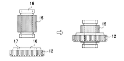
そのためこれまでは、図4に示すように、外周面に外スプライン15が形成された内筒部材16と、内周面に内スプライン17が形成された外筒部材18とを個々に形成し、それら二つの部材をスプライン結合により合体させていた。
外筒部材18の周面にはドッグクラッチ歯12が形成されているので、外筒部材18はクラッチギヤとして機能し、一方、外筒部材18から露出した内筒部材16のスプライン形成部は、嵌合用のボス部として機能する。
而もボス部に形成されているスプライン(外スプライン)15は、有効部分がクラッチギヤの端面レベルまで確保される。
【0003】
【発明が解決しようとする課題】
ところで前記外筒部材と内筒部材とは、例えば図5の(a)に示すように、内筒部材は、丸棒材からカットした円柱状素材19に両端部からポンチを打ち込んで、中間部分が壁体5で塞がれた深穴6,7を形成し、続いてピアス加工で前記壁体5を抜き落とし、次に周面の両端部分に溝20,20を切削加工し、最後に外スプライン15を切削加工して完成させる一方で、外筒部材は、図5の(b)に示すように、丸棒材からカットした円柱素材19をプレスにより扁平に潰すと共に、底付き穴21を凹設し、続いてピアス加工により底部22を抜き落とし、次に端面角部を切削加工した後、内スプライン17を切削加工し、最後にドッグクラッチ歯12を切削加工して完成させている。
各部材の加工方法は前記以外に種々あるが、いずれも工程数が多く、而も2部材を形成し、それらを合体させなくてはならないので効率が悪い。
【0004】
【課題を解決するための手段】
本発明は、鍛造手段の有効利用によって一体成型し、効率の向上を図らんとするものであって、その構成は、周面にドッグクラッチ歯を有したクラッチギヤの側面に、そのクラッチギヤより小径のボス部をクラッチギヤと同軸で一体に形成すると共に、ボス部側に、内壁面が前記ボス部と同径で、外壁面が、底に近づくに従って溝幅を徐々に狭くしてスプライン形成用歯型を有するダイの筒状部を中心側へ押圧する傾斜となるリング状溝を設け、そのクラッチギヤを、前記ボス部の周面に対応する部分に前記ダイ内に対し相対的に押し込むことで、ボス部の周面からリング状溝の内壁面にかけてスプラインを形成することを特徴としたスプライン付きボス部を有するクラッチギヤの製造方法にある。
【0005】
【発明の実施の形態】
本発明に係るスプライン付きボス部を有するクラッチギヤ及びその製造方法を図面に基づいて説明する。
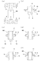
図1は製造工程を示したもので、丸棒をカットして形成された円柱状の素材W1(図1のa)の周囲を上型1と下型2とで拘束し、両端面からポンチ3,4を打ち込んで中間部分が壁体5で塞がれた深穴6,7を形成すると同時に、外周面にフランジ状の円盤部8を張り出させる。
又この際、円盤部8には、片側面にその円盤部8の張り出し基端部を内径とするリング状溝9が凹設すると共に、円盤部8の外周にドッグクラッチ歯12を形成するが、それによって円盤部の外周面に沿って不必要なバリ10が生ずる(図1のb)。
それに続く工程では、ピアス加工により前記壁体5を抜き落として軸穴が設けられた筒状本体11を形成すると共に、バリ10を切除し、筒状本体の周囲にリング状溝9付きの円盤部8を有した成形品W2を形成する(図1のc)。
【0006】
更に、形成された成形品W2における筒状本体11の端部を切削加工し、これを次の工程で使用するワークW3とする。
そして次の工程では、このワークW3におけるリング状溝9が形成されている側の筒状本体11(ボス部)の外周に、リング状溝9内の内壁面に連続したスプライン13を形成する。
このスプライン13は、ワークW3をボス部11に対応する部分にスプライン形成用歯型を有したダイに対して相対的に押し込むといった鍛造手段を利用して形成することができる。
尚、上記ダイに対して相対的に押し込むとは、ワークをダイに押し込む場合と、それとは逆にダイ(パンチ)をワークに押し込む場合とが含まれる。
最後に、筒状本体の端部周面と内周部とを加工することで製品W4が完成される。
【0007】
このようにして形成されたスプライン付きボス部を有するクラッチギヤは、周面にドッグクラッチ歯を有したクラッチギヤの側面に、そのクラッチギヤより小径で、周面にスプラインが形成されたボス部が、鍛造により前記クラッチギヤと同軸で一体に形成されており、前記スプラインはリング状溝内の内壁面まで連続している。
即ち、一体型でありながらスプラインの有効部分がクラッチギヤの端面レベルにまで及んでいるのである。
【0008】
一体成形品とすることで、2部材を個々に形成して合体させる場合に比べ、工程数は半減し、その実現は、リング状溝を形成することにより可能である。
【0009】
スプラインの形成は、リング状溝を工具の逃げが確保できるよう拡大し、切削で形成することについては何ら差し支えない。
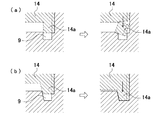
鍛造手段でスプラインを形成する場合、ワークのボス部に対応する部分にスプライン形成用歯型を有したダイで、リング状溝内まで連続したスプラインを形成しようとすると、ダイの先はリング状溝に対応した筒状にしなくてはならないが、ダイ14には塑性抵抗により外方に膨らもうとする強い応力が作用するので、図2の(a)に示すように、外周が拘束されていない筒状部分14aは破損しやすい。
本実施例では、リング状溝の外壁面に、底に近づくに従って溝幅を徐々に狭くするための傾斜を設けることで、図2の(b)に示すように、筒状部14aがリング状溝9内に押し込まれる際、傾斜面により中心側に押し付けられ、押し付けられる反力と塑性抵抗とが釣り合って破損が防止されるようになっている。
尚、筒状部の外周面にも傾斜を設けておけば、反力をより高くできる。
【0010】
実施例はクラッチギヤの両端にボス部を備えた製品について説明したが、ボス部は片側のみでもかまわないし、両側のボス部にスプラインを設けたり、ドッグクラッチ歯に逆テーパを形成したり或いはしなかったりするなど、適宜設計変更可能であるし、予め円盤部のボス部側にリング状溝を形成しておくことなく、図3に示すように、パンチ14の押し込み力でスプラインの端部を円盤部の側面内方へ沈み込むように形成しても差し支えない。
この場合、円盤部の側面に沈み込むように形成されたスプラインの周りには、パンチが押し付けられた凹状の跡が残る。
【0011】
【発明の効果】
スプラインの有効部分がクラッチギヤの端面レベルにまで及んでいる一体成型によるスプライン付きボス部を有するクラッチギヤは、製造工程数がこれまでの製品と比べて格段に少ないし、接合部分がないので強度的な面における信頼性も高い。
そして、リング状溝の形成によって、ボス部を短縮でき、小型化を図ることができる。
又、リング状溝の外壁面に、底に近づくに従って溝幅を徐々に狭くしてスプライン形成用歯型を有するダイの筒状部を中心側へ押圧する傾斜を設けているので、リング状溝内の奥深くまでスプラインを連続して形成する場合でも型が破損することはなく、端面より沈み込んだ部分までスプラインを形成することができ、理想の成形品を得ることができる。
【図面の簡単な説明】
【図1】 本発明に係るスプライン付きボス部を有するクラッチギヤの製造工程を示す説明図である。
【図2】スプラインを鍛造にて形成する場合、リング状溝の内壁面にテーパを設けることによる利点を説明した説明図である。
【図3】パンチの押し込み力でスプラインの端部を円盤部の側面内方へ沈み込むように形成する変更例の説明図である。
【図4】従来のスプライン付きボス部を有するクラッチギヤを製造する際の合体方法を示した説明図である。
【図5】各部材の製造工程を示した説明図である。
【符号の説明】
1・・上型、2・・下型、3、4・・ポンチ、5・・壁体、6、7・・深穴、8・・円盤部、9・・リング状溝、10・・バリ、11・・筒状本体(ボス部)、12・・ドッグクラッチ歯、13・・スプライン、14・・ダイ、14a・・筒状部、15・・外スプライン、16・・内筒部材、17・・内スプライン、18・・外筒部材、19・・円柱状素材、20・・溝、21・・底付き穴、22・・底部、W1・・円柱状素材、W2・・成形品、W3・・ワーク、W4・・製品。[0001]
BACKGROUND OF THE INVENTION
The present invention has a boss portion with a spline in which a boss portion having a smaller diameter than the clutch gear is provided on a side surface of a clutch gear having dog clutch teeth on the peripheral surface, and a spline is formed on the peripheral surface of the boss portion. The present invention relates to a method for manufacturing a clutch gear.
[0002]
[Prior art]
For clutch gears with splined bosses, even if it is desired to secure the effective part of the spline up to the end face level of the clutch gear, the workpiece with the boss part integrally formed on the side surface of the clutch gear, whether cutting or forging means, It seems impossible.
Therefore, until now, as shown in FIG. 4, the
Since the
In addition, the spline (outer spline) 15 formed in the boss portion has an effective portion secured to the end face level of the clutch gear.
[0003]
[Problems to be solved by the invention]
By the way, as shown in FIG. 5 (a), for example, the outer cylinder member and the inner cylinder member are formed by punching punches from both ends into a
There are various methods for processing each member other than those described above, but all have a large number of steps, and it is inefficient because two members must be formed and combined.
[0004]
[Means for Solving the Problems]
The present invention is intended to improve the efficiency by integrally molding by effectively using forging means, and the structure is provided on the side surface of the clutch gear having dog clutch teeth on the peripheral surface from the clutch gear. A small-diameter boss part is formed coaxially with the clutch gear, and the spline is formed on the boss part side with the inner wall surface having the same diameter as the boss part and the outer wall surface gradually becoming narrower as it approaches the bottom. An annular ring groove is provided to press the cylindrical portion of the die having the tooth shape toward the center, and the clutch gear is pushed into the portion corresponding to the peripheral surface of the boss portion relative to the inside of the die. it is, in producing how the clutch gear having a splined boss portion characterized by forming a spline from the circumferential surface of the boss portion to the inner wall surface of the ring-shaped groove.
[0005]
DETAILED DESCRIPTION OF THE INVENTION
A clutch gear having a splined boss according to the present invention and a manufacturing method thereof will be described with reference to the drawings.
FIG. 1 shows a manufacturing process. A cylindrical material W1 (a in FIG. 1) formed by cutting a round bar is constrained by an
At this time, the
In a subsequent process, the
[0006]
Further, the end portion of the cylindrical
In the next step, a
The
Note that the relative pushing with respect to the die includes a case where the workpiece is pushed into the die and a case where the die (punch) is pushed into the workpiece.
Finally, the product W4 is completed by processing the end peripheral surface and the inner peripheral portion of the cylindrical main body.
[0007]
The clutch gear having the splined boss portion formed in this way has a boss portion having a smaller diameter than the clutch gear and a spline formed on the peripheral surface on the side surface of the clutch gear having dog clutch teeth on the peripheral surface. The spline is integrally formed coaxially with the clutch gear by forging, and the spline continues to the inner wall surface in the ring-shaped groove.
That is, the effective part of the spline extends to the end face level of the clutch gear while being integrated.
[0008]
By using an integrally molded product, the number of processes is halved compared to the case where the two members are individually formed and united, and this can be realized by forming a ring-shaped groove.
[0009]
The spline can be formed by enlarging the ring-shaped groove so that the escape of the tool can be ensured, and forming it by cutting.
When forming a spline by forging means, if you try to form a spline that continues to the inside of the ring groove with a die that has a spline forming tooth mold in the part corresponding to the boss part of the workpiece, the tip of the die will be a ring groove However, since the
In this embodiment, by providing the outer wall surface of the ring-shaped groove with an inclination for gradually narrowing the groove width toward the bottom, as shown in FIG. When pushed into the
In addition, if the outer peripheral surface of the cylindrical portion is also inclined, the reaction force can be further increased.
[0010]
Although the embodiment has been described for products having bosses at both ends of the clutch gear, the bosses may be on one side only, splines are provided on the bosses on both sides, or reverse taper is formed on the dog clutch teeth. The design of the spline can be changed as appropriate, and the end of the spline can be moved by the pressing force of the
In this case, a concave mark where the punch is pressed remains around the spline formed so as to sink into the side surface of the disk portion.
[0011]
【The invention's effect】
Clutch gears with splined bosses that have an integral spline that extends to the end face level of the clutch gear have a significantly smaller number of manufacturing steps than conventional products, and there are no joints. Highly reliable in terms of quality.
And by forming the ring-shaped groove, the boss portion can be shortened and the size can be reduced.
Also, since the outer wall surface of the ring-shaped groove is provided with a slope that gradually narrows the groove width toward the bottom and presses the cylindrical portion of the die having the spline forming tooth mold toward the center side. Even when the spline is continuously formed deep inside, the mold is not damaged, and the spline can be formed from the end surface to the depressed portion, and an ideal molded product can be obtained.
[Brief description of the drawings]
FIG. 1 is an explanatory view showing a manufacturing process of a clutch gear having a splined boss portion according to the present invention.
FIG. 2 is an explanatory diagram for explaining advantages of providing a taper on the inner wall surface of a ring-shaped groove when a spline is formed by forging.
FIG. 3 is an explanatory diagram of a modified example in which the end of the spline is formed so as to sink into the side surface of the disk portion by the pushing force of the punch.
FIG. 4 is an explanatory view showing a combination method when manufacturing a conventional clutch gear having a splined boss portion.
FIG. 5 is an explanatory view showing a manufacturing process of each member.
[Explanation of symbols]
1 ・ ・ Upper mold, 2 ・ ・ Lower mold, 3,4 ・ ・ Punch, 5 ・ ・ Wall body, 6, 7 ・ ・ Deep hole, 8 ・ ・ Disk part, 9 ・ ・ Ring groove, 10 ・ ・
Claims (1)
Priority Applications (4)
| Application Number | Priority Date | Filing Date | Title |
|---|---|---|---|
| JP2002206082A JP4234366B2 (en) | 2002-07-15 | 2002-07-15 | Method for manufacturing clutch gear having boss with spline |
| US10/618,643 US6935482B2 (en) | 2002-07-15 | 2003-07-15 | Clutch gear having boss part with spline and method for manufacturing the same |
| EP03016043A EP1382407B1 (en) | 2002-07-15 | 2003-07-15 | Clutch gear having boss part with spline and method for manufacturing the same |
| DE60314056T DE60314056T2 (en) | 2002-07-15 | 2003-07-15 | Clutch gear with toothing and method for producing the same |
Applications Claiming Priority (1)
| Application Number | Priority Date | Filing Date | Title |
|---|---|---|---|
| JP2002206082A JP4234366B2 (en) | 2002-07-15 | 2002-07-15 | Method for manufacturing clutch gear having boss with spline |
Publications (2)
| Publication Number | Publication Date |
|---|---|
| JP2004044753A JP2004044753A (en) | 2004-02-12 |
| JP4234366B2 true JP4234366B2 (en) | 2009-03-04 |
Family
ID=29774595
Family Applications (1)
| Application Number | Title | Priority Date | Filing Date |
|---|---|---|---|
| JP2002206082A Expired - Fee Related JP4234366B2 (en) | 2002-07-15 | 2002-07-15 | Method for manufacturing clutch gear having boss with spline |
Country Status (4)
| Country | Link |
|---|---|
| US (1) | US6935482B2 (en) |
| EP (1) | EP1382407B1 (en) |
| JP (1) | JP4234366B2 (en) |
| DE (1) | DE60314056T2 (en) |
Families Citing this family (10)
| Publication number | Priority date | Publication date | Assignee | Title |
|---|---|---|---|---|
| JP4795543B2 (en) * | 2001-01-31 | 2011-10-19 | 大岡技研株式会社 | Gear manufacturing method |
| US7267024B2 (en) * | 2003-05-21 | 2007-09-11 | O-Oka Corporation | Gear, and method and apparatus for manufacturing the same |
| JP4385719B2 (en) * | 2003-10-14 | 2009-12-16 | 日本精工株式会社 | Boss-shaped gear-shaped member forming method and boss-shaped gear-shaped member |
| JP5084491B2 (en) * | 2007-12-26 | 2012-11-28 | 株式会社ムロコーポレーション | Double-sided protruding cylindrical part molding method from flat plate and double-sided protruding cylindrical part integrally molded product |
| CN100512994C (en) * | 2007-12-27 | 2009-07-15 | 重庆工学院 | Enclosed extruding precision punching forming method |
| JP5600441B2 (en) * | 2010-02-12 | 2014-10-01 | 本田技研工業株式会社 | Dog clutch gear |
| DE102012017525B4 (en) | 2011-09-10 | 2022-04-28 | Volkswagen Aktiengesellschaft | Method for the forming production of a gear wheel with external teeth, as well as a gear wheel with external teeth that can be produced by this method |
| JP5966655B2 (en) * | 2012-06-21 | 2016-08-10 | アイシン・エィ・ダブリュ株式会社 | Extrusion mold, spline member manufacturing method, and spline member |
| JP2015117728A (en) * | 2013-12-17 | 2015-06-25 | 日産自動車株式会社 | Multistage gear, forging die of multistage gear, and manufacturing method of multistage gear |
| DE102015223632A1 (en) * | 2015-11-30 | 2017-06-01 | Volkswagen Aktiengesellschaft | One-piece component with concealed peripheral teeth, as well as method and wobble tool for its production |
Family Cites Families (7)
| Publication number | Priority date | Publication date | Assignee | Title |
|---|---|---|---|---|
| JPH01199062A (en) * | 1988-01-29 | 1989-08-10 | Oooka Tankoushiyo:Kk | Forged gear for transmission |
| JP2632620B2 (en) * | 1992-01-14 | 1997-07-23 | 大岡技研株式会社 | Gear products |
| JP2832325B2 (en) | 1992-07-14 | 1998-12-09 | 大岡技研株式会社 | Helical gear forming apparatus and method |
| WO1999008820A1 (en) * | 1997-08-13 | 1999-02-25 | Hirschvogel Umformtechnik Gmbh | Method for producing a gear wheel, device for carrying out the method, and wheel produced by this method |
| JP3195771B2 (en) | 1998-04-08 | 2001-08-06 | 三菱製鋼株式会社 | Gear for integrated transmission and method of forming the same |
| JP3583614B2 (en) * | 1998-04-20 | 2004-11-04 | 大岡技研株式会社 | Gear manufacturing method |
| JP3586133B2 (en) * | 1999-04-20 | 2004-11-10 | 大岡技研株式会社 | Sprocket with dog gear |
-
2002
- 2002-07-15 JP JP2002206082A patent/JP4234366B2/en not_active Expired - Fee Related
-
2003
- 2003-07-15 US US10/618,643 patent/US6935482B2/en not_active Expired - Fee Related
- 2003-07-15 DE DE60314056T patent/DE60314056T2/en not_active Expired - Lifetime
- 2003-07-15 EP EP03016043A patent/EP1382407B1/en not_active Expired - Fee Related
Also Published As
| Publication number | Publication date |
|---|---|
| US6935482B2 (en) | 2005-08-30 |
| DE60314056T2 (en) | 2008-01-24 |
| EP1382407B1 (en) | 2007-05-30 |
| EP1382407A2 (en) | 2004-01-21 |
| JP2004044753A (en) | 2004-02-12 |
| DE60314056D1 (en) | 2007-07-12 |
| US20040079610A1 (en) | 2004-04-29 |
| EP1382407A3 (en) | 2004-03-17 |
Similar Documents
| Publication | Publication Date | Title |
|---|---|---|
| JP4234366B2 (en) | Method for manufacturing clutch gear having boss with spline | |
| JP2006266498A (en) | Layered product deep drawing connection structure and deep drawing portion forming method | |
| JP6923009B2 (en) | Tooth profile parts manufacturing method, tooth profile parts, and tooth profile parts processing equipment | |
| WO2006117946A1 (en) | Method and device for forging bevel gear | |
| JP2003154434A (en) | Speed change gear with dog clutch pawl and method of manufacturing speed change gear with dog clutch pawl | |
| JP3546364B2 (en) | Serration hole drilling method for hub unit bearing outer ring | |
| JPH05318010A (en) | Manufacture of friction disk of multiple disk friction clutch | |
| JP2002224788A (en) | Method for forging inner race of constant-velocity universal joint | |
| JP2017074600A (en) | Method for manufacturing nut with washer | |
| JP3583614B2 (en) | Gear manufacturing method | |
| JP2743240B2 (en) | Inner diameter spline molding method | |
| JP3973277B2 (en) | Method and apparatus for forming center ring for transmission | |
| JP2002346690A (en) | Method for forging metal part | |
| JPH0155062B2 (en) | ||
| JP2002143976A (en) | Gear with window opening and manufacturing method of such gear | |
| WO1994020239A1 (en) | Method of manufacturing drive plate | |
| JPH0425321A (en) | Clutch gear manufacturing method | |
| JP2004058120A (en) | Forming method of spline forging product | |
| JP4614260B2 (en) | Method for manufacturing gear for shifting with dog clutch hole | |
| JPS58122133A (en) | Method and device for processing punching hole | |
| JP2002113543A (en) | Gear, and manufacturing method thereof | |
| JPH0679395A (en) | Manufacture of clutch member with claw | |
| JPH07171652A (en) | Manufacture of gear having chamfer | |
| JP2002178092A (en) | Method for manufacturing tooth shape part having lacking tooth region | |
| JPH03180219A (en) | Manufacture of boss part of rotary body |
Legal Events
| Date | Code | Title | Description |
|---|---|---|---|
| A621 | Written request for application examination |
Free format text: JAPANESE INTERMEDIATE CODE: A621 Effective date: 20050714 |
|
| A977 | Report on retrieval |
Free format text: JAPANESE INTERMEDIATE CODE: A971007 Effective date: 20070831 |
|
| A131 | Notification of reasons for refusal |
Free format text: JAPANESE INTERMEDIATE CODE: A131 Effective date: 20080212 |
|
| A521 | Written amendment |
Free format text: JAPANESE INTERMEDIATE CODE: A523 Effective date: 20080414 |
|
| A131 | Notification of reasons for refusal |
Free format text: JAPANESE INTERMEDIATE CODE: A131 Effective date: 20080812 |
|
| A521 | Written amendment |
Free format text: JAPANESE INTERMEDIATE CODE: A523 Effective date: 20081010 |
|
| TRDD | Decision of grant or rejection written | ||
| A01 | Written decision to grant a patent or to grant a registration (utility model) |
Free format text: JAPANESE INTERMEDIATE CODE: A01 Effective date: 20081111 |
|
| A01 | Written decision to grant a patent or to grant a registration (utility model) |
Free format text: JAPANESE INTERMEDIATE CODE: A01 |
|
| A61 | First payment of annual fees (during grant procedure) |
Free format text: JAPANESE INTERMEDIATE CODE: A61 Effective date: 20081211 |
|
| FPAY | Renewal fee payment (event date is renewal date of database) |
Free format text: PAYMENT UNTIL: 20111219 Year of fee payment: 3 |
|
| R150 | Certificate of patent or registration of utility model |
Free format text: JAPANESE INTERMEDIATE CODE: R150 |
|
| FPAY | Renewal fee payment (event date is renewal date of database) |
Free format text: PAYMENT UNTIL: 20141219 Year of fee payment: 6 |
|
| LAPS | Cancellation because of no payment of annual fees |